EP1516752A1 - Tire bead configuration - Google Patents
Tire bead configuration Download PDFInfo
- Publication number
- EP1516752A1 EP1516752A1 EP04104545A EP04104545A EP1516752A1 EP 1516752 A1 EP1516752 A1 EP 1516752A1 EP 04104545 A EP04104545 A EP 04104545A EP 04104545 A EP04104545 A EP 04104545A EP 1516752 A1 EP1516752 A1 EP 1516752A1
- Authority
- EP
- European Patent Office
- Prior art keywords
- bead
- tire
- wires
- cords
- carcass ply
- Prior art date
- Legal status (The legal status is an assumption and is not a legal conclusion. Google has not performed a legal analysis and makes no representation as to the accuracy of the status listed.)
- Granted
Links
Images

Classifications
-
- B—PERFORMING OPERATIONS; TRANSPORTING
- B60—VEHICLES IN GENERAL
- B60C—VEHICLE TYRES; TYRE INFLATION; TYRE CHANGING; CONNECTING VALVES TO INFLATABLE ELASTIC BODIES IN GENERAL; DEVICES OR ARRANGEMENTS RELATED TO TYRES
- B60C15/00—Tyre beads, e.g. ply turn-up or overlap
- B60C15/0009—Tyre beads, e.g. ply turn-up or overlap features of the carcass terminal portion
- B60C15/0018—Tyre beads, e.g. ply turn-up or overlap features of the carcass terminal portion not folded around the bead core, e.g. floating or down ply
-
- B—PERFORMING OPERATIONS; TRANSPORTING
- B60—VEHICLES IN GENERAL
- B60C—VEHICLE TYRES; TYRE INFLATION; TYRE CHANGING; CONNECTING VALVES TO INFLATABLE ELASTIC BODIES IN GENERAL; DEVICES OR ARRANGEMENTS RELATED TO TYRES
- B60C9/00—Reinforcements or ply arrangement of pneumatic tyres
- B60C9/02—Carcasses
- B60C9/023—Carcasses built up from narrow strips, individual cords or filaments, e.g. using filament winding
-
- Y—GENERAL TAGGING OF NEW TECHNOLOGICAL DEVELOPMENTS; GENERAL TAGGING OF CROSS-SECTIONAL TECHNOLOGIES SPANNING OVER SEVERAL SECTIONS OF THE IPC; TECHNICAL SUBJECTS COVERED BY FORMER USPC CROSS-REFERENCE ART COLLECTIONS [XRACs] AND DIGESTS
- Y10—TECHNICAL SUBJECTS COVERED BY FORMER USPC
- Y10T—TECHNICAL SUBJECTS COVERED BY FORMER US CLASSIFICATION
- Y10T152/00—Resilient tires and wheels
- Y10T152/10—Tires, resilient
- Y10T152/10495—Pneumatic tire or inner tube
- Y10T152/10819—Characterized by the structure of the bead portion of the tire
Definitions
- the present invention is directed to a pneumatic tire. More specifically, the invention is directed to a bead construction for a pneumatic tire wherein the carcass cord is interwoven with bead core wires to secure the radially inner end of the carcass cords.
- the pneumatic tire has been fabricated as a laminate structure of generally toroidal shape having beads, a tread, belt reinforcement, and a carcass.
- the tire is made of rubber, fabric, and steel.
- the manufacturing technologies employed for the most part involved assembling the many tire components from flat strips or sheets of material. Each component is placed on a building drum and cut to length such that the ends of the component meet or overlap creating a splice.
- the prior art carcass will normally include one or more plies, and a pair of sidewalls, a pair of apexes, an innerliner (for a tubeless tire), a pair of chafers and perhaps a pair of gum shoulder strips.
- Annular bead cores can be added during this first stage of tire building and the plies can be turned around the bead cores to form the ply turnups. Additional components may be used or even replace some of those mentioned above.
- This intermediate article of manufacture would be cylindrically formed at this point in the first stage of assembly.
- the cylindrical carcass is then expanded into a toroidal shape after completion of the first stage of tire building.
- Reinforcing belts in the tread are added to this intermediate article during a second stage of tire manufacture, which can occur using the same building drum or work station.
- the prior art teaches placing the cord ends adjacent vertically oriented and aligned columns of bead wires.
- the bead wires may be calendered to form a bead sheet.
- the present invention is directed toward a pneumatic tire according to claim 1 having an improved bead portion configuration characterized by a compact bead configuration, and greater interlocking between the carcass ply cords and the bead cords.
- the present invention is directed to a pneumatic tire comprising a reinforcing carcass ply and opposing bead portions, the carcass ply comprising one or more cords wound continuously between a first end and a second end, wherein the first end of the carcass ply is located in one of the opposing circumferentially oriented bead portions.
- the carcass ply cords are interwoven among a plurality of bead wires.
- the contact area of the bead wires and carcass cords is increased, and the interlocking of the carcass ply in the bead portion of the tire is also increased.
- the carcass ply cords are interwoven such that the first end of the carcass ply follows a zigzag path.
- the bead wires are circumferentially oriented and form at least two radially extending columns of bead wires.
- the bead wires in one radially extending column are radially offset from the bead wires in the adjacent radially extending column.
- the radially extending columns of bead wires are axially overlapping.
- the axial overlap distance x of the columns of bead wires is 10 to 100% of the bead wire diameter d B .
- the bead wires in each column are spaced by a distance z equivalent to z ⁇ 2d C + 0.5d B wherein d C is the diameter of the carcass ply cords and d B is the diameter of the bead wires.
- the first end of the carcass ply is radially inward of the bead wires.
- the tire may have a second carcass ply.
- this second carcass ply has a first end and a second end, with the first end being located a bead portion of the tire and may be interwoven among the plurality of circumferentially oriented bead wires.
- the first and second carcass plies follow opposing zig-zag paths, encompassing some bead wires between the carcass plies.
- One of the bead portions may have a third column of radially extending bead wires.
- the bead wires in the third column may be radially offset from the bead wires in the second column.
- the third column may be axially and radially aligned with the bead wires in the other columns.
- the third column may also have a radial height less than the other columns.
- Bead portion means that part of the tire comprising tensile members, reinforcing ply cords and shaped, with or without other reinforcement elements such as flippers, chippers, apexes, toe guards and chafers, to fit the design rim.
- the radially inner beads are associated with holding the tire to the wheel rim.
- Carcass means the tire structure apart from the belt structure, tread, undertread, and sidewall rubber over the plies, but including the beads.
- Core means a reinforcement strands of which the plies and beads of the tire are comprised.
- a cord is typically formed from a plurality of bundles or strands of grouped filaments of a high modulus material, but may also be a monofilament.
- Centrauge refers to either the diameter of a cord used anywhere in a tire or the thickness of a treatment on an individual cord or multiple cords to form a ply.
- Inner means toward the inside of the tire.
- Inner liner means the layer or layers of elastomer or other material that form the inside surface of a tubeless tire and that contain the inflating fluid within the tire.
- “Lateral” means an axial direction.
- Machines mean different materials twisted together to form a cord.
- Ply unless otherwise specified, means a plurality of rubber-coated cords for reinforcing a particular region of the tire.
- Carcass ply means a plurality of rubber-coated cords for reinforcing the carcass.
- Ring and radially mean directions radially toward or away from the axis of rotation of the tire.
- FIG. 1 illustrates a bead portion 10 of a cured tire in accordance with the present invention.
- the carcass ply 12 is formed by cords 14 that are oriented radially in the sidewalls.
- the carcass cords 14 are wound continuously between a first radially inward end and at least a radially outer location.
- One method of cord placement and how the cords may be placed in the tire is disclosed in EP-A- 1 447 209 and in unpublished EP application No. 04102216.
- the tire is formed with the conventional tire elements of opposing sidewalls, a tread extending between the sidewalls, a belt package located below the tread, and a pair of opposing bead portions 10 located radially inward of the sidewalls.
- the above tire elements may be of any conventional design.
- the carcass cords 14 are interwoven between two bead columns 16, 18.
- Each bead column 16, 18 has at least three bead circumferentially spaced bead wires 20.
- a "column" of bead wires 20 is determined by all the wires 20 being on one side of the carcass ply 12.
- the bead wires 20 in each column 16, 18 are circumferentially offset from the wires 20 in the adjacent column 18, 16.
- the bead wires 20 in each column 16, 18 axially overlap the bead wires 20 in the adjacent column 18, 16.
- the carcass cords 14 are interwoven about the bead wires 20 in such a manner as to create a zigzag path about the circumferentially offset and axially overlapping bead wires 20.
- the zigzag ply path of the ply ends changes direction at least four times as the ply 12 is interwoven among the bead wires 20.
- the bead wires 20 are formed of any traditional and/or conventional bead wire materials.
- the wires 20 may be monofilaments or have a bunched cords construction.
- the material used to form the monofilaments or bunched cords may be polyester, nylon, fiberglass, aramid, steel, carbon fiber, or any other high tensile material.
- the wires 20 are skim coated to initially provide the wires 20 with sufficient tack to maintain placement of the wires 20 during building of the tire and to later provide the wires 20 with adhesion properties during curing of the tire.
- the thickness of the skim coating is nominal in comparison to the bead wire diameter d B .
- the diameter d B of the bead wires 20 is determined by the necessary strength of the bead region 10.
- the diameter d B of all the wires may be the identical or may different within one column 16 or 20 or differ from one column to the other column. For simplified manufacturing, explained further herein, the diameter d B of all the wires in each column is
- the carcass cords 14 are formed of any traditional or conventional wire materials.
- the wires may be monofilaments, bunched, or cabled cords.
- the material used to form the cords 14 may be polyester, nylon, fiberglass, aramid, steel, or carbon fiber.
- the cords 14 are skim coated to initially provide with sufficient tack to maintain placement of the cords 14 during building of the tire and to later provide the cords 14 with adhesion properties during curing of the tire.
- the diameter d c of the cords 14 is determined by the necessary carcass strength of the bead region, and may be greater or less than the diameter d B of the bead wires 20.
- the carcass cords 14 are subjected to two types of mechanical interlocking.
- the first type of interlocking is mechanical in nature due to the geometry of the cord path relative to the bead wire columns.
- ply tension forces act to consolidate the bead configuration (much like a Chinese finger trap) resulting in increased retention of the ply 12 with the bead wires 20.
- the second type of mechanical interlocking results from the inflation pressure of the tire 10 imparting a force on the bead structure against the wheel rim flange.
- the bead region 10 of the tire may be assembled as illustrated in FIG. 2.
- the bead wires 20 of the first circumferentially extending bead column 16 are laid onto already laid elastomeric layers, the wires extending in the circumferential direction of the tire, parallel to the equatorial plane of the final tire.
- the elastomeric layers will include an inner liner layer.
- the individual wires are laid independent of each other, or, to reduce the amount of bead wire splicing or the number of different diameter wire hoops required to form the bead, the bead wire 20 in the single column 16 or 20 is a single wire spirally laid onto the elastomeric layers.
- the wires 20 are wire ends as seen in a cross-section of the tire bead portion 10.
- a gap 22 with a length z is created between circumferentially adjacent bead wires 20 to permit the bead wires 20 of the next bead column 18 and the carcass cords 14 to interlock with the first column 16.
- the gap has length z of at least twice the diameter d c of the carcass cords 14 since the carcass cords 14 are woven into and out of the gap 22.
- the gap length z is equivalent to the equation: z ⁇ 2d C + 0.5d B .
- the carcass cords 14 are then laid, extending radially.
- the cords 14 are illustrated as inclined at 90° relative to an equatorial plane of the tire, but may be inclined at a lesser angle, down to 75° relative to the equatorial plane.
- Each individual cord may terminate radially below the bead wires, as illustrated, or may turn upwards to form another carcass cord 14.
- the wires 20 of the next circumferentially extending bead column 18 are laid.
- Each second column wire 20 is laid in the gap z between adjacent wires 20 of the first column 16.
- the number of wire ends in the second column 18 in a cross-section of the tire bead portion 10 may or may not be identical to the number of wire ends in the first column 16; there may be more or less wires 20.
- the carcass cords 14 extend radially below the bead wires 20, creating a tail 24 of length L.
- the carcass cords 14 are forced into the gap 22.
- the carcass cords gradually form the zigzag configuration seen in FIG. 1.
- the tail length L slowly decreases as the cords 14 are pushed into the gap 22.
- the final tail length L ideally is less than the bead wire diameter d B .
- the amount of tension used during application of the second bead wire column 18, in combination with the gap 22 distance z, will dictate the amount of axial overlap of the bead wires 20 in the adjacent bead columns. There are two different axial overlaps - as determined tangent to the beads in each bead column and as determined parallel to the equatorial plane of the tire.
- the first axial overlap x is more easily determined prior to curing, but may be measured post-cure by the following steps: draw a first line through the centerlines of the bead wires 20 in each column 16, 18; draw a second line parallel to the first line, the second line being tangent to the edge of each bead wire 20 where the bead wire 20 contacts the carcass cords 14; and determine the overlap of the second lines for each bead column 16, 18.
- This axial overlap may be referred to as column axial overlap.
- the second type of axial overlap, as determined parallel to the equatorial plane of the tire, may be referred to as bead wire overlap.
- This overlap is measured by the following steps: draw a first line tangent to a single bead wire 20 in the axially inner bead column 16 where the bead wire 20 contacts the carcass cord 14, the first line being parallel to the equatorial plane of the tire; draw a second line tangent to the bead wire 20 radially inward of the first bead wire 20 but in the other bead column 20, the second line being parallel to the equatorial plane of the tire; determine the overlap amount of the first and second lines, the overlap measurement should be transverse to the equatorial plane of the tire.
- the column axial overlap x is preferably in the range of 5 to 100 percent of the bead wire diameter d B .
- the bead wire overlap is partially dictated by the inclination angle of the two bead columns, the inclination angle of the bead columns varying from 5° to 50° relative to the radial direction of the tire.
- a two ply tire bead portion is illustrated.
- a second carcass ply 26 is laid axially outward of the second bead column 18.
- the second carcass ply also follows a zigzag configuration about the second bead column 18.
- the zigzag path of the second carcass ply 26 opposes the zigzag path of the first carcass ply 12, encompassing the bead wires 20 of the second column 18 between the plies 12, 26 and the plies 12, 26 contacting each other between wires 20 of the second bead column 18.
- a third circumferentially extending bead column 28 may be placed axially outward of the second carcass ply 26 to lock in the second carcass ply 26.
- the wires 20 of the third column 28 may be identical in formation to the other wires.
- the wires 20 When wound onto the green tire during formation, the wires 20 are placed in the gaps between the wires 20 of the second bead wire column 18.
- the first and third columns When placed in this manner, the first and third columns are axially adjacent to the wires 20 of the first column 16, and radially offset from the wires 20 of the second column 18.
- FIG. 4 shows an alternative bead region construction.
- the axial overlap x of the wires 20 in the two overlapping bead wire columns 16, 18 is at a maximum.
- a second carcass ply 30 is applied axially outward of the second column 18.
- the second ply 30 follows a smooth line, notwithstanding any manufacturing tolerances.
- the second ply 30 contacts both the first ply 12 and the wires 20 of the second column 18.
- Axially outward of the second ply 30 may be a third column 32 of bead wires 34.
- the bead wires 34 of the column 32 are radially and axially aligned.
- the column 32 may have a radial height less than the radial height of the other columns 16, 18.
- Such a construction is useful when greater strength is desired at the radially inner end of the bead portion. This would be similar to using a traditional bead core wherein the bead core has a base wider than the upper portion of the bead. If a greater base is not desired for the bead region base, the third column 32 may have a radial height similar to the other columns 16, 18.
- the wires 34 of the third column 32 may differ from the wires 20 of the first and second bead columns 16, 18.
- the third column 32 of variable height or bead wire properties may also be used in the absence of the second ply 30.
- the number of directly radially adjacent bead wires 20 in each bead column may vary.
- the first bead column 36 is defined by spaced pairs 38 of bead wires 20.
- the wires 20 of the second column 40 are singe wires placed in the gap 22.
- the second column 40 may also comprise pairs of bead wires similar to the first column 36, in which case, the gap 22 will be great enough to accommodate the overlap wires of the second column 40.
- the wires in each column 42, 44 are a mix of single wires and wire pairs 38.
- the wire pairs 28 are located at the radially inner and outer ends of the bead portion, with the single wires centered therebetween.
- this configuration may be varied depending on the desired bead characteristics.
- the exact bead portion construction including the number of carcass plies and how they are applied as well as the number of bead columns and the number of bead wires in a column, may vary. It is within the scope of this invention to vary the number and placement of carcass plies so long as there is a single carcass ply that is interwoven between a plurality of bead wires. For example, meant by way of illustration only, a pair of adjacent carcass cords may be collectively woven as a single cord in a zigzag path about the wires of two bead wire columns. It is also within the scope of the invention to increase the number of bead wire columns, vary the number of wires in a column, or vary the diameter of the wires.
Abstract
Description
- The present invention is directed to a pneumatic tire. More specifically, the invention is directed to a bead construction for a pneumatic tire wherein the carcass cord is interwoven with bead core wires to secure the radially inner end of the carcass cords.
- Historically, the pneumatic tire has been fabricated as a laminate structure of generally toroidal shape having beads, a tread, belt reinforcement, and a carcass. The tire is made of rubber, fabric, and steel. The manufacturing technologies employed for the most part involved assembling the many tire components from flat strips or sheets of material. Each component is placed on a building drum and cut to length such that the ends of the component meet or overlap creating a splice.
- In the first stage of assembly the prior art carcass will normally include one or more plies, and a pair of sidewalls, a pair of apexes, an innerliner (for a tubeless tire), a pair of chafers and perhaps a pair of gum shoulder strips. Annular bead cores can be added during this first stage of tire building and the plies can be turned around the bead cores to form the ply turnups. Additional components may be used or even replace some of those mentioned above.
- This intermediate article of manufacture would be cylindrically formed at this point in the first stage of assembly. The cylindrical carcass is then expanded into a toroidal shape after completion of the first stage of tire building. Reinforcing belts in the tread are added to this intermediate article during a second stage of tire manufacture, which can occur using the same building drum or work station.
- This form of manufacturing a tire from flat components that are then formed toroidially limits the ability of the tire to be produced in a most uniform fashion.
- US-A- 3,935,894 indicates that carcass plies could be laid in hoops or arcs having the ends of the carcass cord plies extending in a circumferential direction. The objective was to make a tire that could be dispensed of any circular bead core in the beads and the carcass would not have any lateral parts turned up radially with the edges delimited by cut cables. Others have also described constructing the ply using hoops of circular arcs so that the individual ply cords are laid across the convex toroidal cross section in its early stage of manufacture as opposed to being made in the flat construction.
- One of the outstanding issues has been how to secure the radially inner end of the carcass cord plies, while also achieving a high force in the lower region of the tire to properly seat and retain the tire upon the wheel rim. The prior art teaches placing the cord ends adjacent vertically oriented and aligned columns of bead wires. The bead wires may be calendered to form a bead sheet.
- The present invention is directed toward a pneumatic tire according to claim 1 having an improved bead portion configuration characterized by a compact bead configuration, and greater interlocking between the carcass ply cords and the bead cords.
- In one aspect, the present invention is directed to a pneumatic tire comprising a reinforcing carcass ply and opposing bead portions, the carcass ply comprising one or more cords wound continuously between a first end and a second end, wherein the first end of the carcass ply is located in one of the opposing circumferentially oriented bead portions. In the bead portion, the carcass ply cords are interwoven among a plurality of bead wires. By interweaving the carcass ply cords among the bead wires, the contact area of the bead wires and carcass cords is increased, and the interlocking of the carcass ply in the bead portion of the tire is also increased. Preferably, the carcass ply cords are interwoven such that the first end of the carcass ply follows a zigzag path.
- In one aspect of the invention, the bead wires are circumferentially oriented and form at least two radially extending columns of bead wires. The bead wires in one radially extending column are radially offset from the bead wires in the adjacent radially extending column.
- In another aspect of the tire, the radially extending columns of bead wires are axially overlapping. The axial overlap distance x of the columns of bead wires is 10 to 100% of the bead wire diameter dB.
- In another aspect, the bead wires in each column are spaced by a distance z equivalent to z ≥ 2dC + 0.5dB wherein dC is the diameter of the carcass ply cords and dB is the diameter of the bead wires.
- In another aspect, the first end of the carcass ply is radially inward of the bead wires.
- The tire may have a second carcass ply. Preferably, this second carcass ply has a first end and a second end, with the first end being located a bead portion of the tire and may be interwoven among the plurality of circumferentially oriented bead wires. When the second ply is interwoven among the bead wires, the first and second carcass plies follow opposing zig-zag paths, encompassing some bead wires between the carcass plies.
- One of the bead portions may have a third column of radially extending bead wires. The bead wires in the third column may be radially offset from the bead wires in the second column. Alternatively, the third column may be axially and radially aligned with the bead wires in the other columns. The third column may also have a radial height less than the other columns.
- The following definitions are controlling for the disclosed invention.
- "Axial" and "axially" are used herein to refer to lines or directions that are parallel to the axis of rotation of the tire.
- "Bead portion" means that part of the tire comprising tensile members, reinforcing ply cords and shaped, with or without other reinforcement elements such as flippers, chippers, apexes, toe guards and chafers, to fit the design rim. The radially inner beads are associated with holding the tire to the wheel rim.
- "Carcass" means the tire structure apart from the belt structure, tread, undertread, and sidewall rubber over the plies, but including the beads.
- "Cord" means a reinforcement strands of which the plies and beads of the tire are comprised. A cord is typically formed from a plurality of bundles or strands of grouped filaments of a high modulus material, but may also be a monofilament.
- "Gauge" refers to either the diameter of a cord used anywhere in a tire or the thickness of a treatment on an individual cord or multiple cords to form a ply.
- "Inner" means toward the inside of the tire.
- "Inner liner" means the layer or layers of elastomer or other material that form the inside surface of a tubeless tire and that contain the inflating fluid within the tire.
- "Lateral" means an axial direction.
- "Merged cords" mean different materials twisted together to form a cord.
- "Outer" means toward the tire's exterior.
- "Ply," unless otherwise specified, means a plurality of rubber-coated cords for reinforcing a particular region of the tire. "Carcass ply" means a plurality of rubber-coated cords for reinforcing the carcass.
- "Radial" and "radially" mean directions radially toward or away from the axis of rotation of the tire.
- The invention will be described by way of example and with reference to the accompanying drawings in which:
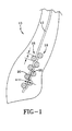
- FIG. 1 is a cross section view of a tire bead portion;
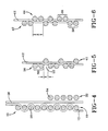
- FIG. 2 illustrates the lay up order and spacing of the wires in the bead portion; and
- FIGS. 3-6 are alternative bead wire and carcass ply configurations.
-
- FIG. 1 illustrates a
bead portion 10 of a cured tire in accordance with the present invention. Thecarcass ply 12 is formed bycords 14 that are oriented radially in the sidewalls. Thecarcass cords 14 are wound continuously between a first radially inward end and at least a radially outer location. One method of cord placement and how the cords may be placed in the tire is disclosed in EP-A- 1 447 209 and in unpublished EP application No. 04102216. - The tire is formed with the conventional tire elements of opposing sidewalls, a tread extending between the sidewalls, a belt package located below the tread, and a pair of opposing
bead portions 10 located radially inward of the sidewalls. Other than the bead portion configuration disclosed herein, the above tire elements may be of any conventional design. - As shown in FIG. 1, at the radially inner end of the
carcass ply 12, in thebead portion 10 of the tire after the tire has been cured, thecarcass cords 14 are interwoven between twobead columns bead column bead wires 20. A "column" ofbead wires 20 is determined by all thewires 20 being on one side of thecarcass ply 12. Thebead wires 20 in eachcolumn wires 20 in theadjacent column carcass cords 14, thebead wires 20 in eachcolumn bead wires 20 in theadjacent column carcass cords 14 are interwoven about thebead wires 20 in such a manner as to create a zigzag path about the circumferentially offset and axially overlappingbead wires 20. The zigzag ply path of the ply ends changes direction at least four times as theply 12 is interwoven among thebead wires 20. - The
bead wires 20 are formed of any traditional and/or conventional bead wire materials. Thewires 20 may be monofilaments or have a bunched cords construction. The material used to form the monofilaments or bunched cords may be polyester, nylon, fiberglass, aramid, steel, carbon fiber, or any other high tensile material. Thewires 20 are skim coated to initially provide thewires 20 with sufficient tack to maintain placement of thewires 20 during building of the tire and to later provide thewires 20 with adhesion properties during curing of the tire. The thickness of the skim coating is nominal in comparison to the bead wire diameter dB. The diameter dB of thebead wires 20 is determined by the necessary strength of thebead region 10. The diameter dB of all the wires may be the identical or may different within onecolumn - The
carcass cords 14 are formed of any traditional or conventional wire materials. The wires may be monofilaments, bunched, or cabled cords. The material used to form thecords 14 may be polyester, nylon, fiberglass, aramid, steel, or carbon fiber. Thecords 14 are skim coated to initially provide with sufficient tack to maintain placement of thecords 14 during building of the tire and to later provide thecords 14 with adhesion properties during curing of the tire. The diameter dc of thecords 14 is determined by the necessary carcass strength of the bead region, and may be greater or less than the diameter dB of thebead wires 20. - By interweaving the
carcass cords 14 about the rows ofbead wires 20, thecarcass cords 14 are subjected to two types of mechanical interlocking. The first type of interlocking is mechanical in nature due to the geometry of the cord path relative to the bead wire columns. As the carcass plycords 14 are tensioned due to inflation, ply tension forces act to consolidate the bead configuration (much like a Chinese finger trap) resulting in increased retention of theply 12 with thebead wires 20. The second type of mechanical interlocking results from the inflation pressure of thetire 10 imparting a force on the bead structure against the wheel rim flange. This force against the inside bead face pushes the columns ofbead wires 20 together, further increasing the retention and interlocking of the carcass ply 12 with thebead wires 20. The addition of both types of mechanical interlocking result in a retention of theply cords 14 to bead material far greater than just the chemical bonding of the surrounding material. - The
bead region 10 of the tire may be assembled as illustrated in FIG. 2. Thebead wires 20 of the first circumferentially extendingbead column 16 are laid onto already laid elastomeric layers, the wires extending in the circumferential direction of the tire, parallel to the equatorial plane of the final tire. At a minimum, the elastomeric layers will include an inner liner layer. The individual wires are laid independent of each other, or, to reduce the amount of bead wire splicing or the number of different diameter wire hoops required to form the bead, thebead wire 20 in thesingle column bead wire 20 is laid spirally, thewires 20 are wire ends as seen in a cross-section of thetire bead portion 10. - A
gap 22 with a length z is created between circumferentiallyadjacent bead wires 20 to permit thebead wires 20 of thenext bead column 18 and thecarcass cords 14 to interlock with thefirst column 16. The gap has length z of at least twice the diameter dc of thecarcass cords 14 since thecarcass cords 14 are woven into and out of thegap 22. The gap length z is equivalent to the equation: - The
carcass cords 14 are then laid, extending radially. Thecords 14 are illustrated as inclined at 90° relative to an equatorial plane of the tire, but may be inclined at a lesser angle, down to 75° relative to the equatorial plane. Each individual cord may terminate radially below the bead wires, as illustrated, or may turn upwards to form anothercarcass cord 14. After thecarcass cords 14 are laid, thewires 20 of the next circumferentially extendingbead column 18 are laid. Eachsecond column wire 20 is laid in the gap z betweenadjacent wires 20 of thefirst column 16. The number of wire ends in thesecond column 18 in a cross-section of thetire bead portion 10 may or may not be identical to the number of wire ends in thefirst column 16; there may be more orless wires 20. - At the radially inner end, the
carcass cords 14 extend radially below thebead wires 20, creating atail 24 of length L. As the secondbead wire column 18 is formed by the application of thebead wires 20, thecarcass cords 14 are forced into thegap 22. As eachbead wire 20 is applied in thecolumn 18, the carcass cords gradually form the zigzag configuration seen in FIG. 1. The tail length L slowly decreases as thecords 14 are pushed into thegap 22. The final tail length L ideally is less than the bead wire diameter dB. - The amount of tension used during application of the second
bead wire column 18, in combination with thegap 22 distance z, will dictate the amount of axial overlap of thebead wires 20 in the adjacent bead columns. There are two different axial overlaps - as determined tangent to the beads in each bead column and as determined parallel to the equatorial plane of the tire. - The first axial overlap x is more easily determined prior to curing, but may be measured post-cure by the following steps: draw a first line through the centerlines of the
bead wires 20 in eachcolumn bead wire 20 where thebead wire 20 contacts thecarcass cords 14; and determine the overlap of the second lines for eachbead column - The second type of axial overlap, as determined parallel to the equatorial plane of the tire, may be referred to as bead wire overlap. This overlap is measured by the following steps: draw a first line tangent to a
single bead wire 20 in the axiallyinner bead column 16 where thebead wire 20 contacts thecarcass cord 14, the first line being parallel to the equatorial plane of the tire; draw a second line tangent to thebead wire 20 radially inward of thefirst bead wire 20 but in theother bead column 20, the second line being parallel to the equatorial plane of the tire; determine the overlap amount of the first and second lines, the overlap measurement should be transverse to the equatorial plane of the tire. - The column axial overlap x is preferably in the range of 5 to 100 percent of the bead wire diameter dB. The bead wire overlap is partially dictated by the inclination angle of the two bead columns, the inclination angle of the bead columns varying from 5° to 50° relative to the radial direction of the tire.
- In the tire bead portion of FIG. 3, a two ply tire bead portion is illustrated. A second carcass ply 26 is laid axially outward of the
second bead column 18. The second carcass ply also follows a zigzag configuration about thesecond bead column 18. The zigzag path of the second carcass ply 26 opposes the zigzag path of thefirst carcass ply 12, encompassing thebead wires 20 of thesecond column 18 between theplies plies wires 20 of thesecond bead column 18. - A third circumferentially extending
bead column 28 may be placed axially outward of the second carcass ply 26 to lock in thesecond carcass ply 26. Thewires 20 of thethird column 28 may be identical in formation to the other wires. When wound onto the green tire during formation, thewires 20 are placed in the gaps between thewires 20 of the secondbead wire column 18. When placed in this manner, the first and third columns are axially adjacent to thewires 20 of thefirst column 16, and radially offset from thewires 20 of thesecond column 18. - FIG. 4 shows an alternative bead region construction. The axial overlap x of the
wires 20 in the two overlappingbead wire columns second column 18. Thesecond ply 30 follows a smooth line, notwithstanding any manufacturing tolerances. Thesecond ply 30 contacts both thefirst ply 12 and thewires 20 of thesecond column 18. - Axially outward of the
second ply 30 may be athird column 32 ofbead wires 34. Thebead wires 34 of thecolumn 32 are radially and axially aligned. Thecolumn 32 may have a radial height less than the radial height of theother columns third column 32 may have a radial height similar to theother columns wires 34 of thethird column 32 may differ from thewires 20 of the first andsecond bead columns third column 32 of variable height or bead wire properties may also be used in the absence of thesecond ply 30. - In another aspect of the invention, as seen in FIG. 5 and 6, the number of directly radially
adjacent bead wires 20 in each bead column may vary. In the bead portion of FIG. 5, thefirst bead column 36 is defined by spacedpairs 38 ofbead wires 20. Thewires 20 of thesecond column 40 are singe wires placed in thegap 22. Thesecond column 40 may also comprise pairs of bead wires similar to thefirst column 36, in which case, thegap 22 will be great enough to accommodate the overlap wires of thesecond column 40. - In the bead portion of FIG. 6, the wires in each
column - For larger sized or heavy duty tires, such as aircraft tires, large truck tires such as drive or steer tires, off-the-road tires, agricultural tires, mining tiers, etc, the exact bead portion construction, including the number of carcass plies and how they are applied as well as the number of bead columns and the number of bead wires in a column, may vary. It is within the scope of this invention to vary the number and placement of carcass plies so long as there is a single carcass ply that is interwoven between a plurality of bead wires. For example, meant by way of illustration only, a pair of adjacent carcass cords may be collectively woven as a single cord in a zigzag path about the wires of two bead wire columns. It is also within the scope of the invention to increase the number of bead wire columns, vary the number of wires in a column, or vary the diameter of the wires.
Claims (10)
- A pneumatic tire comprising a reinforcing carcass ply (12) and opposing bead portions (10), the carcass ply (21) comprising one or more cords (14) wound continuously between a first end and a second end, characterized in that the carcass ply cords (14) are interwoven among a plurality of bead wires (20).
- The tire of claim 1, wherein the first end of the carcass ply (12) is located in one of the opposing bead portions (10), and wherein in the one of the opposing bead portions (10), the carcass ply cords (14) are interwoven among a plurality of circumferentially oriented bead wires (20).
- The tire of claim 1 or 2, wherein the carcass ply (12) comprising one or more cords (14) wound continuously between the opposing bead portions (10) forming ends of the ply (12) in each bead portion (10), and wherein the ply ends are interwoven in a zigzag path among a plurality of bead wires (20).
- The tire of at least one of the previous claims, wherein the carcass ply cords (14) are interwoven such that the first end of the carcass ply (12) follows a zigzag path.
- The tire of at least one of the previous claims, wherein the bead wires (20) form at least two radially extending columns (16, 18) of bead wires (20).
- The tire of claim 5, wherein the bead wires (20) in one radially extending column (16, 18) are radially offset from the bead wires (20) in the adjacent radially extending column (16, 18), or wherein the bead wires (20) in one radially extending column (16, 18) axially overlap the bead wires (20) in the adjacent column (16, 18).
- The tire of claim 6, wherein the overlap distance (x) of the bead wires (20) is 5 to 100% of the bead wire diameter (dB), or wherein the bead wires (20) in each column (16, 18) are spaced by a distance (z) equivalent to z ≥ 2dC + 0.5dB wherein dc is the diameter of the carcass ply cords (14) and dB is the diameter of the bead wires (20).
- The tire of at least one of the previous claims, wherein the tire further comprises a second carcass ply (30), the second carcass ply (30) having a first end and a second end, the first end being located in the one of the opposing bead portions (10) and being interwoven among the plurality of circumferentially oriented bead wires (20, 34).
- The tire of claim 8, wherein in the region of the radially inward first ends of the first and second carcass ply (12, 20), the carcass plies (12, 20) follow opposing zig-zag paths, encompassing bead wires (20, 34) between the carcass plies (12, 20).
- The tire of at least one of the previous claims, wherein the plurality of circumferentially oriented bead wires (20, 34) form at least three radially extending columns of bead wires.
Applications Claiming Priority (2)
| Application Number | Priority Date | Filing Date | Title |
|---|---|---|---|
| US667536 | 2003-09-22 | ||
| US10/667,536 US6966351B2 (en) | 2003-09-22 | 2003-09-22 | Tire bead configuration |
Publications (2)
| Publication Number | Publication Date |
|---|---|
| EP1516752A1 true EP1516752A1 (en) | 2005-03-23 |
| EP1516752B1 EP1516752B1 (en) | 2008-06-25 |
Family
ID=34194791
Family Applications (1)
| Application Number | Title | Priority Date | Filing Date |
|---|---|---|---|
| EP04104545A Expired - Fee Related EP1516752B1 (en) | 2003-09-22 | 2004-09-20 | Tire bead configuration |
Country Status (5)
| Country | Link |
|---|---|
| US (1) | US6966351B2 (en) |
| EP (1) | EP1516752B1 (en) |
| JP (1) | JP4723837B2 (en) |
| BR (1) | BRPI0403969A (en) |
| DE (1) | DE602004014568D1 (en) |
Cited By (1)
| Publication number | Priority date | Publication date | Assignee | Title |
|---|---|---|---|---|
| EP3546253A1 (en) * | 2013-03-15 | 2019-10-02 | Bridgestone Americas Tire Operations, LLC | Pneumatic tire and method of manufacture |
Families Citing this family (10)
| Publication number | Priority date | Publication date | Assignee | Title |
|---|---|---|---|---|
| JP4520217B2 (en) * | 2004-05-21 | 2010-08-04 | 東洋ゴム工業株式会社 | Pneumatic radial tire |
| JP2006347363A (en) * | 2005-06-16 | 2006-12-28 | Bridgestone Corp | Pneumatic tire, its manufacturing device and manufacturing method |
| US7484545B2 (en) * | 2005-12-20 | 2009-02-03 | The Goodyear Tire & Rubber Co. | Radial tire for aircraft with specified merged cords |
| US20110146873A1 (en) | 2009-12-22 | 2011-06-23 | Marc Weydert | Pneumatic tire with rubber component containing epoxidized palm oil |
| US20120067485A1 (en) * | 2010-09-20 | 2012-03-22 | Serge Julien Auguste Imhoff | Pneumatic tire and method for making a pneumatic tire |
| US8622106B1 (en) | 2012-08-27 | 2014-01-07 | The Goodyear Tire & Rubber Company | Bead structure for a pneumatic tire |
| US9433971B2 (en) | 2012-10-04 | 2016-09-06 | The Goodyear Tire & Rubber Company | Atmospheric plasma treatment of reinforcement cords and use in rubber articles |
| US9441325B2 (en) | 2012-10-04 | 2016-09-13 | The Goodyear Tire & Rubber Company | Atmospheric plasma treatment of reinforcement cords and use in rubber articles |
| FR3030467B1 (en) * | 2014-12-23 | 2017-01-06 | Michelin & Cie | DEVICE FOR REMOVING AN ONDULATED WIRE ON A RECEPTION SURFACE |
| JP6696538B2 (en) * | 2018-08-21 | 2020-05-20 | 横浜ゴム株式会社 | Tire manufacturing method, molding system, and tire |
Citations (5)
| Publication number | Priority date | Publication date | Assignee | Title |
|---|---|---|---|---|
| GB320535A (en) * | 1928-10-25 | 1929-10-17 | India Rubber Gutta Percha Tele | Improvements in or relating to pneumatic tyre casings |
| GB393312A (en) * | 1931-12-02 | 1933-06-02 | India Rubber Gutta Percha Tele | Improvements in or relating to pneumatic tyre-casings |
| WO2002030690A1 (en) * | 2000-10-10 | 2002-04-18 | Societe De Technologie Michelin | Tire bead with soft heel |
| US20020124935A1 (en) * | 1998-10-30 | 2002-09-12 | Renato Caretta | Carcass structure for vehicle-wheel tyres and its method of manufacturing |
| JP2004098826A (en) * | 2002-09-09 | 2004-04-02 | Bridgestone Corp | Pneumatic radial tire and its manufacturing method |
Family Cites Families (22)
| Publication number | Priority date | Publication date | Assignee | Title |
|---|---|---|---|---|
| NL95227C (en) * | 1957-03-14 | Michelin & Cie | ||
| NL262212A (en) * | 1960-03-10 | 1900-01-01 | ||
| FR1327810A (en) * | 1962-04-09 | 1963-05-24 | Fr Du Pneu Englebert Soc | Advanced tire heel |
| NL129169C (en) * | 1963-05-04 | Michelin & Cie | ||
| FR2278509A1 (en) * | 1974-03-29 | 1976-02-13 | Kleber Colombes | TIRES FOR VEHICLES |
| MX153272A (en) * | 1978-09-08 | 1986-09-08 | Lim Kunststoff Tech Gmbh | PROCEDURE AND APPARATUS FOR THE MANUFACTURE OF AN IMPROVED PNEUMATIC TIRE |
| GB8519579D0 (en) * | 1985-08-03 | 1985-09-11 | Apsley Metals Ltd | Pneumatic tyres |
| US4811772A (en) * | 1985-11-05 | 1989-03-14 | Jonny Janus | Pneumatic tire having multi-part annular bead core |
| US5660656A (en) * | 1992-08-05 | 1997-08-26 | Sedepro | Tire with anchored carcass |
| FR2715348A1 (en) * | 1994-01-21 | 1995-07-28 | Sedepro | Anchoring the carcass of a tire. |
| FR2736006A1 (en) * | 1995-06-29 | 1997-01-03 | Sedepro | TIRE COMPRISING CIRCUMFERENTIAL CABLES FOR ANCHORING THE CARCASS, PROCESS FOR PREPARING SUCH CABLES |
| US5885387A (en) * | 1995-12-08 | 1999-03-23 | Sumitomo Rubber Industries, Ltd. | Pneumatic tire having endless carcass cord ply |
| FR2771050B1 (en) * | 1997-11-14 | 1999-12-24 | Michelin & Cie | PNEUMATIC TIRE-FREE BUCKLE |
| GB9724053D0 (en) * | 1997-11-15 | 1998-01-14 | Sumitomo Rubber Ind | Improved pneumatic tyre constructuon and manufacturing method |
| US6457504B1 (en) | 1998-07-31 | 2002-10-01 | Pirelli Pneumatici S.P.A. | Carcass structure for vehicle tires |
| JP4201900B2 (en) * | 1998-12-21 | 2008-12-24 | 株式会社ブリヂストン | Heavy duty pneumatic tire and manufacturing method thereof |
| JP2001097010A (en) * | 1999-09-30 | 2001-04-10 | Bridgestone Corp | Pneumatic tire |
| JP4363507B2 (en) * | 2000-08-31 | 2009-11-11 | 横浜ゴム株式会社 | Pneumatic radial tire |
| KR20020092667A (en) * | 2001-06-05 | 2002-12-12 | 한국타이어 주식회사 | Pneumatic tire for vehicle |
| JP4323131B2 (en) * | 2002-03-04 | 2009-09-02 | 株式会社ブリヂストン | Pneumatic tire |
| JP4520217B2 (en) * | 2004-05-21 | 2010-08-04 | 東洋ゴム工業株式会社 | Pneumatic radial tire |
| JP4458942B2 (en) * | 2004-06-09 | 2010-04-28 | 東洋ゴム工業株式会社 | Pneumatic radial tire |
-
2003
- 2003-09-22 US US10/667,536 patent/US6966351B2/en not_active Expired - Fee Related
-
2004
- 2004-09-15 BR BR0403969-6A patent/BRPI0403969A/en not_active IP Right Cessation
- 2004-09-20 DE DE602004014568T patent/DE602004014568D1/en active Active
- 2004-09-20 EP EP04104545A patent/EP1516752B1/en not_active Expired - Fee Related
- 2004-09-21 JP JP2004273566A patent/JP4723837B2/en not_active Expired - Fee Related
Patent Citations (5)
| Publication number | Priority date | Publication date | Assignee | Title |
|---|---|---|---|---|
| GB320535A (en) * | 1928-10-25 | 1929-10-17 | India Rubber Gutta Percha Tele | Improvements in or relating to pneumatic tyre casings |
| GB393312A (en) * | 1931-12-02 | 1933-06-02 | India Rubber Gutta Percha Tele | Improvements in or relating to pneumatic tyre-casings |
| US20020124935A1 (en) * | 1998-10-30 | 2002-09-12 | Renato Caretta | Carcass structure for vehicle-wheel tyres and its method of manufacturing |
| WO2002030690A1 (en) * | 2000-10-10 | 2002-04-18 | Societe De Technologie Michelin | Tire bead with soft heel |
| JP2004098826A (en) * | 2002-09-09 | 2004-04-02 | Bridgestone Corp | Pneumatic radial tire and its manufacturing method |
Non-Patent Citations (1)
| Title |
|---|
| PATENT ABSTRACTS OF JAPAN vol. 2003, no. 12 5 December 2003 (2003-12-05) * |
Cited By (1)
| Publication number | Priority date | Publication date | Assignee | Title |
|---|---|---|---|---|
| EP3546253A1 (en) * | 2013-03-15 | 2019-10-02 | Bridgestone Americas Tire Operations, LLC | Pneumatic tire and method of manufacture |
Also Published As
| Publication number | Publication date |
|---|---|
| BRPI0403969A (en) | 2005-05-24 |
| US20050061414A1 (en) | 2005-03-24 |
| EP1516752B1 (en) | 2008-06-25 |
| JP2005096755A (en) | 2005-04-14 |
| DE602004014568D1 (en) | 2008-08-07 |
| JP4723837B2 (en) | 2011-07-13 |
| US6966351B2 (en) | 2005-11-22 |
Similar Documents
| Publication | Publication Date | Title |
|---|---|---|
| US11325418B2 (en) | Tire assembly comprising a breakable structure and a supporting structure | |
| EP3459763B1 (en) | Tire | |
| US5709760A (en) | Thin gauge, fine diameter steel cord reinforced tire ply fabric which is lap spliced | |
| US20080105352A1 (en) | Reduced weight aircraft tire | |
| KR101970365B1 (en) | Accordion spiral overlay for a pneumatic tire | |
| EP2058146B1 (en) | Pneumatic tire | |
| EP3838623B1 (en) | Truck tire | |
| EP1516752B1 (en) | Tire bead configuration | |
| EP2977229B1 (en) | Reduced weight aircraft tire | |
| US20170057291A1 (en) | Reduced weight aircraft tire | |
| US6709540B1 (en) | Composite ply structure for tires and method of manufacture | |
| EP3895910B1 (en) | Tire with cut protector belt structure | |
| JP2783826B2 (en) | Pneumatic tire | |
| JPH0939512A (en) | Pneumatic tire | |
| EP3173222A1 (en) | A method of manufacturing a tire with a monolayer belt component and pneumatic tire | |
| EP2199108B1 (en) | Pneumatic tire | |
| EP1112869B1 (en) | Continuous folded belt and splice therefore | |
| EP4144539A1 (en) | Pneumatic tire for use on truck | |
| EP3290232B1 (en) | Tire with low weight and high burst strength | |
| US20050076989A1 (en) | Tyres for vehicle wheels with improved bead structure | |
| EP1211103B1 (en) | Tire with segmented belt | |
| EP3081395A1 (en) | A continuous crown reinforcement for a pneumatic tire | |
| EP1192052B1 (en) | Composite ply structure for tires and method of manufacture | |
| EP2202094A1 (en) | Offset zigzag belt structure for a pneumatic tire | |
| CA2145789C (en) | Pneumatic tire and an unvulcanized carcass as an intermediate article in its manufacture |
Legal Events
| Date | Code | Title | Description |
|---|---|---|---|
| PUAI | Public reference made under article 153(3) epc to a published international application that has entered the european phase |
Free format text: ORIGINAL CODE: 0009012 |
|
| AK | Designated contracting states |
Kind code of ref document: A1 Designated state(s): AT BE BG CH CY CZ DE DK EE ES FI FR GB GR HU IE IT LI LU MC NL PL PT RO SE SI SK TR |
|
| AX | Request for extension of the european patent |
Extension state: AL HR LT LV MK |
|
| 17P | Request for examination filed |
Effective date: 20050923 |
|
| AKX | Designation fees paid |
Designated state(s): DE FR GB IT |
|
| 17Q | First examination report despatched |
Effective date: 20070529 |
|
| GRAP | Despatch of communication of intention to grant a patent |
Free format text: ORIGINAL CODE: EPIDOSNIGR1 |
|
| GRAS | Grant fee paid |
Free format text: ORIGINAL CODE: EPIDOSNIGR3 |
|
| GRAA | (expected) grant |
Free format text: ORIGINAL CODE: 0009210 |
|
| AK | Designated contracting states |
Kind code of ref document: B1 Designated state(s): DE FR GB IT |
|
| REG | Reference to a national code |
Ref country code: GB Ref legal event code: FG4D |
|
| REF | Corresponds to: |
Ref document number: 602004014568 Country of ref document: DE Date of ref document: 20080807 Kind code of ref document: P |
|
| PGFP | Annual fee paid to national office [announced via postgrant information from national office to epo] |
Ref country code: GB Payment date: 20080708 Year of fee payment: 5 |
|
| PLBE | No opposition filed within time limit |
Free format text: ORIGINAL CODE: 0009261 |
|
| STAA | Information on the status of an ep patent application or granted ep patent |
Free format text: STATUS: NO OPPOSITION FILED WITHIN TIME LIMIT |
|
| 26N | No opposition filed |
Effective date: 20090326 |
|
| GBPC | Gb: european patent ceased through non-payment of renewal fee |
Effective date: 20090920 |
|
| PG25 | Lapsed in a contracting state [announced via postgrant information from national office to epo] |
Ref country code: GB Free format text: LAPSE BECAUSE OF NON-PAYMENT OF DUE FEES Effective date: 20090920 |
|
| PGFP | Annual fee paid to national office [announced via postgrant information from national office to epo] |
Ref country code: FR Payment date: 20100920 Year of fee payment: 7 Ref country code: IT Payment date: 20100918 Year of fee payment: 7 |
|
| PGFP | Annual fee paid to national office [announced via postgrant information from national office to epo] |
Ref country code: DE Payment date: 20100930 Year of fee payment: 7 |
|
| PG25 | Lapsed in a contracting state [announced via postgrant information from national office to epo] |
Ref country code: IT Free format text: LAPSE BECAUSE OF NON-PAYMENT OF DUE FEES Effective date: 20110920 |
|
| REG | Reference to a national code |
Ref country code: FR Ref legal event code: ST Effective date: 20120531 |
|
| REG | Reference to a national code |
Ref country code: DE Ref legal event code: R119 Ref document number: 602004014568 Country of ref document: DE Effective date: 20120403 |
|
| PG25 | Lapsed in a contracting state [announced via postgrant information from national office to epo] |
Ref country code: DE Free format text: LAPSE BECAUSE OF NON-PAYMENT OF DUE FEES Effective date: 20120403 |
|
| PG25 | Lapsed in a contracting state [announced via postgrant information from national office to epo] |
Ref country code: FR Free format text: LAPSE BECAUSE OF NON-PAYMENT OF DUE FEES Effective date: 20110930 |