EP1792685A2 - Method and apparatus for identifying three dimensional coordinates on a tire - Google Patents
Method and apparatus for identifying three dimensional coordinates on a tire Download PDFInfo
- Publication number
- EP1792685A2 EP1792685A2 EP06125195A EP06125195A EP1792685A2 EP 1792685 A2 EP1792685 A2 EP 1792685A2 EP 06125195 A EP06125195 A EP 06125195A EP 06125195 A EP06125195 A EP 06125195A EP 1792685 A2 EP1792685 A2 EP 1792685A2
- Authority
- EP
- European Patent Office
- Prior art keywords
- tire
- target region
- bead
- distance
- coordinates
- Prior art date
- Legal status (The legal status is an assumption and is not a legal conclusion. Google has not performed a legal analysis and makes no representation as to the accuracy of the status listed.)
- Withdrawn
Links
Images


Classifications
-
- B—PERFORMING OPERATIONS; TRANSPORTING
- B60—VEHICLES IN GENERAL
- B60C—VEHICLE TYRES; TYRE INFLATION; TYRE CHANGING; CONNECTING VALVES TO INFLATABLE ELASTIC BODIES IN GENERAL; DEVICES OR ARRANGEMENTS RELATED TO TYRES
- B60C13/00—Tyre sidewalls; Protecting, decorating, marking, or the like, thereof
- B60C13/001—Decorating, marking or the like
-
- B—PERFORMING OPERATIONS; TRANSPORTING
- B29—WORKING OF PLASTICS; WORKING OF SUBSTANCES IN A PLASTIC STATE IN GENERAL
- B29D—PRODUCING PARTICULAR ARTICLES FROM PLASTICS OR FROM SUBSTANCES IN A PLASTIC STATE
- B29D30/00—Producing pneumatic or solid tyres or parts thereof
- B29D30/0061—Accessories, details or auxiliary operations not otherwise provided for
-
- B—PERFORMING OPERATIONS; TRANSPORTING
- B44—DECORATIVE ARTS
- B44B—MACHINES, APPARATUS OR TOOLS FOR ARTISTIC WORK, e.g. FOR SCULPTURING, GUILLOCHING, CARVING, BRANDING, INLAYING
- B44B7/00—Machines, apparatus or hand tools for branding, e.g. using radiant energy such as laser beams
- B44B7/007—Machines, apparatus or hand tools for branding, e.g. using radiant energy such as laser beams using a computer control means
-
- B—PERFORMING OPERATIONS; TRANSPORTING
- B44—DECORATIVE ARTS
- B44C—PRODUCING DECORATIVE EFFECTS; MOSAICS; TARSIA WORK; PAPERHANGING
- B44C1/00—Processes, not specifically provided for elsewhere, for producing decorative surface effects
- B44C1/22—Removing surface-material, e.g. by engraving, by etching
- B44C1/228—Removing surface-material, e.g. by engraving, by etching by laser radiation
-
- B—PERFORMING OPERATIONS; TRANSPORTING
- B29—WORKING OF PLASTICS; WORKING OF SUBSTANCES IN A PLASTIC STATE IN GENERAL
- B29D—PRODUCING PARTICULAR ARTICLES FROM PLASTICS OR FROM SUBSTANCES IN A PLASTIC STATE
- B29D30/00—Producing pneumatic or solid tyres or parts thereof
- B29D30/06—Pneumatic tyres or parts thereof (e.g. produced by casting, moulding, compression moulding, injection moulding, centrifugal casting)
- B29D30/72—Side-walls
- B29D2030/728—Decorating or marking the sidewalls after tyre vulcanization
-
- B—PERFORMING OPERATIONS; TRANSPORTING
- B29—WORKING OF PLASTICS; WORKING OF SUBSTANCES IN A PLASTIC STATE IN GENERAL
- B29L—INDEXING SCHEME ASSOCIATED WITH SUBCLASS B29C, RELATING TO PARTICULAR ARTICLES
- B29L2030/00—Pneumatic or solid tyres or parts thereof
- B29L2030/007—Sidewalls
Definitions
- the invention relates generally to methods and apparatus for identifying a three dimensional region on a toroidal body and, more particularly, three dimensional coordinates on a tire for subsequent laser engraving.
- the desired solution to the industry's need must avoid the use of edge-detection throughout an entire image and have a cycle time as short as practical.
- the methodology should expeditiously identify a specific region of interest through use of mathematical tools and avoid unnecessary edge detection steps.
- the Z-coordinate of the target area is determined, preferably by use of a laser distance measuring device, whereby establishing 3D coordinates for the target region.
- the target region slope may be calculated from Z-coordinate measurements.
- a preferred line of attack for an information inscribing device may thus be identified, the preferred line of attack being substantially normal to the calculated slope of the target region.
- the invention also relates to a method according to claim 4.
- Yet another aspect of the invention is to provide an apparatus according to claim 8 for performing the claimed methods.
- the information inscribing device comprises an engraving laser.
- a robotic apparatus 10 is shown suitable for use in the practice of the subject invention and consistent with robotic technology commonly available to the industry.
- the apparatus 10 employs a multi-arm linkage formed by a generally horizontal arm 12 pivotally connecting to a generally vertical support arm 14.
- Support arm 14 is connected to a freestanding support base 16.
- a clamping mechanism 18 At the remote free end of the arm 12 is a clamping mechanism 18. While shown in a functional configuration suitable for the invention, other robotic apparatus configurations may be employed if so desired.
- a drive assembly 20 is connected to the arm linkages 12, 14 and a flexible wiring conduit 22 extends control and power lines from the base 16 to the remote end of arm 12.
- the apparatus 10 incorporates multiple pivot axes for adjustment purposes.
- the arm 12 pivotally attaches to arm 14 by pin assembly 24 and the clamping end of arm 12 is pivotally coupled to the clamp mechanism 18 by pivot pin assembly 23.
- the arm 14 may be pivotally coupled to the base to allow repositionment of the clamp end 18 about multiple adjustment axes.
- a laser distance-measuring device and engraving laser are attached to the clamp end 18.
- Laser 26 is of a type commercially available, such as the Model Polaris 250 laser sold by Lap Laser LLC located in Cincinnati, Ohio.
- Laser 27 is likewise of a type commercially available such as, the Model Smartlase 110, sold by Markem Co., of Keene, N.H.
- a digital camera 28 is employed, the camera having an optical axis centered within view range 30.
- a workstation is shown in FIGS. 7-11 to include the robotic apparatus 10 and a conveyor belt 32. Conveyor belt is driven by a drive motor 34 and conveys a series of tires 38 on a belt surface 36 below the robotic apparatus end 18.
- Tires 38 are structured conventionally to include a crown 40, a sidewall 42, a bead region 44, and a lower sidewall 46.
- a target region 48 is identified during manufacture of the tire 38.
- the region of interest is created preferably by using a metal blank serial tag in the tire mold instead of a serial tag containing the normal code marking. So manufactured, sufficient lighting directed on the cured tire will create a bright area on the image where the target region is located.
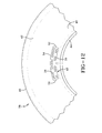
- FIG. 12 illustrates a target region 48 on a lower sidewall of a tire 38.
- the region is generally a quadrilateral shape having rounded corners.
- the region is bounded by opposite ends 50, 52 and longitudinal sides 54, 56.
- Placed within the region 48 by suitably permanent means is information 58 required to comply with the requirements of the act and any other information deemed important to the manufacturer. For example, information identifying the equipment used to manufacture the tire may be encoded into the target region 48.
- the laser 26 emits a directional beam of light 60.
- a target tire 38 is advanced by the conveyor system to a location beneath the digital camera 28.
- the centerline 62 of the tire is coincident with the optical axis of the camera 28.
- Camera 28, located on the centerline 62 at a fixed position above the conveyor and camera optical axis is oriented perpendicularly to the conveyor belt 32.
- the conveyor is stopped so that the center of the target tire coincides with the center of the camera image.
- the camera is spaced a known distance from the tire such that the field of vision 30 of the camera 28 covers the majority of the tire 38 sidewall.
- a digital image is taken of the entire tire by the camera 28 and image data is transmitted from the camera to a data processor for analysis.
- a computer-vision algorithm uses image pixel brightness values to find the edge of the tire bead 44. It will be appreciated that the brightness of the bead region is differentiated from surrounding regions of black tire so as to allow the computer to differentiate pixel brightness values.
- FIG. 13 When a plurality, and specifically a minimum of three, image pixels on the tire bead edge are found, conventional geometric formulas such as illustrated in FIG. 13 may be used to calculate the bead circle's center and radius 64 (FIG. 9).
- the diagram and formulas of FIG. 13 are taken from ref: Pedoe, D. (1995) Circles: A Mathematical View.
- the bead circle's center and radius are then used to perform a pixel by pixel search (360-degree sweep following the bead circle region) around the bead circumference.
- the target region is located by differentiating the pixel brightness values of the target (date code) region from the surrounding black tire.
- the coordinates of the bead circle center and target region are sent from the data processor to the robotic controller (RC) of the robotic apparatus.
- the RC moves the LDM to a position above the target region as shown in FIG. 9.
- the LDM laser 26 measures the distance D1 from the LDM to a first point P1 within the target region and sends the distance data to the RC.
- the RC then moves the LDM to a second location above the target region along a line through the bead circle center.
- Distance D2 to a second point P2 within the target region is then determined by the LDM.
- the second point will lie on a line from the center of the bead circle through the first point P1.
- the LDM sends the new distance D2 to the second point P2 in the target region to the RC.
- the RC calculates the target region's slope with respect to horizontal from the difference between distances D1 and D2.
- the RC after calculating the slope of the target region, now has the set of full 3-D coordinates and orientation of the target region. Two dimensions are determined by the pixel brightness value scan and the third dimension determined by the LDM measurements. From the 3D coordinates, a preferred angle of attack (AOA) is calculated by the RC for the purposes of aiming an engraving laser at the target region.
- the RC sends control signals to the robot that aims the engraving laser 27 along an optimal laser line of attack 68 toward the target region.
- the line of attack 68 is perpendicular to the slope line of the region 48 as determined above.
- FIG. 5 illustrates the method of the invention in more detail.
- the conveyor moves the belt 70; the conveyor photoeyes send signals to the conveyor controller 72 and when a tire is moved to appropriate position, the conveyor controller stops the conveyor 74.
- a data processing computer calculates the target region X, Y coordinates from the pixel brightness sweep along the bead region 76 and sends coordinates to the robotic apparatus 78.
- the robotic apparatus moves the LDM to appropriate location 80 and sends a move complete signal to the computer 82.
- the LDM sends Z-coordinate for point P1 to the computer 84 and the computer then sends the second location P2 coordinates to the robot apparatus 86.
- the robotic apparatus moves the LDM to the second coordinate location 88 and the robot sends move complete signal to the computer 90.
- the LDM sends Z-coordinate to the computer for the second position P2 92.
- the computer calculates the 3D coordinates of the target region and a preferred angle of attack 94.
- the computer sends X,Y,Z and AOA coordinates to the robotic apparatus 96, the laser 27 is moved to appropriate position 98, and a move complete signal is returned to the computer 100.
- the computer sends a fire command to the laser 102 and the laser completes engraving and sends a ready signal to the computer 104.
- the computer sends home command to the robotic apparatus and a move command to the conveyor 106.
- the robotic apparatus moves to the home position 108 and the cycle may be repeated.
- the subject invention provides an effective method and apparatus for identifying 3-D coordinates of a target region on a tire for subsequent laser engraving.
- the method and apparatus function quickly, effectively, and efficiently in locating the 3-D coordinates of the tire region to be engraved.
Abstract
Description
- The invention relates generally to methods and apparatus for identifying a three dimensional region on a toroidal body and, more particularly, three dimensional coordinates on a tire for subsequent laser engraving.
- It is industry practice for certain information pertaining to tire, such as tire size, brand identification, inflation requirements, etc. to be integrally molded into the tire during its manufacture. With the passage of the US Transportation Recall Enhancement, Accountability, and Documentation (TREAD) Act, it is now a requirement that certain additional information be permanently incorporated into a tire which is not readily incorporated into the tire from the mold. For example, a new requirement is that the week/year of manufacture be integrally affixed to the tire in order to render certain its date of manufacture throughout the useful life of the tire. It is, however, impractical to comply with the new date code requirement by modifying the mold each week to mark the tires with the week/year of manufacture. To change a mold weekly to comply with the date code requirement of Tread Act would be unduly burdensome and would add significantly to the cost of tire manufacture.
- An alternative to incorporating such information into a tire is to engrave the information into the tire by laser in a post-cure operation. In addition to information necessary for compliance with the Tread Act, it could be beneficial to integrate other information such as plant and press identification for future reference.
- In order for laser engraving to be employed in permanently incorporating reference information into a tire, the means for quickly, effectively, and efficiently locating three dimensional coordinates of the tire region to be engraved is necessary. Prior techniques have centered on the use of line scan cameras that require both the tire to be chucked on a spindle and a camera mounted at a comparatively close distance. The line scan camera uses traditional edge-detection techniques to locate by edge-detection the entire image or region to be engraved. Such a technique requires an additional programmatic method to find the specific region of interest, undesirably adding a time consuming step in the tire manufacturing process.
- A need accordingly exists for quickly, effectively, and efficiently locating three dimensional coordinates of the tire region to be engraved. The desired solution to the industry's need must avoid the use of edge-detection throughout an entire image and have a cycle time as short as practical. The methodology should expeditiously identify a specific region of interest through use of mathematical tools and avoid unnecessary edge detection steps.
- Pursuant to one aspect of the invention, a method for identifying coordinates of a target region according to claim 1 is disclosed.
- According to another aspect of the invention, the Z-coordinate of the target area is determined, preferably by use of a laser distance measuring device, whereby establishing 3D coordinates for the target region.
- In another aspect of the invention, the target region slope may be calculated from Z-coordinate measurements. A preferred line of attack for an information inscribing device may thus be identified, the preferred line of attack being substantially normal to the calculated slope of the target region.
- The invention also relates to a method according to claim 4.
- Yet another aspect of the invention is to provide an apparatus according to claim 8 for performing the claimed methods. Preferably, the information inscribing device comprises an engraving laser.
- Dependent claims cover preferred embodiments of the invention.
- The invention will be described by way of example and with reference to the accompanying drawings in which:
- FIG. 1 is a top plan view of a robotic apparatus for directing a laser distance-measuring device pursuant to the invention.
- FIG. 2 is a side elevation view thereof.
- FIG. 3 is a front elevation view thereof.
- FIG. 4 is a side elevation view thereof showing in phantom alternative orientations of the robotic apparatus.
- FIG. 5 is a block diagram for the method of identifying 3-D coordinates of a target tire region pursuant to the invention.
- FIG. 6 is a side elevation view of the robotic apparatus, camera apparatus, and a tire conveyor station.
- FIG. 7 is a side elevation view of a workstation comprising the conveyor station, the robotic apparatus, and the camera apparatus.
- FIG. 8 is top plan view of the workstation with the camera assembly in position to capture an image of the tire.
- FIG. 9 is an end elevation view of the workstation showing the laser distance-measuring device measuring dual target region points.
- FIG. 10 is a top plan view of the workstation showing the laser measuring device in an operative orientation to the tire.
- FIG. 11 is an end elevation view of the workstation showing the laser engraving device in an operative orientation to the tire.
- FIG. 12 is a plan view of a tire portion showing location of the target region and engraved information.
- FIG. 13 is a bead circle center and radius formula utilized in identifying three-dimensional coordinates on a tire.
- Referring to FIGS. 1-4, a
robotic apparatus 10 is shown suitable for use in the practice of the subject invention and consistent with robotic technology commonly available to the industry. Theapparatus 10 employs a multi-arm linkage formed by a generallyhorizontal arm 12 pivotally connecting to a generallyvertical support arm 14.Support arm 14 is connected to afreestanding support base 16. At the remote free end of thearm 12 is aclamping mechanism 18. While shown in a functional configuration suitable for the invention, other robotic apparatus configurations may be employed if so desired. Adrive assembly 20 is connected to thearm linkages flexible wiring conduit 22 extends control and power lines from thebase 16 to the remote end ofarm 12. As shown by FIGS. 1-4, theapparatus 10 incorporates multiple pivot axes for adjustment purposes. Thearm 12 pivotally attaches toarm 14 bypin assembly 24 and the clamping end ofarm 12 is pivotally coupled to theclamp mechanism 18 bypivot pin assembly 23. In addition, thearm 14 may be pivotally coupled to the base to allow repositionment of theclamp end 18 about multiple adjustment axes. - With reference to FIGS. 7, 8, 9, 10, and 11, a laser distance-measuring device (LDM) and engraving laser are attached to the
clamp end 18. Laser 26 is of a type commercially available, such as the Model Polaris 250 laser sold by Lap Laser LLC located in Cincinnati, Ohio. Laser 27 is likewise of a type commercially available such as, the Model Smartlase 110, sold by Markem Co., of Keene, N.H. In addition adigital camera 28 is employed, the camera having an optical axis centered withinview range 30. A workstation is shown in FIGS. 7-11 to include therobotic apparatus 10 and aconveyor belt 32. Conveyor belt is driven by adrive motor 34 and conveys a series oftires 38 on abelt surface 36 below therobotic apparatus end 18.Tires 38 are structured conventionally to include acrown 40, asidewall 42, abead region 44, and alower sidewall 46. As best seen from FIG. 12, atarget region 48 is identified during manufacture of the tire 38.The region of interest is created preferably by using a metal blank serial tag in the tire mold instead of a serial tag containing the normal code marking. So manufactured, sufficient lighting directed on the cured tire will create a bright area on the image where the target region is located. - In general, it is conventional to employ a series of discrete regions spaced circumferentially on the
lower sidewall 46 proximate to thebead region 44. The discrete regions are used for informational purposes. Molded into such regions is information relating to the tire, such as tire size, inflation specifications, manufacturing data, etc. In the enacted TREAD Act, there is a further requirement that every tire carry a date code within a specific additional region at a specific location on the tire. The designated region is the last appearing region in a clockwise direction following the series of regions carrying conventional information. The statutory requirement is for the placement of week/year of manufacture information in permanent fashion within the last appearing region, whether by molding the information in or by a post tire manufacturing operation such as engraving. - The challenges attendant molding in such date coded information was explained previously. Using an engraving procedure carries certain difficulties given that the target region is located on a sidewall radius. In order to automate the engraving procedure, therefore, it is important to devise a method for accurately identifying and locating the target region in three dimensions (3D).
- FIG. 12 illustrates a
target region 48 on a lower sidewall of atire 38. The region is generally a quadrilateral shape having rounded corners. The region is bounded by opposite ends 50, 52 andlongitudinal sides region 48 by suitably permanent means isinformation 58 required to comply with the requirements of the act and any other information deemed important to the manufacturer. For example, information identifying the equipment used to manufacture the tire may be encoded into thetarget region 48. - With continued reference to FIGS. 6-11, the
laser 26 emits a directional beam oflight 60. As shown in FIG. 6, atarget tire 38 is advanced by the conveyor system to a location beneath thedigital camera 28. Thecenterline 62 of the tire is coincident with the optical axis of thecamera 28.Camera 28, located on thecenterline 62 at a fixed position above the conveyor and camera optical axis is oriented perpendicularly to theconveyor belt 32. The conveyor is stopped so that the center of the target tire coincides with the center of the camera image. The camera is spaced a known distance from the tire such that the field ofvision 30 of thecamera 28 covers the majority of thetire 38 sidewall. A digital image is taken of the entire tire by thecamera 28 and image data is transmitted from the camera to a data processor for analysis. A computer-vision algorithm uses image pixel brightness values to find the edge of thetire bead 44. It will be appreciated that the brightness of the bead region is differentiated from surrounding regions of black tire so as to allow the computer to differentiate pixel brightness values. - When a plurality, and specifically a minimum of three, image pixels on the tire bead edge are found, conventional geometric formulas such as illustrated in FIG. 13 may be used to calculate the bead circle's center and radius 64 (FIG. 9). The diagram and formulas of FIG. 13 are taken from ref: Pedoe, D. (1995) Circles: A Mathematical View. The bead circle's center and radius are then used to perform a pixel by pixel search (360-degree sweep following the bead circle region) around the bead circumference. The target region is located by differentiating the pixel brightness values of the target (date code) region from the surrounding black tire. The coordinates of the bead circle center and target region are sent from the data processor to the robotic controller (RC) of the robotic apparatus. The RC moves the LDM to a position above the target region as shown in FIG. 9.
- The
LDM laser 26 measures the distance D1 from the LDM to a first point P1 within the target region and sends the distance data to the RC. The RC then moves the LDM to a second location above the target region along a line through the bead circle center. Distance D2 to a second point P2 within the target region is then determined by the LDM. The second point will lie on a line from the center of the bead circle through the first point P1. The LDM sends the new distance D2 to the second point P2 in the target region to the RC. The RC calculates the target region's slope with respect to horizontal from the difference between distances D1 and D2. - The RC, after calculating the slope of the target region, now has the set of full 3-D coordinates and orientation of the target region. Two dimensions are determined by the pixel brightness value scan and the third dimension determined by the LDM measurements. From the 3D coordinates, a preferred angle of attack (AOA) is calculated by the RC for the purposes of aiming an engraving laser at the target region. The RC sends control signals to the robot that aims the
engraving laser 27 along an optimal laser line ofattack 68 toward the target region. The line ofattack 68 is perpendicular to the slope line of theregion 48 as determined above. - The block diagram of FIG. 5 illustrates the method of the invention in more detail. As shown therein, the conveyor moves the
belt 70; the conveyor photoeyes send signals to theconveyor controller 72 and when a tire is moved to appropriate position, the conveyor controller stops theconveyor 74. A data processing computer calculates the target region X, Y coordinates from the pixel brightness sweep along thebead region 76 and sends coordinates to therobotic apparatus 78. The robotic apparatus moves the LDM toappropriate location 80 and sends a move complete signal to thecomputer 82. The LDM sends Z-coordinate for point P1 to thecomputer 84 and the computer then sends the second location P2 coordinates to therobot apparatus 86. The robotic apparatus moves the LDM to the second coordinatelocation 88 and the robot sends move complete signal to thecomputer 90. The LDM sends Z-coordinate to the computer for thesecond position P2 92. The computer calculates the 3D coordinates of the target region and a preferred angle ofattack 94. The computer sends X,Y,Z and AOA coordinates to therobotic apparatus 96, thelaser 27 is moved toappropriate position 98, and a move complete signal is returned to thecomputer 100. The computer sends a fire command to thelaser 102 and the laser completes engraving and sends a ready signal to thecomputer 104. The computer sends home command to the robotic apparatus and a move command to theconveyor 106. The robotic apparatus moves to thehome position 108 and the cycle may be repeated. - From the foregoing, it will be appreciated that the subject invention provides an effective method and apparatus for identifying 3-D coordinates of a target region on a tire for subsequent laser engraving. The method and apparatus function quickly, effectively, and efficiently in locating the 3-D coordinates of the tire region to be engraved.
Claims (11)
- A method for identifying coordinates of a target region on a tire comprising:taking a digital image of a tire;finding an edge of a tire bead using pixel brightness values from the tire image;calculating a tire bead circle center and radius using a plurality of image pixels on the tire bead edge;performing a pixel brightness search around the bead circumference using the bead circle's center and radius to locate the target region; andperforming a pixel brightness search of the target region to determine the X, Y coordinates of the target region.
- The method according to claim 1, further comprising determining the Z-coordinate of the target region, preferably by at least one laser distance measurement.
- The method according to claim 1 or 2, further comprising identifying a line of attack for an information inscribing device, the line of attack being substantially normal to a calculated slope of the target region.
- A method for aiming an information inscribing device toward a target region on a tire comprising:a.) moving distance-measuring means to a first position (P1) above the target region using coordinates of the target region and coordinates of a bead circle center of the tire;b.) measuring the distance (D1) from the distance-measuring means to the target region at the first position (P1);c.) moving the distance-measuring means to a second position (P2) above the target region along a line through the bead circle center;d.) measuring the second distance (D2) from the distance-measuring means to the target region at the second position (P2);e.) calculating a target region slope with respect to horizontal based on distances D1 and D2;f.) aiming the information inscribing device along a preferred line of attack toward the target region using the calculated target region slope and acquired 3-D coordinates.
- The method according to claim 1 or 4, further comprising:fixing a camera at a known distance above a tire supporting surface, the camera having an optical axis oriented substantially perpendicular to the surface;orienting the tire on the surface substantially aligning a tire center with the center of an image field of the camera, the tire having a target region configured to demonstrate pixel brightness differentiation from surrounding tire regions in a digital image of the target tire;generating a tire digital image using the camera;finding the edge of a tire bead from the tire image using pixel brightness values from the tire image;calculating tire bead circle center and radius using a plurality of image pixels on the tire bead edge; andperforming a pixel brightness search around the bead circumference using the bead circle's center and radius to identify by pixel brightness differentiation the target region X, Y coordinates on the tire.
- The method according to claim 5, further comprising calculating the tire bead circle center and radius using three image pixels on the tire bead edge.
- The method according to claim 4, wherein further comprising aiming the information inscribing device toward the target region along the line of attack substantially normal to the calculated target region slope.
- An apparatus for determining coordinates of a target region in a tire comprising:means for generating a tire digital image;means for finding the edge of a tire bead from the tire image using pixel brightness values from the tire image;means for calculating a tire bead circle center and radius using a plurality of image pixels on the tire bead edge; andmeans for performing a pixel brightness search around the bead circumference using the bead circle's center and radius to identify by pixel brightness differentiation the target region X, Y coordinates on the tire.
- The apparatus according to claim 8, further comprising:means for determining the Z-coordinate of the target area, preferably by at least one laser distance measurement and/or means for identifying a preferred line of attack for an information inscribing device, the preferred line of attack being substantially normal to the calculated slope of the target region.
- The apparatus according to claim 8 or 9, wherein the means determining the slope of the target area comprises:a distance-measuring device locatable at a first position (P1) above the target region using X, Y coordinates of the target region;the distance-measuring device measuring the distance D1 from the distance-measuring means to a first location (P1) in the target region;the distance-measuring device being locatable to a second position above a second location (P2) in the target region along a line through the bead circle center and measuring the distance (D2) from the distance measuring device (P2), the target region slope with respect to horizontal being derived from the distances (D1) and (D2) at positions (P1 and P2).
- The apparatus according to at least one of the claims 8-10, further comprising an information inscribing device positioned along a preferred line of attack toward the target region, the preferred line of attack being substantially normal to the calculated slope of the target region.
Applications Claiming Priority (1)
| Application Number | Priority Date | Filing Date | Title |
|---|---|---|---|
| US11/292,989 US7702134B2 (en) | 2005-12-02 | 2005-12-02 | Method and apparatus for identifying three dimensional coordinates on a tire |
Publications (2)
| Publication Number | Publication Date |
|---|---|
| EP1792685A2 true EP1792685A2 (en) | 2007-06-06 |
| EP1792685A3 EP1792685A3 (en) | 2007-08-29 |
Family
ID=37806698
Family Applications (1)
| Application Number | Title | Priority Date | Filing Date |
|---|---|---|---|
| EP06125195A Withdrawn EP1792685A3 (en) | 2005-12-02 | 2006-12-01 | Method and apparatus for identifying three dimensional coordinates on a tire |
Country Status (2)
| Country | Link |
|---|---|
| US (1) | US7702134B2 (en) |
| EP (1) | EP1792685A3 (en) |
Cited By (5)
| Publication number | Priority date | Publication date | Assignee | Title |
|---|---|---|---|---|
| DE102007028933A1 (en) * | 2007-06-22 | 2009-01-15 | Continental Aktiengesellschaft | Position finding process for sign on tire sidewall involves bringing circular-running element to sidewall concentrically with tire axis |
| CN109108478A (en) * | 2018-09-21 | 2019-01-01 | 大族激光科技产业集团股份有限公司 | The laser carving method of 3D solid figure and application |
| IT201800020134A1 (en) * | 2018-12-18 | 2020-06-18 | Bridgestone Europe Nv Sa | METHOD AND SYSTEM TO READ / WRITE DATA FROM / TO RFID TAGS INTEGRATED / APPLIED TO / ON TIRES TRANSPORTED ON CONVEYOR BELTS |
| CN112077437A (en) * | 2020-09-11 | 2020-12-15 | 安徽瑞祥工业有限公司 | Laser cladding welding system for mold |
| WO2021148467A1 (en) * | 2020-01-20 | 2021-07-29 | Stefan Dengler | Apparatus and method for marking tires by means of laser beams |
Families Citing this family (12)
| Publication number | Priority date | Publication date | Assignee | Title |
|---|---|---|---|---|
| CN101318263B (en) * | 2007-06-08 | 2011-12-07 | 深圳富泰宏精密工业有限公司 | Laser engraving system and laser engraving method employing the same |
| US8087301B2 (en) * | 2007-09-24 | 2012-01-03 | Infineon Technologies Ag | Optical systems and methods for determining tire characteristics |
| US8379925B2 (en) * | 2009-04-28 | 2013-02-19 | Zep Ip Holding Llc | Determination of tire parameters for configurable application of a tire dressing |
| US8383207B2 (en) * | 2009-04-28 | 2013-02-26 | Zep Ip Holding Llc | Configurable application of a tire dressing |
| WO2015058201A1 (en) * | 2013-10-20 | 2015-04-23 | Starrett Bytewise Development, Inc. | Tire digitizer |
| EP3147114B1 (en) * | 2015-09-24 | 2019-11-06 | 4JET Technologies GmbH | Laser tire processing device |
| EP3281810B1 (en) * | 2016-08-10 | 2020-12-16 | 4JET Technologies GmbH | Tire processing method, computer program product and batch of tires |
| US20190247959A1 (en) * | 2018-02-15 | 2019-08-15 | Triton Automation Group, LLC | Part Marking System And Method Of Marking Parts |
| DE102018209032A1 (en) * | 2018-06-07 | 2019-12-12 | Continental Reifen Deutschland Gmbh | Apparatus and method for automatically determining the position of the bar code of a tire or green tire and a corresponding computer program, computer program product and a computer-readable data carrier |
| CN110170751A (en) * | 2019-06-06 | 2019-08-27 | 济南邦德激光股份有限公司 | A kind of laser cutting automatic tracing-edge method, system and equipment |
| CN110766748B (en) * | 2019-10-30 | 2023-02-24 | 长安大学 | Non-contact whole vehicle attitude measurement method |
| CN114473223A (en) * | 2022-01-18 | 2022-05-13 | 赛轮集团股份有限公司 | Automatic engraving system and method for tire patterns |
Citations (1)
| Publication number | Priority date | Publication date | Assignee | Title |
|---|---|---|---|---|
| EP1477765A1 (en) | 2002-02-21 | 2004-11-17 | Kabushiki Kaisha Bridgestone | Method of detecting object of detection and device therefor, and method of inspecting object of inspection and device therefor |
Family Cites Families (10)
| Publication number | Priority date | Publication date | Assignee | Title |
|---|---|---|---|---|
| JPS51102866A (en) * | 1973-10-09 | 1976-09-10 | Yokohama Rubber Co Ltd | Taiyano jidosenbetsusochi |
| JPS61229171A (en) * | 1985-04-04 | 1986-10-13 | Bridgestone Corp | Method and device for reading tire information |
| JP3949796B2 (en) | 1997-11-06 | 2007-07-25 | 株式会社ブリヂストン | Tire shape determination device |
| DE19822323C2 (en) | 1998-05-19 | 2003-04-17 | Stefan Dengler | Tire marking device |
| US6314201B1 (en) * | 1998-10-16 | 2001-11-06 | Agilent Technologies, Inc. | Automatic X-ray determination of solder joint and view delta Z values from a laser mapped reference surface for circuit board inspection using X-ray laminography |
| DE10157895B4 (en) | 2001-11-26 | 2006-06-14 | Alpha Laser Gmbh | Method for relative positioning and orientation of a laser processing head and a workpiece |
| JP4309139B2 (en) | 2003-01-10 | 2009-08-05 | 横浜ゴム株式会社 | Tire marking system |
| EP1636117B1 (en) | 2003-06-23 | 2008-07-30 | Bridgestone/Firestone North American Tire, LLC | Method and system for marking tires |
| US7792350B2 (en) * | 2003-11-10 | 2010-09-07 | Brooks Automation, Inc. | Wafer center finding |
| DE202005002355U1 (en) | 2005-02-11 | 2005-06-02 | Jet Laser Systeme Gesellschaft für Oberflächentechnik mbH | Laser marking equipment for automobile tires comprises tire conveyer, laser scanner for tire mid-point determination, sensor on swiveling arm for assessing sidewall profile and marking laser on swiveling arm |
-
2005
- 2005-12-02 US US11/292,989 patent/US7702134B2/en not_active Expired - Fee Related
-
2006
- 2006-12-01 EP EP06125195A patent/EP1792685A3/en not_active Withdrawn
Patent Citations (1)
| Publication number | Priority date | Publication date | Assignee | Title |
|---|---|---|---|---|
| EP1477765A1 (en) | 2002-02-21 | 2004-11-17 | Kabushiki Kaisha Bridgestone | Method of detecting object of detection and device therefor, and method of inspecting object of inspection and device therefor |
Cited By (7)
| Publication number | Priority date | Publication date | Assignee | Title |
|---|---|---|---|---|
| DE102007028933A1 (en) * | 2007-06-22 | 2009-01-15 | Continental Aktiengesellschaft | Position finding process for sign on tire sidewall involves bringing circular-running element to sidewall concentrically with tire axis |
| DE102007028933B4 (en) * | 2007-06-22 | 2017-01-12 | Continental Reifen Deutschland Gmbh | A method of determining the position for attaching a license plate to a sidewall of a pneumatic vehicle tire |
| CN109108478A (en) * | 2018-09-21 | 2019-01-01 | 大族激光科技产业集团股份有限公司 | The laser carving method of 3D solid figure and application |
| IT201800020134A1 (en) * | 2018-12-18 | 2020-06-18 | Bridgestone Europe Nv Sa | METHOD AND SYSTEM TO READ / WRITE DATA FROM / TO RFID TAGS INTEGRATED / APPLIED TO / ON TIRES TRANSPORTED ON CONVEYOR BELTS |
| WO2020126757A1 (en) | 2018-12-18 | 2020-06-25 | Bridgestone Europe Nv/Sa | Method and system for reading/writing data from/on rfid tags integrated/applied in/on tires conveyed on conveyor belts |
| WO2021148467A1 (en) * | 2020-01-20 | 2021-07-29 | Stefan Dengler | Apparatus and method for marking tires by means of laser beams |
| CN112077437A (en) * | 2020-09-11 | 2020-12-15 | 安徽瑞祥工业有限公司 | Laser cladding welding system for mold |
Also Published As
| Publication number | Publication date |
|---|---|
| EP1792685A3 (en) | 2007-08-29 |
| US20070127808A1 (en) | 2007-06-07 |
| US7702134B2 (en) | 2010-04-20 |
Similar Documents
| Publication | Publication Date | Title |
|---|---|---|
| US7702134B2 (en) | Method and apparatus for identifying three dimensional coordinates on a tire | |
| CN107884419B (en) | Automatic detection equipment for automobile chassis and intelligent detection system for automobile | |
| EP1477765B1 (en) | Method of detecting object of detection and device therefor, and method of inspecting object of inspection and device therefor | |
| US8346392B2 (en) | Method and system for the high-precision positioning of at least one object in a final location in space | |
| EP2302318B1 (en) | Apparatus and method for checking the attitude of a vehicle | |
| US7738120B2 (en) | Method and apparatus for determining geometrical dimensions of a vehicle wheel | |
| US5809658A (en) | Method and apparatus for calibrating cameras used in the alignment of motor vehicle wheels | |
| US7768632B2 (en) | Method of and apparatus for determining geometrical dimensions of a vehicle wheel | |
| EP0880677A1 (en) | Method and apparatus for determining the alignment of motor vehicle wheels | |
| CN112334760A (en) | Method and device for locating points on complex surfaces in space | |
| CN115867785A (en) | Vehicle ground target alignment for sensor calibration | |
| KR20210110858A (en) | Robot target alignment for vehicle sensor calibration | |
| CN114419437A (en) | Workpiece sorting system based on 2D vision and control method and control device thereof | |
| CN113409406A (en) | Large-range monocular tracking scanning device | |
| US10365094B2 (en) | Optical device and method for wheel alignment | |
| JP2519442B2 (en) | Work line tracking method | |
| JP2568005B2 (en) | How to set face-eye, distance and rotation angle of hand eye | |
| JP4729146B2 (en) | Suction jig mounting device for eyeglass lens, and suction jig mounting position determination method | |
| CN108436281B (en) | Full-automatic identification device and method for hub | |
| CN209311047U (en) | Structure optical detection device | |
| CN114527471A (en) | Non-contact type layering positioning instrument positioning method | |
| CN114502456A (en) | Method for measuring the clearance and the level of a vehicle part and measuring tunnel | |
| JPH10260033A (en) | Three-dimensional measuring system | |
| JP4729144B2 (en) | Suction jig mounting device for eyeglass lens, and suction jig mounting position determination method | |
| CN116061179A (en) | Automatic intelligent ammeter module installation method based on machine vision |
Legal Events
| Date | Code | Title | Description |
|---|---|---|---|
| PUAI | Public reference made under article 153(3) epc to a published international application that has entered the european phase |
Free format text: ORIGINAL CODE: 0009012 |
|
| AK | Designated contracting states |
Kind code of ref document: A2 Designated state(s): AT BE BG CH CY CZ DE DK EE ES FI FR GB GR HU IE IS IT LI LT LU LV MC NL PL PT RO SE SI SK TR |
|
| AX | Request for extension of the european patent |
Extension state: AL BA HR MK YU |
|
| PUAL | Search report despatched |
Free format text: ORIGINAL CODE: 0009013 |
|
| AK | Designated contracting states |
Kind code of ref document: A3 Designated state(s): AT BE BG CH CY CZ DE DK EE ES FI FR GB GR HU IE IS IT LI LT LU LV MC NL PL PT RO SE SI SK TR |
|
| AX | Request for extension of the european patent |
Extension state: AL BA HR MK YU |
|
| 17P | Request for examination filed |
Effective date: 20080229 |
|
| 17Q | First examination report despatched |
Effective date: 20080328 |
|
| AKX | Designation fees paid |
Designated state(s): DE FR GB IT |
|
| STAA | Information on the status of an ep patent application or granted ep patent |
Free format text: STATUS: THE APPLICATION IS DEEMED TO BE WITHDRAWN |
|
| 18D | Application deemed to be withdrawn |
Effective date: 20091120 |