EP1792111B1 - Doppelschutzregelventil - Google Patents
Doppelschutzregelventil Download PDFInfo
- Publication number
- EP1792111B1 EP1792111B1 EP05805803A EP05805803A EP1792111B1 EP 1792111 B1 EP1792111 B1 EP 1792111B1 EP 05805803 A EP05805803 A EP 05805803A EP 05805803 A EP05805803 A EP 05805803A EP 1792111 B1 EP1792111 B1 EP 1792111B1
- Authority
- EP
- European Patent Office
- Prior art keywords
- safety
- shutter
- magnetic core
- magnetic
- regulating
- Prior art date
- Legal status (The legal status is an assumption and is not a legal conclusion. Google has not performed a legal analysis and makes no representation as to the accuracy of the status listed.)
- Not-in-force
Links
Images

Classifications
-
- F—MECHANICAL ENGINEERING; LIGHTING; HEATING; WEAPONS; BLASTING
- F16—ENGINEERING ELEMENTS AND UNITS; GENERAL MEASURES FOR PRODUCING AND MAINTAINING EFFECTIVE FUNCTIONING OF MACHINES OR INSTALLATIONS; THERMAL INSULATION IN GENERAL
- F16K—VALVES; TAPS; COCKS; ACTUATING-FLOATS; DEVICES FOR VENTING OR AERATING
- F16K31/00—Actuating devices; Operating means; Releasing devices
- F16K31/02—Actuating devices; Operating means; Releasing devices electric; magnetic
- F16K31/06—Actuating devices; Operating means; Releasing devices electric; magnetic using a magnet, e.g. diaphragm valves, cutting off by means of a liquid
- F16K31/08—Actuating devices; Operating means; Releasing devices electric; magnetic using a magnet, e.g. diaphragm valves, cutting off by means of a liquid using a permanent magnet
- F16K31/082—Actuating devices; Operating means; Releasing devices electric; magnetic using a magnet, e.g. diaphragm valves, cutting off by means of a liquid using a permanent magnet using a electromagnet and a permanent magnet
-
- F—MECHANICAL ENGINEERING; LIGHTING; HEATING; WEAPONS; BLASTING
- F16—ENGINEERING ELEMENTS AND UNITS; GENERAL MEASURES FOR PRODUCING AND MAINTAINING EFFECTIVE FUNCTIONING OF MACHINES OR INSTALLATIONS; THERMAL INSULATION IN GENERAL
- F16K—VALVES; TAPS; COCKS; ACTUATING-FLOATS; DEVICES FOR VENTING OR AERATING
- F16K1/00—Lift valves or globe valves, i.e. cut-off apparatus with closure members having at least a component of their opening and closing motion perpendicular to the closing faces
- F16K1/32—Details
- F16K1/34—Cutting-off parts, e.g. valve members, seats
- F16K1/44—Details of seats or valve members of double-seat valves
- F16K1/443—Details of seats or valve members of double-seat valves the seats being in series
-
- F—MECHANICAL ENGINEERING; LIGHTING; HEATING; WEAPONS; BLASTING
- F23—COMBUSTION APPARATUS; COMBUSTION PROCESSES
- F23N—REGULATING OR CONTROLLING COMBUSTION
- F23N1/00—Regulating fuel supply
- F23N1/005—Regulating fuel supply using electrical or electromechanical means
-
- F—MECHANICAL ENGINEERING; LIGHTING; HEATING; WEAPONS; BLASTING
- F23—COMBUSTION APPARATUS; COMBUSTION PROCESSES
- F23N—REGULATING OR CONTROLLING COMBUSTION
- F23N2235/00—Valves, nozzles or pumps
- F23N2235/12—Fuel valves
- F23N2235/14—Fuel valves electromagnetically operated
-
- F—MECHANICAL ENGINEERING; LIGHTING; HEATING; WEAPONS; BLASTING
- F23—COMBUSTION APPARATUS; COMBUSTION PROCESSES
- F23N—REGULATING OR CONTROLLING COMBUSTION
- F23N2235/00—Valves, nozzles or pumps
- F23N2235/12—Fuel valves
- F23N2235/16—Fuel valves variable flow or proportional valves
-
- F—MECHANICAL ENGINEERING; LIGHTING; HEATING; WEAPONS; BLASTING
- F23—COMBUSTION APPARATUS; COMBUSTION PROCESSES
- F23N—REGULATING OR CONTROLLING COMBUSTION
- F23N2235/00—Valves, nozzles or pumps
- F23N2235/12—Fuel valves
- F23N2235/24—Valve details
Landscapes
- Engineering & Computer Science (AREA)
- General Engineering & Computer Science (AREA)
- Mechanical Engineering (AREA)
- Combustion & Propulsion (AREA)
- Electromagnetism (AREA)
- Chemical & Material Sciences (AREA)
- Physics & Mathematics (AREA)
- Magnetically Actuated Valves (AREA)
- Safety Valves (AREA)
- Valves And Accessory Devices For Braking Systems (AREA)
- Fluid-Pressure Circuits (AREA)
- Preventing Unauthorised Actuation Of Valves (AREA)
- Feeding And Controlling Fuel (AREA)
Claims (15)
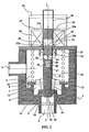
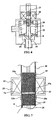
- Vorrichtung zur Regelung eines Fluids mit zweifacher Sicherheit, mit einem Regelventil (6) und einem Sicherheitsventil (7), die in Reihe in einer Fluidpassage angeordnet sind und in demselben Körper der Vorrichtung (1) untergebracht sind, wobei das Sicherheitsventil (7) eine Erregerspule (20) aufweist, die durch einen magnetischen Erregerkreis (22, 19) einen beweglichen Sicherheitsmagnetkern (18), der mechanisch mit einem Sicherheitsverschlussteil (8) verbunden ist, anregt, wobei die Aktivierung der Erregerspule (20) eine vollständige Öffnung des Sicherheitsverschlussteiles (8) gestattet, während eine Deaktivierung der Erregerspule (20) eine Rückkehr des Sicherheitsverschlussteiles (8) in den Zustand vollständigen Schließens unter Wirkung einer Sicherheitsschließfeder (13) bewirkt, wobei das Regelventil (6) einen Regelverschlussteil (14) aufweist, der durch eine Regelfeder (17) in Richtung seiner vollständigen Schließstellung beaufschlagt ist und über ein elektromagnetisches Kopplungsmittel (20, 22, 19, 18) mit einem Linear-Betätigungsorgan (21) verbunden ist, das geeignet ist, seine Position in kontinuierlicher Weise längs eines geradlinigen Weges zwischen einer vollständigen Öffnung und einer kompletten Schließung zu regeln, wobei das elektromagnetische Kopplungsmittel die genannte Erregerspule (20) enthält, die, wenn sie aktiviert ist, durch den genannten magnetischen Erregerkreis (22, 19), der mit dem Linear-Betätigungsorgan (21) verbunden ist, einen beweglichen magnetischen Kopplungskern (18) beaufschlagt, der mit dem Regelverschlussteil (14) verbunden ist, wobei die genannte Erregerspule (20) und der genannte Erregerkreis (22) gleichzeitig an der Betätigung des Sicherheitsverschlussteiles (8) teilnehmen und an der Kopplung des Regelverschlussteiles (14) mit dem Linear-Betätigungsorgan (21), dadurch gekennzeichnet, daß:- der bewegliche Sicherheitsmagnetkern und der bewegliche Kopplungsmagnetkern ein und derselbe bewegliche Magnetkern (18) sind,- der Regelverschlussteil (14) und der Sicherheitsverschlussteil (8) auf einer gemeinsamen Verschiebungsachse (I-I) angeordnet sind,- der Sicherheitsverschlussteil (8) mechanisch mit dem beweglichen Magnetkern (18) mittels einer mechanischen, in einer Richtung wirkenden Sicherheitsverbindung (9) verbunden ist, die einen positiven Antrieb des Sicherheitsverschlussteiles (8) im Sinne dessen Öffnung sicherstellt, wobei sie gleichzeitig dem beweglichen Magnetkern (18) die Möglichkeit zur unabhängigen Verschiebung des Sicherheitsverschlussteiles (8) im Sinne dessen Schließung läßt,- der Regelverschlussteil (14) mechanisch mit dem beweglichen Magnetkern (18) mittels einer in einer Richtung wirkenden Regelverbindung (16, 24, 25, 26) verbunden ist, die einen positiven Antrieb des Regelverschlussteiles (14) im Sinne dessen Öffnung sicherstellt und gleichzeitig dem beweglichen Magnetkern (18) eine Möglichkeit zur unabhängigen Verschiebung des Regelverschlussteiles (14) im Sinne dessen Schließung läßt.
- Vorrichtung nach Anspruch 1, dadurch gekennzeichnet, daß die Sicherheitsschließfeder (13) zwischen den Körper der Vorrichtung (1) und den Sicherheitsverschlussteil (8) eingesetzt ist.
- Vorrichtung nach einem der Ansprüche 1 oder 2, dadurch gekennzeichnet, daß die Regelfeder (17) zwischen den Sicherheitsverschlussteil (8) und den Regelverschlussteil (14) eingesetzt ist.
- Vorrichtung nach irgendeinem der Ansprüche 1 bis 3, dadurch gekennzeichnet, daß der Regelverschlussteil (14) mechanisch mit dem beweglichen Magnetkern (18) mittels einer axialen Stange (24) verbunden ist, die mit dem beweglichen Magnetkern (18) zusammenhängt und einen Kopf (25) trägt, der in einem axialen Raum (26) gleitet, der durch einen axialen Kern (16) begrenzt ist, der mit dem Regelverschlussteil (14) verbunden ist, wobei der Kopf (25) axial in dem axialen Raum (26) zwischen dessen Boden (27) und dem Anschlag (28) gleiten kann.
- Vorrichtung nach Anspruch 4, dadurch gekennzeichnet, daß die axiale Stange (24) und der axiale Raum (26) so dimensioniert sind, daß, wenn der Sicherheitsverschlussteil (8) und der Regelverschlussteil (14) geschlossen sind, sich der Kopf (25) in einer axialen Position zwischen dem axialen Raum (26) befindet, derart, daß sich der Sicherheitsverschlussteil (8) vor dem Regelverschlussteil (14) öffnet.
- Vorrichtung nach einem der Ansprüche 4 oder 5, dadurch gekennzeichnet, daß eine Kompressionsfeder (29) zwischen den Kopf (25) und den Boden (27) des axialen Raumes (26) eingesetzt ist, um den Kopf (25) und dem beweglichen Magnetkern (18) in Richtung zum Regelverschlussteil (14) zu stoßen.
- Vorrichtung nach irgendeinem der Ansprüche 1 bis 6, dadurch gekennzeichnet, daß der Sicherheitsverschlussteil (8) mechanisch mit dem beweglichen Magnetkern (18) mittels eines axialen Blindrohres (9) verbunden ist, wobei das offene Ende des axialen Blindrohres (9) mit dem Sicherheitsverschlussteil (8) zusammenhängend ist, wobei der Körper des axialen Blindrohres (9) gleitend in dem Körper der Vorrichtung (1) mittels einer Führungshülse (12) gleitend geführt ist, wobei der bewegliche Magnetkörper (18) in dem axialen Blindrohr (9) gleitend in Eingriff steht.
- Vorrichtung nach Anspruch 7, dadurch gekennzeichnet, daß das axiale Blindrohr (9) aus nicht-magnetischen Materialien ist.
- Vorrichtung nach einem der Ansprüche 7 oder 8, dadurch gekennzeichnet, daß die Mittel zur Führung des Rohres einen Ring (12) aus Kunststoffmaterial mit geringem Reibungskoeffizienten aufweisen, der mit dem Körper der Vorrichtung (1) zusammenhaltend ausgebildet ist und der mit der äußeren Seitenfläche des axialen Blindrohres in Kontakt steht.
- Vorrichtung nach irgendeinem der Ansprüche 7 bis 9, dadurch gekennzeichnet, daß das offene Ende des axialen Blindrohres (9) eine radiale ringförmige Lippe (10) enthält, unter der der Sicherheitsverschlussteil (8) gegenüberliegend zu einem Sicherheitssitz (11) in dichtender Weise komprimiert ist.
- Vorrichtung nach irgendeinem der Ansprüche 7 bis 10, dadurch gekennzeichnet, daß:- die Erregerspule (20) rings um eine gemeinsame Verschiebungsachse (I-I) des Körpers der Vorrichtung (1) angeordnet ist,- der magnetische Erregerkreis einen festen magnetischen Teil (22) mit einem proximalen Magnetpol (22a) und einem distalen Magnetpol (22b) auf beiden Seiten der Erregerspule (20) hat und einen magnetischen Antriebskern (19) enthält, der axial in der Erregerspule (20) gleitet und durch das Linear-Betätigungsorgan (21) angetrieben ist, wobei der magnetische Antriebskern (19) eine distale Fläche (19a) in Bezug zu einer proximalen Fläche (18a) des beweglichen Magnetkernes (18) hat.
- Vorrichtung nach Anspruch 11, dadurch gekennzeichnet, daß der proximale Magnetpol (22a) und/oder der distale Magnetpol (22b) jeweils durch einen zylindrischen koaxialen Teil des Magnetkreises in Verlängerung der Erregerspule (20) gebildet sind.
- Vorrichtung nach einem der Ansprüche 11 oder 12, dadurch gekennzeichnet, daß die Magnetpole (22a, 22b) derart angeordnet sind, daß die distale Fläche (19a) des magnetischen Antriebskernes (19) permanent zwischen den Magnetpolen (22a, 22b) längs des gesamten Verschiebeweges des Linear-Betätigungsorgans (21) ist.
- Vorrichtung nach irgendeinem der Ansprüche 11 bis 13, dadurch gekennzeichnet, daß ein dichter Glockenmotor (30) axial in dichtender Weise mit der Erregerspule (20) in Eingriff steht und das axiale Blindrohr (9) und den magnetischen Antriebskern (19) für ein axiales Gleiten aufnimmt.
- Vorrichtung nach irgendeinem der Ansprüche 1 bis 14, dadurch gekennzeichnet, daß der Regelverschlussteil (14) für ein axiales Gleiten durch seitliche Führungsmittel (32-34) geführt ist.
Applications Claiming Priority (2)
| Application Number | Priority Date | Filing Date | Title |
|---|---|---|---|
| FR0410284A FR2875573B1 (fr) | 2004-09-22 | 2004-09-22 | Vanne de regulation a double securite |
| PCT/FR2005/002345 WO2006032787A1 (fr) | 2004-09-22 | 2005-09-22 | Vanne de regulation a double securite |
Publications (2)
| Publication Number | Publication Date |
|---|---|
| EP1792111A1 EP1792111A1 (de) | 2007-06-06 |
| EP1792111B1 true EP1792111B1 (de) | 2008-01-30 |
Family
ID=34949891
Family Applications (1)
| Application Number | Title | Priority Date | Filing Date |
|---|---|---|---|
| EP05805803A Not-in-force EP1792111B1 (de) | 2004-09-22 | 2005-09-22 | Doppelschutzregelventil |
Country Status (6)
| Country | Link |
|---|---|
| EP (1) | EP1792111B1 (de) |
| CN (1) | CN100561028C (de) |
| AT (1) | ATE385302T1 (de) |
| DE (1) | DE602005004620T2 (de) |
| FR (1) | FR2875573B1 (de) |
| WO (1) | WO2006032787A1 (de) |
Cited By (2)
| Publication number | Priority date | Publication date | Assignee | Title |
|---|---|---|---|---|
| WO2011035966A1 (de) * | 2009-09-22 | 2011-03-31 | Robert Bosch Gmbh | Rückschlagventil mit zwei schliesskörpern |
| WO2017212864A1 (ja) * | 2016-06-06 | 2017-12-14 | 株式会社デンソー | 減圧装置 |
Families Citing this family (9)
| Publication number | Priority date | Publication date | Assignee | Title |
|---|---|---|---|---|
| DE102006036294A1 (de) * | 2006-08-03 | 2008-02-07 | Inter Control Hermann Köhler Elektrik GmbH & Co. KG | Gasventil und Verfahren zur Ansteuerung eines Gasventils |
| GB0723827D0 (en) * | 2007-12-06 | 2008-01-16 | Kohler Mira Ltd | Flow control valve |
| ES1068058Y (es) * | 2008-05-02 | 2008-11-01 | Coprecitec Sl | Grupo distribuidor de gas para un aparato de coccion |
| CN102133867A (zh) * | 2011-03-31 | 2011-07-27 | 韦良东 | 一种汽车碰撞进水时电路自动保护装置 |
| ITMI20121823A1 (it) * | 2012-10-26 | 2014-04-27 | Controlling Saving Energy Italia S R L | Termostato |
| JP6598153B2 (ja) * | 2015-10-15 | 2019-10-30 | リンナイ株式会社 | 安全弁 |
| DE102015118963A1 (de) * | 2015-11-05 | 2017-05-11 | Knorr-Bremse Systeme für Nutzfahrzeuge GmbH | Druckbegrenzungsventil |
| CN108266538B (zh) * | 2018-02-14 | 2024-02-09 | 珠海宝银智能科技有限公司 | 一种液化气瓶复合双自截止阀门及物联网控制系统 |
| CN109519584A (zh) * | 2018-09-12 | 2019-03-26 | 太重集团榆次液压工业(济南)有限公司 | 采用直线步进电机的电动主副油箱转换阀及使用方法 |
Family Cites Families (4)
| Publication number | Priority date | Publication date | Assignee | Title |
|---|---|---|---|---|
| PT1106923E (pt) * | 1999-12-02 | 2006-09-29 | Sit La Precisa Spa | Unidade de valvula para controlo do fornecimento de um gas combustivel |
| IT1309954B1 (it) * | 1999-12-30 | 2002-02-05 | Lucio Berto | Struttura di valvola di sicurezza particolarmente per gas. |
| FR2821915B1 (fr) * | 2001-03-06 | 2004-03-05 | App S Electro Mecaniques Du Fa | Dispositif de commande et de securite de debit gazeux |
| EP1323966A1 (de) * | 2001-12-21 | 2003-07-02 | G. Kromschröder Aktiengesellschaft | Vorrichtung und Verfahren zum Regeln und Absperren eines Fluidstromes |
-
2004
- 2004-09-22 FR FR0410284A patent/FR2875573B1/fr not_active Expired - Fee Related
-
2005
- 2005-09-22 CN CNB2005800337724A patent/CN100561028C/zh not_active Expired - Fee Related
- 2005-09-22 WO PCT/FR2005/002345 patent/WO2006032787A1/fr active IP Right Grant
- 2005-09-22 DE DE602005004620T patent/DE602005004620T2/de active Active
- 2005-09-22 AT AT05805803T patent/ATE385302T1/de not_active IP Right Cessation
- 2005-09-22 EP EP05805803A patent/EP1792111B1/de not_active Not-in-force
Cited By (2)
| Publication number | Priority date | Publication date | Assignee | Title |
|---|---|---|---|---|
| WO2011035966A1 (de) * | 2009-09-22 | 2011-03-31 | Robert Bosch Gmbh | Rückschlagventil mit zwei schliesskörpern |
| WO2017212864A1 (ja) * | 2016-06-06 | 2017-12-14 | 株式会社デンソー | 減圧装置 |
Also Published As
| Publication number | Publication date |
|---|---|
| WO2006032787A1 (fr) | 2006-03-30 |
| CN101036013A (zh) | 2007-09-12 |
| EP1792111A1 (de) | 2007-06-06 |
| FR2875573B1 (fr) | 2006-11-03 |
| DE602005004620D1 (de) | 2008-03-20 |
| DE602005004620T2 (de) | 2009-01-29 |
| FR2875573A1 (fr) | 2006-03-24 |
| ATE385302T1 (de) | 2008-02-15 |
| CN100561028C (zh) | 2009-11-18 |
| WO2006032787A8 (fr) | 2007-04-26 |
Similar Documents
| Publication | Publication Date | Title |
|---|---|---|
| EP1792111B1 (de) | Doppelschutzregelventil | |
| EP2045496B1 (de) | Klappenschütze mit ausgeglichenem Druck | |
| EP1366317B1 (de) | Steuervorrichtung | |
| CA1325577C (fr) | Microelectrovanne de commutation a une seule membrane | |
| WO1987006320A1 (fr) | Soupape ou vanne fonctionnant sans frottement | |
| EP2921753A1 (de) | Raumfahrt-Magnetventil für kryogenes Hochdruckgas | |
| FR2954447A1 (fr) | Electrovanne et installation d'assistance de conduite equipee d'au moins une telle electrovanne | |
| FR2998025A1 (fr) | Vanne | |
| FR2529288A1 (fr) | Dispositif d'electroaimant et son application a la commande de soupapes | |
| EP0682615B1 (de) | Proportionales elektromagnetisch gesteuertes druckluftventil | |
| EP3026310B1 (de) | Elektromagnetisches Ventil für kryogenes Hochdruckgas | |
| EP2927547B1 (de) | Mini-schnellverschluss-magnetventil | |
| EP3514424B1 (de) | Bistabiles elektromagnetventil mit röhrenförmiger konfiguration mit axial fluchtendem ein- und ausgang | |
| FR2767221A1 (fr) | Disjoncteur a auto-soufflage et a compression reduite | |
| EP3098403B1 (de) | Vorrichtung zur steuerung der zufuhr einer unter druck stehenden flüssigkeit | |
| EP3096053B1 (de) | Kryogenes elektromagnetisches autoklavenventil für trägerrakete | |
| FR2756900A1 (fr) | Vanne distributrice | |
| CA2429217C (fr) | Dispositif de decharge brusque d'air avec conduite d'ejection amelioree | |
| EP0752152B1 (de) | Magnetischer betätiger mit mehrfach luftspalten | |
| FR2847644A1 (fr) | Soupape a commande par solenoide | |
| EP0736882A1 (de) | Steuervorrichtung mit Elektromagnet mit Kern ohne Reibung und Verwendung bei Ventilen mit Kontinusteuerung | |
| EP0000850B1 (de) | Kraftverstärkungs-Mechanismus und damit versehenes Absperrventil | |
| EP3728916A1 (de) | Elektroventileinrichtung | |
| WO2002069067A1 (fr) | Reducteur de pression equilibre pour des gaz haute pression | |
| FR3022317A1 (fr) | Vanne a trois voies comportant un noyau en translation |
Legal Events
| Date | Code | Title | Description |
|---|---|---|---|
| PUAI | Public reference made under article 153(3) epc to a published international application that has entered the european phase |
Free format text: ORIGINAL CODE: 0009012 |
|
| 17P | Request for examination filed |
Effective date: 20070329 |
|
| AK | Designated contracting states |
Kind code of ref document: A1 Designated state(s): AT BE BG CH CY CZ DE DK EE ES FI FR GB GR HU IE IS IT LI LT LU LV MC NL PL PT RO SE SI SK TR |
|
| GRAP | Despatch of communication of intention to grant a patent |
Free format text: ORIGINAL CODE: EPIDOSNIGR1 |
|
| DAX | Request for extension of the european patent (deleted) | ||
| GRAS | Grant fee paid |
Free format text: ORIGINAL CODE: EPIDOSNIGR3 |
|
| GRAA | (expected) grant |
Free format text: ORIGINAL CODE: 0009210 |
|
| RIN1 | Information on inventor provided before grant (corrected) |
Inventor name: CHAUMONTET, MICHAEL Inventor name: BOUCHANKOUK, AZIZ |
|
| AK | Designated contracting states |
Kind code of ref document: B1 Designated state(s): AT BE BG CH CY CZ DE DK EE ES FI FR GB GR HU IE IS IT LI LT LU LV MC NL PL PT RO SE SI SK TR |
|
| REG | Reference to a national code |
Ref country code: GB Ref legal event code: FG4D Free format text: NOT ENGLISH |
|
| REG | Reference to a national code |
Ref country code: CH Ref legal event code: EP |
|
| REG | Reference to a national code |
Ref country code: IE Ref legal event code: FG4D Free format text: LANGUAGE OF EP DOCUMENT: FRENCH |
|
| REF | Corresponds to: |
Ref document number: 602005004620 Country of ref document: DE Date of ref document: 20080320 Kind code of ref document: P |
|
| GBT | Gb: translation of ep patent filed (gb section 77(6)(a)/1977) |
Effective date: 20080430 |
|
| PG25 | Lapsed in a contracting state [announced via postgrant information from national office to epo] |
Ref country code: IS Free format text: LAPSE BECAUSE OF FAILURE TO SUBMIT A TRANSLATION OF THE DESCRIPTION OR TO PAY THE FEE WITHIN THE PRESCRIBED TIME-LIMIT Effective date: 20080530 Ref country code: FI Free format text: LAPSE BECAUSE OF FAILURE TO SUBMIT A TRANSLATION OF THE DESCRIPTION OR TO PAY THE FEE WITHIN THE PRESCRIBED TIME-LIMIT Effective date: 20080130 Ref country code: ES Free format text: LAPSE BECAUSE OF FAILURE TO SUBMIT A TRANSLATION OF THE DESCRIPTION OR TO PAY THE FEE WITHIN THE PRESCRIBED TIME-LIMIT Effective date: 20080511 |
|
| PG25 | Lapsed in a contracting state [announced via postgrant information from national office to epo] |
Ref country code: AT Free format text: LAPSE BECAUSE OF FAILURE TO SUBMIT A TRANSLATION OF THE DESCRIPTION OR TO PAY THE FEE WITHIN THE PRESCRIBED TIME-LIMIT Effective date: 20080130 |
|
| PG25 | Lapsed in a contracting state [announced via postgrant information from national office to epo] |
Ref country code: PL Free format text: LAPSE BECAUSE OF FAILURE TO SUBMIT A TRANSLATION OF THE DESCRIPTION OR TO PAY THE FEE WITHIN THE PRESCRIBED TIME-LIMIT Effective date: 20080130 Ref country code: LV Free format text: LAPSE BECAUSE OF FAILURE TO SUBMIT A TRANSLATION OF THE DESCRIPTION OR TO PAY THE FEE WITHIN THE PRESCRIBED TIME-LIMIT Effective date: 20080130 Ref country code: PT Free format text: LAPSE BECAUSE OF FAILURE TO SUBMIT A TRANSLATION OF THE DESCRIPTION OR TO PAY THE FEE WITHIN THE PRESCRIBED TIME-LIMIT Effective date: 20080630 Ref country code: SI Free format text: LAPSE BECAUSE OF FAILURE TO SUBMIT A TRANSLATION OF THE DESCRIPTION OR TO PAY THE FEE WITHIN THE PRESCRIBED TIME-LIMIT Effective date: 20080130 |
|
| REG | Reference to a national code |
Ref country code: IE Ref legal event code: FD4D |
|
| PG25 | Lapsed in a contracting state [announced via postgrant information from national office to epo] |
Ref country code: IE Free format text: LAPSE BECAUSE OF FAILURE TO SUBMIT A TRANSLATION OF THE DESCRIPTION OR TO PAY THE FEE WITHIN THE PRESCRIBED TIME-LIMIT Effective date: 20080130 Ref country code: SE Free format text: LAPSE BECAUSE OF FAILURE TO SUBMIT A TRANSLATION OF THE DESCRIPTION OR TO PAY THE FEE WITHIN THE PRESCRIBED TIME-LIMIT Effective date: 20080430 Ref country code: SK Free format text: LAPSE BECAUSE OF FAILURE TO SUBMIT A TRANSLATION OF THE DESCRIPTION OR TO PAY THE FEE WITHIN THE PRESCRIBED TIME-LIMIT Effective date: 20080130 Ref country code: CZ Free format text: LAPSE BECAUSE OF FAILURE TO SUBMIT A TRANSLATION OF THE DESCRIPTION OR TO PAY THE FEE WITHIN THE PRESCRIBED TIME-LIMIT Effective date: 20080130 Ref country code: DK Free format text: LAPSE BECAUSE OF FAILURE TO SUBMIT A TRANSLATION OF THE DESCRIPTION OR TO PAY THE FEE WITHIN THE PRESCRIBED TIME-LIMIT Effective date: 20080130 |
|
| PG25 | Lapsed in a contracting state [announced via postgrant information from national office to epo] |
Ref country code: RO Free format text: LAPSE BECAUSE OF FAILURE TO SUBMIT A TRANSLATION OF THE DESCRIPTION OR TO PAY THE FEE WITHIN THE PRESCRIBED TIME-LIMIT Effective date: 20080130 |
|
| PLBE | No opposition filed within time limit |
Free format text: ORIGINAL CODE: 0009261 |
|
| STAA | Information on the status of an ep patent application or granted ep patent |
Free format text: STATUS: NO OPPOSITION FILED WITHIN TIME LIMIT |
|
| 26N | No opposition filed |
Effective date: 20081031 |
|
| PG25 | Lapsed in a contracting state [announced via postgrant information from national office to epo] |
Ref country code: LT Free format text: LAPSE BECAUSE OF FAILURE TO SUBMIT A TRANSLATION OF THE DESCRIPTION OR TO PAY THE FEE WITHIN THE PRESCRIBED TIME-LIMIT Effective date: 20080130 |
|
| BERE | Be: lapsed |
Owner name: G. CARTIER TECHNOLOGIES Effective date: 20080930 |
|
| PG25 | Lapsed in a contracting state [announced via postgrant information from national office to epo] |
Ref country code: EE Free format text: LAPSE BECAUSE OF FAILURE TO SUBMIT A TRANSLATION OF THE DESCRIPTION OR TO PAY THE FEE WITHIN THE PRESCRIBED TIME-LIMIT Effective date: 20080130 Ref country code: MC Free format text: LAPSE BECAUSE OF NON-PAYMENT OF DUE FEES Effective date: 20080930 Ref country code: BG Free format text: LAPSE BECAUSE OF FAILURE TO SUBMIT A TRANSLATION OF THE DESCRIPTION OR TO PAY THE FEE WITHIN THE PRESCRIBED TIME-LIMIT Effective date: 20080430 |
|
| PG25 | Lapsed in a contracting state [announced via postgrant information from national office to epo] |
Ref country code: CY Free format text: LAPSE BECAUSE OF FAILURE TO SUBMIT A TRANSLATION OF THE DESCRIPTION OR TO PAY THE FEE WITHIN THE PRESCRIBED TIME-LIMIT Effective date: 20080130 Ref country code: BE Free format text: LAPSE BECAUSE OF NON-PAYMENT OF DUE FEES Effective date: 20080930 |
|
| REG | Reference to a national code |
Ref country code: CH Ref legal event code: PL |
|
| PG25 | Lapsed in a contracting state [announced via postgrant information from national office to epo] |
Ref country code: HU Free format text: LAPSE BECAUSE OF FAILURE TO SUBMIT A TRANSLATION OF THE DESCRIPTION OR TO PAY THE FEE WITHIN THE PRESCRIBED TIME-LIMIT Effective date: 20080731 Ref country code: LU Free format text: LAPSE BECAUSE OF NON-PAYMENT OF DUE FEES Effective date: 20080922 |
|
| PG25 | Lapsed in a contracting state [announced via postgrant information from national office to epo] |
Ref country code: CH Free format text: LAPSE BECAUSE OF NON-PAYMENT OF DUE FEES Effective date: 20090930 Ref country code: LI Free format text: LAPSE BECAUSE OF NON-PAYMENT OF DUE FEES Effective date: 20090930 Ref country code: GR Free format text: LAPSE BECAUSE OF FAILURE TO SUBMIT A TRANSLATION OF THE DESCRIPTION OR TO PAY THE FEE WITHIN THE PRESCRIBED TIME-LIMIT Effective date: 20080501 |
|
| PGFP | Annual fee paid to national office [announced via postgrant information from national office to epo] |
Ref country code: NL Payment date: 20140915 Year of fee payment: 10 |
|
| PGFP | Annual fee paid to national office [announced via postgrant information from national office to epo] |
Ref country code: TR Payment date: 20140915 Year of fee payment: 10 Ref country code: GB Payment date: 20140930 Year of fee payment: 10 |
|
| PGFP | Annual fee paid to national office [announced via postgrant information from national office to epo] |
Ref country code: IT Payment date: 20140926 Year of fee payment: 10 |
|
| PGFP | Annual fee paid to national office [announced via postgrant information from national office to epo] |
Ref country code: FR Payment date: 20140925 Year of fee payment: 10 Ref country code: DE Payment date: 20140930 Year of fee payment: 10 |
|
| REG | Reference to a national code |
Ref country code: DE Ref legal event code: R119 Ref document number: 602005004620 Country of ref document: DE |
|
| PG25 | Lapsed in a contracting state [announced via postgrant information from national office to epo] |
Ref country code: IT Free format text: LAPSE BECAUSE OF NON-PAYMENT OF DUE FEES Effective date: 20150922 |
|
| GBPC | Gb: european patent ceased through non-payment of renewal fee |
Effective date: 20150922 |
|
| REG | Reference to a national code |
Ref country code: NL Ref legal event code: MM Effective date: 20151001 |
|
| REG | Reference to a national code |
Ref country code: FR Ref legal event code: ST Effective date: 20160531 |
|
| PG25 | Lapsed in a contracting state [announced via postgrant information from national office to epo] |
Ref country code: GB Free format text: LAPSE BECAUSE OF NON-PAYMENT OF DUE FEES Effective date: 20150922 Ref country code: DE Free format text: LAPSE BECAUSE OF NON-PAYMENT OF DUE FEES Effective date: 20160401 |
|
| PG25 | Lapsed in a contracting state [announced via postgrant information from national office to epo] |
Ref country code: NL Free format text: LAPSE BECAUSE OF NON-PAYMENT OF DUE FEES Effective date: 20151001 Ref country code: FR Free format text: LAPSE BECAUSE OF NON-PAYMENT OF DUE FEES Effective date: 20150930 |
|
| PG25 | Lapsed in a contracting state [announced via postgrant information from national office to epo] |
Ref country code: TR Free format text: LAPSE BECAUSE OF NON-PAYMENT OF DUE FEES Effective date: 20150922 |