EP1790506A1 - Suspension spring adjusting apparatus of hydraulic shock absorber - Google Patents
Suspension spring adjusting apparatus of hydraulic shock absorber Download PDFInfo
- Publication number
- EP1790506A1 EP1790506A1 EP06012875A EP06012875A EP1790506A1 EP 1790506 A1 EP1790506 A1 EP 1790506A1 EP 06012875 A EP06012875 A EP 06012875A EP 06012875 A EP06012875 A EP 06012875A EP 1790506 A1 EP1790506 A1 EP 1790506A1
- Authority
- EP
- European Patent Office
- Prior art keywords
- spring adjusting
- case
- harness
- spring
- shock absorber
- Prior art date
- Legal status (The legal status is an assumption and is not a legal conclusion. Google has not performed a legal analysis and makes no representation as to the accuracy of the status listed.)
- Withdrawn
Links
Images






Classifications
-
- F—MECHANICAL ENGINEERING; LIGHTING; HEATING; WEAPONS; BLASTING
- F16—ENGINEERING ELEMENTS AND UNITS; GENERAL MEASURES FOR PRODUCING AND MAINTAINING EFFECTIVE FUNCTIONING OF MACHINES OR INSTALLATIONS; THERMAL INSULATION IN GENERAL
- F16F—SPRINGS; SHOCK-ABSORBERS; MEANS FOR DAMPING VIBRATION
- F16F9/00—Springs, vibration-dampers, shock-absorbers, or similarly-constructed movement-dampers using a fluid or the equivalent as damping medium
- F16F9/32—Details
- F16F9/3207—Constructional features
-
- B—PERFORMING OPERATIONS; TRANSPORTING
- B60—VEHICLES IN GENERAL
- B60G—VEHICLE SUSPENSION ARRANGEMENTS
- B60G15/00—Resilient suspensions characterised by arrangement, location or type of combined spring and vibration damper, e.g. telescopic type
- B60G15/08—Resilient suspensions characterised by arrangement, location or type of combined spring and vibration damper, e.g. telescopic type having fluid spring
- B60G15/12—Resilient suspensions characterised by arrangement, location or type of combined spring and vibration damper, e.g. telescopic type having fluid spring and fluid damper
- B60G15/14—Resilient suspensions characterised by arrangement, location or type of combined spring and vibration damper, e.g. telescopic type having fluid spring and fluid damper the damper being connected to the stub axle and the spring being arranged around the damper
-
- B—PERFORMING OPERATIONS; TRANSPORTING
- B60—VEHICLES IN GENERAL
- B60G—VEHICLE SUSPENSION ARRANGEMENTS
- B60G17/00—Resilient suspensions having means for adjusting the spring or vibration-damper characteristics, for regulating the distance between a supporting surface and a sprung part of vehicle or for locking suspension during use to meet varying vehicular or surface conditions, e.g. due to speed or load
- B60G17/02—Spring characteristics, e.g. mechanical springs and mechanical adjusting means
- B60G17/027—Mechanical springs regulated by fluid means
- B60G17/0272—Mechanical springs regulated by fluid means the mechanical spring being a coil spring
-
- B—PERFORMING OPERATIONS; TRANSPORTING
- B60—VEHICLES IN GENERAL
- B60G—VEHICLE SUSPENSION ARRANGEMENTS
- B60G17/00—Resilient suspensions having means for adjusting the spring or vibration-damper characteristics, for regulating the distance between a supporting surface and a sprung part of vehicle or for locking suspension during use to meet varying vehicular or surface conditions, e.g. due to speed or load
- B60G17/02—Spring characteristics, e.g. mechanical springs and mechanical adjusting means
- B60G17/04—Spring characteristics, e.g. mechanical springs and mechanical adjusting means fluid spring characteristics
-
- B—PERFORMING OPERATIONS; TRANSPORTING
- B60—VEHICLES IN GENERAL
- B60G—VEHICLE SUSPENSION ARRANGEMENTS
- B60G2202/00—Indexing codes relating to the type of spring, damper or actuator
- B60G2202/30—Spring/Damper and/or actuator Units
- B60G2202/31—Spring/Damper and/or actuator Units with the spring arranged around the damper, e.g. MacPherson strut
- B60G2202/312—The spring being a wound spring
-
- B—PERFORMING OPERATIONS; TRANSPORTING
- B60—VEHICLES IN GENERAL
- B60G—VEHICLE SUSPENSION ARRANGEMENTS
- B60G2202/00—Indexing codes relating to the type of spring, damper or actuator
- B60G2202/30—Spring/Damper and/or actuator Units
- B60G2202/31—Spring/Damper and/or actuator Units with the spring arranged around the damper, e.g. MacPherson strut
- B60G2202/314—The spring being a pneumatic spring
-
- B—PERFORMING OPERATIONS; TRANSPORTING
- B60—VEHICLES IN GENERAL
- B60G—VEHICLE SUSPENSION ARRANGEMENTS
- B60G2204/00—Indexing codes related to suspensions per se or to auxiliary parts
- B60G2204/10—Mounting of suspension elements
- B60G2204/12—Mounting of springs or dampers
- B60G2204/128—Damper mount on vehicle body or chassis
-
- B—PERFORMING OPERATIONS; TRANSPORTING
- B60—VEHICLES IN GENERAL
- B60G—VEHICLE SUSPENSION ARRANGEMENTS
- B60G2204/00—Indexing codes related to suspensions per se or to auxiliary parts
- B60G2204/10—Mounting of suspension elements
- B60G2204/12—Mounting of springs or dampers
- B60G2204/129—Damper mount on wheel suspension or knuckle
-
- B—PERFORMING OPERATIONS; TRANSPORTING
- B60—VEHICLES IN GENERAL
- B60G—VEHICLE SUSPENSION ARRANGEMENTS
- B60G2204/00—Indexing codes related to suspensions per se or to auxiliary parts
- B60G2204/10—Mounting of suspension elements
- B60G2204/20—Mounting of accessories, e.g. pump, compressor
- B60G2204/202—Mounting of accessories, e.g. pump, compressor of cables
-
- B—PERFORMING OPERATIONS; TRANSPORTING
- B60—VEHICLES IN GENERAL
- B60G—VEHICLE SUSPENSION ARRANGEMENTS
- B60G2206/00—Indexing codes related to the manufacturing of suspensions: constructional features, the materials used, procedures or tools
- B60G2206/01—Constructional features of suspension elements, e.g. arms, dampers, springs
- B60G2206/011—Modular constructions
- B60G2206/0116—Integrated distribution control units with valves, accumulators, PCB's or the like
-
- B—PERFORMING OPERATIONS; TRANSPORTING
- B60—VEHICLES IN GENERAL
- B60G—VEHICLE SUSPENSION ARRANGEMENTS
- B60G2206/00—Indexing codes related to the manufacturing of suspensions: constructional features, the materials used, procedures or tools
- B60G2206/01—Constructional features of suspension elements, e.g. arms, dampers, springs
- B60G2206/40—Constructional features of dampers and/or springs
-
- B—PERFORMING OPERATIONS; TRANSPORTING
- B60—VEHICLES IN GENERAL
- B60G—VEHICLE SUSPENSION ARRANGEMENTS
- B60G2500/00—Indexing codes relating to the regulated action or device
- B60G2500/20—Spring action or springs
-
- B—PERFORMING OPERATIONS; TRANSPORTING
- B60—VEHICLES IN GENERAL
- B60G—VEHICLE SUSPENSION ARRANGEMENTS
- B60G2500/00—Indexing codes relating to the regulated action or device
- B60G2500/30—Height or ground clearance
Definitions
- the present invention relates to a suspension spring adjusting apparatus of a hydraulic shock absorber.
- a suspension spring adjusting apparatus of a hydraulic shock absorber there is a structure in which a piston rod is inserted to a cylinder, a spring adjusting jack is provided in an outer periphery of the cylinder, a jack chamber is provided in a spring adjusting case in which the spring adjusting jack is fixed to an outer periphery of the cylinder, a plunger is provided in the jack chamber.
- a pump supplying a hydraulic pressure to the jack chamber is installed in the spring adjusting case, a motor driving the pump is provided in the spring adjusting case, the motor is covered by a case cover attached to the spring adjusting case, and a suspension spring is interposed between a spring receiver supported to the plunger of the spring adjusting jack and a spring receiver provided in a piston rod side.
- Japanese Utility Model Publication No. 63-19204 discloses a structure wherein a vehicle body side is provided with a driving means (a motor or the like) for adjusting a damping force of a hydraulic shock absorber, and a mounting mating surface between the vehicle body and a cover (a seal cap) is sealed by a seal ring, at a time of covering the driving means for adjusting the damping force by the cover attached to the vehicle body side.
- a driving means a motor or the like
- the mounting boss is provided in a rising manner in the spring adjusting case, and the end surface forming the motor mounting seat surface of the mounting boss is worked in a flat shape, as the mounting structure of the motor to the spring adjusting case.
- An object of the present invention is to securely seal a mounting portion between a spring adjusting case and a case cover in a waterproof manner while easily working the spring adjusting case and the case cover, in a suspension spring adjusting apparatus of a hydraulic shock absorber.
- the present invention relates to a suspension spring adjusting apparatus of a hydraulic shock absorber comprising: a piston rod inserted to a cylinder; a spring adjusting jack provided in an outer periphery of the cylinder; a jack chamber provided in a spring adjusting case in which the spring adjusting jack is fixed to the outer periphery of the cylinder, wherein a plunger is provided in the jack chamber, a pump supplying a hydraulic pressure to the jack chamber is installed in the spring adjusting case, a motor driving the pump is provided in the spring adjusting case, and the motor is covered by a case cover attached to the spring adjusting case; and a suspension spring interposed between a spring receiver supported by the plunger of the spring adjusting jack and a spring receiver provided in a side of the piston rod.
- a mounting mating surface sealed by a seal material of the spring adjusting case and the case cover is formed in a flat surface shape.
- An outer peripheral edge of the case cover is provided with a skirt portion covering over an outer peripheral surface
- a hydraulic shock absorber 10 is structured, as shown in FIGS. 1 and 2, such that a hollow piston rod 12 is inserted to a cylinder 11, and a suspension spring 13 is interposed in outer side portions of the cylinder 11 and the piston rod 12.
- the cylinder 11 is provided with a vehicle body side mounting member 14, and the piston rod 12 is provided with an axle side mounting member 15.
- a spring adjusting jack 60A of a suspension spring adjusting apparatus 60 in detail mentioned below is provided in an outer peripheral portion of the cylinder 11, and a spring receiver 17 is supported thereto.
- a spring receiver 18 is fixed to the axle side mounting member 15 in the piston rod 12, the suspension spring 13 is interposed between the spring receiver 17 and the spring receiver 18, and a set length of the suspension spring 13 can be adjusted by the spring adjusting jack 60A.
- An elastic force of the suspension spring 13 absorbs an impact force which a vehicle receives from a road surface.
- Reference symbol 13A denotes a spring cover.
- the cylinder 11 is provided with a rod guide 21 through which the piston rod 12 passes.
- the cylinder 11 is provided with a bump stopper cap 22 in an outer side of the rod guide 21, and it is possible to regulate a maximum compressive stroke by bringing the bump stopper cap 22 into collision with a bump rubber 23 provided in the piston rod 12, at a time of peak compression.
- the cylinder 11 is provided with a rebound rubber 24 in an inner side of the rod guide 21.
- the hydraulic shock absorber 10 has a piston valve apparatus (a compression side and expansion side damping force generating apparatus) 30.
- the hydraulic shock absorber 10 suppresses an expanding and contracting vibration of the cylinder 11 and the piston rod 12 in accordance with an absorption of an impact force by the suspension spring 13, on the basis of a damping force generated by the piston valve apparatus 30.
- the piston valve apparatus 30 is structured such that a piston 31 is fixed to an end portion of the piston rod 12, an inner portion of the cylinder 11 is sectioned to a piston side oil chamber 33A in which the piston rod 12 is not accommodated, and a rod side oil chamber 33B in which the piston rod 12 is accommodated.
- a disc-like compression side damping valve 34 and a disc-like expansion side damping valve 35 are respectively provided in a compression side oil path and an expansion side oil path communicating between the piston side oil chamber 33A and the rod side oil chamber 33B provided in the piston 31.
- the piston valve apparatus 30 has a damping force adjusting apparatus 40.
- the damping force adjusting apparatus 40 can adjust an expansion side damping force by moving forward and backward an adjusting rod 42 inserted to a hollow portion of the piston rod 12 by means of a motor 41 installed in the axle side mounting member 15, and adjusting an opening area of a bypass oil path 43 provided in the hollow portion of the piston rod 12 in such a manner as to communicate the piston side oil chamber 33A with the rod side oil chamber 33B by means of a leading end needle valve 42A of the adjusting rod 42.
- the hydraulic shock absorber 10 has a base valve apparatus (a compression side damping force generating apparatus) 50.
- the base valve apparatus 50 is provided with a partition wall member 51 in an inner portion of the cylinder 11, is provided with a reservoir chamber 52 sectioned from the piston side oil chamber 33A by the partition wall member 51, and defines a gas chamber 52A at the back of the reservoir chamber 52 by means of a rubber-like diaphragm 53 fitted to an outer periphery in a side of the reservoir chamber 52 of the partition wall member 51.
- the base valve apparatus 50 is provided with a disc-like expansion side damping valve (a check valve) 54 and a disc-like compression side damping valve 55 respectively in an expansion side oil path and a compression side oil path communicating between the piston side oil chamber 33A and the reservoir chamber 52 provided in the partition wall member 51.
- a disc-like expansion side damping valve (a check valve) 54 and a disc-like compression side damping valve 55 respectively in an expansion side oil path and a compression side oil path communicating between the piston side oil chamber 33A and the reservoir chamber 52 provided in the partition wall member 51.
- the hydraulic shock absorber 10 is provided with a communication path 56 communicating the piston side oil chamber 33A with the reservoir chamber 52 in the partition wall member 51, and is provided with a control rod 57 fitting the piston rod 12 to the communication path 56 via a small gap after compressing the piston rod 12 at a fixed stroke in the piston rod 12.
- a damping operation of the hydraulic shock absorber 10 is as follows.
- the oil at a volumetric capacity at which the piston rod 12 moves forward into the cylinder 11 is extruded to the reservoir chamber 52 from the piston side oil chamber 33A through the communication path 56 or the oil path of the partition wall member 51 so as to be compensated.
- the oil at a volumetric capacity at which the piston rod 12 moves backward from the cylinder 11 is returned to the piston side oil chamber 33A through the oil path of the partition wall member 51 or the communication path 56 from the reservoir 52 so as to be compensated.
- the suspension spring adjusting apparatus 60 is provided with a spring adjusting jack 60A in an outer periphery of the cylinder 11, as shown in FIGS. 1 to 6.
- the spring adjusting jack 60A is structured such that a jack chamber 62 is provided in a spring adjusting case 61 fixed to the outer periphery of the cylinder 11, a plunger 63 is slidably provided in the jack chamber 62, a pump 70 supplying a hydraulic pressure to the jack chamber 62 is installed in the spring adjusting case 61, a motor 80 driving the pump 70 is provided in the spring adjusting case 61, and the motor 80 is covered by a case cover 90 attached to the spring adjusting case 61.
- the suspension spring 13 is interposed between the spring receiver 17 supported to the plunger 63 of the spring adjusting jack 60A and the spring receiver 18 provided in the side of the piston rod 12, and a spring force of the suspension spring 13 can be adjusted by adjusting a set length of the suspension spring 13 on the basis of a vertical movement of the plunger 63 and the spring receiver 17 by means of the spring adjusting jack 60A.
- the spring adjusting jack 60A is structured, as shown in FIGS. 2 and 3, such that the sleeve 19 is fitted to an outer periphery of the cylinder 11, and is locked in an axial direction by a stop ring 11A (FIG. 2).
- the jack housing 61A of the spring adjusting case 61 is inserted and attached to the sleeve 19 via an O-ring 64, and is locked in an axial direction by a stop ring 19A (FIG. 3).
- the plunger 63 is slidably fitted to the jack chamber 62 between the sleeve 19 and the jack housing 61A via O-rings 63A and 63B (FIG. 3).
- Reference symbol 19B (FIG. 3) denotes a slidable end regulating stop ring of the plunger 63.
- the spring adjusting jack 60A is structured by uniting a structure provided with the spring receiver 17 in the plunger 63.
- the spring adjusting jack 60A has a pump 70 built-in the pump housing 61B of the spring adjusting case 61, as shown in FIG. 4.
- the pump 70 is structured, as shown in FIGS. 4 and 14, such that a tubular holder 71 is fixed to the pump housing 61B in accordance with a screw, and a drive shaft 73 is supported by a thrust bearing 72 provided in the holder 71.
- One end of the drive shaft 73 is formed as a hexagonal shaft 73A coupled to the motor 80, and a leveling nut 74 is screwed to the other end thread shaft 73B in such a manner as to pinch a rebound rubber 74A with respect to a flange 73C.
- a pin 75 is implanted in an outer periphery of the nut 74, and the pin 75 is locked into a linear guide groove 71A provided in an axial direction of an inner surface of the holder 71.
- a leveling piston 76 is slidably inserted to the pump chamber 70A of the pump housing 61B via an O-ring 76A, and the piston 76 is brought into collision with a leading end surface of the nut 74 so as to be supported by a back surface.
- the jack chamber 62 within the jack housing 61A and the pump chamber 70A within the pump housing 61B are communicated by a communication path 70B as shown in FIGS. 8 to 10.
- FIG. 8 to 10 In FIG.
- reference numeral 77 denotes a plug
- reference symbol 77A denotes an O-ring
- the spring adjusting jack 60A attaches the motor driving the pump 70 within a profile of a mounting mating surface 65 to the case cover 90 in the spring adjusting case 61.
- the motor 80 is structured, as shown in FIGS. 7A to 7C, such that a speed reducer 81 is integrally provided in a leading end side, and the hexagonal shaft 73A of the drive shaft 73 of the pump 70 is fitted and coupled to a hexagonal hole 82A provided in an output shaft 82 of the speed reducer 81.
- the motor 80 is provided with a mounting convex portion 83 protruding to an outer side from a terminal end side of the motor 80 in a direction along a motor shaft (not shown), and is provided with mounting bosses 84 arranged at two planar points which are orthogonal to an output shaft 82 of a speed reducer 81.
- the motor 80 is structured, as shown in FIG. 3 and 5, such that a motor mounting stay 85 is fixed to a motor mounting hole 66A (FIG. 8) of a mounting mating surface 65 of the spring adjusting case 61 by a mounting screw 85A, and a mounting holder 86 wound around a mounting convex portion 83 of the motor 80 is fixed to the mounting stay 85 by a locking screw 86A.
- the motor 80 is structured, as shown in FIGS. 3 and 4, such that the mounting bosses 84 at two points of the motor 80 are fixed to motor mounting holes 67A (FIG. 8) of the mounting seat surfaces 67 via a spacer 68 raised on the motor mounting seat surfaces 67 provided at two points of the mounting mating surface 65 of the spring adjusting case 61, by a mounting screw 87 and a washer 87A.
- the mounting screw 87 inserted to the mounting boss 84 of the motor 80 is screwed to the mounting hole 67A of the motor mounting seat surface 67 of the spring adjusting case 61 through the hollow portion of the spacer 68.
- the spring adjusting jack 60A is structured, as shown in FIGS. 2, 4 and 5, such that the motor 80 is covered by a closed-end case cover 90 attached to the spring adjusting case 61.
- a mounting mating surface 91 is aligned with a mounting mating surface 65 of the spring adjusting case 61, and a mounting screw 69 inserted to a mounting hole 65A (FIGS. 8 to 10) formed so as to pass through an external portion at five points in the mounting mating surface 65 of the spring adjusting case 61 is fixed to a mounting hole 92 (FIGS. 11A to 11C) provided in correspondence to the mounting mating surface 91 of the case cover 90, as shown in FIGS. 3 and 6.
- a plurality of harnesses 101 (a harness 101A for feeding power and a harness 101B for sensor) such as a feeder line, a signal line or the like connected to a control portion of the power source and the hydraulic shock absorber 10 are inserted to an inner portion of the spring adjusting case 61 from a harness insertion hole 110 provided in the spring adjusting case 61 so as to be connected to a socket 88 of the motor 80.
- a plurality of harnesses 101 structures a harness assembly 100 as shown in FIG. 15. The harnesses 101 are surrounded by a single tube 102 so as to be united into one bundle.
- reference numerals 103 and 104 denote a vehicle body side connecting socket previously fixed by caulking to one end side of the harness 101
- reference numeral 105 denotes a socket previously fixed to the other end side of the harness 101 so as to be connectable to the socket 88 of the motor 80.
- a harness 44 connected to the motor 41 of the damping force adjusting apparatus 40 is extended to inner and outer sides of the axle side mounting bracket 15.
- a mounting structure between the spring adjusting case 61 and the case cover 90, (B) a waterproof seal structure between the spring adjusting case 61 and the case cover 90, and (C) a harness insertion structure of the spring adjusting case 61 are made as follows.
- the spring adjusting jack 60A is structured such that when aligning the mounting mating surface 91 with the mounting mating surface 65 of the spring adjusting case 61 and fixing them by the mounting screw 69, the mounting mating surfaces 65 and 91 are sealed by an endless circumferential seal member 93 as shown in FIGS. 4 and 5, and the mounting screw 69 of the spring adjusting case 61 and the case cover 90 is arranged closer to an outer side of the case cover 90 than the seal member 93.
- the seal member 93 is loaded to an endless circumferential seal loading groove 91A extending along a profile of the mounting mating surface 91 within a surface of the mounting mating surface 91 of the case cover 90, and is compressed with respect to the mounting mating surface 65 of the spring adjusting case 61.
- the case cover 90 is structured such that the mounting mating surface 91 around the mounting hole 92 for the mounting screw 69 is formed so as to protrude to an inner side of the cover 90, and the circular arc-shaped seal loading groove 91A surrounding the mounting hole 92 is provided in the protruding portion of the mounting mating surface 91, and the circular arc-shaped seal loading groove 91A is smoothly connected to the seal loading groove 91A provided in the other portion of the mounting mating surface 91.
- the harness 101 connected to the motor 80 is inserted to the harness insertion hole 110 of the spring adjusting case 61 via a seal means 120 in detail mentioned below.
- the spring adjusting jack 60A is structured, as shown in FIGS. 4, 5 and 13, such that the mounting mating surfaces 65 and 91 sealed by the seal member 93 of the spring adjusting case 61 and the case cover 90 are formed in a flat surface shape, and an annular skirt portion 94 is provided in a protruding manner in an outer peripheral edge extending over an entire periphery around the mounting mating surface 91 of the case cover 90 (FIGS. 11A to 11C and 12).
- the annular skirt portion 94 surrounds an outer peripheral side surface around the mounting mating surface 65 of the spring adjusting case 61 via a gap A so as to cover over.
- a motor mounting seat surface 67 for a motor mounting spacer 68 provided in the spring adjusting case 61 is simultaneously worked in a flat surface shape which is flush formed with the mounting mating surface 65 for the case cover 90.
- the motor 80 is mounted to the mounting seat surface 67 of the spring adjusting case 61 via the spacer 68 as mentioned above.
- the mounting seat surface 66 for the motor mounting stay 85 provided in the spring adjusting case 61 is also simultaneously worked in a flat surface shape which is flush formed with the mounting mating surface 65 for the case cover 90.
- the spring adjusting jack 60A is structured, as shown in FIG. 5, such that the spring adjusting case 61 is previously provided with the harness insertion hole 110 having a larger aperture diameter than the outer size of the socket 105 in the harness assembly 100, in such a manner as to insert the socket 105 of the harness 101 to the spring adjusting case 61 under a state of being assembled in the outer periphery of the cylinder 11 from the outer side.
- the harness 101 of the harness assembly 100 is inserted to the harness insertion hole 110 via the seal means 120 in a watertight manner.
- the harness insertion hole 110 provided in the spring adjusting case 61 is constituted by a two-stage hole having a first hole 111 provided in the inner surface side of the spring adjusting case 61 and facing to the inner portion of the spring adjusting case 61, and a second hole 112 provided in the outer surface side of the spring adjusting case 61 and facing to the outer portion of the spring adjusting case 61, as shown in FIG. 16.
- the first hole 111 and the second hole 112 are constituted by a round hole and coaxially provided.
- a hole diameter D2 of the second hole 112 is larger than a hole diameter D1 of the first hole 111, and the hole diameter D1 of the first hole 111 is larger than the outer size of the socket 105.
- the seal means 120 is constituted by a harness guide 121 and a cap 122, as shown in FIGS. 15 and 16.
- the harness guide 121 is constituted by a rubber body approximately formed in a thick disc shape, as shown in FIG. 17.
- the harness guide 121 is provided with a flange 121A engaging with an outer edge of an outer end of the first hole 111 of the spring adjusting case 61, and a hook 121B locking to an outer edge of an inner end of the first hole 111, and is provided with a plurality of hole-shaped harness insertion paths 121C which can insert a plurality of harnesses 101, in a penetrating manner.
- the harness guide 121 When pressure inserting the harness guide 121 to which the harness 101 is inserted to the first hole 111, the harness guide 121 is compressed so as to reduce a diameter of the harness insertion path 121C, and inserts the harness 101 in a watertight manner while bringing an annular crimple 121D into pressure contact with the harness 101.
- the cap 122 is constituted by a rubber body approximately formed in an L shape, as shown in FIG. 18.
- the cap 122 is provided with a flange 122A elastically locking and attaching to an inner periphery of a back end of the second hole 112 of the spring adjusting case 61 in a base end side, is provided with a core metal 122B in an inner portion of the flange 122A, and is provided with a tube insertion path 122C in a leading end portion.
- the tube insertion path 122C is provided with a plurality of annular crimples 122D brought into pressure contact with the outer periphery of the tube 102 of the harness assembly 100, and can pressure insert and hold one end of the tube 102 in a waterproof manner.
- the harness assembly 100 is inserted and attached to the harness insertion hole 110 of the spring adjusting case 61 in the following manner.
Landscapes
- Engineering & Computer Science (AREA)
- Mechanical Engineering (AREA)
- General Engineering & Computer Science (AREA)
- Fluid-Damping Devices (AREA)
- Vehicle Body Suspensions (AREA)
Abstract
Description
- The present invention relates to a suspension spring adjusting apparatus of a hydraulic shock absorber.
- Conventionally, as a suspension spring adjusting apparatus of a hydraulic shock absorber, there is a structure in which a piston rod is inserted to a cylinder, a spring adjusting jack is provided in an outer periphery of the cylinder, a jack chamber is provided in a spring adjusting case in which the spring adjusting jack is fixed to an outer periphery of the cylinder, a plunger is provided in the jack chamber. A pump supplying a hydraulic pressure to the jack chamber is installed in the spring adjusting case, a motor driving the pump is provided in the spring adjusting case, the motor is covered by a case cover attached to the spring adjusting case, and a suspension spring is interposed between a spring receiver supported to the plunger of the spring adjusting jack and a spring receiver provided in a piston rod side.
- Alternatively,
Japanese Utility Model Publication No. 63-19204 - In the suspension spring adjusting apparatus of the hydraulic shock absorber, in the case that the structure described in the patent document 1 is employed as the seal structure between the spring adjusting case and the case cover, a high-pressure washing water of a high-pressure car wash or the like is directly brought into contact with an outer edge of the mounting mating surface between the spring adjusting case and the case cover, and the load of the direct intruding water against the seal ring becomes excessive.
- There can be considered a structure which prevents the high-pressure washing water from being directly brought into contact with the outer edge of the mounting mating surface between the spring adjusting case and the case cover, by faucet joining an annular protruding portion provided in an outer peripheral side of the case cover to a portion around an annular step portion provided in an outer peripheral surface of the spring adjusting case. In this case, the annular step portion and the annular protruding portion are worked respectively in the spring adjusting case and the case cover, and a fixed working precision is necessary for the faucet joint.
- In this case, in the conventional suspension spring adjusting apparatus of the hydraulic shock absorber, it is necessary that the mounting boss is provided in a rising manner in the spring adjusting case, and the end surface forming the motor mounting seat surface of the mounting boss is worked in a flat shape, as the mounting structure of the motor to the spring adjusting case.
- An object of the present invention is to securely seal a mounting portion between a spring adjusting case and a case cover in a waterproof manner while easily working the spring adjusting case and the case cover, in a suspension spring adjusting apparatus of a hydraulic shock absorber.
- The present invention relates to a suspension spring adjusting apparatus of a hydraulic shock absorber comprising: a piston rod inserted to a cylinder; a spring adjusting jack provided in an outer periphery of the cylinder; a jack chamber provided in a spring adjusting case in which the spring adjusting jack is fixed to the outer periphery of the cylinder, wherein a plunger is provided in the jack chamber, a pump supplying a hydraulic pressure to the jack chamber is installed in the spring adjusting case, a motor driving the pump is provided in the spring adjusting case, and the motor is covered by a case cover attached to the spring adjusting case; and a suspension spring interposed between a spring receiver supported by the plunger of the spring adjusting jack and a spring receiver provided in a side of the piston rod. A mounting mating surface sealed by a seal material of the spring adjusting case and the case cover is formed in a flat surface shape. An outer peripheral edge of the case cover is provided with a skirt portion covering over an outer peripheral surface of the spring adjusting case via a gap.
- The present invention will be more fully understood from the detailed description given below and from the accompanying drawings which should not be taken to be a limitation on the invention, but are for explanation and understanding only.
The drawings: - FIG. 1 is a perspective view showing a hydraulic shock absorber;
- FIG. 2 is a cross sectional view showing the hydraulic shock absorber;
- FIG. 3 is a front elevational view showing a motor mounting state to a spring adjusting case;
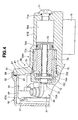
- FIG. 4 is a cross sectional view along a line IV-IV in FIG. 3;
- FIG. 5 is a cross sectional view schematically showing a cross section along a line V-V in FIG. 3;
- FIG. 6 is a back elevational view showing the spring adjusting case;
- FIGS. 7A to 7C show a motor, in which FIG. 7A is a front elevational view, FIG. 7B is a side elevational view and FIG. 7C is a back elevational view;
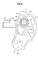
- FIG. 8 is a front elevational view showing the spring adjusting case;
- FIG. 9 is a cross sectional view showing a communication between a jack chamber of the spring adjusting case and a pump chamber;
- FIG. 10 is a cross sectional view showing the spring adjusting case;
- FIGS. 11A to 11C show a case cover, in which FIG. 11A is a cross sectional view, FIG. 11B is a front elevational view and FIG. 11C is a back elevational view;
- FIG. 12 is an enlarged cross sectional view showing a skirt portion of the case cover;
- FIG. 13 is a cross sectional view showing a mounting structure of the spring adjusting case and the case cover;
- FIG. 14 is a cross sectional view showing a pump;
- FIG. 15 is a plan view showing a harness assembly;
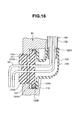
- FIG. 16 is a cross sectional view showing a harness insertion structure to the spring adjusting case;
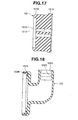
- FIG. 17 is a cross sectional view showing a harness guide; and
- FIG. 18 is a cross sectional view showing a cap.
- A
hydraulic shock absorber 10 is structured, as shown in FIGS. 1 and 2, such that ahollow piston rod 12 is inserted to acylinder 11, and asuspension spring 13 is interposed in outer side portions of thecylinder 11 and thepiston rod 12. - The
cylinder 11 is provided with a vehicle bodyside mounting member 14, and thepiston rod 12 is provided with an axleside mounting member 15. Aspring adjusting jack 60A of a suspensionspring adjusting apparatus 60 in detail mentioned below is provided in an outer peripheral portion of thecylinder 11, and aspring receiver 17 is supported thereto. Aspring receiver 18 is fixed to the axleside mounting member 15 in thepiston rod 12, thesuspension spring 13 is interposed between thespring receiver 17 and thespring receiver 18, and a set length of thesuspension spring 13 can be adjusted by thespring adjusting jack 60A. An elastic force of thesuspension spring 13 absorbs an impact force which a vehicle receives from a road surface.Reference symbol 13A denotes a spring cover. - The
cylinder 11 is provided with arod guide 21 through which thepiston rod 12 passes. In this case, thecylinder 11 is provided with abump stopper cap 22 in an outer side of therod guide 21, and it is possible to regulate a maximum compressive stroke by bringing thebump stopper cap 22 into collision with abump rubber 23 provided in thepiston rod 12, at a time of peak compression. Further, thecylinder 11 is provided with arebound rubber 24 in an inner side of therod guide 21. - The
hydraulic shock absorber 10 has a piston valve apparatus (a compression side and expansion side damping force generating apparatus) 30. The hydraulic shock absorber 10 suppresses an expanding and contracting vibration of thecylinder 11 and thepiston rod 12 in accordance with an absorption of an impact force by thesuspension spring 13, on the basis of a damping force generated by thepiston valve apparatus 30. - The
piston valve apparatus 30 is structured such that apiston 31 is fixed to an end portion of thepiston rod 12, an inner portion of thecylinder 11 is sectioned to a pistonside oil chamber 33A in which thepiston rod 12 is not accommodated, and a rodside oil chamber 33B in which thepiston rod 12 is accommodated. A disc-like compressionside damping valve 34 and a disc-like expansionside damping valve 35 are respectively provided in a compression side oil path and an expansion side oil path communicating between the pistonside oil chamber 33A and the rodside oil chamber 33B provided in thepiston 31. - The
piston valve apparatus 30 has a dampingforce adjusting apparatus 40. The dampingforce adjusting apparatus 40 can adjust an expansion side damping force by moving forward and backward an adjustingrod 42 inserted to a hollow portion of thepiston rod 12 by means of amotor 41 installed in the axleside mounting member 15, and adjusting an opening area of abypass oil path 43 provided in the hollow portion of thepiston rod 12 in such a manner as to communicate the pistonside oil chamber 33A with the rodside oil chamber 33B by means of a leadingend needle valve 42A of the adjustingrod 42. - The hydraulic shock absorber 10 has a base valve apparatus (a compression side damping force generating apparatus) 50. The
base valve apparatus 50 is provided with a partition wall member 51 in an inner portion of thecylinder 11, is provided with areservoir chamber 52 sectioned from the pistonside oil chamber 33A by the partition wall member 51, and defines agas chamber 52A at the back of thereservoir chamber 52 by means of a rubber-like diaphragm 53 fitted to an outer periphery in a side of thereservoir chamber 52 of the partition wall member 51. Thebase valve apparatus 50 is provided with a disc-like expansion side damping valve (a check valve) 54 and a disc-like compressionside damping valve 55 respectively in an expansion side oil path and a compression side oil path communicating between the pistonside oil chamber 33A and thereservoir chamber 52 provided in the partition wall member 51. - In order to apply a position dependency to the compression side damping force by the compression
side damping valve 55 of thebase valve apparatus 50, thehydraulic shock absorber 10 is provided with acommunication path 56 communicating the pistonside oil chamber 33A with thereservoir chamber 52 in the partition wall member 51, and is provided with acontrol rod 57 fitting thepiston rod 12 to thecommunication path 56 via a small gap after compressing thepiston rod 12 at a fixed stroke in thepiston rod 12. - Accordingly, a damping operation of the
hydraulic shock absorber 10 is as follows. -
- (a) When a moving speed of the
piston rod 12 is low, the oil in the pistonside oil chamber 33A moves to the rodside oil chamber 33B via abypass oil path 43 of thepiston rod 12, and the compression side damping force is obtained on the basis of a throttle resistance generated by theneedle valve 42A during this time. - (b) When the moving speed of the
piston rod 12 is middle or high, in a small stroke stage in which thecontrol rod 57 is not yet fitted to thecommunication path 56, in addition to the damping force in the item (a) mentioned above, the oil in the pistonside oil chamber 33A moves to the rodside oil chamber 33B through the compression side oil path of thepiston 31, and the compression side damping force is obtained by a deflecting deformation of thecompression side valve 34 during this time. - (c) When the moving speed of the
piston rod 12 is middle or high, in a large stroke stage in which thecontrol rod 57 is fitted to thecommunication path 56, in addition to the damping forces in the items (a) and (b) mentioned above, the oil in the pistonside oil chamber 33A moves to thereservoir chamber 52 through the compression side oil path of the partition wall member 51, and the compression side damping force is obtained by a deflecting deformation of thecompression side valve 55 during this time. - In this case, in the items (a) to (c) mentioned above, the oil at a volumetric capacity at which the
piston rod 12 moves forward into thecylinder 11 is extruded to thereservoir chamber 52 from the pistonside oil chamber 33A through thecommunication path 56 or the oil path of the partition wall member 51 so as to be compensated. -
- (a) When the moving speed of the
piston rod 12 is low, the oil in the rodside oil chamber 33B moves to the pistonside oil chamber 33A from thebypass oil path 43 of thepiston rod 12, and the expansion side damping force is obtained on the basis of a throttle resistance generated by theneedle valve 42A during this time. - (b) When the moving speed of the
piston rod 12 is middle or high, in addition to the damping force in the item (a) mentioned above, the oil in the rodside oil chamber 33B moves to the pistonside oil chamber 33A through the expansion side oil path of thepiston 31, and the expansion side damping force is obtained by a deflecting deformation of theexpansion side valve 35 during this time. - In this case, in the items (a) and (b) mentioned above, the oil at a volumetric capacity at which the
piston rod 12 moves backward from thecylinder 11 is returned to the pistonside oil chamber 33A through the oil path of the partition wall member 51 or thecommunication path 56 from thereservoir 52 so as to be compensated. - A description will be given below of a suspension
spring adjusting apparatus 60 of thehydraulic shock absorber 10. The suspensionspring adjusting apparatus 60 is provided with aspring adjusting jack 60A in an outer periphery of thecylinder 11, as shown in FIGS. 1 to 6. Thespring adjusting jack 60A is structured such that ajack chamber 62 is provided in aspring adjusting case 61 fixed to the outer periphery of thecylinder 11, aplunger 63 is slidably provided in thejack chamber 62, apump 70 supplying a hydraulic pressure to thejack chamber 62 is installed in thespring adjusting case 61, amotor 80 driving thepump 70 is provided in thespring adjusting case 61, and themotor 80 is covered by acase cover 90 attached to thespring adjusting case 61. Further, as mentioned above, thesuspension spring 13 is interposed between thespring receiver 17 supported to theplunger 63 of thespring adjusting jack 60A and thespring receiver 18 provided in the side of thepiston rod 12, and a spring force of thesuspension spring 13 can be adjusted by adjusting a set length of thesuspension spring 13 on the basis of a vertical movement of theplunger 63 and thespring receiver 17 by means of thespring adjusting jack 60A. - The
spring adjusting jack 60A is structured, as shown in FIGS. 2 and 3, such that thesleeve 19 is fitted to an outer periphery of thecylinder 11, and is locked in an axial direction by astop ring 11A (FIG. 2). Thejack housing 61A of thespring adjusting case 61 is inserted and attached to thesleeve 19 via an O-ring 64, and is locked in an axial direction by astop ring 19A (FIG. 3). Theplunger 63 is slidably fitted to thejack chamber 62 between thesleeve 19 and thejack housing 61A via O-rings Reference symbol 19B (FIG. 3) denotes a slidable end regulating stop ring of theplunger 63. Thespring adjusting jack 60A is structured by uniting a structure provided with thespring receiver 17 in theplunger 63. - The
spring adjusting jack 60A has apump 70 built-in thepump housing 61B of thespring adjusting case 61, as shown in FIG. 4. Thepump 70 is structured, as shown in FIGS. 4 and 14, such that atubular holder 71 is fixed to thepump housing 61B in accordance with a screw, and adrive shaft 73 is supported by athrust bearing 72 provided in theholder 71. One end of thedrive shaft 73 is formed as ahexagonal shaft 73A coupled to themotor 80, and a levelingnut 74 is screwed to the otherend thread shaft 73B in such a manner as to pinch arebound rubber 74A with respect to aflange 73C. Apin 75 is implanted in an outer periphery of thenut 74, and thepin 75 is locked into alinear guide groove 71A provided in an axial direction of an inner surface of theholder 71. Aleveling piston 76 is slidably inserted to thepump chamber 70A of thepump housing 61B via an O-ring 76A, and thepiston 76 is brought into collision with a leading end surface of thenut 74 so as to be supported by a back surface. In thespring adjusting case 61, thejack chamber 62 within thejack housing 61A and thepump chamber 70A within thepump housing 61B are communicated by acommunication path 70B as shown in FIGS. 8 to 10. In FIG. 4,reference numeral 77 denotes a plug, andreference symbol 77A denotes an O-ring. Accordingly, when themotor 80 rotates forward and backward thedrive shaft 73 of thepump 70, thepin 75 of the levelingnut 74 engaged with thedrive shaft 73 is guided by theguide groove 71A of theholder 71 so as to linearly reciprocate thenut 74, and theleveling piston 76 to which thenut 74 is supported by the back surface moves forward and backward within thepump chamber 70A. As a result, the oil within thepump chamber 70A is supplied and discharged to thejack chamber 62 of thespring adjusting jack 60A via thecommunication path 70B, and vertically moves theplunger 63 of thejack 60A and thespring receiver 17 by extension. - The
spring adjusting jack 60A attaches the motor driving thepump 70 within a profile of a mountingmating surface 65 to the case cover 90 in thespring adjusting case 61. Themotor 80 is structured, as shown in FIGS. 7A to 7C, such that aspeed reducer 81 is integrally provided in a leading end side, and thehexagonal shaft 73A of thedrive shaft 73 of thepump 70 is fitted and coupled to ahexagonal hole 82A provided in anoutput shaft 82 of thespeed reducer 81. Themotor 80 is provided with a mountingconvex portion 83 protruding to an outer side from a terminal end side of themotor 80 in a direction along a motor shaft (not shown), and is provided with mountingbosses 84 arranged at two planar points which are orthogonal to anoutput shaft 82 of aspeed reducer 81. Themotor 80 is structured, as shown in FIG. 3 and 5, such that amotor mounting stay 85 is fixed to amotor mounting hole 66A (FIG. 8) of a mountingmating surface 65 of thespring adjusting case 61 by a mountingscrew 85A, and a mountingholder 86 wound around a mountingconvex portion 83 of themotor 80 is fixed to the mountingstay 85 by a lockingscrew 86A. Further, themotor 80 is structured, as shown in FIGS. 3 and 4, such that the mountingbosses 84 at two points of themotor 80 are fixed tomotor mounting holes 67A (FIG. 8) of the mounting seat surfaces 67 via aspacer 68 raised on the motor mounting seat surfaces 67 provided at two points of the mountingmating surface 65 of thespring adjusting case 61, by a mountingscrew 87 and awasher 87A. The mountingscrew 87 inserted to the mountingboss 84 of themotor 80 is screwed to the mountinghole 67A of the motor mountingseat surface 67 of thespring adjusting case 61 through the hollow portion of thespacer 68. - The
spring adjusting jack 60A is structured, as shown in FIGS. 2, 4 and 5, such that themotor 80 is covered by a closed-end case cover 90 attached to thespring adjusting case 61. A mountingmating surface 91 is aligned with a mountingmating surface 65 of thespring adjusting case 61, and a mountingscrew 69 inserted to a mountinghole 65A (FIGS. 8 to 10) formed so as to pass through an external portion at five points in the mountingmating surface 65 of thespring adjusting case 61 is fixed to a mounting hole 92 (FIGS. 11A to 11C) provided in correspondence to the mountingmating surface 91 of thecase cover 90, as shown in FIGS. 3 and 6. - In the
spring adjusting jack 60A, as shown in FIGS. 1 and 2, a plurality of harnesses 101 (aharness 101A for feeding power and aharness 101B for sensor) such as a feeder line, a signal line or the like connected to a control portion of the power source and thehydraulic shock absorber 10 are inserted to an inner portion of thespring adjusting case 61 from aharness insertion hole 110 provided in thespring adjusting case 61 so as to be connected to asocket 88 of themotor 80. A plurality ofharnesses 101 structures aharness assembly 100 as shown in FIG. 15. Theharnesses 101 are surrounded by asingle tube 102 so as to be united into one bundle. In FIG. 15,reference numerals harness 101, andreference numeral 105 denotes a socket previously fixed to the other end side of theharness 101 so as to be connectable to thesocket 88 of themotor 80. In this case, aharness 44 connected to themotor 41 of the dampingforce adjusting apparatus 40 is extended to inner and outer sides of the axleside mounting bracket 15. - Accordingly, in the
spring adjusting jack 60A of the suspensionspring adjusting apparatus 60, (A) a mounting structure between thespring adjusting case 61 and thecase cover 90, (B) a waterproof seal structure between thespring adjusting case 61 and thecase cover 90, and (C) a harness insertion structure of thespring adjusting case 61 are made as follows. - The
spring adjusting jack 60A is structured such that when aligning the mountingmating surface 91 with the mountingmating surface 65 of thespring adjusting case 61 and fixing them by the mountingscrew 69, the mountingmating surfaces circumferential seal member 93 as shown in FIGS. 4 and 5, and the mountingscrew 69 of thespring adjusting case 61 and the case cover 90 is arranged closer to an outer side of the case cover 90 than theseal member 93. Theseal member 93 is loaded to an endless circumferentialseal loading groove 91A extending along a profile of the mountingmating surface 91 within a surface of the mountingmating surface 91 of thecase cover 90, and is compressed with respect to the mountingmating surface 65 of thespring adjusting case 61. The case cover 90 is structured such that the mountingmating surface 91 around the mountinghole 92 for the mountingscrew 69 is formed so as to protrude to an inner side of thecover 90, and the circular arc-shapedseal loading groove 91A surrounding the mountinghole 92 is provided in the protruding portion of the mountingmating surface 91, and the circular arc-shapedseal loading groove 91A is smoothly connected to theseal loading groove 91A provided in the other portion of the mountingmating surface 91. - In this case, the
harness 101 connected to themotor 80 is inserted to theharness insertion hole 110 of thespring adjusting case 61 via a seal means 120 in detail mentioned below. - In accordance with the present embodiment, the following operation and effect can be achieved.
- (a) The
spring adjusting case 61 and the mountingmating surfaces circumferential seal member 93, and the mountingscrew 69 of thespring adjusting case 61 and the case cover 90 is arranged closer to the outer side of the case cover than to theseal member 93. Accordingly, the mountingscrew 69 does not require a seal treatment such as a potting seal, a packing or the like, there is no risk that an inferior quality is generated by a seal treatment miss, and an internal portion of the case cover 90 is sealed by theseal member 93 so as to be waterproofed. - (b) Although the
spring adjusting case 61 is provided with theharness insertion hole 110 through which theharness 101 connected to themotor 80 passes, theharness 101 is inserted to theharness insertion hole 110 via the seal means 120 so as to be waterproofed. - The
spring adjusting jack 60A is structured, as shown in FIGS. 4, 5 and 13, such that the mountingmating surfaces seal member 93 of thespring adjusting case 61 and the case cover 90 are formed in a flat surface shape, and anannular skirt portion 94 is provided in a protruding manner in an outer peripheral edge extending over an entire periphery around the mountingmating surface 91 of the case cover 90 (FIGS. 11A to 11C and 12). Theannular skirt portion 94 surrounds an outer peripheral side surface around the mountingmating surface 65 of thespring adjusting case 61 via a gap A so as to cover over. - In this case, a motor mounting
seat surface 67 for amotor mounting spacer 68 provided in thespring adjusting case 61 is simultaneously worked in a flat surface shape which is flush formed with the mountingmating surface 65 for thecase cover 90. Themotor 80 is mounted to the mountingseat surface 67 of thespring adjusting case 61 via thespacer 68 as mentioned above. The mountingseat surface 66 for themotor mounting stay 85 provided in thespring adjusting case 61 is also simultaneously worked in a flat surface shape which is flush formed with the mountingmating surface 65 for thecase cover 90. - In accordance with the present embodiment, the following operations and effects can be achieved.
- (a) Since the
skirt portion 94 in the outer peripheral edge of the case cover 90 covers the outer peripheral surface of thespring adjusting case 61, a high-pressure washing water is not directly applied to the outer edges of the mountingmating surfaces spring adjusting case 61 and thecase cover 90, a load of the direct intruding water against theseal member 93 is eliminated, and it is possible to improve a waterproof seal performance in the inner portion of thecase cover 90. - (b) The
skirt portion 94 in the outer peripheral edge of the case cover 90 has the gap with respect to the outer peripheral surface of thespring adjusting case 61, it is unnecessary to work theskirt portion 94 of thecase cover 90 and work the outer peripheral surface of thespring adjusting case 61, and a precision for forming by a metal mold is sufficient. Accordingly, the mounting portion of thespring adjusting case 61 and the case cover 90 can be sufficiently worked by forming the mountingmating surfaces - (c) The mounting
seat surface 67 of themotor 80 provided in thespring adjusting case 61 is formed in the flat surface shape which is flush formed with the mountingmating surface 65 to thecase cover 90, and themotor 80 is attached to the mountingseat surface 67 via thespacer 68. Accordingly, it is possible to simultaneously work the mountingseat surface 67 of themotor 80 provided in thespring adjusting case 61 and the mountingmating surface 65 for thecase cover 90, and it is possible to reduce the working man hour. - The
spring adjusting jack 60A is structured, as shown in FIG. 5, such that thespring adjusting case 61 is previously provided with theharness insertion hole 110 having a larger aperture diameter than the outer size of thesocket 105 in theharness assembly 100, in such a manner as to insert thesocket 105 of theharness 101 to thespring adjusting case 61 under a state of being assembled in the outer periphery of thecylinder 11 from the outer side. Theharness 101 of theharness assembly 100 is inserted to theharness insertion hole 110 via the seal means 120 in a watertight manner. - The
harness insertion hole 110 provided in thespring adjusting case 61 is constituted by a two-stage hole having afirst hole 111 provided in the inner surface side of thespring adjusting case 61 and facing to the inner portion of thespring adjusting case 61, and asecond hole 112 provided in the outer surface side of thespring adjusting case 61 and facing to the outer portion of thespring adjusting case 61, as shown in FIG. 16. In the present embodiment, thefirst hole 111 and thesecond hole 112 are constituted by a round hole and coaxially provided. A hole diameter D2 of thesecond hole 112 is larger than a hole diameter D1 of thefirst hole 111, and the hole diameter D1 of thefirst hole 111 is larger than the outer size of thesocket 105. - The seal means 120 is constituted by a
harness guide 121 and acap 122, as shown in FIGS. 15 and 16. - The
harness guide 121 is constituted by a rubber body approximately formed in a thick disc shape, as shown in FIG. 17. Theharness guide 121 is provided with aflange 121A engaging with an outer edge of an outer end of thefirst hole 111 of thespring adjusting case 61, and ahook 121B locking to an outer edge of an inner end of thefirst hole 111, and is provided with a plurality of hole-shapedharness insertion paths 121C which can insert a plurality ofharnesses 101, in a penetrating manner. When pressure inserting theharness guide 121 to which theharness 101 is inserted to thefirst hole 111, theharness guide 121 is compressed so as to reduce a diameter of theharness insertion path 121C, and inserts theharness 101 in a watertight manner while bringing anannular crimple 121D into pressure contact with theharness 101. - The
cap 122 is constituted by a rubber body approximately formed in an L shape, as shown in FIG. 18. Thecap 122 is provided with aflange 122A elastically locking and attaching to an inner periphery of a back end of thesecond hole 112 of thespring adjusting case 61 in a base end side, is provided with acore metal 122B in an inner portion of theflange 122A, and is provided with atube insertion path 122C in a leading end portion. Thetube insertion path 122C is provided with a plurality ofannular crimples 122D brought into pressure contact with the outer periphery of thetube 102 of theharness assembly 100, and can pressure insert and hold one end of thetube 102 in a waterproof manner. - The
harness assembly 100 is inserted and attached to theharness insertion hole 110 of thespring adjusting case 61 in the following manner. - (1) The
socket 105 of theharness assembly 100 is inserted to theharness insertion hole 110 of thespring adjusting case 61 which is finished being assembled thehydraulic shock absorber 10, and is under the state of being assembled in the outer periphery of thecylinder 11, from the outer side. Thesocket 105 is connected to thesocket 88 of themotor 80. - (2) The
harness guide 121 inserted and attached to theharness 101 is pressure inserted to thefirst hole 111 of theharness insertion hole 110 so as to be fixed. Theflange 121A of theharness guide 121 is engaged with the outer edge of the outer end of thefirst hole 111, and thehook 121B is locked to the outer edge of the inner end of thefirst hole 111. - (3) The
cap 122 inserted and attached to thetube 102 is pressure inserted to thesecond hole 112 of theharness insertion hole 110 so as to be fixed. Theflange 122A of thecap 122 is locked and attached to the inner periphery of the back end of thesecond hole 112. In a state in which theharness guide 121 and thecap 122 are respectively pressure inserted to thefirst hole 111 and thesecond hole 112 of thespring adjusting case 61, theharness insertion path 121C of theharness guide 121 and theharness insertion path 122C of thecap 122 are arranged so as to be approximately orthogonal, as shown in FIG. 16. - In accordance with the present embodiment, the following operations and effects can be achieved.
- (a) The
spring adjusting case 61 is previously provided with theharness insertion hole 110 being larger than the outer size of thesocket 105 in such a manner as to insert the connectingsocket 105 provided in theharness 101 connected to themotor 80 to thespring adjusting case 61 of thespring adjusting jack 60A under the state of being assembled in the outer periphery of thecylinder 11, and theharness 101 is inserted to theharness insertion hole 110 via the seal means 120. Accordingly, after thehydraulic shock absorber 10 is provided with thespring adjusting case 61 of thespring adjusting jack 60A, thesocket 105 provided in theharness 101 is inserted into thecase 61 from theharness insertion hole 110 of thespring adjusting case 61, and thesocket 105 can be connected to themotor 80 which is already provided in thespring adjusting case 61. It is possible to improve an assembling workability of thehydraulic shock absorber 10 by after assembling theharness 101, it is possible to separate thespring adjusting case 61 and theharness 101 in a parts distribution stage, and providing and handling properties thereof are improved. - (b) The
harness insertion hole 110 provided in thespring adjusting case 61 is constituted by the two-stage hole having thefirst hole 111 in the inner surface side of thespring adjusting case 61, and thesecond hole 112 in the outer surface side of thespring adjusting case 61, theharness guide 121 inserting theharness 101 in the watertight manner is pressure inserted to thefirst hole 111, and thecap 122 inserting thetube 102 surrounded by theharness 101 in the watertight manner is pressure inserted to thesecond hole 112. Accordingly, it is possible to improve a come-off preventing performance such as a sealing performance of theharness 101 introduced to thespring adjusting case 61. - (c) In a state in which the
harness guide 121 and thecap 122 are pressure inserted respectively to the first and second holes of thespring adjusting case 61, theharness insertion path 121C of theharness guide 121 and thetube insertion path 122C of thecap 122 are arranged so as to be orthogonal to each other. Accordingly, it is possible to further improve a shielding performance against the high-pressure washing water which is going to make an intrusion into thespring adjusting case 61, and a come-off preventing performance against an external pulling force applied to theharness 101, by theharness guide 121 and thecap 122. - As heretofore explained, embodiments of the present invention have been described in detail with reference to the drawings. However, the specific configurations of the present invention are not limited to the illustrated embodiments but those having a modification of the design within the range of the presently claimed invention are also included in the present invention.
- Although the invention has been illustrated and described with respect to an exemplary embodiment thereof, it should be understood by those skilled in the art that the foregoing and various other changes, omissions and additions may be made to the present invention without departing from the spirit and scope thereof. Therefore, the present invention should not be understood as limited to the specific embodiment set out above, but should be understood to include all possible embodiments which can be encompassed within a scope of equivalents thereof with respect to the features set out in the appended claims.
Claims (7)
- A suspension spring adjusting apparatus of a hydraulic shock absorber comprising:a piston rod inserted to a cylinder;a spring adjusting jack provided in an outer periphery of the cylinder;a jack chamber provided in a spring adjusting case in which the spring adjusting jack is fixed to the outer periphery of the cylinder, wherein a plunger is provided in the jack chamber, a pump supplying a hydraulic pressure to the jack chamber is installed in the spring adjusting case, a motor driving the pump is provided in the spring adjusting case, and the motor is covered by a case cover attached to the spring adjusting case; anda suspension spring interposed between a spring receiver supported to the plunger of the spring adjusting jack and a spring receiver provided in a side of the piston rod,
wherein a mounting mating surface sealed by a seal material of the spring adjusting case and the case cover is formed in a flat surface shape, and
wherein an outer peripheral edge of the case cover is provided with a skirt portion covering over an outer peripheral surface of the spring adjusting case via a gap. - A suspension spring adjusting apparatus of a hydraulic shock absorber as claimed in Claim 1, wherein the mounting seat surface of the motor provided in the spring adjusting case is formed in a flat surface shape which is flush with the mounting mating surface to the case cover, and the motor is attached to the mounting seat surface via a spacer.
- A suspension spring adjusting apparatus of a hydraulic shock absorber as claimed in Claim 1 or 2, wherein the mounting mating surface between the spring adjusting case and the case cover is sealed by an endless circumferential seal material, and a mounting screw of the spring adjusting case and the case cover is arranged closer to an outer side of the case cover than the seal material.
- A suspension spring adjusting apparatus of a hydraulic shock absorber as claimed in any one of Claims 1 to 3, wherein a harness insertion hole is provided in the spring adjusting case, and a harness connected to the motor is inserted to the harness insertion hole via a seal means.
- A suspension spring adjusting apparatus of a hydraulic shock absorber as claimed in Claim 1 or 2, wherein a harness insertion hole being larger than a outer size of a connecting socket is previously provided in the spring adjusting case in such a manner that the connecting socket provided in the harness connected to the motor is inserted to the spring adjusting case of the spring adjusting jack under a state of being assembled to an outer periphery of the cylinder, and the harness is inserted to the harness insertion hole via the seal means.
- A suspension spring adjusting apparatus of a hydraulic shock absorber as claimed in Claim 5, wherein the harness insertion hole provided in the spring adjusting case is constituted by a two-stage hole having a first hole in an inner surface side of the spring adjusting case, and a second hole in an outer surface side of the spring adjusting case, and
wherein a harness guide with the harness being inserted in a watertight manner is pressure inserted to the first hole, and a cap with a tube covering the harness being inserted in a watertight manner is pressure inserted to the second hole. - A suspension spring adjusting apparatus of a hydraulic shock absorber as claimed in Claim 6, wherein a harness insertion path of the harness guide and a tube insertion path of the cap are arranged so as to be orthogonal to each other, in a state in which the harness guide and the cap are pressure inserted respectively to the first and second holes of the spring adjusting case.
Applications Claiming Priority (1)
| Application Number | Priority Date | Filing Date | Title |
|---|---|---|---|
| JP2005344547A JP4563307B2 (en) | 2005-11-29 | 2005-11-29 | Suspension spring adjustment device for hydraulic shock absorber |
Publications (1)
| Publication Number | Publication Date |
|---|---|
| EP1790506A1 true EP1790506A1 (en) | 2007-05-30 |
Family
ID=37814336
Family Applications (1)
| Application Number | Title | Priority Date | Filing Date |
|---|---|---|---|
| EP06012875A Withdrawn EP1790506A1 (en) | 2005-11-29 | 2006-06-22 | Suspension spring adjusting apparatus of hydraulic shock absorber |
Country Status (3)
| Country | Link |
|---|---|
| US (1) | US8047340B2 (en) |
| EP (1) | EP1790506A1 (en) |
| JP (1) | JP4563307B2 (en) |
Cited By (2)
| Publication number | Priority date | Publication date | Assignee | Title |
|---|---|---|---|---|
| DE102012220157A1 (en) * | 2012-11-06 | 2014-06-26 | Zf Friedrichshafen Ag | Vibration damper has electrically operable control valve arrangement that is provided in housing, and cap that is enclosed in control valve arrangement of housing |
| WO2015010887A1 (en) * | 2013-07-25 | 2015-01-29 | Bayerische Motoren Werke Aktiengesellschaft | Suspension strut for a vehicle wheel and method for the control thereof |
Families Citing this family (9)
| Publication number | Priority date | Publication date | Assignee | Title |
|---|---|---|---|---|
| JP4669389B2 (en) * | 2005-12-22 | 2011-04-13 | 株式会社ショーワ | Suspension spring adjustment device for hydraulic shock absorber |
| US20100143043A1 (en) * | 2008-12-06 | 2010-06-10 | Burns Mark L | Fast jack liftboat shock absorbing jacking system |
| CN102026835B (en) | 2008-12-24 | 2013-08-21 | 萱场工业株式会社 | Vehicle height adjusting device |
| JP5877068B2 (en) * | 2012-01-05 | 2016-03-02 | 本田技研工業株式会社 | Spring seat |
| JP6345087B2 (en) * | 2014-11-14 | 2018-06-20 | Kyb−Ys株式会社 | Equipment mounting structure |
| CN106122362A (en) * | 2016-08-04 | 2016-11-16 | 泰州市易通车件有限公司 | A kind of spring adjustable type amortisseur |
| JP6683658B2 (en) * | 2017-07-31 | 2020-04-22 | 本田技研工業株式会社 | Saddle type vehicle |
| JP6479276B1 (en) | 2018-07-17 | 2019-03-06 | 株式会社ショーワ | Hydraulic shock absorber |
| DE102019211502B4 (en) * | 2019-08-01 | 2022-03-17 | Audi Ag | Spring-damper device for a vehicle, in particular for a motor vehicle, and vehicle with at least one such spring-damper device |
Citations (10)
| Publication number | Priority date | Publication date | Assignee | Title |
|---|---|---|---|---|
| JPS6319204U (en) | 1986-07-21 | 1988-02-08 | ||
| JPS6426042A (en) * | 1987-07-18 | 1989-01-27 | Tokico Ltd | Damping force regulating type hydraulic shock absorber |
| US5038125A (en) * | 1988-10-01 | 1991-08-06 | Alfred Teves Gmbh | Valve block for a slip-controlled hydraulic brake system |
| JPH03281418A (en) * | 1990-03-29 | 1991-12-12 | Aisin Seiki Co Ltd | Hydraulic and pneumatic suspension |
| EP0542573A2 (en) * | 1991-11-15 | 1993-05-19 | Lord Corporation | Variable shock absorber with integrated controller actuator and sensors |
| DE19510032A1 (en) * | 1995-03-20 | 1996-09-26 | Fichtel & Sachs Ag | Adjustable height motor-driven spring support for motor vehicle |
| US6010134A (en) * | 1994-03-07 | 2000-01-04 | Sumitomo Wiring Systems, Ltd. | Sealed grommet for wire harnesses having a split cylindrical core member with a complementary grommet sleeve |
| JP2001088528A (en) * | 1999-09-22 | 2001-04-03 | Showa Corp | Height adjustment device |
| US20020030311A1 (en) * | 1998-10-26 | 2002-03-14 | Cohen Pontani Lieberman & Pavane | Self-pumping hydropneumatic spring strut with internal leveling |
| EP1236591A2 (en) * | 2001-02-28 | 2002-09-04 | Bayerische Motoren Werke Aktiengesellschaft | Suspension strut with adjustable preloading |
Family Cites Families (25)
| Publication number | Priority date | Publication date | Assignee | Title |
|---|---|---|---|---|
| US3675184A (en) * | 1969-10-17 | 1972-07-04 | United Carr Inc | Combined cable clamp and seal for a backshell |
| US4159105A (en) * | 1978-02-21 | 1979-06-26 | Bouvier Robert A | Shock absorber with adjustable spring load |
| JPS5822707A (en) * | 1981-08-05 | 1983-02-10 | Nissan Motor Co Ltd | Ventilation structure of cap for shock absorber |
| DE3433918C1 (en) * | 1984-09-15 | 1986-03-13 | Boge Gmbh, 5208 Eitorf | Self-pumping, height-adjustable shock absorber for vehicles |
| JPH0416791Y2 (en) * | 1985-12-26 | 1992-04-15 | ||
| JPS6319204A (en) | 1986-07-11 | 1988-01-27 | Iwakuragumi Mokuzai Kk | Particle board and its preparation |
| US4726788A (en) * | 1986-07-28 | 1988-02-23 | Geppert Erwin F | Electrical receptacle |
| FR2611628B1 (en) * | 1987-02-26 | 1990-11-30 | Bendix France | BRAKE CORRECTOR SERVO-LOADED BY A VEHICLE |
| DE3742830C2 (en) * | 1987-12-17 | 1995-11-16 | Teves Gmbh Alfred | Valve block assembly |
| US5009451A (en) * | 1988-07-19 | 1991-04-23 | Kabushiki Kaisha Showa Seisakusho | Shock absorber for use in a vehicle |
| JPH079682Y2 (en) * | 1988-09-21 | 1995-03-08 | 株式会社シヨーワ | Hydraulic shock absorber for vehicle shock absorber |
| US5006744A (en) * | 1988-12-27 | 1991-04-09 | General Electric Company | Integrated electronically commutated motor and control circuit assembly |
| JPH02267093A (en) * | 1989-04-05 | 1990-10-31 | Honda Motor Co Ltd | Damping force variable suspension |
| JP2963471B2 (en) * | 1989-08-23 | 1999-10-18 | 株式会社シヨーワ | Self-pump type vehicle height adjustment device for vehicle hydraulic shock absorber |
| DE4231641C2 (en) * | 1992-09-22 | 1996-12-12 | Daimler Benz Ag | Suspension strut for automotive suspension systems |
| JP3296108B2 (en) * | 1994-08-08 | 2002-06-24 | 神鋼電機株式会社 | Electronic board container |
| JPH10245066A (en) * | 1997-03-06 | 1998-09-14 | Komatsu Kasei Kk | Sealing structure of synthetic resin container and gasket for sealing |
| JP3835893B2 (en) * | 1997-06-25 | 2006-10-18 | 三菱重工業株式会社 | Overhead internal combustion engine and method for manufacturing the same |
| FR2769458B1 (en) * | 1997-10-08 | 1999-12-24 | Meritor Light Vehicle Sys Ltd | CONNECTION SYSTEM FOR AN ELECTRIC MOTOR FOR ACTIVATION OF A FUNCTIONAL VEHICLE |
| DE10123491A1 (en) * | 2001-05-15 | 2002-11-21 | Porsche Ag | Adjustable shock absorber for a motor vehicle |
| JP4768167B2 (en) * | 2001-08-31 | 2011-09-07 | カヤバ工業株式会社 | Body posture adjustment device for motorcycles |
| JP2005168614A (en) * | 2003-12-09 | 2005-06-30 | Aloka Co Ltd | Ultrasonic probe |
| NL1028293C1 (en) | 2004-07-08 | 2006-01-10 | Wp Suspension B V | Shock absorber with electronic adjustment. |
| NL1026610C2 (en) | 2004-07-08 | 2006-01-10 | Wp Suspension B V | Shock absorber with pressure-assisted adjustment. |
| JP4669389B2 (en) * | 2005-12-22 | 2011-04-13 | 株式会社ショーワ | Suspension spring adjustment device for hydraulic shock absorber |
-
2005
- 2005-11-29 JP JP2005344547A patent/JP4563307B2/en not_active Expired - Fee Related
-
2006
- 2006-06-15 US US11/424,491 patent/US8047340B2/en not_active Expired - Fee Related
- 2006-06-22 EP EP06012875A patent/EP1790506A1/en not_active Withdrawn
Patent Citations (10)
| Publication number | Priority date | Publication date | Assignee | Title |
|---|---|---|---|---|
| JPS6319204U (en) | 1986-07-21 | 1988-02-08 | ||
| JPS6426042A (en) * | 1987-07-18 | 1989-01-27 | Tokico Ltd | Damping force regulating type hydraulic shock absorber |
| US5038125A (en) * | 1988-10-01 | 1991-08-06 | Alfred Teves Gmbh | Valve block for a slip-controlled hydraulic brake system |
| JPH03281418A (en) * | 1990-03-29 | 1991-12-12 | Aisin Seiki Co Ltd | Hydraulic and pneumatic suspension |
| EP0542573A2 (en) * | 1991-11-15 | 1993-05-19 | Lord Corporation | Variable shock absorber with integrated controller actuator and sensors |
| US6010134A (en) * | 1994-03-07 | 2000-01-04 | Sumitomo Wiring Systems, Ltd. | Sealed grommet for wire harnesses having a split cylindrical core member with a complementary grommet sleeve |
| DE19510032A1 (en) * | 1995-03-20 | 1996-09-26 | Fichtel & Sachs Ag | Adjustable height motor-driven spring support for motor vehicle |
| US20020030311A1 (en) * | 1998-10-26 | 2002-03-14 | Cohen Pontani Lieberman & Pavane | Self-pumping hydropneumatic spring strut with internal leveling |
| JP2001088528A (en) * | 1999-09-22 | 2001-04-03 | Showa Corp | Height adjustment device |
| EP1236591A2 (en) * | 2001-02-28 | 2002-09-04 | Bayerische Motoren Werke Aktiengesellschaft | Suspension strut with adjustable preloading |
Cited By (2)
| Publication number | Priority date | Publication date | Assignee | Title |
|---|---|---|---|---|
| DE102012220157A1 (en) * | 2012-11-06 | 2014-06-26 | Zf Friedrichshafen Ag | Vibration damper has electrically operable control valve arrangement that is provided in housing, and cap that is enclosed in control valve arrangement of housing |
| WO2015010887A1 (en) * | 2013-07-25 | 2015-01-29 | Bayerische Motoren Werke Aktiengesellschaft | Suspension strut for a vehicle wheel and method for the control thereof |
Also Published As
| Publication number | Publication date |
|---|---|
| JP4563307B2 (en) | 2010-10-13 |
| JP2007147016A (en) | 2007-06-14 |
| US8047340B2 (en) | 2011-11-01 |
| US20070120302A1 (en) | 2007-05-31 |
Similar Documents
| Publication | Publication Date | Title |
|---|---|---|
| EP1801451B1 (en) | Suspension spring adjusting apparatus of hydraulic shock absorber | |
| CN101290036B (en) | fluid pressure buffer | |
| US6997293B2 (en) | Front fork of motor cycle | |
| EP2330314B1 (en) | Front fork | |
| US20050056504A1 (en) | Adjustable damper with control valve, mounted in an external collar | |
| US20080265476A1 (en) | Self-pumping hydropneumatic spring strut with internal level control | |
| US8047340B2 (en) | Suspension spring adjusting apparatus of hydraulic shock absorber | |
| GB2248277A (en) | Hydraulic radial-type piston pump. | |
| GB2222864A (en) | Single-tube vibration damper of variable damping force | |
| KR102589604B1 (en) | Shock absorber and shock absorber assembly method | |
| US6135250A (en) | Hydropneumatic vibration damper of variable damping force | |
| US6412615B1 (en) | Hydraulic shock absorber for motor vehicles | |
| EP1236926A2 (en) | Pneumatic connections for vehicle suspensions | |
| KR20010022601A (en) | Clutch hydraulic control device, in particular for motor car | |
| EP1197667A2 (en) | Lift cylinder | |
| JP2985707B2 (en) | Self-pumping shock absorber | |
| JP4563306B2 (en) | Suspension spring adjustment device for hydraulic shock absorber | |
| CN112119239B (en) | Vibration damper with adjustable damping valve | |
| JP4563305B2 (en) | Suspension spring adjustment device for hydraulic shock absorber | |
| US7493849B2 (en) | Hydraulic cylinder, in particular slave cylinder for a hydraulic clutch actuation system for motor vehicles | |
| JPH09257079A (en) | Hydraulic shock absorber | |
| US6422130B1 (en) | Piston and hydraulic control device for the clutch of an automobile provided with one such piston | |
| JP4542462B2 (en) | Motorcycle front fork | |
| JPH10331896A (en) | Hydraulic shock absorber | |
| JP2602424Y2 (en) | Gas spring piston holding structure |
Legal Events
| Date | Code | Title | Description |
|---|---|---|---|
| PUAI | Public reference made under article 153(3) epc to a published international application that has entered the european phase |
Free format text: ORIGINAL CODE: 0009012 |
|
| AK | Designated contracting states |
Kind code of ref document: A1 Designated state(s): AT BE BG CH CY CZ DE DK EE ES FI FR GB GR HU IE IS IT LI LT LU LV MC NL PL PT RO SE SI SK TR |
|
| AX | Request for extension of the european patent |
Extension state: AL BA HR MK YU |
|
| 17P | Request for examination filed |
Effective date: 20070824 |
|
| AKX | Designation fees paid |
Designated state(s): DE NL |
|
| 17Q | First examination report despatched |
Effective date: 20151021 |
|
| STAA | Information on the status of an ep patent application or granted ep patent |
Free format text: STATUS: THE APPLICATION IS DEEMED TO BE WITHDRAWN |
|
| 18D | Application deemed to be withdrawn |
Effective date: 20180914 |