EP1788366A2 - Vorrichtung und Verfahren zur Erzeugung und Wahrnehmung von Drehschwingungen mittels Magnetostriktion - Google Patents
Vorrichtung und Verfahren zur Erzeugung und Wahrnehmung von Drehschwingungen mittels Magnetostriktion Download PDFInfo
- Publication number
- EP1788366A2 EP1788366A2 EP06252769A EP06252769A EP1788366A2 EP 1788366 A2 EP1788366 A2 EP 1788366A2 EP 06252769 A EP06252769 A EP 06252769A EP 06252769 A EP06252769 A EP 06252769A EP 1788366 A2 EP1788366 A2 EP 1788366A2
- Authority
- EP
- European Patent Office
- Prior art keywords
- magnetic field
- magnetostrictive
- sensing
- test part
- torsional
- Prior art date
- Legal status (The legal status is an assumption and is not a legal conclusion. Google has not performed a legal analysis and makes no representation as to the accuracy of the status listed.)
- Withdrawn
Links
Images


Classifications
-
- G—PHYSICS
- G01—MEASURING; TESTING
- G01H—MEASUREMENT OF MECHANICAL VIBRATIONS OR ULTRASONIC, SONIC OR INFRASONIC WAVES
- G01H1/00—Measuring characteristics of vibrations in solids by using direct conduction to the detector
- G01H1/10—Measuring characteristics of vibrations in solids by using direct conduction to the detector of torsional vibrations
-
- B—PERFORMING OPERATIONS; TRANSPORTING
- B06—GENERATING OR TRANSMITTING MECHANICAL VIBRATIONS IN GENERAL
- B06B—METHODS OR APPARATUS FOR GENERATING OR TRANSMITTING MECHANICAL VIBRATIONS OF INFRASONIC, SONIC, OR ULTRASONIC FREQUENCY, e.g. FOR PERFORMING MECHANICAL WORK IN GENERAL
- B06B1/00—Methods or apparatus for generating mechanical vibrations of infrasonic, sonic, or ultrasonic frequency
- B06B1/02—Methods or apparatus for generating mechanical vibrations of infrasonic, sonic, or ultrasonic frequency making use of electrical energy
- B06B1/08—Methods or apparatus for generating mechanical vibrations of infrasonic, sonic, or ultrasonic frequency making use of electrical energy operating with magnetostriction
-
- G—PHYSICS
- G01—MEASURING; TESTING
- G01H—MEASUREMENT OF MECHANICAL VIBRATIONS OR ULTRASONIC, SONIC OR INFRASONIC WAVES
- G01H11/00—Measuring mechanical vibrations or ultrasonic, sonic or infrasonic waves by detecting changes in electric or magnetic properties
- G01H11/02—Measuring mechanical vibrations or ultrasonic, sonic or infrasonic waves by detecting changes in electric or magnetic properties by magnetic means, e.g. reluctance
- G01H11/04—Measuring mechanical vibrations or ultrasonic, sonic or infrasonic waves by detecting changes in electric or magnetic properties by magnetic means, e.g. reluctance using magnetostrictive devices
Definitions
- the present invention relates to an apparatus and method for generating and sensing torsional vibrations, which can perform torsional modal testing of a structure including shafts, beams and pipes, and more particularly, to an apparatus and method for generating and sensing torsional vibrations using magnetostriction, which can perform modal testing of a structure by subjecting a part to be tested to torsional vibrations using a magnetostrictive phenomenon and simultaneously sensing the torsional vibrations.
- modal testing should be performed in order to assure the structural stability of the machine parts in various operational cases.
- a modal testing we can measure the dynamic characteristics of a machine part including natural frequencies and mode shapes. For example, if the machine part is operating at the vibration frequency similar to its natural frequency, the machine part can be broken due to resonance. If we consider the natural frequency of the machine part during the process of the machine and machine element design, we can prevent the fracture due to their resonance. Therefore, it is preferable to performing the modal testing of machine parts during the process of the machine and machine element design.
- Modal testing for grasping the dynamic characteristics of members such as pipes, beams, bars, shafts, or the like about torsional vibrations is performed by subjecting a part to be tested to torsional vibrations and measuring the response of the part. Therefore, there is a strong demand for an apparatus and method capable of generating torsional vibrations for testing a part and sensing the torsional vibrations of the part.
- magnetostriction or Joule effect denotes a phenomenon where a mechanical deformation of a part made of a ferromagnetic material and placed in a magnetic field is generated.
- inverse magnetostriction or Villari effect denotes a change of a magnetic state of a part when a stress is applied to the part.
- magnetostriction has been widely applied in various fields where a contact sensor or an actuator cannot be employed.
- the present invention provides an apparatus and method for generating and sensing torsional vibrations using magnetostriction and inverse magnetostriction in order to perform modal testing of a part having an arbitrary cross-section and a predetermined length, such as a bar, a pipe, a shaft, a beam, or the like.
- an apparatus for generating and sensing torsional vibrations using magnetostriction including a torsional vibration generating part transmitting torsional vibrations to a test part having an arbitrary cross-section and a predetermined length; and a torsional vibration sensing part sensing the torsional vibrations generated from the torsional vibration generating part, wherein the torsional vibration generating part and/or the torsional vibration sensing part includes: a magnetostrictive body that is attached around the test part and is made of a magnetostriction material; a first magnetic field forming part forming a magnetic field around the test part in a longitudinal direction of the magnetostrictive body; and a second magnetic field forming part forming a magnetic field around the magnetostrictive body in a direction substantially perpendicular to the direction of the magnetic field formed by the first magnetic field forming part and in parallel with a longitudinal direction of the test part.
- the magnetostrictive body may be formed of one member attached around the test part, or a predetermined number of magnetostrictive pieces that are attached around the test part at predetermined intervals from each other.
- the magnetostrictive pieces may be attached to the test part using one adhesive material selected from the group consisting of epoxy, strong adhesive agents, and tapes.
- the magnetostrictive pieces may have substantially the same size, and be attached at substantially equal intervals.
- the first magnetic field forming part may include predetermined number of magnets disposed between the magnetostrictive pieces, and may further include predetermined number of yokes that are disposed between the magnetostrictive pieces and the magnets, and is made of a material having magnetic permeability higher than air.
- the magnet may be an electromagnet.
- the magnetostrictive body may be made of a material having a large magnetostrictive deformation and selected from the group consisting of a ferromagnetic material such as Fe, Ni, and Co, or alloys thereof.
- the torsional vibration generating part may be adapted to generate torsional vibrations on the test part by changing an intensity of the magnetic field formed by the second magnetic field forming part without changing an intensity of the magnetic field formed by the first magnetic field forming part so that the magnetostrictive body is deformed in a direction inclined with respect to the longitudinal direction of the test part by a magnetostrictive effect.
- the torsional vibration sensing part may be adapted to measure torsional vibration characteristics of the test part by sensing the variation in the intensity of a magnetic field formed by the second magnetic field forming part when an inverse magnetostrictive phenomenon is generated due to torsional vibrations generated in the torsional vibration generating part while the magnetic field formed by the first magnetic field forming part is kept constant.
- the second magnetic field forming part included in the torsional vibration generating part may comprises: an insulating body spaced apart from the test part by a predetermined gap to surround the test part; and a coil wound on a peripheral surface of the insulating body, whereby a current flowing through the coil is adjusted to change the intensity of a magnetic field formed by the second magnetic field forming part.
- the second magnetic field forming part included in the torsional vibration sensing part may comprises: an insulating body spaced apart from the test part by a predetermined gap and surrounding the test part; and a coil wound on a peripheral surface of the insulating body, whereby the torsional vibrations are sensed according to the change of current induced through the coil.
- a method of generating and sensing torsional vibrations using magnetostriction including: determining a vibration generating position and a vibration sensing position of a test part and installing magnetostrictive pieces at the two positions, respectively; forming a first magnetic field around the installed magnetostrictive pieces; forming a second magnetic field in a direction substantially perpendicular to the first magnetic field at the magnetostrictive piece where the first magnetic field is formed; changing the intensity of the second magnetic field around the magnetostrictive piece attached at the vibration generating position to generate torsional vibrations on the test part; and sensing the change of the intensity of the second magnetic field around the magnetostrictive piece attached at the vibration sensing position to sense the torsional vibrations.
- the forming of the first magnetic field may be performed by rubbing a magnet along the magnetostrictive piece to pre-magnetize the magnetostrictive piece.
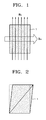
- FIGS. 1 through 3 are views for explaining a magnetostrictive effect used in an apparatus and method for generating and sensing torsional vibrations according to an embodiment of the present invention.
- the magnetostrictive body 1 when two perpendicular magnetic fields, i.e., a first magnetic field B s and a second magnetic field B D , are applied on a magnetostrictive body 1, the magnetostrictive body 1 may be deformed in a shear direction as shown in FIG. 2. That is, when the first magnetic field B s is kept constant, i.e., the intensity thereof is not changed, and the second dynamic magnetic field B D is changed, i.e., the intensity thereof is changed, the magnetostrictive body 1 is deformed according to the change of the second magnetic field B D , as shown in FIG. 2. That is, by changing the intensity and cycle of the second magnetic field B D , it is possible to control the deformation and cycle of the magnetostrictive body 1.
- FIG. 3 illustrates an instance of using such a magnetostrictive effect in the case of a bar member.
- a magnetostrictive body 1 When a magnetostrictive body 1 is wound around a bar member 2, if a static magnetic field B s is applied on the magnetostrictive body 1 and a dynamic magnetic field B D is applied in a longitudinal direction of the bar member 2, substantially perpendicular to the direction of the static magnetic field B s , the magnetostrictive body 1 is deformed.
- the magnetostrictive body 1 is tightly attached to the bar member 2 such that torsional vibrations may be generated in the bar member 2 according to the deformation of the magnetostrictive body 1.
- the frequency and intensity of the dynamic magnetic field B D it is possible to adjust the frequency and intensity of torsional vibrations generated in the bar member 2.
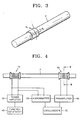
- FIG. 4 is a view a schematic view of an apparatus for generating and sensing torsional vibrations using magnetostriction according to an embodiment of the present invention
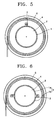
- FIG. 5 is a cross-sectional view taken along line V-V in FIG. 4.
- the apparatus for generating and sensing torsional vibrations includes a torsional vibration generating part 10 disposed at one side of a test part 2, and a torsional vibration sensing part 20 disposed at the other side of the test part 2.
- the torsional vibration generating part 10 and the torsional vibration sensing part 20 are spaced apart by a predetermined distance.
- the test part 2 may be any kind of mechanical part having an arbitrary cross-section and a predetermined length.
- each of the torsional vibration generating part 10 and the torsional vibration sensing part 20 includes a magnetostrictive body 1, a first magnetic field forming part, and a second magnetic field forming part.
- the magnetostrictive body 1 is attached around the test part 2 and may be formed of one member as shown in FIG. 5.
- the magnetostrictive body 1 may be formed of a magnetic material selected from the group consisting of a ferromagnetic material such as Fe, Ni, and Co, alloys thereof, and a material having a large deformability.
- the first magnetic field forming part forms a magnetic field around the test part 2 in a circumferential direction of the magnetostrictive body 1 and may be formed of a magnet 3 disposed in a circumferential direction of the magnetostrictive body 1, as shown in FIG. 5.
- the second magnetic field forming part forms a magnetic field in a longitudinal direction of the test part 2 and includes an insulating body 4 wound around the test part 2 and spaced apart therefrom by a predetermined gap, and a coil 6 wound around the insulating body 4, as shown in FIGS. 4 and 5.
- a function generator 40, a power amplifier 30, and an amperemeter 50 are connected to the coil 6 of the second magnetic field forming part.
- a pre-amplifier 60, an oscilloscope 70, and the amperemeter 50 are connected to the coil 6 installed at the second magnetic field forming part of the torsional vibration sensing part.
- the apparatus generates torsional vibrations and simultaneously senses the torsional vibrations as follows.
- the torsional vibration generating part 10 generates torsional vibrations on the test part 2 by changing the intensity of a magnetic field formed by the second magnetic field forming part without changing the intensity of a magnetic field formed by the first magnetic field forming part so that the magnetostrictive body 1 undergoes shear deformation with respect to a longitudinal direction of the test part 2, using a magnetostrictive phenomenon.
- the torsional vibration sensing part 20 measures torsional vibration characteristics of the test part 2 by sensing the variation in the intensity of a magnetic field around the magnetostrictive body 1 based on an inverse magnetostrictive phenomenon occurring from torsional vibrations generated by the torsional vibration generating part 10, when a magnetic field formed by the first magnetic field forming part is kept constant.
- the magnetostrictive body 1 and the first magnetic field forming part included in both the torsional vibration generating part 10 and the torsional vibration sensing part 20 may have various shapes and are not particularly limited to the shapes shown in FIG. 5.
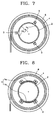
- FIGS. 6 through 10 are cross-sectional views of the magnetostrictive body 1 and the first magnetic field forming part employed in the apparatus for generating and sensing torsional vibrations according to other embodiments of the present invention.
- the magnetostrictive body 1 may be formed of two pieces, unlike the embodiment of FIG. 5. That is, the magnetostrictive body 1 may be formed of magnetostrictive pieces 1 a and 1 b having the same size or different sizes. Magnets 3 constituting the first magnetic field forming part may be disposed in every gap between the magnetostrictive pieces 1 a and 1 b, or in one or some of the gaps between the magnetostrictive pieces 1 a and 1 b.
- the magnetostrictive pieces 1 a and 1 b of equal sizes may be disposed at substantially equal intervals, and the magnets 3 may be disposed in every gap between the magnetostrictive pieces 1 a and 1 b.
- the number of magnetostrictive pieces 1 a and 1 b may be higher and the magnets 3 may be disposed in every gap therebetween such that the magnetic field is uniformly formed around the test part 2.
- the magnetostrictive body 1 may be formed of three pieces 1 a, 1 b and 1 c disposed at equal intervals from each other. Such an arrangement is particularly advantageous when the test part 2 has a larger diameter.
- the magnetostrictive pieces are attached to the test part using one adhesive material selected from the group consisting of epoxy, strong adhesive agents, and tapes.
- FIG. 8 illustrates an example when the magnets 3 are installed on a surface of the magnetostrictive body 1.
- the magnetostrictive body 1 has a predetermined number of magnetostrictive pieces 1a and 1 b, and the magnets 3 are respectively attached to opposite ends of the magnetostrictive pieces 1 a and 1 b.
- the magnets 3 are disposed to have different polarities on the opposite surfaces of the magnetostrictive pieces 1 a and 1 b. This creates magnetic fields passing through the magnetostrictive pieces 1 a and 1 b.
- the magnetic fields pass through the magnetostrictive body 1 having high magnetic permeability at the side that the magnets 3 remain in contact with the magnetostrictive body 1, but the magnetic fields pass through the air of low magnetic permeability at the opposite side, thus causing a relatively great deal of magnetic flux to be leaked.
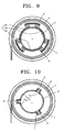
- FIG. 9 illustrates an example where magnetic flux leakage is reduced in comparison with the embodiment shown in FIG. 8.
- yokes 7 that interconnect those polarities opposite to the polarities of the magnets 3 in contact with the magnetostrictive pieces 1 a, 1 b and 1 c.
- the yokes may be formed of a material having higher magnetic permeability than air.
- FIG. 10 illustrates an example where magnets 3 and yokes 7 are arranged in the gaps between magnetostrictive pieces 1 a and 1 b.
- the magnets 3 are installed to form magnetic fields in a direction parallel to a tangential line of a cross-section of the test part 2 around the test part 2, and the yokes 7 are installed to interconnect the magnets 3 and the magnetostrictive pieces 1 a and 1 b.
- the magnets 3 are installed to contact the test part 2, like in the embodiment shown in FIG. 5 or 6.
- the yokes 7 formed of a material having high magnetic permeability are installed between the magnets 3 and the magnetostrictive body 1 so that they can contact the test part 2. The yokes 7 make it possible to reduce the magnetic flux leakage which would otherwise occur through air between the magnets 3 and the magnetostrictive body 1 as shown in the embodiment of FIGS. 5 through 7.
- FiG. 11 shows an example where magnets 3 are spaced apart from a test part 2 by yokes 7, unlike the embodiment shown in FIG. 10.
- the magnets 3 may be installed either in direct contact with the test part 2 as shown in FIGS. 5 through 7 and 10, or spaced apart from the test part 2 as shown in FIG 11.
- FIG. 12 illustrates an example where electromagnets 8 are employed instead of the permanent magnets 3 shown in FIG. 11, in order to form a magnetic field.
- a separate wire must be connected to each coil of the electromagnets for forming a first magnetic field.
- the use of the electromagnet 8 is advantageous in that the intensity of the first magnetic field formed by the electromagnet 8 can be changed to thereby create variable torsional vibrations in the torsional vibration generating part.
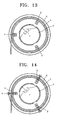
- FIG. 13 illustrates an example where magnets 3 are supported in direct contact with an insulating body 4.
- bonding means such as an adhesive agent, an adhesive tape, or the like may be used to support the magnets 3 on the insulating body 4.
- the magnets 3 can be mounted by attaching the magnetostrictive body 1 to the test part 2 and then installing the insulating body 4 that contains the magnets 3 therein. This removes the need to attach the magnets 3 to the test part 2 one by one.
- FIG. 14 illustrates an example where the magnets 3 are supported by the insulating body 4 through the use of position adjustment members 9
- FIG. 15 illustrates an example where the magnets 3 are supported by the insulating body 4 through the use of yokes 7 and position adjustment members 9 in case that the yokes 7 interconnect the magnets 3 as shown in FIG. 9.
- the position adjustment members 9 may be embodied in a variety of types, including a combination of bolts and nuts as shown in the drawings.
- modal testing may be performed in the following manner. After determining a vibration generating position and a vibration sensing position on the test part 2, magnetostrictive pieces are respectively installed at the two positions. Then, a first magnetic field is formed around the magnetostrictive pieces, and a second magnetic field is formed around the magnetostrictive body 1 in a direction substantially perpendicular to the first magnetic field. The first and second magnetic fields may be formed according to one of the embodiments described hereinbefore. Subsequently, the intensity of the second magnetic field formed around the magnetostrictive body 1 which is attached at the vibration generating position is changed to generate torsional vibrations on the test part 2.
- the vibrations thus generated serves to change the intensity of the second magnetic field by an inverse magnetostrictive effect that occurs around the magnetostrictive body 1 attached at the vibration sensing position.
- the change of the second magnetic field formed around the magnetostrictive body 1, which is attached at the vibration sensing position is sensed to measure torsional vibrations.
- the natural frequency and mode shape of the test part 2 can be determined.
- the first magnetic field may be formed without using the various kinds of magnetic field forming structures described hereinbefore.
- FIG. 16 is a cross-sectional view for explaining a method of forming a magnetic field around the test part 2 only when the modal testing is carried out.
- modal testing is performed after the magnets 3 are rubbed along the magnetostrictive body 1 for pre-magnetization, instead of fixedly installing a separate magnetic field forming part on the test part 2.
- magnetostrictive body having one, two, or three of magnetostrictive pieces and three or less magnets
- the number of magnetostrictive pieces and magnets is not particularly limited to the ones illustrated hereinbefore without departing from the scope of the present invention.
- the magnetostrictive body may be in the form of a thin strip shape as shown in the drawings, but is not limited thereto.
- Modal testing can be conducted on a part such as a pipe, a beam, a bar, a shaft, or the like, by using the apparatus and method for generating and sensing torsional vibrations in accordance with the present invention.
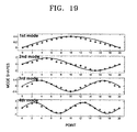
- FIGS. 17 through 19 illustrate graphs showing modal testing results obtained when testing a pipe using the apparatus and method for generating and sensing torsional vibrations in accordance with the present invention.
- the test pipe is made of aluminum and has an outer diameter of 25 mm, a thickness of 1.8 mm, and a length of 1 m. Both ends of the aluminum pipe are left free during modal testing.
- FIG. 17 shows torsional vibration signals obtained by using the apparatus and method for generating and sensing torsional vibrations of the present invention when testing the above pipe.
- FIG. 18 is a graph representing the frequency response function (log magnitude versus frequency) of the test pipe.
- the peak of the frequency response function corresponds to the natural frequency of the test pipe.
- FIG. 19 shows the theoretical (solid line) and experimental (circles) torsional vibration modes of the test pipe. After the natural frequency and the vibration modes of the pipe are obtained as shown in FIGS. 18 and 19, they are accounted for when designing the machine having the pipe as a part.
- the machine parts are designed such that the frequencies of vibrations generated when they are used for various operations avoid the natural frequencies of them.
- the machine parts are designed such that the frequencies of vibrations generated when they are used for various operations avoid the natural frequencies of them.
- it is possible to prevent the machine parts from breaking, which would otherwise take place when the vibration frequencies of the parts during operations of a machine are equal to the resonance frequencies.
- the present invention provides an apparatus and a method for stably generating torsional vibrations and sensing the torsional vibrations using magnetostrictive effect and inverse magnetostrictive effect when performing the modal testing of a machine part such as a pipe, a beam, a bar, a shaft, or the like.
- the apparatus and method according to the present invention can accurately and conveniently perform the modal testing of the machine part about torsional vibrations, and use the results of the testing in designing machines including the machine part. Accordingly, it is possible to manufacture machine parts with improved structural stability.
- torsional vibrations can be generated regardless of the intensity of a current applied to a coil, modal testing of a machine part can be performed with improved repeatability.
Landscapes
- Physics & Mathematics (AREA)
- General Physics & Mathematics (AREA)
- Engineering & Computer Science (AREA)
- Mechanical Engineering (AREA)
- Apparatuses For Generation Of Mechanical Vibrations (AREA)
- Investigating Strength Of Materials By Application Of Mechanical Stress (AREA)
- Investigating Or Analyzing Materials By The Use Of Magnetic Means (AREA)
- Measuring Magnetic Variables (AREA)
Applications Claiming Priority (1)
| Application Number | Priority Date | Filing Date | Title |
|---|---|---|---|
| KR1020050111033A KR100684691B1 (ko) | 2005-11-19 | 2005-11-19 | 자기 변형을 이용한 비틀림 진동 발생 및 측정 장치와 이를이용한 비틀림 진동 발생 및 측정 방법 |
Publications (1)
| Publication Number | Publication Date |
|---|---|
| EP1788366A2 true EP1788366A2 (de) | 2007-05-23 |
Family
ID=37845283
Family Applications (1)
| Application Number | Title | Priority Date | Filing Date |
|---|---|---|---|
| EP06252769A Withdrawn EP1788366A2 (de) | 2005-11-19 | 2006-05-26 | Vorrichtung und Verfahren zur Erzeugung und Wahrnehmung von Drehschwingungen mittels Magnetostriktion |
Country Status (4)
| Country | Link |
|---|---|
| US (1) | US7621189B2 (de) |
| EP (1) | EP1788366A2 (de) |
| JP (1) | JP4182121B2 (de) |
| KR (1) | KR100684691B1 (de) |
Cited By (1)
| Publication number | Priority date | Publication date | Assignee | Title |
|---|---|---|---|---|
| CN105397567A (zh) * | 2015-12-23 | 2016-03-16 | 王晶怡 | 一种精密加工中的低功耗精度在线监测系统 |
Families Citing this family (12)
| Publication number | Priority date | Publication date | Assignee | Title |
|---|---|---|---|---|
| KR101073686B1 (ko) * | 2009-04-08 | 2011-10-14 | 서울대학교산학협력단 | 분절형 자기변형 패치 배열 트랜스듀서, 이를 구비한 구조 진단 장치 및 이 트랜스듀서의 작동 방법 |
| KR101061590B1 (ko) * | 2009-06-23 | 2011-09-02 | 서울대학교산학협력단 | 자기 변형 트랜스듀서, 이를 이용한 구조 진단 장치 및 구조 진단 방법 |
| FR2963428B1 (fr) * | 2010-07-27 | 2017-01-06 | Ass Inst De Soudure | Procede de preparation d'une piece pour lui conferer localement des proprietes magnetostrictives |
| FR2963427B1 (fr) * | 2010-07-27 | 2013-04-05 | Ass Inst De Soudure | Procede de preparation d'une piece basee sur la projection d'un materiau magnetostrictif |
| WO2012013900A1 (fr) * | 2010-07-27 | 2012-02-02 | Association Institut De Soudure | Procede de preparation d'une piece basee sur la formation a sa surface d'un materiau magnetostrictif |
| FR2963429B1 (fr) * | 2010-07-27 | 2021-09-24 | Association Inst De Soudure | Procede de preparation d'une piece basee sur la realisation d'une soudure ou brasure avec un materiau magnetostrictif |
| KR101082327B1 (ko) * | 2011-02-07 | 2011-11-10 | 한국생산기술연구원 | 토크센서 테스트 장치 |
| CA2943976A1 (en) * | 2014-03-26 | 2015-10-01 | Methode Electronics, Inc. | Systems and methods for reducing rotation noise in a magnetoelastic device and measuring torque, speed, and orientation |
| US10254181B2 (en) * | 2014-03-26 | 2019-04-09 | Methode Electronics, Inc. | Systems and methods for reducing rotation noise in a magnetoelastic device and measuring torque, speed, and orientation |
| RU2615915C1 (ru) * | 2016-03-30 | 2017-04-11 | Федеральное государственное бюджетное образовательное учреждение высшего образования "Владимирский Государственный Университет имени Александра Григорьевича и Николая Григорьевича Столетовых" (ВлГУ) | Датчик крутильных колебаний |
| CN107422027B (zh) * | 2017-09-05 | 2020-09-25 | 北京工业大学 | 基于双环永磁体阵列的扭转模态导波磁致伸缩传感器 |
| US11041769B2 (en) * | 2019-07-15 | 2021-06-22 | Baker Hughes Oilfield Operations, Llc | Field calibration for torsional vibration sensor |
Family Cites Families (18)
| Publication number | Priority date | Publication date | Assignee | Title |
|---|---|---|---|---|
| US2806533A (en) * | 1949-11-10 | 1957-09-17 | Union Oil Co | Vibrational wave generator |
| US2876419A (en) * | 1954-12-01 | 1959-03-03 | Bell Telephone Labor Inc | Magnetostriction devices |
| US3173131A (en) * | 1958-03-19 | 1965-03-09 | Bell Telephone Labor Inc | Magneostrictive apparatus |
| US3697867A (en) * | 1969-06-19 | 1972-10-10 | Cavitron Corp | Vibration sensor utilizing eddy currents induced in member vibrating in the field of a magnet |
| BE786393A (fr) * | 1971-07-19 | 1973-01-18 | Caterpillar Tractor Co | Machine pour eprouver des amortisseurs de |
| US4439730A (en) * | 1981-05-08 | 1984-03-27 | Amf Inc. | Nondestructive inspection apparatus and method utilizing combined inspection signals obtained from orthogonal magnetic fields |
| JPS60118730U (ja) | 1984-01-20 | 1985-08-10 | 三菱重工業株式会社 | 捩り振動計測装置 |
| JPH0672825B2 (ja) * | 1984-08-30 | 1994-09-14 | 株式会社豊田中央研究所 | トルク測定装置 |
| US4823620A (en) * | 1986-02-10 | 1989-04-25 | Nissan Motor Company, Ltd. | Magnetostrictive device for measuring torsional torque |
| US4896544A (en) * | 1986-12-05 | 1990-01-30 | Mag Dev Inc. | Magnetoelastic torque transducer |
| JPS6483951A (en) * | 1987-09-25 | 1989-03-29 | Toshiba Corp | Torsional vibration damping device |
| JPH01187424A (ja) * | 1988-01-22 | 1989-07-26 | Toshiba Corp | トルクセンサ |
| JPH06307919A (ja) * | 1993-04-21 | 1994-11-04 | Toshiba Eng Co Ltd | 回転部振れ測定装置 |
| US7131339B2 (en) | 1997-01-27 | 2006-11-07 | Southwest Research Institute | Measurement of torsional dynamics of rotating shafts using magnetostrictive sensors |
| KR100500560B1 (ko) * | 1997-03-28 | 2005-07-12 | 만네스만 파우데오 아게 | 자기탄성 트랜스듀서 제조 방법 |
| US6429650B1 (en) | 1999-03-17 | 2002-08-06 | Southwest Research Institute | Method and apparatus generating and detecting torsional wave inspection of pipes or tubes |
| US6467360B1 (en) * | 1999-04-23 | 2002-10-22 | Trw Inc. | Torque sensing apparatus and method |
| KR100482103B1 (ko) * | 2002-08-13 | 2005-04-13 | 현대자동차주식회사 | 자동차의 축 굽힘진동 측정장치 |
-
2005
- 2005-11-19 KR KR1020050111033A patent/KR100684691B1/ko not_active Expired - Fee Related
-
2006
- 2006-05-26 EP EP06252769A patent/EP1788366A2/de not_active Withdrawn
- 2006-05-31 US US11/443,196 patent/US7621189B2/en active Active
- 2006-06-06 JP JP2006157150A patent/JP4182121B2/ja not_active Expired - Fee Related
Cited By (1)
| Publication number | Priority date | Publication date | Assignee | Title |
|---|---|---|---|---|
| CN105397567A (zh) * | 2015-12-23 | 2016-03-16 | 王晶怡 | 一种精密加工中的低功耗精度在线监测系统 |
Also Published As
| Publication number | Publication date |
|---|---|
| KR100684691B1 (ko) | 2007-02-22 |
| JP4182121B2 (ja) | 2008-11-19 |
| US20070113684A1 (en) | 2007-05-24 |
| JP2007139745A (ja) | 2007-06-07 |
| US7621189B2 (en) | 2009-11-24 |
Similar Documents
| Publication | Publication Date | Title |
|---|---|---|
| US8354842B2 (en) | Segmented magnetostrictive patch array transducer, apparatus for diagnosing structural fault by using the same, and method of operating the same | |
| US7215118B2 (en) | Transducer for generating and measuring torsional waves, and apparatus and method for structural diagnosis using the same | |
| US7621189B2 (en) | Apparatus and method for generating and sensing torsional vibrations using magnetostriction | |
| US8356519B2 (en) | Non-contact type transducer for rod member having multi-loop coil | |
| US5895856A (en) | Electromagnetic acoustic transducer and methods of determining physical properties of cylindrical bodies using an electromagnetic acoustic transducer | |
| US20120296577A1 (en) | Magnetoelastic force sensors, transducers, methods, and systems for assessing bending stress | |
| KR100561215B1 (ko) | 탄성 초음파를 발생 및 측정할 수 있는 자기변형트랜스듀서와 이를 이용한 구조진단 장치 | |
| JP2009506334A (ja) | センサデバイス、センサ装置、および対象物の特性を測定する方法 | |
| Kim et al. | Application of magnetomechanical sensors for modal testing | |
| KR0170544B1 (ko) | 비파괴 검사 장치 | |
| JP4605307B1 (ja) | ボルト締付力検査装置 | |
| US20110031966A1 (en) | Non-contact type transducer having multi-loop coil for plate member | |
| Kim et al. | A novel Terfenol-D transducer for guided-wave inspection of a rotating shaft | |
| US6119522A (en) | Electromagnetic acoustic transducer and methods of determining physical properties of cylindrical bodies using an electromagnetic acoustic transducer | |
| Dapino et al. | Measured Terfenol-D material properties under varied applied magnetic field levels | |
| KR100573735B1 (ko) | 비자성체 배관의 비접촉식 굽힘 진동 발생 및 측정 장치 | |
| JP4203045B2 (ja) | テールパッチを利用した磁気変形トランスデューサと、それを利用した弾性波測定装置 | |
| KR101046539B1 (ko) | 센서 | |
| US20060210100A1 (en) | Electromagnetic acoustic transducer for generating and measuring bending vibration in rod member using anti-symmetric magnetic field structure | |
| JP2004219105A (ja) | ひずみセンサおよびひずみ計測方法 | |
| RU2781466C1 (ru) | Установка для испытания образцов на усталость | |
| Han et al. | Magnetostrictive sensor applications for the modal testing of insulated pipe | |
| Park et al. | Torsional wave transduction using obliquely-bonded magnetostrictive nickel strips in cylinders | |
| Yoo et al. | External Loading Effects on Guided Wave Magnetostrictive Sensor Using a Surface-Bonded Nickel Patch | |
| JPH02310438A (ja) | トルク伝達状況監視方法 |
Legal Events
| Date | Code | Title | Description |
|---|---|---|---|
| PUAI | Public reference made under article 153(3) epc to a published international application that has entered the european phase |
Free format text: ORIGINAL CODE: 0009012 |
|
| 17P | Request for examination filed |
Effective date: 20060626 |
|
| AK | Designated contracting states |
Kind code of ref document: A2 Designated state(s): AT BE BG CH CY CZ DE DK EE ES FI FR GB GR HU IE IS IT LI LT LU LV MC NL PL PT RO SE SI SK TR |
|
| AX | Request for extension of the european patent |
Extension state: AL BA HR MK YU |
|
| STAA | Information on the status of an ep patent application or granted ep patent |
Free format text: STATUS: THE APPLICATION IS DEEMED TO BE WITHDRAWN |
|
| 18D | Application deemed to be withdrawn |
Effective date: 20121201 |