EP1788342A1 - Verfahren zur Herstellung eines Mantelpenetrators - Google Patents
Verfahren zur Herstellung eines Mantelpenetrators Download PDFInfo
- Publication number
- EP1788342A1 EP1788342A1 EP05077635A EP05077635A EP1788342A1 EP 1788342 A1 EP1788342 A1 EP 1788342A1 EP 05077635 A EP05077635 A EP 05077635A EP 05077635 A EP05077635 A EP 05077635A EP 1788342 A1 EP1788342 A1 EP 1788342A1
- Authority
- EP
- European Patent Office
- Prior art keywords
- jacket
- penetrator
- rod
- core
- tube
- Prior art date
- Legal status (The legal status is an assumption and is not a legal conclusion. Google has not performed a legal analysis and makes no representation as to the accuracy of the status listed.)
- Withdrawn
Links
- 238000000034 method Methods 0.000 title claims abstract description 33
- 238000004519 manufacturing process Methods 0.000 title claims abstract description 9
- WFKWXMTUELFFGS-UHFFFAOYSA-N tungsten Chemical compound [W] WFKWXMTUELFFGS-UHFFFAOYSA-N 0.000 claims abstract description 10
- 229910052721 tungsten Inorganic materials 0.000 claims abstract description 10
- 239000010937 tungsten Substances 0.000 claims abstract description 10
- 238000003466 welding Methods 0.000 claims abstract description 9
- JFALSRSLKYAFGM-UHFFFAOYSA-N uranium(0) Chemical group [U] JFALSRSLKYAFGM-UHFFFAOYSA-N 0.000 claims abstract description 6
- 229910001080 W alloy Inorganic materials 0.000 claims abstract 2
- 239000002360 explosive Substances 0.000 claims description 24
- 238000010438 heat treatment Methods 0.000 claims description 4
- 229910052751 metal Inorganic materials 0.000 description 21
- 239000002184 metal Substances 0.000 description 21
- 229910045601 alloy Inorganic materials 0.000 description 14
- 239000000956 alloy Substances 0.000 description 14
- 239000000463 material Substances 0.000 description 14
- 229910000831 Steel Inorganic materials 0.000 description 8
- 150000002739 metals Chemical class 0.000 description 8
- 239000010959 steel Substances 0.000 description 8
- 238000005253 cladding Methods 0.000 description 6
- 229910001385 heavy metal Inorganic materials 0.000 description 6
- 238000005452 bending Methods 0.000 description 5
- 230000035515 penetration Effects 0.000 description 5
- 229910001240 Maraging steel Inorganic materials 0.000 description 3
- 230000001133 acceleration Effects 0.000 description 3
- 238000007596 consolidation process Methods 0.000 description 3
- 238000005474 detonation Methods 0.000 description 3
- 239000000843 powder Substances 0.000 description 3
- 239000013077 target material Substances 0.000 description 3
- XEEYBQQBJWHFJM-UHFFFAOYSA-N Iron Chemical compound [Fe] XEEYBQQBJWHFJM-UHFFFAOYSA-N 0.000 description 2
- PXHVJJICTQNCMI-UHFFFAOYSA-N Nickel Chemical compound [Ni] PXHVJJICTQNCMI-UHFFFAOYSA-N 0.000 description 2
- 239000000654 additive Substances 0.000 description 2
- 230000000996 additive effect Effects 0.000 description 2
- 238000005275 alloying Methods 0.000 description 2
- 229910001092 metal group alloy Inorganic materials 0.000 description 2
- 238000012546 transfer Methods 0.000 description 2
- PAWQVTBBRAZDMG-UHFFFAOYSA-N 2-(3-bromo-2-fluorophenyl)acetic acid Chemical compound OC(=O)CC1=CC=CC(Br)=C1F PAWQVTBBRAZDMG-UHFFFAOYSA-N 0.000 description 1
- 229910000838 Al alloy Inorganic materials 0.000 description 1
- 229910000975 Carbon steel Inorganic materials 0.000 description 1
- 229910001209 Low-carbon steel Inorganic materials 0.000 description 1
- 229910000990 Ni alloy Inorganic materials 0.000 description 1
- 229910001069 Ti alloy Inorganic materials 0.000 description 1
- 238000004026 adhesive bonding Methods 0.000 description 1
- 229910052782 aluminium Inorganic materials 0.000 description 1
- XAGFODPZIPBFFR-UHFFFAOYSA-N aluminium Chemical compound [Al] XAGFODPZIPBFFR-UHFFFAOYSA-N 0.000 description 1
- 238000005219 brazing Methods 0.000 description 1
- 239000010962 carbon steel Substances 0.000 description 1
- 239000010941 cobalt Substances 0.000 description 1
- 229910017052 cobalt Inorganic materials 0.000 description 1
- GUTLYIVDDKVIGB-UHFFFAOYSA-N cobalt atom Chemical compound [Co] GUTLYIVDDKVIGB-UHFFFAOYSA-N 0.000 description 1
- 239000013078 crystal Substances 0.000 description 1
- 230000002542 deteriorative effect Effects 0.000 description 1
- 230000001627 detrimental effect Effects 0.000 description 1
- 230000000694 effects Effects 0.000 description 1
- 230000003628 erosive effect Effects 0.000 description 1
- 239000003721 gunpowder Substances 0.000 description 1
- 230000003116 impacting effect Effects 0.000 description 1
- 238000011835 investigation Methods 0.000 description 1
- 238000005342 ion exchange Methods 0.000 description 1
- 229910052742 iron Inorganic materials 0.000 description 1
- 239000005300 metallic glass Substances 0.000 description 1
- 238000000386 microscopy Methods 0.000 description 1
- 239000000203 mixture Substances 0.000 description 1
- 229910052759 nickel Inorganic materials 0.000 description 1
- 238000009304 pastoral farming Methods 0.000 description 1
- 230000000149 penetrating effect Effects 0.000 description 1
- 229920000642 polymer Polymers 0.000 description 1
- 238000012545 processing Methods 0.000 description 1
- 239000003380 propellant Substances 0.000 description 1
- 239000007787 solid Substances 0.000 description 1
- 239000007858 starting material Substances 0.000 description 1
- 238000005728 strengthening Methods 0.000 description 1
- 239000002023 wood Substances 0.000 description 1
Images
Classifications
-
- F—MECHANICAL ENGINEERING; LIGHTING; HEATING; WEAPONS; BLASTING
- F42—AMMUNITION; BLASTING
- F42B—EXPLOSIVE CHARGES, e.g. FOR BLASTING, FIREWORKS, AMMUNITION
- F42B12/00—Projectiles, missiles or mines characterised by the warhead, the intended effect, or the material
- F42B12/02—Projectiles, missiles or mines characterised by the warhead, the intended effect, or the material characterised by the warhead or the intended effect
- F42B12/04—Projectiles, missiles or mines characterised by the warhead, the intended effect, or the material characterised by the warhead or the intended effect of armour-piercing type
- F42B12/06—Projectiles, missiles or mines characterised by the warhead, the intended effect, or the material characterised by the warhead or the intended effect of armour-piercing type with hard or heavy core; Kinetic energy penetrators
-
- B—PERFORMING OPERATIONS; TRANSPORTING
- B23—MACHINE TOOLS; METAL-WORKING NOT OTHERWISE PROVIDED FOR
- B23K—SOLDERING OR UNSOLDERING; WELDING; CLADDING OR PLATING BY SOLDERING OR WELDING; CUTTING BY APPLYING HEAT LOCALLY, e.g. FLAME CUTTING; WORKING BY LASER BEAM
- B23K20/00—Non-electric welding by applying impact or other pressure, with or without the application of heat, e.g. cladding or plating
- B23K20/06—Non-electric welding by applying impact or other pressure, with or without the application of heat, e.g. cladding or plating by means of high energy impulses, e.g. magnetic energy
- B23K20/08—Explosive welding
-
- B—PERFORMING OPERATIONS; TRANSPORTING
- B23—MACHINE TOOLS; METAL-WORKING NOT OTHERWISE PROVIDED FOR
- B23K—SOLDERING OR UNSOLDERING; WELDING; CLADDING OR PLATING BY SOLDERING OR WELDING; CUTTING BY APPLYING HEAT LOCALLY, e.g. FLAME CUTTING; WORKING BY LASER BEAM
- B23K20/00—Non-electric welding by applying impact or other pressure, with or without the application of heat, e.g. cladding or plating
- B23K20/22—Non-electric welding by applying impact or other pressure, with or without the application of heat, e.g. cladding or plating taking account of the properties of the materials to be welded
- B23K20/233—Non-electric welding by applying impact or other pressure, with or without the application of heat, e.g. cladding or plating taking account of the properties of the materials to be welded without ferrous layer
-
- F—MECHANICAL ENGINEERING; LIGHTING; HEATING; WEAPONS; BLASTING
- F42—AMMUNITION; BLASTING
- F42B—EXPLOSIVE CHARGES, e.g. FOR BLASTING, FIREWORKS, AMMUNITION
- F42B12/00—Projectiles, missiles or mines characterised by the warhead, the intended effect, or the material
- F42B12/72—Projectiles, missiles or mines characterised by the warhead, the intended effect, or the material characterised by the material
- F42B12/74—Projectiles, missiles or mines characterised by the warhead, the intended effect, or the material characterised by the material of the core or solid body
-
- F—MECHANICAL ENGINEERING; LIGHTING; HEATING; WEAPONS; BLASTING
- F42—AMMUNITION; BLASTING
- F42B—EXPLOSIVE CHARGES, e.g. FOR BLASTING, FIREWORKS, AMMUNITION
- F42B12/00—Projectiles, missiles or mines characterised by the warhead, the intended effect, or the material
- F42B12/72—Projectiles, missiles or mines characterised by the warhead, the intended effect, or the material characterised by the material
- F42B12/76—Projectiles, missiles or mines characterised by the warhead, the intended effect, or the material characterised by the material of the casing
-
- B—PERFORMING OPERATIONS; TRANSPORTING
- B23—MACHINE TOOLS; METAL-WORKING NOT OTHERWISE PROVIDED FOR
- B23K—SOLDERING OR UNSOLDERING; WELDING; CLADDING OR PLATING BY SOLDERING OR WELDING; CUTTING BY APPLYING HEAT LOCALLY, e.g. FLAME CUTTING; WORKING BY LASER BEAM
- B23K2103/00—Materials to be soldered, welded or cut
- B23K2103/08—Non-ferrous metals or alloys
- B23K2103/10—Aluminium or alloys thereof
-
- B—PERFORMING OPERATIONS; TRANSPORTING
- B23—MACHINE TOOLS; METAL-WORKING NOT OTHERWISE PROVIDED FOR
- B23K—SOLDERING OR UNSOLDERING; WELDING; CLADDING OR PLATING BY SOLDERING OR WELDING; CUTTING BY APPLYING HEAT LOCALLY, e.g. FLAME CUTTING; WORKING BY LASER BEAM
- B23K2103/00—Materials to be soldered, welded or cut
- B23K2103/08—Non-ferrous metals or alloys
- B23K2103/14—Titanium or alloys thereof
-
- B—PERFORMING OPERATIONS; TRANSPORTING
- B23—MACHINE TOOLS; METAL-WORKING NOT OTHERWISE PROVIDED FOR
- B23K—SOLDERING OR UNSOLDERING; WELDING; CLADDING OR PLATING BY SOLDERING OR WELDING; CUTTING BY APPLYING HEAT LOCALLY, e.g. FLAME CUTTING; WORKING BY LASER BEAM
- B23K2103/00—Materials to be soldered, welded or cut
- B23K2103/18—Dissimilar materials
- B23K2103/26—Alloys of Nickel and Cobalt and Chromium
Definitions
- the present invention is directed to a process for the production of a jacketed penetrator having a tungsten, tungsten heavy alloy (WHA) or depleted uranium core and a metallic jacket.
- WHA tungsten heavy alloy
- Kinetic energy ammunition is used to defeat armour. It consists of a long rod of a heavy metal that is accelerated to a velocity between 1200 and 2500 m/s.
- a sabot is used to transfer the pressure of the propellant to the accelerating long rod.
- the sabot separates from the long rod that flies independently to the target. Due to the high mass and velocity (hence kinetic energy) of the rod, upon impact with an armour material a very high pressure arises at the penetrator-target interface. This pressure will be much higher then the dynamic yield strength of the metals involved. Therefore, the target material or both metals will start to flow and a crater is formed in the target material. This penetration process continues as long as the velocity of the penetrator is high enough (the stagnation pressure remains above the dynamic yield strength of the target material) and it remains a penetrating length.
- Jacketed penetrators have been used long before, mainly due to the low strength and brittleness of the first generations of tungsten heavy alloys (WHA).
- WHA tungsten heavy alloys
- the WHA rod had to be sheated by a tube of a metal alloy that was strong enough. Later, the strength of the WHA was increased to an acceptable level and a jacket material was no longer necessary. The mass of the jacket also has to be accelerated and it was thought that a jacket even was detrimental to the penetration capabilities of the WHA long rod penetrator.
- US-A 2004/0158969 described one of these processes, namely heating the jacket to such a temperature that the inside diameter is sufficiently increased that the core can be placed inside it. After that, the combination is cooled down and an interference shrink-fit is obtained.
- the process of the invention is accordingly characterised by placing the core inside the jacket and explosively cladding the jacket on the core.
- a penetrator may be produced having superior properties in terms of mechanical properties, interface (shear) strength and a practically free choice in metal (alloy) type of the jacket material as well as its wall thickness.
- the process of this invention makes use of a tube material that can be obtained with the optimal wall thickness, alloy composition, as well as microstructure and heat treated condition for its optimal functioning as jacket. It is non-porous and normally less expensive compared to the same alloy mass in powder.
- Explosive cladding is usually done with ammonium-nitrate based explosives, but other explosives could suitably be used such as ion exchange explosives or diluted high explosives.
- a jacketed penetrator can be machined that has the required bonding strength and properties for optimal functioning.
- Explosive cladding is a one-step process that is of short duration and it can be applied on a very wide range of dissimilar metal alloy combinations. Furthermore, as a solid state room temperature process, it does not change the microstructure of the metals involved. Hence, the (optimal) mechanical properties provided by the alloy manufacturer are maintained.
- Explosive bonds have proven to be able to provide very high quality bonds that have a high (shear) strength and ductility. Both are essential for an optimal penetration performance during armour impact.
- the material of the tube may be selected from conventional steel materials (such as unalloyed carbon steel, mild steel, high strength steel, maraging steel), titanium-alloys, aluminum-alloys, nickel-alloys, berylium alloys, etc.
- the rod or core is produced from heavy metal or heavy metal alloys.
- tungsten tungsten heavy alloys (WHA) or depleted uranium are used, with a polycrystalline, single crystal, amorphous (metallic glass) or nano-structured microstructure. Alloying metals for the tungsten may be iron, nickel, cobalt. Amounts of alloying metal in the WHA are present in amounts of less than 20 wt.%.
- the penetrator has length which is preferably in excess of 20 cm, and may easily be made of a length up to 1 m or more.
- the core has preferably an L/D ration in excess of 30. In general this may be even more with penetrators that have length in excess of 20 cm, as the core will in general not be much thinner than 6 mm in diameter.
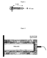
- the tube that is to be clad onto the core (rod) should have a larger inner diameter then the diameter of the rod. By centering the tube around the rod, a constant gap (stand-off) is created. Both metals may be glued to a temporary base plate (steel or wood) in order to fix their position. A second (cardboard or polymer) tube, that is longer and thicker then the metal tube, can be used to hold the explosive layer. This tube is also centered axisymmetrically which results in a constant layer thickness of the explosive mass.
- a detonator is placed on the explosive at the axis of symmetry.
- the metal tube Upon detonation of the explosive, the metal tube will be accelerated radially towards the rod. The impact between the flyer tube and rod will lead to a metallurgical bond between the two. At the end of the impact process the rod is clad with the metallic flyer tube. (See figure 2)
- the penetrator may be subjected to a heat treatment.
- a heat treatment at a temperature which is preferably between 250 and 750 °C and a period of time of not less than one hour, the remaining strain between the penetrator and the jacket material are substantially reduced.
- this same heat treatment (3 hours in air) will increase the strength of the maraging steel significantly (up to 2000 MPa).
- the gap between the starting materials may be vacumized in order to prevent the deteriorating action of the air being pushed out from between the two impacting surfaces.
- the gap (stand-off) between the metals is an important process parameter and will be determined experimentally depending on the size of the final penetrator (L/D) and the nature of the materials to be used. Furthermore, any free metal edges (tube openings) experience another acceleration from the detonating explosive compared to the metal situated further away from free edges. This results in an unbonded area of the free metal edges (about 5 to 10 times the metal thickness involved).
- centering pins In order to position the rod axi-symmetricaly inside the tube (jacket) during the explosive cladding process, i.e. that the gap is constant and the WHA rod is fully clad, use is preferably made of specially designed centering pins. These pins can be made out of any metal (steel, aluminum, etc.) and should be machined to have one end fit tightly into the flyer tube and the other end with the diameter equal to that of the rod. In order to facilitate the axial bonding between the pins (one on each side of the rod) and the rod, a small hole is drilled in the centerline of the edges of the rod. The pin has a corresponding part sticking out (as shown in figure 1). The pins are glued to the rod edges. The centering pins are made wider on the second end in order to get a close fit inside the ends of the tube (jacket material). In order to facilitate for the centering pins, the length of the tube is somewhat longer then the length of the rod to be clad.
- the rods are clad optimally and over the complete rod length.
- the clad rods are machined to the required form and dimensions for their function as jacketed penetrator. Sometimes the clad rods need to be straightened or heat treated before being machined.
- a WHA-rod with a length of 240 mm and a diameter of 6 mm (L/D 40) was surrounded by an unalloyed C-steel tube with an inner diameter of 9 mm and a wall thickness of 2 mm. Therefore, initially a constant gap of 1.5 mm existed between the two metal surfaces to be bonded.
- An explosive layer with constant layer thickness and density was applied around the C-steel tube and detonated inside an explosive chamber. The high pressure generated by the grazing detonation process accelerates the tube wall radially towards the WHA-rod. With the right parameters (mainly detonation velocity, mass ratio between the explosive and the tube and gap) the resulting inclined impact between the imploding tube surface on the rod results in a high quality explosive bond.
- the wall thickness of the steel tube has increased somewhat due to the implosion process.
- the clad rod is straightened and machined to the required final dimensions to be used as jacketed penetrator ammunition. Microscopy and ultrasonic investigation of the clad rod produced in this way demonstrated that no porosity or change in microstructure had occurred in both metals. A small increase in hardness was observed locally at the metal interface.
- the interface (shear) strength was statically measured to be above 300 MPa.
Landscapes
- Engineering & Computer Science (AREA)
- Chemical & Material Sciences (AREA)
- Combustion & Propulsion (AREA)
- General Engineering & Computer Science (AREA)
- Physics & Mathematics (AREA)
- Thermal Sciences (AREA)
- Mechanical Engineering (AREA)
- Pressure Welding/Diffusion-Bonding (AREA)
Priority Applications (5)
| Application Number | Priority Date | Filing Date | Title |
|---|---|---|---|
| EP05077635A EP1788342A1 (de) | 2005-11-21 | 2005-11-21 | Verfahren zur Herstellung eines Mantelpenetrators |
| PCT/NL2006/000587 WO2007058531A1 (en) | 2005-11-21 | 2006-11-21 | Process for the production of a jacketed penetrator |
| US12/094,353 US20080314233A1 (en) | 2005-11-21 | 2006-11-21 | Process for the Production of a Jacketed Penetrator |
| EP06835635A EP1957933A1 (de) | 2005-11-21 | 2006-11-21 | Verfahren zur herstellung eines mantelpenetrators |
| IL191577A IL191577A0 (en) | 2005-11-21 | 2008-05-20 | Process for the production of a jacketed penetrator |
Applications Claiming Priority (1)
| Application Number | Priority Date | Filing Date | Title |
|---|---|---|---|
| EP05077635A EP1788342A1 (de) | 2005-11-21 | 2005-11-21 | Verfahren zur Herstellung eines Mantelpenetrators |
Publications (1)
| Publication Number | Publication Date |
|---|---|
| EP1788342A1 true EP1788342A1 (de) | 2007-05-23 |
Family
ID=36101468
Family Applications (2)
| Application Number | Title | Priority Date | Filing Date |
|---|---|---|---|
| EP05077635A Withdrawn EP1788342A1 (de) | 2005-11-21 | 2005-11-21 | Verfahren zur Herstellung eines Mantelpenetrators |
| EP06835635A Withdrawn EP1957933A1 (de) | 2005-11-21 | 2006-11-21 | Verfahren zur herstellung eines mantelpenetrators |
Family Applications After (1)
| Application Number | Title | Priority Date | Filing Date |
|---|---|---|---|
| EP06835635A Withdrawn EP1957933A1 (de) | 2005-11-21 | 2006-11-21 | Verfahren zur herstellung eines mantelpenetrators |
Country Status (4)
| Country | Link |
|---|---|
| US (1) | US20080314233A1 (de) |
| EP (2) | EP1788342A1 (de) |
| IL (1) | IL191577A0 (de) |
| WO (1) | WO2007058531A1 (de) |
Families Citing this family (1)
| Publication number | Priority date | Publication date | Assignee | Title |
|---|---|---|---|---|
| GB201515386D0 (en) * | 2015-08-28 | 2015-10-14 | Materials Solutions Ltd | Additive manufacturing |
Citations (4)
| Publication number | Priority date | Publication date | Assignee | Title |
|---|---|---|---|---|
| FR2202275A1 (en) * | 1972-10-04 | 1974-05-03 | Dynamit Nobel Ag | Armour piercing shot - with core of high density sintered powder produced by explosive forming |
| DE3835808A1 (de) * | 1988-10-21 | 1990-04-26 | Rheinmetall Gmbh | Verfahren zur herstellung von hartkerngeschossen |
| DE19619192A1 (de) * | 1996-05-11 | 1997-11-13 | Diehl Gmbh & Co | Verfahren zur Herstellung eines Wickelpenetrators |
| FR2865536A1 (fr) * | 1988-03-02 | 2005-07-29 | Battelle Institut E V | Projectile |
Family Cites Families (6)
| Publication number | Priority date | Publication date | Assignee | Title |
|---|---|---|---|---|
| DE3030072A1 (de) * | 1980-08-09 | 1986-06-26 | Rheinmetall GmbH, 4000 Düsseldorf | Formschlussmittel, werkstoff zum bilden derselben und verfahren zum anordnen der formschlussmittel im umfangbereich eines fluggeschosses aus einer schwermetall-sinterlegierung |
| FI65177C (fi) * | 1981-05-07 | 1984-04-10 | Finnish Chemicals Oy | Saett att foga aluminium till titan genom svetsning och en svetsprodukt aostadkommen haerigenom |
| ES2038300T3 (es) * | 1987-09-18 | 1993-07-16 | Imperial Chemical Industries Plc | Union conjunta de componentes metalicos. |
| DE10238840A1 (de) * | 2002-08-23 | 2004-03-04 | Thomas Magnete Gmbh | Magnetanordnung |
| FR2854687B1 (fr) * | 2003-05-09 | 2006-06-16 | Giat Ind Sa | Projectile sous-calibre, barreau et sabot constituant un tel projectile |
| US7380504B2 (en) * | 2005-08-16 | 2008-06-03 | Raytheon Company | Telescoped projectile |
-
2005
- 2005-11-21 EP EP05077635A patent/EP1788342A1/de not_active Withdrawn
-
2006
- 2006-11-21 US US12/094,353 patent/US20080314233A1/en not_active Abandoned
- 2006-11-21 EP EP06835635A patent/EP1957933A1/de not_active Withdrawn
- 2006-11-21 WO PCT/NL2006/000587 patent/WO2007058531A1/en active Application Filing
-
2008
- 2008-05-20 IL IL191577A patent/IL191577A0/en unknown
Patent Citations (4)
| Publication number | Priority date | Publication date | Assignee | Title |
|---|---|---|---|---|
| FR2202275A1 (en) * | 1972-10-04 | 1974-05-03 | Dynamit Nobel Ag | Armour piercing shot - with core of high density sintered powder produced by explosive forming |
| FR2865536A1 (fr) * | 1988-03-02 | 2005-07-29 | Battelle Institut E V | Projectile |
| DE3835808A1 (de) * | 1988-10-21 | 1990-04-26 | Rheinmetall Gmbh | Verfahren zur herstellung von hartkerngeschossen |
| DE19619192A1 (de) * | 1996-05-11 | 1997-11-13 | Diehl Gmbh & Co | Verfahren zur Herstellung eines Wickelpenetrators |
Also Published As
| Publication number | Publication date |
|---|---|
| US20080314233A1 (en) | 2008-12-25 |
| EP1957933A1 (de) | 2008-08-20 |
| IL191577A0 (en) | 2008-12-29 |
| WO2007058531A1 (en) | 2007-05-24 |
Similar Documents
| Publication | Publication Date | Title |
|---|---|---|
| US7360488B2 (en) | Single phase tungsten alloy | |
| EP1299687B1 (de) | Bleifreie einlagezusammensetzung für hohlladungen | |
| US5279228A (en) | Shaped charge perforator | |
| US20090078144A1 (en) | Liner for shaped charges | |
| US7011027B2 (en) | Coated metal particles to enhance oil field shaped charge performance | |
| NO332903B1 (no) | Perforator, perforeringskanon, fremgangsmåte samt anvendelse | |
| EP0013367A1 (de) | Panzerdurchbrechendes Geschoss | |
| KR102203134B1 (ko) | 연성 외장에 의해 둘러싸인 코어를 포함하는 관통자 및 그 관통자의 제조방법 | |
| US3566741A (en) | Tubular, seamless, dual-hardness armor plate | |
| US5404815A (en) | Bullet and process for making same | |
| EP1788342A1 (de) | Verfahren zur Herstellung eines Mantelpenetrators | |
| EP0377423B1 (de) | Geschoss für Panzerbekämpfung mit Stacheln bildendem Kern | |
| US2961357A (en) | Method for preparing bushings | |
| EP1898174A1 (de) | Reaktive ballistische Panzerungsplatte | |
| JPH0413489A (ja) | 金属複合材の製造方法 | |
| US10274292B1 (en) | Alloys for shaped charge liners method for making alloys for shaped charge liners | |
| US4928368A (en) | Method of diffusion bonding copper and titanium alloys to produce a projectile | |
| SE459043B (sv) | Detonationskropp | |
| CN117123779B (zh) | 一种战斗部壳体及其粉末热等静压成形方法 | |
| US12135196B2 (en) | Method for producing a component for a warhead, and warhead | |
| US20230358519A1 (en) | Warhead | |
| US8100318B1 (en) | Joining of tungsten alloys | |
| RU2732165C1 (ru) | Снарядоформирующее устройство | |
| US20240210148A1 (en) | Liner for a shaped charge and method for manufacturing a liner | |
| Fleck et al. | Explosive Fabrication of Metal Matrix Composites |
Legal Events
| Date | Code | Title | Description |
|---|---|---|---|
| PUAI | Public reference made under article 153(3) epc to a published international application that has entered the european phase |
Free format text: ORIGINAL CODE: 0009012 |
|
| AK | Designated contracting states |
Kind code of ref document: A1 Designated state(s): AT BE BG CH CY CZ DE DK EE ES FI FR GB GR HU IE IS IT LI LT LU LV MC NL PL PT RO SE SI SK TR |
|
| AX | Request for extension of the european patent |
Extension state: AL BA HR MK YU |
|
| AKX | Designation fees paid | ||
| REG | Reference to a national code |
Ref country code: DE Ref legal event code: 8566 |
|
| STAA | Information on the status of an ep patent application or granted ep patent |
Free format text: STATUS: THE APPLICATION IS DEEMED TO BE WITHDRAWN |
|
| 18D | Application deemed to be withdrawn |
Effective date: 20071124 |