EP1788335A1 - Procédé de fabrication d'un échangeur de chaleur à plaques et échangeur de chaleur correspondant - Google Patents
Procédé de fabrication d'un échangeur de chaleur à plaques et échangeur de chaleur correspondant Download PDFInfo
- Publication number
- EP1788335A1 EP1788335A1 EP05025208A EP05025208A EP1788335A1 EP 1788335 A1 EP1788335 A1 EP 1788335A1 EP 05025208 A EP05025208 A EP 05025208A EP 05025208 A EP05025208 A EP 05025208A EP 1788335 A1 EP1788335 A1 EP 1788335A1
- Authority
- EP
- European Patent Office
- Prior art keywords
- heat exchanger
- duct
- plates
- welding
- tubular passages
- Prior art date
- Legal status (The legal status is an assumption and is not a legal conclusion. Google has not performed a legal analysis and makes no representation as to the accuracy of the status listed.)
- Withdrawn
Links
Images


Classifications
-
- F—MECHANICAL ENGINEERING; LIGHTING; HEATING; WEAPONS; BLASTING
- F28—HEAT EXCHANGE IN GENERAL
- F28F—DETAILS OF HEAT-EXCHANGE AND HEAT-TRANSFER APPARATUS, OF GENERAL APPLICATION
- F28F3/00—Plate-like or laminated elements; Assemblies of plate-like or laminated elements
- F28F3/12—Elements constructed in the shape of a hollow panel, e.g. with channels
- F28F3/14—Elements constructed in the shape of a hollow panel, e.g. with channels by separating portions of a pair of joined sheets to form channels, e.g. by inflation
-
- B—PERFORMING OPERATIONS; TRANSPORTING
- B01—PHYSICAL OR CHEMICAL PROCESSES OR APPARATUS IN GENERAL
- B01J—CHEMICAL OR PHYSICAL PROCESSES, e.g. CATALYSIS OR COLLOID CHEMISTRY; THEIR RELEVANT APPARATUS
- B01J8/00—Chemical or physical processes in general, conducted in the presence of fluids and solid particles; Apparatus for such processes
- B01J8/02—Chemical or physical processes in general, conducted in the presence of fluids and solid particles; Apparatus for such processes with stationary particles, e.g. in fixed beds
- B01J8/0242—Chemical or physical processes in general, conducted in the presence of fluids and solid particles; Apparatus for such processes with stationary particles, e.g. in fixed beds the fluid flow within the bed being predominantly vertical
- B01J8/0257—Chemical or physical processes in general, conducted in the presence of fluids and solid particles; Apparatus for such processes with stationary particles, e.g. in fixed beds the fluid flow within the bed being predominantly vertical in a cylindrical annular shaped bed
-
- B—PERFORMING OPERATIONS; TRANSPORTING
- B01—PHYSICAL OR CHEMICAL PROCESSES OR APPARATUS IN GENERAL
- B01J—CHEMICAL OR PHYSICAL PROCESSES, e.g. CATALYSIS OR COLLOID CHEMISTRY; THEIR RELEVANT APPARATUS
- B01J8/00—Chemical or physical processes in general, conducted in the presence of fluids and solid particles; Apparatus for such processes
- B01J8/02—Chemical or physical processes in general, conducted in the presence of fluids and solid particles; Apparatus for such processes with stationary particles, e.g. in fixed beds
- B01J8/0285—Heating or cooling the reactor
-
- F—MECHANICAL ENGINEERING; LIGHTING; HEATING; WEAPONS; BLASTING
- F28—HEAT EXCHANGE IN GENERAL
- F28D—HEAT-EXCHANGE APPARATUS, NOT PROVIDED FOR IN ANOTHER SUBCLASS, IN WHICH THE HEAT-EXCHANGE MEDIA DO NOT COME INTO DIRECT CONTACT
- F28D9/00—Heat-exchange apparatus having stationary plate-like or laminated conduit assemblies for both heat-exchange media, the media being in contact with different sides of a conduit wall
- F28D9/0012—Heat-exchange apparatus having stationary plate-like or laminated conduit assemblies for both heat-exchange media, the media being in contact with different sides of a conduit wall the apparatus having an annular form
- F28D9/0018—Heat-exchange apparatus having stationary plate-like or laminated conduit assemblies for both heat-exchange media, the media being in contact with different sides of a conduit wall the apparatus having an annular form without any annular circulation of the heat exchange media
-
- B—PERFORMING OPERATIONS; TRANSPORTING
- B01—PHYSICAL OR CHEMICAL PROCESSES OR APPARATUS IN GENERAL
- B01J—CHEMICAL OR PHYSICAL PROCESSES, e.g. CATALYSIS OR COLLOID CHEMISTRY; THEIR RELEVANT APPARATUS
- B01J2208/00—Processes carried out in the presence of solid particles; Reactors therefor
- B01J2208/00008—Controlling the process
- B01J2208/00017—Controlling the temperature
- B01J2208/00106—Controlling the temperature by indirect heat exchange
- B01J2208/00115—Controlling the temperature by indirect heat exchange with heat exchange elements inside the bed of solid particles
- B01J2208/0015—Plates; Cylinders
-
- F—MECHANICAL ENGINEERING; LIGHTING; HEATING; WEAPONS; BLASTING
- F28—HEAT EXCHANGE IN GENERAL
- F28D—HEAT-EXCHANGE APPARATUS, NOT PROVIDED FOR IN ANOTHER SUBCLASS, IN WHICH THE HEAT-EXCHANGE MEDIA DO NOT COME INTO DIRECT CONTACT
- F28D21/00—Heat-exchange apparatus not covered by any of the groups F28D1/00 - F28D20/00
- F28D2021/0019—Other heat exchangers for particular applications; Heat exchange systems not otherwise provided for
- F28D2021/0022—Other heat exchangers for particular applications; Heat exchange systems not otherwise provided for for chemical reactors
-
- F—MECHANICAL ENGINEERING; LIGHTING; HEATING; WEAPONS; BLASTING
- F28—HEAT EXCHANGE IN GENERAL
- F28F—DETAILS OF HEAT-EXCHANGE AND HEAT-TRANSFER APPARATUS, OF GENERAL APPLICATION
- F28F2250/00—Arrangements for modifying the flow of the heat exchange media, e.g. flow guiding means; Particular flow patterns
- F28F2250/10—Particular pattern of flow of the heat exchange media
- F28F2250/102—Particular pattern of flow of the heat exchange media with change of flow direction
-
- Y—GENERAL TAGGING OF NEW TECHNOLOGICAL DEVELOPMENTS; GENERAL TAGGING OF CROSS-SECTIONAL TECHNOLOGIES SPANNING OVER SEVERAL SECTIONS OF THE IPC; TECHNICAL SUBJECTS COVERED BY FORMER USPC CROSS-REFERENCE ART COLLECTIONS [XRACs] AND DIGESTS
- Y10—TECHNICAL SUBJECTS COVERED BY FORMER USPC
- Y10T—TECHNICAL SUBJECTS COVERED BY FORMER US CLASSIFICATION
- Y10T29/00—Metal working
- Y10T29/49—Method of mechanical manufacture
- Y10T29/4935—Heat exchanger or boiler making
- Y10T29/49366—Sheet joined to sheet
- Y10T29/49368—Sheet joined to sheet with inserted tubes
-
- Y—GENERAL TAGGING OF NEW TECHNOLOGICAL DEVELOPMENTS; GENERAL TAGGING OF CROSS-SECTIONAL TECHNOLOGIES SPANNING OVER SEVERAL SECTIONS OF THE IPC; TECHNICAL SUBJECTS COVERED BY FORMER USPC CROSS-REFERENCE ART COLLECTIONS [XRACs] AND DIGESTS
- Y10—TECHNICAL SUBJECTS COVERED BY FORMER USPC
- Y10T—TECHNICAL SUBJECTS COVERED BY FORMER US CLASSIFICATION
- Y10T29/00—Metal working
- Y10T29/49—Method of mechanical manufacture
- Y10T29/4935—Heat exchanger or boiler making
- Y10T29/49373—Tube joint and tube plate structure
- Y10T29/49375—Tube joint and tube plate structure including conduit expansion or inflation
-
- Y—GENERAL TAGGING OF NEW TECHNOLOGICAL DEVELOPMENTS; GENERAL TAGGING OF CROSS-SECTIONAL TECHNOLOGIES SPANNING OVER SEVERAL SECTIONS OF THE IPC; TECHNICAL SUBJECTS COVERED BY FORMER USPC CROSS-REFERENCE ART COLLECTIONS [XRACs] AND DIGESTS
- Y10—TECHNICAL SUBJECTS COVERED BY FORMER USPC
- Y10T—TECHNICAL SUBJECTS COVERED BY FORMER US CLASSIFICATION
- Y10T29/00—Metal working
- Y10T29/49—Method of mechanical manufacture
- Y10T29/4935—Heat exchanger or boiler making
- Y10T29/49393—Heat exchanger or boiler making with metallurgical bonding
Definitions
- the present invention relates to a method for the production of a so-called plate type heat exchanger, i.e. of a heat exchanger comprising a box-shaped flattened body, in which is defined an internal chamber, destined to be crossed by a heat exchange operative fluid.
- Heat exchangers of the aforesaid type are advantageously used in heat exchange units of chemical reactors, to optimally complete exothermal or endothermic chemical reactions; such as for example, in the synthesis reactions of ammonia, methanol, formaldehyde or styrene respectively, said exchangers is necessary to remove or respectively supply heat to a reaction environment, generally a catalytic bed, in order to control the temperature thereof in a narrow range around a pre-calculated theoretical value.
- the invention relates to a method for the production of heat exchangers of the said plate type, comprising the operative step of:
- welding tracts refers in general to welding areas of the juxtaposed metal plates, having a pre-established length, including the borderline situation wherein the welding area is punctiform (in this case the term “welding spot” is used).
- the invention also relates to a heat exchanger obtained with said method, as well as a chemical reactor that comprises the aforesaid heat exchangers.
- heat exchangers of the so-called plate type comprising a box-shaped, parallelepiped-shaped, flattened, generally rectangular body, inside which a chamber is defined, destined to be crossed by a heat exchange operative fluid.
- prior art provides further welding between the juxtaposed plates, realized at a plurality of pre-selected tracts thereof, preferably arranged according to a plurality of alignments, parallel to a couple of opposed perimetric sides of the plates in question.
- a chamber is formed between the metal plates (internal chamber of the heat exchanger), as stated previously, in which a plurality of "ducts" can be individualized, in the same number, plus one, as the aforesaid alignments of welding tracts, ducts which are all in mutual fluid communication through passages formed between one welding tract and the adjacent tract thereto.
- the hollow, substantially box-shaped body of the desired plate type heat exchanger is realized.
- the "ducts" formed and extended at the aforesaid couple of opposed perimetric sides of the metal plates, are conceived to act as distributor and respectively collector of the operative fluid destined to cross said plate type heat exchanger.
- the distance between the various alignments of the welding tracts is chosen according to the mechanical characteristics of the juxtaposed metal plates, due to the fact that, during the pumping action, the portions of plates between two adjacent alignments must not excessively space out - deform in order to prevent the risk of creating the fissures.
- the distance between the alignments of welding tracts has a upper bound.
- the cross section of said collector and distributor ducts is chosen according to the flow rate of operative fluid which is desired to be fed in the heat exchanger, and therefore, normally, it has a lower bound. Basically, the distance between the weldings of said opposed perimetric sides and the respective adjacent alignments of welding tracts has a lower bound.
- the said two bounds do not coincide, meaning that the distance between the weldings that define the aforesaid distributor and collector ducts is always greater than the distance in relation to the adjacent alignments of the welding tracts, wherein the longer the heat exchangers (and therefore the larger the volume of the internal chamber to be fed with operative fluid), the greater such difference of distance.
- said "restraining" operative step is difficult to be completely automated, resulting in a incomplete exploiting of the productive potential of the machines and equipment currently available for performing said production method.
- the technical problem underlying the present invention is to devise and provide a method for the production of a plate type heat exchanger, capable to overcome the limitations and/or drawbacks described concerning prior art in a simple, cost-effective and efficient manner, i.e. capable to considerably reduce the production times, at the same time, increasing the automation level of the equipment which carries out the process.
- the aforesaid method unusually reduces the plate type heat exchanger production times.
- a chemical reactor is shown, globally identified by the numeral 60, comprising a heat exchange unit 40, in turn comprising a plurality of plate type heat exchangers 10, produced using the method of the present invention.
- the chemical reactor 60 comprises a cylindrical shell 62 having an axis R-R, closed at opposite ends by respective bottoms, lower 63 and top 64. Inside the shell 62 it is provided a reaction environment 69 comprising a per se known catalytic bed that is crossed by a reactant fluid.
- the heat exchange unit 40 is supported, in a per se conventional manner, in the reaction environment 69, and, more precisely, inside the catalytic bed, the heat exchange unit 40 being intended to be dipped in a mass of a appropriate catalyst, not shown in the drawing.
- the reactant fluid enters the chemical reactor 60 through a nozzle 64a of the top bottom 64, and reaches the catalytic bed.
- the reaction products leave the reactor through a opening 63a of the lower bottom 63.
- Each plate type heat exchanger 10 is fed with a heat exchange operative fluid, which enters the reactor 60 through an inlet opening 42 and exits therefrom through an outlet opening 44.
- the heat exchangers 10 of the heat exchange unit 40 are in mutual fluid communication and are connected to the inlet opening 42 and outlet opening 44 in an absolutely conventional manner.
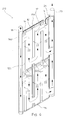
- the plate type heat exchanger 10 is produced starting from two metal plates 12 and 14, for example rectangular in shape, preferably having the same dimensions.
- Said plates 12 and 14 are juxtaposed and are welded together at respective perimetric sides 13a, 13b, 13c, 13d, and at a plurality of welding tracts 22, arranged in alignments (in said figures four alignments have been shown: generally speaking, these alignments are at least two in number), parallel and adjacent to a couple of opposite perimetric sides (13a and 13c in the illustrated example) of the plates 12 and 14 themselves, and in pre-established spaced relationship from them.
- the distance between two alignments of welding tracts 22 is constant and is equal to the distance between the perimetric sides 13a and 13c and the respective adjacent welding tracts 22 (figure 4a).
- the welding tracts 22 have a limited length, and in practice are welding "spots" (where the welding area is punctiform).
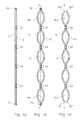
- a fluid under pressure is introduced between said metal plates 12 and 14 that are juxtaposed to form a hollow body 17, substantially box-shaped, preferably flattened, for example with a parallelepiped form, wherein it is defined an internal chamber 16 and two substantially tubular passages 16a and 16b, formed between said couple of opposite perimetric sides 13a and 13c and the respective adjacent alignments of the welding tracts 22, said substantially tubular passages having an axis parallel to said opposite perimetric sides 13a and 13c, and being in fluid communication with said internal chamber 16 (figure 4b).
- the method comprises the operative steps of cutting said hollow body 17 along said substantially tubular passages 16a and 16b and in the direction of their axis, thus obtaining, on the opposite sides of said hollow body, substantially semi-tubular passages 16c and 16d, open towards the outside of the body in question (figure 4c).
- respective distributor 18 and collector ducts 20 are associated with said substantially semi-tubular passages 16c and 16d, destined to distribute and respectively collect a heat exchanger operative fluid into and from said internal chamber 16.
- the distributor 18 and collector 20 ducts are cylindrical.
- the internal chamber 16 is in fluid communication with the exterior of the heat exchanger through an inlet opening and an outlet opening for said operative fluid. More precisely, the inlet opening is in fluid communication with the distributor duct 18, while the outlet opening is in fluid communication with the collector duct 20.
- the distributor duct 18 and the collector duct 20 are welded on the substantially semi-tubular passages 16c and 16d, close to respective end tracts 16c' and 16c'' and 16d' and 16d" thereof respectively, which have been appropriately opened wide apart to house said distributor duct 18 and collector duct 20.
- said operative step is performed by an automated welding device which performs autogenous welding, preferably by means of laser beams.
- Said device performs two weldings 24 and 26 on the distributor duct 18 and two weldings 25 and 27 on the collector duct 20, said weldings being continuous and in a longitudinal direction, substantially symmetrical with each other in relation to the symmetric plane A-A of the heat exchanger 10 to be realized.
- the weldings 24 and 26, and respectively, the weldings 25 and 27 are performed along generants of the distributor duct 18 and the collector duct 20 which are substantially symmetrical with each other in relation to the symmetric plane A-A of the heat exchanger 10 to be realized.
- the two weldings 24 and 26, and respectively 25 and 27 define two portions of duct, where the duct portion, which faces the internal chamber 16 where the heat exchange operative fluid flows, presents suitable openings 28 (for example holes) to put the heat exchange operative fluid in fluid communication with the internal chamber 16.
- the two couples of weldings 24 and 26, and respectively the weldings 25 and 27 are diametrically opposite and are parallel to the plates 12 and 14. More precisely, the weldings 24 and 26, and respectively 25 and 27, lay on plane L-L and L'-L' respectively, substantially perpendicular to the plane of symmetry A-A of the heat exchanger 10 to be realized.
- FIG. 5 shows a second embodiment of a plate type heat exchanger, produced according to the method of the invention, said exchanger being identified with the numeral 110.
- the heat exchanger 110 differs from the heat exchanger 10 in that the weldings 24 and 26, and respectively 25 and 27, parallel to the plates 12 and 14, lay on plane X-X and Y-Y, and X'-X' and Y'-Y' respectively, incident to the axis of the distributor duct 18 and the collector duct 20 and forming respective acute angles that are substantially equal ( ⁇ , ⁇ ') in relation to the plane L-L and L' -L' , to which the axis of the distributor duct 18 and the collector duct 20 belongs.
- the two weldings 24 and 26 are symmetrical in relation to the plane of symmetry A-A of the heat exchanger 110 to be realized, and lay on plane X-X and Y-Y which are symmetrical in relation to the plane of symmetry A-A and which are set at an acute angle ⁇ in relation to the plane L-L, perpendicular to the plane A-A.
- the acute angle ⁇ is between 0° and 50°, according to the diameter of the distributor duct 18 and the collector duct 20.
- the acute angles ⁇ and ⁇ ' are between 10° and 45°.
- the distance between the weldings 24 and 26, and the adjacent alignment of welding tracts 22 is reduced, advantageously providing the heat exchanger 110 with greater mechanical strength.
- the heat exchanger 110 is suitable for use in the majority of the fields of application, including those in which the heat exchanger is subjected to considerable mechanical stress.
- FIG. 6 shows a third embodiment of a heat exchanger produced according to the method of the invention, said exchanger being identified with the numeral 210.
- the structural elements that are identical or operatively equivalent to those of the heat exchanger 10 shown in figure 2 described above, will be identified with the same numerals and will not be described any further.
- the pumping step of the fluid under pressure used to form the hollow body is performed without the complication of the external restraining elements used in the prior art, since it is possible to choose the distance between the weldings of the perimetric sides and the adjacent alignment of the welding tracts, equal to the distance between two alignments of adjacent welding tracts (figure 4a): in this manner the fluid under pressure swells the "ducts" of the internal chamber and the two substantially tubular passages (figure 4b), in a uniform and simultaneous manner.
- heat exchanger is obtained under easy production conditions and at lower cost compared to heat exchangers according to the prior art.
- heat exchangers can be realized, customized for the use in chemical reactors where there is a great difference in pressure between the exterior and the interior of the heat exchanger itself.
- the distributor duct provides the advantageous effect of making usable for the heat exchange also an initial zone of the internal chamber (in other words, the zone that is in close to said distributor duct).
- the heat exchange operative fluid is distributed in a uniform and homogeneous manner along the whole side of the heat exchanger where the distributor duct is provided, already at the side in question.
Landscapes
- Chemical & Material Sciences (AREA)
- Engineering & Computer Science (AREA)
- Physics & Mathematics (AREA)
- Organic Chemistry (AREA)
- Chemical Kinetics & Catalysis (AREA)
- Thermal Sciences (AREA)
- Mechanical Engineering (AREA)
- General Engineering & Computer Science (AREA)
- Fluid Mechanics (AREA)
- Heat-Exchange Devices With Radiators And Conduit Assemblies (AREA)
Priority Applications (12)
| Application Number | Priority Date | Filing Date | Title |
|---|---|---|---|
| EP05025208A EP1788335A1 (fr) | 2005-11-18 | 2005-11-18 | Procédé de fabrication d'un échangeur de chaleur à plaques et échangeur de chaleur correspondant |
| BRPI0618619-0A BRPI0618619A2 (pt) | 2005-11-18 | 2006-10-31 | método para a produção de um trocador de calor do tipo de placa e trocador de calor relacionado |
| CN2006800424549A CN101310156B (zh) | 2005-11-18 | 2006-10-31 | 板型热交换器的制造方法和相关的热交换器 |
| AU2006314788A AU2006314788A1 (en) | 2005-11-18 | 2006-10-31 | Method for the production of a plate type heat exchanger and related heat exchanger |
| CA002629489A CA2629489A1 (fr) | 2005-11-18 | 2006-10-31 | Procede destine a la production d'un echangeur de chaleur a plaques et echangeur de chaleur utilise par ledit procede |
| EP06818325A EP1952083B1 (fr) | 2005-11-18 | 2006-10-31 | Procede destine a la production d'un echangeur de chaleur a plaques et echangeur de chaleur utilise par ledit procede |
| US12/091,520 US7941921B2 (en) | 2005-11-18 | 2006-10-31 | Method for the production of a plate type heat exchanger and related heat exchanger |
| RU2008123726/06A RU2404396C2 (ru) | 2005-11-18 | 2006-10-31 | Теплообменник пластинчатого типа и способ его изготовления |
| PCT/EP2006/010444 WO2007057103A1 (fr) | 2005-11-18 | 2006-10-31 | Procede destine a la production d’un echangeur de chaleur a plaques et echangeur de chaleur utilise par ledit procede |
| AT06818325T ATE554360T1 (de) | 2005-11-18 | 2006-10-31 | Verfahren zur herstellung eines plattenwärmeaustauscher und verwandter wärmeaustauscher |
| MYPI20064452A MY146314A (en) | 2005-11-18 | 2006-11-06 | Method for the production of a plate type heat exchanger and related heat exchanger |
| ARP060104977A AR057574A1 (es) | 2005-11-18 | 2006-11-14 | Metodo para la produccion de un intercambiador de calor tipo placa e intercambiador de calor relacionado |
Applications Claiming Priority (1)
| Application Number | Priority Date | Filing Date | Title |
|---|---|---|---|
| EP05025208A EP1788335A1 (fr) | 2005-11-18 | 2005-11-18 | Procédé de fabrication d'un échangeur de chaleur à plaques et échangeur de chaleur correspondant |
Publications (1)
| Publication Number | Publication Date |
|---|---|
| EP1788335A1 true EP1788335A1 (fr) | 2007-05-23 |
Family
ID=36143226
Family Applications (2)
| Application Number | Title | Priority Date | Filing Date |
|---|---|---|---|
| EP05025208A Withdrawn EP1788335A1 (fr) | 2005-11-18 | 2005-11-18 | Procédé de fabrication d'un échangeur de chaleur à plaques et échangeur de chaleur correspondant |
| EP06818325A Active EP1952083B1 (fr) | 2005-11-18 | 2006-10-31 | Procede destine a la production d'un echangeur de chaleur a plaques et echangeur de chaleur utilise par ledit procede |
Family Applications After (1)
| Application Number | Title | Priority Date | Filing Date |
|---|---|---|---|
| EP06818325A Active EP1952083B1 (fr) | 2005-11-18 | 2006-10-31 | Procede destine a la production d'un echangeur de chaleur a plaques et echangeur de chaleur utilise par ledit procede |
Country Status (11)
| Country | Link |
|---|---|
| US (1) | US7941921B2 (fr) |
| EP (2) | EP1788335A1 (fr) |
| CN (1) | CN101310156B (fr) |
| AR (1) | AR057574A1 (fr) |
| AT (1) | ATE554360T1 (fr) |
| AU (1) | AU2006314788A1 (fr) |
| BR (1) | BRPI0618619A2 (fr) |
| CA (1) | CA2629489A1 (fr) |
| MY (1) | MY146314A (fr) |
| RU (1) | RU2404396C2 (fr) |
| WO (1) | WO2007057103A1 (fr) |
Cited By (11)
| Publication number | Priority date | Publication date | Assignee | Title |
|---|---|---|---|---|
| CH700886A1 (de) * | 2009-04-17 | 2010-10-29 | M & M En Forschung Anstalt | Flachwärmetauscher, sowie Verfahren zu dessen Herstellung. |
| WO2013025802A2 (fr) | 2011-08-15 | 2013-02-21 | The Abell Foundation, Inc. | Transfert de chaleur entre des fluides |
| JP2014524540A (ja) * | 2011-08-15 | 2014-09-22 | ジ アベル ファウンデーション, インコーポレイテッド | 海洋熱エネルギー変換発電プラント |
| US9086057B2 (en) | 2010-01-21 | 2015-07-21 | The Abell Foundation, Inc. | Ocean thermal energy conversion cold water pipe |
| US9151279B2 (en) | 2011-08-15 | 2015-10-06 | The Abell Foundation, Inc. | Ocean thermal energy conversion power plant cold water pipe connection |
| WO2016067245A1 (fr) * | 2014-10-30 | 2016-05-06 | Sabic Global Technologies B.V. | Réacteur comprenant des plaques de refroidissement placées radialement et ses procédés d'utilisation |
| US9797386B2 (en) | 2010-01-21 | 2017-10-24 | The Abell Foundation, Inc. | Ocean thermal energy conversion power plant |
| US10035120B2 (en) | 2014-10-31 | 2018-07-31 | Sabic Global Technologies B.V. | Reactors for separating wax products from lightweight gaseous products of a reaction |
| US10184457B2 (en) | 2010-01-21 | 2019-01-22 | The Abell Foundation, Inc. | Ocean thermal energy conversion plant |
| US10619944B2 (en) | 2012-10-16 | 2020-04-14 | The Abell Foundation, Inc. | Heat exchanger including manifold |
| EP4166883A1 (fr) * | 2021-10-18 | 2023-04-19 | Jun He Technology Co., Ltd. | Échangeur de chaleur |
Families Citing this family (14)
| Publication number | Priority date | Publication date | Assignee | Title |
|---|---|---|---|---|
| EP2018906A1 (fr) | 2007-07-19 | 2009-01-28 | Methanol Casale S.A. | Echangeur de chaleur pour réacteurs chimiques isothermes |
| CN101977680A (zh) * | 2008-01-28 | 2011-02-16 | 弗雷穆特·J·马罗尔德 | 多列式热板和配备多列式热板的换热器 |
| EP2283919A1 (fr) * | 2009-08-13 | 2011-02-16 | Methanol Casale S.A. | Échangeur thermique à plaque pour réacteurs chimiques isothermes |
| AT12048U1 (de) * | 2010-03-23 | 2011-09-15 | Stefan Ing Petters | Vorrichtung zur übertragung von wärme |
| US8869398B2 (en) * | 2011-09-08 | 2014-10-28 | Thermo-Pur Technologies, LLC | System and method for manufacturing a heat exchanger |
| KR101317373B1 (ko) * | 2011-12-09 | 2013-10-10 | 현대자동차주식회사 | 열교환기 |
| US9459054B2 (en) * | 2012-05-04 | 2016-10-04 | Solex Thermal Science Inc. | Heat exchanger for cooling bulk solids |
| US20140096555A1 (en) * | 2012-10-10 | 2014-04-10 | American Sino Heat Transfer LLC | Plate evaporative condenser and cooler |
| CN103851837A (zh) * | 2014-03-24 | 2014-06-11 | 吴江市金鑫冷暖设备制造有限公司 | 中空板式冷凝器板及生产方法 |
| US20180156548A1 (en) * | 2016-12-05 | 2018-06-07 | S&G Co.,Ltd | Plate heat exchanger integrated with pipeline |
| DE102017129749A1 (de) * | 2017-12-13 | 2019-06-13 | Webasto SE | Plattenwärmetauscher |
| JP7018814B2 (ja) * | 2018-04-19 | 2022-02-14 | 株式会社ユタカ技研 | 熱交換器 |
| PT3792578T (pt) * | 2019-09-13 | 2023-10-19 | Alfa Laval Corp Ab | Placa de permutador de calor e permutador de calor de placas para tratamento de uma alimentação líquida |
| EP4286043A1 (fr) | 2022-05-31 | 2023-12-06 | Walter Tosto S.p.A. | Réacteur catalytique avec unité d'échange de chaleur |
Citations (3)
| Publication number | Priority date | Publication date | Assignee | Title |
|---|---|---|---|---|
| GB1167090A (en) * | 1966-03-17 | 1969-10-15 | Onmia Spojene Strojarne A Smal | Method of Manufacturing Heating or Cooling Panel-Type Radiators. |
| WO2001014080A1 (fr) * | 1999-08-20 | 2001-03-01 | Max Roth | Echangeur de chaleur |
| EP1321733A2 (fr) * | 2001-12-14 | 2003-06-25 | Valeo Termico S.A. | Echangeur de chaleur liquide-air, plus particulièrement pour véhicule automobile, et procédé de fabrication d' un tel échangeur |
Family Cites Families (7)
| Publication number | Priority date | Publication date | Assignee | Title |
|---|---|---|---|---|
| US2944328A (en) * | 1954-07-16 | 1960-07-12 | Olin Mathieson | Method of making heat exchanger |
| US3757855A (en) * | 1971-10-15 | 1973-09-11 | Union Carbide Corp | Primary surface heat exchanger |
| FR2771802B1 (fr) * | 1997-12-02 | 2000-01-28 | Dietrich & Cie De | Echangeur de chaleur metallique emaille et sensiblement plat |
| EP1221339A1 (fr) * | 2001-01-05 | 2002-07-10 | Methanol Casale S.A. | Réacteur catalytique avec échangeur de chaleur pour des réactions chimiques endothermiques ou exothermiques |
| EP1306126A1 (fr) * | 2001-10-19 | 2003-05-02 | Methanol Casale S.A. | Echangeur de chaleur pour réacteurs chimiques isothermes |
| EP1376040A1 (fr) * | 2002-06-28 | 2004-01-02 | Methanol Casale S.A. | Unité d'échange de chaleur multiservice |
| EP1447128A1 (fr) * | 2003-02-17 | 2004-08-18 | Methanol Casale S.A. | Procédé pour effectuer des réactions chimiques dans des conditions pseudo-isothermiques |
-
2005
- 2005-11-18 EP EP05025208A patent/EP1788335A1/fr not_active Withdrawn
-
2006
- 2006-10-31 RU RU2008123726/06A patent/RU2404396C2/ru active
- 2006-10-31 AT AT06818325T patent/ATE554360T1/de active
- 2006-10-31 US US12/091,520 patent/US7941921B2/en active Active
- 2006-10-31 WO PCT/EP2006/010444 patent/WO2007057103A1/fr active Application Filing
- 2006-10-31 CN CN2006800424549A patent/CN101310156B/zh active Active
- 2006-10-31 BR BRPI0618619-0A patent/BRPI0618619A2/pt not_active Application Discontinuation
- 2006-10-31 CA CA002629489A patent/CA2629489A1/fr not_active Abandoned
- 2006-10-31 AU AU2006314788A patent/AU2006314788A1/en not_active Abandoned
- 2006-10-31 EP EP06818325A patent/EP1952083B1/fr active Active
- 2006-11-06 MY MYPI20064452A patent/MY146314A/en unknown
- 2006-11-14 AR ARP060104977A patent/AR057574A1/es unknown
Patent Citations (3)
| Publication number | Priority date | Publication date | Assignee | Title |
|---|---|---|---|---|
| GB1167090A (en) * | 1966-03-17 | 1969-10-15 | Onmia Spojene Strojarne A Smal | Method of Manufacturing Heating or Cooling Panel-Type Radiators. |
| WO2001014080A1 (fr) * | 1999-08-20 | 2001-03-01 | Max Roth | Echangeur de chaleur |
| EP1321733A2 (fr) * | 2001-12-14 | 2003-06-25 | Valeo Termico S.A. | Echangeur de chaleur liquide-air, plus particulièrement pour véhicule automobile, et procédé de fabrication d' un tel échangeur |
Cited By (21)
| Publication number | Priority date | Publication date | Assignee | Title |
|---|---|---|---|---|
| CH700886A1 (de) * | 2009-04-17 | 2010-10-29 | M & M En Forschung Anstalt | Flachwärmetauscher, sowie Verfahren zu dessen Herstellung. |
| US9797386B2 (en) | 2010-01-21 | 2017-10-24 | The Abell Foundation, Inc. | Ocean thermal energy conversion power plant |
| US11859597B2 (en) | 2010-01-21 | 2024-01-02 | The Abell Foundation, Inc. | Ocean thermal energy conversion power plant |
| US11371490B2 (en) | 2010-01-21 | 2022-06-28 | The Abell Foundation, Inc. | Ocean thermal energy conversion power plant |
| US10844848B2 (en) | 2010-01-21 | 2020-11-24 | The Abell Foundation, Inc. | Ocean thermal energy conversion power plant |
| US10184457B2 (en) | 2010-01-21 | 2019-01-22 | The Abell Foundation, Inc. | Ocean thermal energy conversion plant |
| US9086057B2 (en) | 2010-01-21 | 2015-07-21 | The Abell Foundation, Inc. | Ocean thermal energy conversion cold water pipe |
| EP2758662A4 (fr) * | 2011-08-15 | 2015-04-01 | Abell Foundation Inc | Transfert de chaleur entre des fluides |
| JP2021046863A (ja) * | 2011-08-15 | 2021-03-25 | ジ アベル ファウンデーション, インコーポレイテッド | 海洋熱エネルギー変換発電プラント |
| JP2017082798A (ja) * | 2011-08-15 | 2017-05-18 | ジ アベル ファウンデーション, インコーポレイテッド | 海洋熱エネルギー変換発電プラント |
| US9151279B2 (en) | 2011-08-15 | 2015-10-06 | The Abell Foundation, Inc. | Ocean thermal energy conversion power plant cold water pipe connection |
| US9909571B2 (en) | 2011-08-15 | 2018-03-06 | The Abell Foundation, Inc. | Ocean thermal energy conversion power plant cold water pipe connection |
| WO2013025802A2 (fr) | 2011-08-15 | 2013-02-21 | The Abell Foundation, Inc. | Transfert de chaleur entre des fluides |
| JP2014524540A (ja) * | 2011-08-15 | 2014-09-22 | ジ アベル ファウンデーション, インコーポレイテッド | 海洋熱エネルギー変換発電プラント |
| EP2758662A2 (fr) * | 2011-08-15 | 2014-07-30 | The Abell Foundation Inc. | Transfert de chaleur entre des fluides |
| JP2014524560A (ja) * | 2011-08-15 | 2014-09-22 | ジ アベル ファウンデーション, インコーポレイテッド | 流体間の熱の伝達 |
| US10619944B2 (en) | 2012-10-16 | 2020-04-14 | The Abell Foundation, Inc. | Heat exchanger including manifold |
| WO2016067245A1 (fr) * | 2014-10-30 | 2016-05-06 | Sabic Global Technologies B.V. | Réacteur comprenant des plaques de refroidissement placées radialement et ses procédés d'utilisation |
| US10525427B2 (en) | 2014-10-30 | 2020-01-07 | Sabic Global Technologies B.V. | Reactor comprising radially placed cooling plates and methods of using same |
| US10035120B2 (en) | 2014-10-31 | 2018-07-31 | Sabic Global Technologies B.V. | Reactors for separating wax products from lightweight gaseous products of a reaction |
| EP4166883A1 (fr) * | 2021-10-18 | 2023-04-19 | Jun He Technology Co., Ltd. | Échangeur de chaleur |
Also Published As
| Publication number | Publication date |
|---|---|
| WO2007057103A1 (fr) | 2007-05-24 |
| EP1952083B1 (fr) | 2012-04-18 |
| MY146314A (en) | 2012-07-31 |
| ATE554360T1 (de) | 2012-05-15 |
| CN101310156A (zh) | 2008-11-19 |
| BRPI0618619A2 (pt) | 2011-09-06 |
| AR057574A1 (es) | 2007-12-05 |
| RU2404396C2 (ru) | 2010-11-20 |
| CA2629489A1 (fr) | 2007-05-24 |
| RU2008123726A (ru) | 2009-12-27 |
| US7941921B2 (en) | 2011-05-17 |
| CN101310156B (zh) | 2010-09-08 |
| US20080314574A1 (en) | 2008-12-25 |
| EP1952083A1 (fr) | 2008-08-06 |
| AU2006314788A1 (en) | 2007-05-24 |
Similar Documents
| Publication | Publication Date | Title |
|---|---|---|
| EP1952083B1 (fr) | Procede destine a la production d'un echangeur de chaleur a plaques et echangeur de chaleur utilise par ledit procede | |
| US7055583B2 (en) | Heat exchange unit for isothermal chemical reactors | |
| EP1748840B1 (fr) | Echangeur de chaleur a plaques | |
| AU2002347040A1 (en) | Heat exchange unit for isothermal chemical reactors | |
| EP2464450B1 (fr) | Échangeur thermique à plaque pour réacteurs chimiques isothermes | |
| WO1998055812A1 (fr) | Echangeur de chaleur et/ou dispositif de melange de fluide | |
| EP2594884B1 (fr) | Échangeur thermique à plaques et procédé de fabrication d'un échangeur thermique à plaques | |
| EP1363729B1 (fr) | Procede permettant de realiser des reactions chimiques dans des conditions pseudo-isothermiques | |
| EP1957191B1 (fr) | Echangeur thermique de type plaque pour un reacteur chimique isotherme | |
| CA2463047C (fr) | Procede et reacteur permettant d'effectuer des reactions chimiques dans des conditions pseudo-isothermes | |
| RU2356616C2 (ru) | Псевдоизотермический химический реактор высокого давления | |
| EP1279915A1 (fr) | Unité d'échange de chaleur, en particulier pour réacteurs isothermes | |
| EP1321184A1 (fr) | Réacteur de reformage à la vapeur d'eau | |
| EP4286043A1 (fr) | Réacteur catalytique avec unité d'échange de chaleur | |
| MXPA06009962A (en) | Plate-type heat-exchanger |
Legal Events
| Date | Code | Title | Description |
|---|---|---|---|
| PUAI | Public reference made under article 153(3) epc to a published international application that has entered the european phase |
Free format text: ORIGINAL CODE: 0009012 |
|
| AK | Designated contracting states |
Kind code of ref document: A1 Designated state(s): AT BE BG CH CY CZ DE DK EE ES FI FR GB GR HU IE IS IT LI LT LU LV MC NL PL PT RO SE SI SK TR |
|
| AX | Request for extension of the european patent |
Extension state: AL BA HR MK YU |
|
| AKX | Designation fees paid | ||
| REG | Reference to a national code |
Ref country code: DE Ref legal event code: 8566 |
|
| STAA | Information on the status of an ep patent application or granted ep patent |
Free format text: STATUS: THE APPLICATION IS DEEMED TO BE WITHDRAWN |
|
| 18D | Application deemed to be withdrawn |
Effective date: 20071124 |