EP1788262A1 - Kurbelwellenlagereinrichtung - Google Patents
Kurbelwellenlagereinrichtung Download PDFInfo
- Publication number
- EP1788262A1 EP1788262A1 EP06124087A EP06124087A EP1788262A1 EP 1788262 A1 EP1788262 A1 EP 1788262A1 EP 06124087 A EP06124087 A EP 06124087A EP 06124087 A EP06124087 A EP 06124087A EP 1788262 A1 EP1788262 A1 EP 1788262A1
- Authority
- EP
- European Patent Office
- Prior art keywords
- crankshaft
- bearing
- crankcase
- bearing assembly
- crankshaft bearing
- Prior art date
- Legal status (The legal status is an assumption and is not a legal conclusion. Google has not performed a legal analysis and makes no representation as to the accuracy of the status listed.)
- Granted
Links
Images


Classifications
-
- F—MECHANICAL ENGINEERING; LIGHTING; HEATING; WEAPONS; BLASTING
- F16—ENGINEERING ELEMENTS AND UNITS; GENERAL MEASURES FOR PRODUCING AND MAINTAINING EFFECTIVE FUNCTIONING OF MACHINES OR INSTALLATIONS; THERMAL INSULATION IN GENERAL
- F16C—SHAFTS; FLEXIBLE SHAFTS; ELEMENTS OR CRANKSHAFT MECHANISMS; ROTARY BODIES OTHER THAN GEARING ELEMENTS; BEARINGS
- F16C9/00—Bearings for crankshafts or connecting-rods; Attachment of connecting-rods
- F16C9/02—Crankshaft bearings
-
- F—MECHANICAL ENGINEERING; LIGHTING; HEATING; WEAPONS; BLASTING
- F02—COMBUSTION ENGINES; HOT-GAS OR COMBUSTION-PRODUCT ENGINE PLANTS
- F02F—CYLINDERS, PISTONS OR CASINGS, FOR COMBUSTION ENGINES; ARRANGEMENTS OF SEALINGS IN COMBUSTION ENGINES
- F02F7/00—Casings, e.g. crankcases or frames
- F02F7/0043—Arrangements of mechanical drive elements
- F02F7/0053—Crankshaft bearings fitted in the crankcase
Definitions
- the present invention relates generally to crankshaft bearings for internal combustion engines and in particular to crankshaft friction bearings for internal combustion engines.
- engine blocks and their main bearing caps are increasingly made from cast aluminum for their weight-saving potential.
- cast aluminum engine blocks and main bearing caps are typically bulkier than their cast iron counterparts to compensate for the substantially inferior tensile strengths typically displayed by cast aluminum parts thereby negating some of the weight saving advantage previously mentioned.
- engine manufacturers have combined cast aluminum engine blocks with cast iron main bearing caps.
- cast iron main bearing caps with aluminum engine cylinder blocks or crankcases requires more complex and difficult machining and increases the weight of the engine.
- crankshaft bearing assembly that alleviates some of the drawbacks of conventional crankshaft bearing assembly and improves the durability of the engine in which the crankshaft bearing assembly is used.
- One aspect of the present invention is to provide a crankshaft bearing assembly for a cast aluminum engine in which at least one bearing cap is made of an aluminum having a tensile strength higher than the tensile strength of the aluminum of the engine or crankcase.
- crankshaft bearing assembly for supporting a crankshaft for rotation about a crankshaft axis within an engine having a crankcase
- the crankshaft bearing assembly including at least one crankshaft bearing divided into a first half and a second half, the first half being integral with the crankcase, and the second half being a bearing cap connectable to the crankcase;
- the crankcase being made of a first aluminum alloy having a first tensile strength
- the bearing cap being made of a second aluminum alloy having a second tensile strength higher than the first tensile strength, the second tensile strength of the second aluminum alloy being at least 300 MPa.
- first aluminum alloy is a cast alloy and the second aluminum alloy is a wrought alloy.
- first half of the bearing is made by casting and the second half of the bearing is made by forging.
- the first aluminum alloy possesses a tensile strength of at most 250 MPa and the second aluminum alloy possesses a tensile strength of a least 350 MPa.
- crankshaft bearing includes a bearing bore, the bearing bore being split by the division of the crankshaft bearing and bearing bushings are disposed within the bearing bore.
- crankshaft bearing includes a first crankshaft bearing having a first bearing cap and a second crankshaft bearing having a second bearing cap, the first and the second bearing cap being made in one piece.
- the crankcase includes lateral extensions disposed on each sides of the bearing cap, the bearing cap being bolted to the lateral extensions of the crankcase.
- crankshaft bearing assembly further comprises a crankcase lower half, at least one of an end bearing cap being integral with the crankcase lower half.
- Another aspect of the present invention is to provide an internal combustion engine comprising a crankshaft bearing assembly in which at least one bearing cap is made of an aluminum having a tensile strength higher than the tensile strength of the aluminum of the crankcase, the internal combustion engine having at least two cylinders and a power unit case having a crankcase and an integral transmission housing accommodating at least a transmission shaft.
- the invention provides a motorcycle having an internal combustion chamber, the internal combustion engine having at least two cylinders, a crankshaft and a crankshaft bearing assembly for supporting the crankshaft within a power unit case having a crankcase and an integral transmission housing accommodating at least a transmission shaft;
- the crankshaft bearing assembly including at least one crankshaft bearing divided into a first half and a second half, the first half being integral with the crankcase, and the second half being a bearing cap connectable to the crankcase;
- the crankcase being made of a first aluminum alloy having a first tensile strength and the bearing cap being made of a second aluminum alloy having a second tensile strength higher than the first tensile strength, the second tensile strength of the second aluminum alloy being at least 300 MPa.
- a further aspect of the invention of the present invention is to provide an All Terrain Vehicle (ATV) having an internal combustion chamber, the internal combustion engine having at least two cylinders, a crankshaft and a crankshaft bearing assembly for supporting the crankshaft within a power unit case having a crankcase and an integral transmission housing accommodating at least a transmission shaft;
- the crankshaft bearing assembly including at least one crankshaft bearing divided into a first half and a second half, the first half being integral with the crankcase, and the second half being a bearing cap connectable to the crankcase;
- the crankcase being made of a first aluminum alloy having a first tensile strength and the bearing cap being made of a second aluminum alloy having a second tensile strength higher than the first tensile strength, the second tensile strength of the second aluminum alloy being at least 300 MPa.
- Embodiments of the present invention each have at least one of the above-mentioned aspects, but not necessarily have all of them.
- FIG. 1 is a longitudinal cross-sectional view of a crankshaft mounted into a crankcase of an internal combustion engine via a crankshaft bearing assembly in accordance with one embodiment of the invention
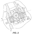
- FIG. 2 is a cross-sectional view of a crankshaft bearing assembly taken at line A-A of Figure 1.
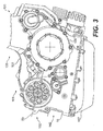
- FIG.3 is a side elevational view of an internal combustion engine incorporating a crankshaft bearing assembly in accordance with one embodiment of the invention
- FIG. 4 is a side elevational view of a motorcycle having an internal combustion engine as shown in FIG.3;
- FIG.5 a side elevational view of a All-Terrain Vehicle (ATV) having an internal combustion engine as shown in FIG. 3.
- ATV All-Terrain Vehicle
- crankshaft 10 is shown supported within the crankcase of an internal combustion engine, the lower portion of the crankcase being defined by a lower crankcase half 15 (shown partially).
- the crankshaft 10 is mounted onto the lower portion of the crankcase upper half 12 for rotational movement via three main bearing assemblies 20, 22 and 24 so as to rotate about a shaft axis 26.
- the crankcase upper half 12 in this particular embodiment is the bottom portion of the cylinder block itself. In other embodiment, the crankcase upper half may separate from the cylinders.
- the end journals 14, 16 of the crankshaft 10 are supported for rotation by the main bearing assemblies 20, 22 while the central main journal 18 is supported by the main bearing assembly 24.
- crankshaft bearing assemblies 20, 22 and 24 Two pistons (not shown) with corresponding connecting rods 28 and 30 are respectively connected to the rod journals 32 and 34 of the crankshaft 10 so as to be able to rotate thereon and impart rotational motion to the crankshaft 10.
- the upper halves of the main bearing assemblies 20, 22 and 24 are machined from the crankcase upper half 12 and are therefore integral with the latter.
- the lower halves 38, 40 and 42 of the main bearing assemblies 20, 22 and 24 consist of bearing caps bolted or otherwise secured to the crankcase upper half 12 in alignment with the upper halves of the main bearing assemblies 20, 22 and 24 thereby enveloping the crankshaft journals 14, 16 and 18 and securing the crankshaft 10 to the crankcase.
- the upper halves and the lower halves 38, 40 and 42 of the main bearing assemblies 20, 22 and 24 together defined crankshaft bearing bores.
- Lubricating oil is routed to the main journals 14, 16 and 18 of the crankshaft 10 and therefore to the main bearing assemblies 20, 22 and 24 through an internal conduit 36 in the crankshaft 10 to provide adequate lubricant to the main bearing assemblies 20, 22 and 24.
- the lubricating oil enters from a pressurized oil chamber 25 into the main conduit 35 and is directed to the internal conduit 36 leading to the main bearing assemblies 20, 22 and 24.
- the crankcase upper half 12 is made of a first cast aluminum having a tensile strength of about 200MPa and at most 250MPa whereas the bearing cap 40 is made of a wrought aluminum alloy having a tensile strength of at least 300MPa and is able to sustain the heavy stresses applied to the main bearing assembly 24 located in the center of the engine.
- Cast aluminum alloys typically have high Si content, whereas wrought aluminum alloys typically have low Si content and higher tensile strength.
- the bearing cap 40 is made of a wrought aluminum alloy having a tensile strength of at least 350MPa.
- the bearing cap 40 can also be made from a cast aluminum alloy that has been forged giving is under tensile strength of at least 300MPa and upward of 350MPa.
- the lower halves 38 and 42 of end bearing assemblies 20, 22 are machined from the lower crankcase half 15 and are therefore integral therewith.
- the crankcase lower half 15 is made of a cast aluminum similar to the crankcase upper half 12 having a tensile strength of about 200MPa.
- the lower halves 38 and 42 of end bearing assemblies 20, 22 are bearing caps similar to the bearing cap 40 are made of wrought or forged aluminum alloy having a tensile strength of at least 300MPa.
- FIG.2. which is a cross section of the main bearing assembly 24, it can be seen that the crankcase is divided essentially horizontally on a separating plane 50, the upper portion being defined by the crankcase upper half 12 and the lower portion being defined by the crankcase lower half 15
- the main bearing assembly 24 consists of an upper bearing surface 53 machined directly into the crankcase upper half 12 and a lower bearing surface 54 defined by the inner surface of the bearing cap 40. Between the upper and lower bearing surfaces 53 and 54 and the crankshaft journal 18, there is a small clearance gap 56 to allow ingress of lubricating oil and room to allow a thin oil film to form to improve running characteristics of the crankshaft 10 within the main bearing assembly 24.
- the lubricating oil is introduced into the bearing gap 56 through the internal conduit 36 of the crankshaft 10 as previously described.
- a pair of bearing bushings may be disposed on the upper and lower bearing surfaces 53 and 54 and fitted within the bearing bore of the bearing assembly 24 in between the bearing surfaces and the crankshaft journal 18 as is well known in the art of engine design.
- the lower half 60 of the main bearing assembly 24 is in the form of a bearing cap 40 secured onto the cylinder block 12 by means of at least one bolt 58.
- a total of four bolts 58 are used to secure the bearing cap 40 to the cylinder block 12.
- the crankcase may have lateral extensions or web such that the bearing cap 40 is inserted in between the extensions and secured to the extensions by a set of transversal bolts.
- the upper half 62 of the main bearing assembly 24 is machined from the crankcase upper half 12 and is integral with the crankcase upper half 12.
- the upper half 62 is therefore made of the same cast aluminum as the crankcase upper half 12 and has a tensile strength of at least 200MPa.
- the crankcase upper half 12 is made of a higher grade cast aluminum having a tensile strength of at least 250MPa.
- the bearing cap 40 which is the lower half 60 of the main bearing assembly 24 is made of a wrought aluminum alloy having a tensile strength of at least 300MPa.
- the bearing cap 40 Since the upper half 62 of the main bearing assembly 24 is machined directly into the crankcase upper half 12, it is much more voluminous than the bearing cap 40 and as such it is much stronger and does not require to be made of an aluminum having high tensile strength.
- the bearing cap 40 on the other hand is a small component that, if constructed from a similar cast aluminum as the crankcase upper half 12, would have to be oversized to withstand the large forces exerted on the main bearing assembly 24. If the bearing cap 40 were constructed from a similar cast aluminum as the crankcase upper half 12, the weight reduction potential of using aluminum would be offset by the oversize requirement.
- a bearing cap 40 made of wrought aluminum alloy having a tensile strength of at least 300MPa allows the bearing cap 40 to be smaller and therefore lighter and yet able to withstand the large forces exerted on the main bearing, assembly 24.
- the use of a bearing cap 40 made of aluminum alloy that has been forged and having a tensile strength of at least 300MPa allows the bearing cap 40 to be smaller and therefore lighter and yet able to withstand the large forces exerted on the main bearing assembly 24.
- the lower halves 38 and 42 of end bearing assemblies 20, 22 are bearing caps similar to the bearing cap 40 and are made of wrought or forged aluminum alloys having a tensile strength of at least 300MPa.
- the upper halves of the end bearing assemblies 20, 22 being machined directly into the crankcase upper half 12 are more voluminous and do not require to be made of an aluminum having higher tensile strength.
- the bearing caps on the other hand are small components made of a higher tensile strength than the upper halves such that they can be made smaller and lighter yet able to withstand the large forces exerted on the main bearing assemblies 20 and 22.
- the engine includes four or five main bearing assemblies in accordance with the invention having bearing caps of higher tensile strength aluminum than the upper halves machined into the cast aluminum crankcase.
- the bearing caps may be constructed as units including two or more bearing caps made of a single piece. In this way, the bearing caps may be secured or bolted to the upper halves as a unit.
- an internal combustion engine 100 has an power unit case 101.
- the power unit case 101 includes a crankcase 102 that is divided into a cylinder block portion 103, which includes the upper part of the crankcase 102 and a cylinder block 105, and a lower crankcase half 15 along a separating plane 50.
- An oil sump 107 is secured to the lower crankcase half 15.
- a cylinder head assembly (not shown) sits atop the cylinder block 105.
- the cylinder block 105 has two cylinders (not shown) inside each of which a piston reciprocates. Each of the pistons together with the side wall of its corresponding cylinder and the corresponding portion of the cylinder head assembly forms a combustion chamber (not shown).
- the internal combustion engine 100 of the present invention is preferably a four-cycle engine, at least one intake valve per cylinder (not shown) and at leas one exhaust valve per cylinder (not shown) are provided in file cylinder head assembly. Two intake valves and two exhaust valves per cylinder are preferably provided.
- a fuel injector (not shown) and a spark plug (not shown) per cylinder are also provided in the cylinder head assembly.
- a pair of throttle bodies are used to regulate the quantity of air entering the combustion chambers.
- An air intake manifold (not shown) or an airbox (not shown) or both, are provided upstream of and in fluid communication with the throttle bodies.
- An exhaust manifold (not shown) in fluid communication with each combustion chamber is provided on the side of the cylinder block. The exhaust manifold is in fluid communication with the exhaust system of the vehicle incorporating the engine 100. It would be understood that the engine 100 also has other elements and systems not specifically shown and/or described in the present application. These can include, but are not limited to, a starter motor, an oil filter, a cooling system, an electrical system, and a fuel injection system.
- the power unit case 101 also includes an integrated transmission housing 142 which can be made in integrally with the crankcase 102 or fastened to the crankcase 102, with bolts for example.
- the side part of the power unit case 101 has a first housing cover 108 that is secured by at least one fastener 109, such as a screw, to the crankcase 102.
- the first housing cover 108 forms part of the power unit case 101.
- the first housing cover 108 is an ignition cover which can be removed to provide access to an ignition chamber located in the space inside the power unit case 101 within which the ignition system or generator-ignition system is located.
- the ignition chamber can be part of the crankcase 102 or can be partially separated from the crankcase 102.
- the internal combustion engine 100 can be used to power a motorcycle 300, as shown in fig. 4.
- the motorcycle 300 has two wheels 302a, 302b, a handlebar 304 to steer the front wheel 302a, and a straddle-type seat 306.
- the engine 100 is mounted to the frame 308 of the motorcycle 300 below the seat 306.
- the engine 100 powers the motorcycle 300 by having the output shaft of the transmission operatively connected to the rear wheel 302b via a chain 310.
- the crankshaft bearing assembly in accordance with the present invention enable the designer of the motorcycle 300 to reduce the weight of the motorcycle thereby improving the ratio weight/power.
- the internal combustion engine 100 can also be used to power an all-terrain vehicle (ATV) 350, as shown in fig. 5.
- the ATV 350 has two front wheels 352a, two rear wheels 352b, a handlebar 354 to steer the two front wheels 352a, and a straddle-type seat 356.
- the engine 100 is mounted to the frame 358 of the ATV 350 below the seat 356.
- the engine 100 powers the ATV 350 by having the output shaft of the transmission operatively connected to the two rear wheels 352b via a chain 360.
- the crankshaft bearing assembly in accordance with the present invention enable the designer of the ATV 350 to reduce the weight of the ATV thereby improving the ratio weight/power.
- crankshaft bearing assembly in accordance with the present invention is suitable for use in internal combustion engines including those used to power various motorized recreational vehicles, such as motorcycles, small off-road vehicles (ATV, quads), personal watercrafts (PWC), snowmobiles, sport boats, inboard and outboard engines, aircraft, karts, and small utility vehicles.
- motorized recreational vehicles such as motorcycles, small off-road vehicles (ATV, quads), personal watercrafts (PWC), snowmobiles, sport boats, inboard and outboard engines, aircraft, karts, and small utility vehicles.
Landscapes
- Engineering & Computer Science (AREA)
- General Engineering & Computer Science (AREA)
- Mechanical Engineering (AREA)
- Chemical & Material Sciences (AREA)
- Combustion & Propulsion (AREA)
- Shafts, Cranks, Connecting Bars, And Related Bearings (AREA)
- Cylinder Crankcases Of Internal Combustion Engines (AREA)
- Sliding-Contact Bearings (AREA)
Applications Claiming Priority (1)
| Application Number | Priority Date | Filing Date | Title |
|---|---|---|---|
| EP05110703 | 2005-11-14 |
Publications (2)
| Publication Number | Publication Date |
|---|---|
| EP1788262A1 true EP1788262A1 (de) | 2007-05-23 |
| EP1788262B1 EP1788262B1 (de) | 2008-07-16 |
Family
ID=36130068
Family Applications (1)
| Application Number | Title | Priority Date | Filing Date |
|---|---|---|---|
| EP06124087A Not-in-force EP1788262B1 (de) | 2005-11-14 | 2006-11-14 | Kurbelwellenlagereinrichtung |
Country Status (3)
| Country | Link |
|---|---|
| EP (1) | EP1788262B1 (de) |
| AT (1) | ATE401507T1 (de) |
| DE (1) | DE602006001827D1 (de) |
Cited By (1)
| Publication number | Priority date | Publication date | Assignee | Title |
|---|---|---|---|---|
| FR2942732A1 (fr) * | 2009-03-04 | 2010-09-10 | Peugeot Citroen Automobiles Sa | Dispositif bimatiere, carter et vehicule equipes de ce dispositif et procede de fabrication de ce dispositif |
Citations (4)
| Publication number | Priority date | Publication date | Assignee | Title |
|---|---|---|---|---|
| US2025297A (en) * | 1932-04-30 | 1935-12-24 | Continental Motors Corp | Engine |
| US3089735A (en) * | 1960-06-02 | 1963-05-14 | Fuchs Kg Otto | Reciprocable combustion engine |
| US4651691A (en) * | 1982-05-27 | 1987-03-24 | Nissan Motor Co., Ltd. | Internal combustion engine having aluminum alloy cylinder block |
| JP2000337348A (ja) * | 1999-05-31 | 2000-12-05 | Toyota Motor Corp | クランクシャフト用軸受 |
-
2006
- 2006-11-14 DE DE602006001827T patent/DE602006001827D1/de active Active
- 2006-11-14 EP EP06124087A patent/EP1788262B1/de not_active Not-in-force
- 2006-11-14 AT AT06124087T patent/ATE401507T1/de active
Patent Citations (4)
| Publication number | Priority date | Publication date | Assignee | Title |
|---|---|---|---|---|
| US2025297A (en) * | 1932-04-30 | 1935-12-24 | Continental Motors Corp | Engine |
| US3089735A (en) * | 1960-06-02 | 1963-05-14 | Fuchs Kg Otto | Reciprocable combustion engine |
| US4651691A (en) * | 1982-05-27 | 1987-03-24 | Nissan Motor Co., Ltd. | Internal combustion engine having aluminum alloy cylinder block |
| JP2000337348A (ja) * | 1999-05-31 | 2000-12-05 | Toyota Motor Corp | クランクシャフト用軸受 |
Non-Patent Citations (1)
| Title |
|---|
| PATENT ABSTRACTS OF JAPAN vol. 2000, no. 15 6 April 2001 (2001-04-06) * |
Cited By (2)
| Publication number | Priority date | Publication date | Assignee | Title |
|---|---|---|---|---|
| FR2942732A1 (fr) * | 2009-03-04 | 2010-09-10 | Peugeot Citroen Automobiles Sa | Dispositif bimatiere, carter et vehicule equipes de ce dispositif et procede de fabrication de ce dispositif |
| WO2010100356A1 (fr) * | 2009-03-04 | 2010-09-10 | Peugeot Citroën Automobiles SA | Dispositif bimatière, carter et véhicule équipes de ce dispositif et procédé fabrication de ce dispositif |
Also Published As
| Publication number | Publication date |
|---|---|
| DE602006001827D1 (de) | 2008-08-28 |
| EP1788262B1 (de) | 2008-07-16 |
| ATE401507T1 (de) | 2008-08-15 |
Similar Documents
| Publication | Publication Date | Title |
|---|---|---|
| US20080025658A1 (en) | Friction-bearing assembly for a rotating shaft | |
| Nunney | Light and heavy vehicle technology | |
| US8726869B2 (en) | Internal combustion engine with plate-mounted cam drive system | |
| US7559308B2 (en) | Engine for leisure vehicle | |
| EP2581566B1 (de) | Öldurchgangsstruktur für einen Motor | |
| US7464685B2 (en) | Crankshaft bearing assembly | |
| US3895868A (en) | Structure of internal combustion engines | |
| US7069895B2 (en) | Air intake system of outboard motor | |
| US7325527B2 (en) | Oil pump arrangement for an internal combustion engine | |
| WO1999031371B1 (en) | Engine construction | |
| EP1788262B1 (de) | Kurbelwellenlagereinrichtung | |
| EP1785637B1 (de) | Gleitlagereinrichtung für eine rotierende Welle | |
| EP1785601A1 (de) | Entlüftungsvorrichtung für eine Brennkraftmaschine | |
| JP2009180210A (ja) | 内燃機関およびこれを搭載した車両 | |
| EP1785611B1 (de) | Ölversorgungssystem eines Verbrennungsmotors | |
| Miritsch et al. | Big boxer-the engine in the new bmw r18 | |
| US6382171B1 (en) | Lubricating device for internal combustion engine | |
| US11549549B2 (en) | Engine crankshaft assemblies with internal stiffening structures | |
| JP4175265B2 (ja) | 内燃機関の補機部品取付構造 | |
| CN109209552B (zh) | 用于内燃发动机的曲轴 | |
| Sanders | The New Chevrolet V-8 Engine | |
| Hauk et al. | A Five-Cylinder Engine as an Economical, Smooth-Running Power Plant | |
| Allen et al. | Turbocharging the Chrysler 2.5 Liter Engine | |
| Scarlett | Europe's most interesting engines: Faced with tightening emission and safety legislation, Europe's carmakers offer fascinating powertrain solutions. | |
| Ohrnberger et al. | The new Rotax engine R-1503 for SEA-DOO personal watercraft |
Legal Events
| Date | Code | Title | Description |
|---|---|---|---|
| PUAI | Public reference made under article 153(3) epc to a published international application that has entered the european phase |
Free format text: ORIGINAL CODE: 0009012 |
|
| AK | Designated contracting states |
Kind code of ref document: A1 Designated state(s): AT BE BG CH CY CZ DE DK EE ES FI FR GB GR HU IE IS IT LI LT LU LV MC NL PL PT RO SE SI SK TR |
|
| AX | Request for extension of the european patent |
Extension state: AL BA HR MK YU |
|
| 17P | Request for examination filed |
Effective date: 20071115 |
|
| AKX | Designation fees paid |
Designated state(s): AT BE BG CH CY CZ DE DK EE ES FI FR GB GR HU IE IS IT LI LT LU LV MC NL PL PT RO SE SI SK TR |
|
| GRAP | Despatch of communication of intention to grant a patent |
Free format text: ORIGINAL CODE: EPIDOSNIGR1 |
|
| GRAS | Grant fee paid |
Free format text: ORIGINAL CODE: EPIDOSNIGR3 |
|
| GRAA | (expected) grant |
Free format text: ORIGINAL CODE: 0009210 |
|
| AK | Designated contracting states |
Kind code of ref document: B1 Designated state(s): AT BE BG CH CY CZ DE DK EE ES FI FR GB GR HU IE IS IT LI LT LU LV MC NL PL PT RO SE SI SK TR |
|
| REG | Reference to a national code |
Ref country code: GB Ref legal event code: FG4D |
|
| REG | Reference to a national code |
Ref country code: CH Ref legal event code: EP |
|
| REF | Corresponds to: |
Ref document number: 602006001827 Country of ref document: DE Date of ref document: 20080828 Kind code of ref document: P |
|
| REG | Reference to a national code |
Ref country code: IE Ref legal event code: FG4D |
|
| NLV1 | Nl: lapsed or annulled due to failure to fulfill the requirements of art. 29p and 29m of the patents act | ||
| PG25 | Lapsed in a contracting state [announced via postgrant information from national office to epo] |
Ref country code: NL Free format text: LAPSE BECAUSE OF FAILURE TO SUBMIT A TRANSLATION OF THE DESCRIPTION OR TO PAY THE FEE WITHIN THE PRESCRIBED TIME-LIMIT Effective date: 20080716 Ref country code: LT Free format text: LAPSE BECAUSE OF FAILURE TO SUBMIT A TRANSLATION OF THE DESCRIPTION OR TO PAY THE FEE WITHIN THE PRESCRIBED TIME-LIMIT Effective date: 20080716 Ref country code: IS Free format text: LAPSE BECAUSE OF FAILURE TO SUBMIT A TRANSLATION OF THE DESCRIPTION OR TO PAY THE FEE WITHIN THE PRESCRIBED TIME-LIMIT Effective date: 20081116 |
|
| PG25 | Lapsed in a contracting state [announced via postgrant information from national office to epo] |
Ref country code: BG Free format text: LAPSE BECAUSE OF FAILURE TO SUBMIT A TRANSLATION OF THE DESCRIPTION OR TO PAY THE FEE WITHIN THE PRESCRIBED TIME-LIMIT Effective date: 20081016 Ref country code: PT Free format text: LAPSE BECAUSE OF FAILURE TO SUBMIT A TRANSLATION OF THE DESCRIPTION OR TO PAY THE FEE WITHIN THE PRESCRIBED TIME-LIMIT Effective date: 20081216 Ref country code: LV Free format text: LAPSE BECAUSE OF FAILURE TO SUBMIT A TRANSLATION OF THE DESCRIPTION OR TO PAY THE FEE WITHIN THE PRESCRIBED TIME-LIMIT Effective date: 20080716 Ref country code: ES Free format text: LAPSE BECAUSE OF FAILURE TO SUBMIT A TRANSLATION OF THE DESCRIPTION OR TO PAY THE FEE WITHIN THE PRESCRIBED TIME-LIMIT Effective date: 20081027 Ref country code: FI Free format text: LAPSE BECAUSE OF FAILURE TO SUBMIT A TRANSLATION OF THE DESCRIPTION OR TO PAY THE FEE WITHIN THE PRESCRIBED TIME-LIMIT Effective date: 20080716 Ref country code: SI Free format text: LAPSE BECAUSE OF FAILURE TO SUBMIT A TRANSLATION OF THE DESCRIPTION OR TO PAY THE FEE WITHIN THE PRESCRIBED TIME-LIMIT Effective date: 20080716 |
|
| PG25 | Lapsed in a contracting state [announced via postgrant information from national office to epo] |
Ref country code: BE Free format text: LAPSE BECAUSE OF FAILURE TO SUBMIT A TRANSLATION OF THE DESCRIPTION OR TO PAY THE FEE WITHIN THE PRESCRIBED TIME-LIMIT Effective date: 20080716 |
|
| PG25 | Lapsed in a contracting state [announced via postgrant information from national office to epo] |
Ref country code: DK Free format text: LAPSE BECAUSE OF FAILURE TO SUBMIT A TRANSLATION OF THE DESCRIPTION OR TO PAY THE FEE WITHIN THE PRESCRIBED TIME-LIMIT Effective date: 20080716 Ref country code: EE Free format text: LAPSE BECAUSE OF FAILURE TO SUBMIT A TRANSLATION OF THE DESCRIPTION OR TO PAY THE FEE WITHIN THE PRESCRIBED TIME-LIMIT Effective date: 20080716 |
|
| PLBE | No opposition filed within time limit |
Free format text: ORIGINAL CODE: 0009261 |
|
| STAA | Information on the status of an ep patent application or granted ep patent |
Free format text: STATUS: NO OPPOSITION FILED WITHIN TIME LIMIT |
|
| PG25 | Lapsed in a contracting state [announced via postgrant information from national office to epo] |
Ref country code: SK Free format text: LAPSE BECAUSE OF FAILURE TO SUBMIT A TRANSLATION OF THE DESCRIPTION OR TO PAY THE FEE WITHIN THE PRESCRIBED TIME-LIMIT Effective date: 20080716 Ref country code: CZ Free format text: LAPSE BECAUSE OF FAILURE TO SUBMIT A TRANSLATION OF THE DESCRIPTION OR TO PAY THE FEE WITHIN THE PRESCRIBED TIME-LIMIT Effective date: 20080716 Ref country code: RO Free format text: LAPSE BECAUSE OF FAILURE TO SUBMIT A TRANSLATION OF THE DESCRIPTION OR TO PAY THE FEE WITHIN THE PRESCRIBED TIME-LIMIT Effective date: 20080716 |
|
| 26N | No opposition filed |
Effective date: 20090417 |
|
| PG25 | Lapsed in a contracting state [announced via postgrant information from national office to epo] |
Ref country code: MC Free format text: LAPSE BECAUSE OF NON-PAYMENT OF DUE FEES Effective date: 20081130 |
|
| REG | Reference to a national code |
Ref country code: IE Ref legal event code: MM4A |
|
| REG | Reference to a national code |
Ref country code: FR Ref legal event code: ST Effective date: 20090731 |
|
| PG25 | Lapsed in a contracting state [announced via postgrant information from national office to epo] |
Ref country code: IE Free format text: LAPSE BECAUSE OF NON-PAYMENT OF DUE FEES Effective date: 20081114 |
|
| PG25 | Lapsed in a contracting state [announced via postgrant information from national office to epo] |
Ref country code: SE Free format text: LAPSE BECAUSE OF FAILURE TO SUBMIT A TRANSLATION OF THE DESCRIPTION OR TO PAY THE FEE WITHIN THE PRESCRIBED TIME-LIMIT Effective date: 20081016 |
|
| PG25 | Lapsed in a contracting state [announced via postgrant information from national office to epo] |
Ref country code: PL Free format text: LAPSE BECAUSE OF FAILURE TO SUBMIT A TRANSLATION OF THE DESCRIPTION OR TO PAY THE FEE WITHIN THE PRESCRIBED TIME-LIMIT Effective date: 20080716 |
|
| PG25 | Lapsed in a contracting state [announced via postgrant information from national office to epo] |
Ref country code: LU Free format text: LAPSE BECAUSE OF NON-PAYMENT OF DUE FEES Effective date: 20081114 Ref country code: HU Free format text: LAPSE BECAUSE OF FAILURE TO SUBMIT A TRANSLATION OF THE DESCRIPTION OR TO PAY THE FEE WITHIN THE PRESCRIBED TIME-LIMIT Effective date: 20090117 Ref country code: CY Free format text: LAPSE BECAUSE OF FAILURE TO SUBMIT A TRANSLATION OF THE DESCRIPTION OR TO PAY THE FEE WITHIN THE PRESCRIBED TIME-LIMIT Effective date: 20080716 |
|
| PG25 | Lapsed in a contracting state [announced via postgrant information from national office to epo] |
Ref country code: TR Free format text: LAPSE BECAUSE OF FAILURE TO SUBMIT A TRANSLATION OF THE DESCRIPTION OR TO PAY THE FEE WITHIN THE PRESCRIBED TIME-LIMIT Effective date: 20080716 |
|
| PG25 | Lapsed in a contracting state [announced via postgrant information from national office to epo] |
Ref country code: GR Free format text: LAPSE BECAUSE OF FAILURE TO SUBMIT A TRANSLATION OF THE DESCRIPTION OR TO PAY THE FEE WITHIN THE PRESCRIBED TIME-LIMIT Effective date: 20081017 |
|
| REG | Reference to a national code |
Ref country code: CH Ref legal event code: PL |
|
| GBPC | Gb: european patent ceased through non-payment of renewal fee |
Effective date: 20101114 |
|
| PG25 | Lapsed in a contracting state [announced via postgrant information from national office to epo] |
Ref country code: CH Free format text: LAPSE BECAUSE OF NON-PAYMENT OF DUE FEES Effective date: 20101130 Ref country code: LI Free format text: LAPSE BECAUSE OF NON-PAYMENT OF DUE FEES Effective date: 20101130 |
|
| PG25 | Lapsed in a contracting state [announced via postgrant information from national office to epo] |
Ref country code: FR Free format text: LAPSE BECAUSE OF NON-PAYMENT OF DUE FEES Effective date: 20081130 |
|
| PG25 | Lapsed in a contracting state [announced via postgrant information from national office to epo] |
Ref country code: GB Free format text: LAPSE BECAUSE OF NON-PAYMENT OF DUE FEES Effective date: 20101114 |
|
| REG | Reference to a national code |
Ref country code: DE Ref legal event code: R082 Ref document number: 602006001827 Country of ref document: DE Representative=s name: PATENT- UND RECHTSANWAELTE DR. SOLF & ZAPF, DE Ref country code: DE Ref legal event code: R081 Ref document number: 602006001827 Country of ref document: DE Owner name: BRP-ROTAX GMBH & CO. KG, AT Free format text: FORMER OWNER: BRP-POWERTRAIN GMBH & CO.KG., GUNSKIRCHEN, AT Ref country code: DE Ref legal event code: R082 Ref document number: 602006001827 Country of ref document: DE Representative=s name: DR. SOLF & ZAPF PATENT- UND RECHTSANWAELTE, DE Ref country code: DE Ref legal event code: R082 Ref document number: 602006001827 Country of ref document: DE Representative=s name: DR. SOLF & ZAPF PATENT- UND RECHTSANWALTS PART, DE |
|
| PGFP | Annual fee paid to national office [announced via postgrant information from national office to epo] |
Ref country code: IT Payment date: 20201021 Year of fee payment: 15 Ref country code: AT Payment date: 20201022 Year of fee payment: 15 Ref country code: DE Payment date: 20201020 Year of fee payment: 15 |
|
| REG | Reference to a national code |
Ref country code: DE Ref legal event code: R119 Ref document number: 602006001827 Country of ref document: DE |
|
| REG | Reference to a national code |
Ref country code: AT Ref legal event code: MM01 Ref document number: 401507 Country of ref document: AT Kind code of ref document: T Effective date: 20211114 |
|
| PG25 | Lapsed in a contracting state [announced via postgrant information from national office to epo] |
Ref country code: AT Free format text: LAPSE BECAUSE OF NON-PAYMENT OF DUE FEES Effective date: 20211114 |
|
| PG25 | Lapsed in a contracting state [announced via postgrant information from national office to epo] |
Ref country code: DE Free format text: LAPSE BECAUSE OF NON-PAYMENT OF DUE FEES Effective date: 20220601 |
|
| PG25 | Lapsed in a contracting state [announced via postgrant information from national office to epo] |
Ref country code: IT Free format text: LAPSE BECAUSE OF NON-PAYMENT OF DUE FEES Effective date: 20211114 |