EP1787885A1 - Transport vehicle having wheels with tyres - Google Patents
Transport vehicle having wheels with tyres Download PDFInfo
- Publication number
- EP1787885A1 EP1787885A1 EP06124450A EP06124450A EP1787885A1 EP 1787885 A1 EP1787885 A1 EP 1787885A1 EP 06124450 A EP06124450 A EP 06124450A EP 06124450 A EP06124450 A EP 06124450A EP 1787885 A1 EP1787885 A1 EP 1787885A1
- Authority
- EP
- European Patent Office
- Prior art keywords
- transport vehicle
- wear element
- wear
- tyre
- vehicle according
- Prior art date
- Legal status (The legal status is an assumption and is not a legal conclusion. Google has not performed a legal analysis and makes no representation as to the accuracy of the status listed.)
- Granted
Links
- 230000000284 resting effect Effects 0.000 claims abstract description 3
- 230000006835 compression Effects 0.000 claims description 4
- 238000007906 compression Methods 0.000 claims description 4
- 230000007246 mechanism Effects 0.000 claims description 4
- 239000000463 material Substances 0.000 description 2
- 238000007688 edging Methods 0.000 description 1
- 238000000034 method Methods 0.000 description 1
Images

Classifications
-
- B—PERFORMING OPERATIONS; TRANSPORTING
- B61—RAILWAYS
- B61F—RAIL VEHICLE SUSPENSIONS, e.g. UNDERFRAMES, BOGIES OR ARRANGEMENTS OF WHEEL AXLES; RAIL VEHICLES FOR USE ON TRACKS OF DIFFERENT WIDTH; PREVENTING DERAILING OF RAIL VEHICLES; WHEEL GUARDS, OBSTRUCTION REMOVERS OR THE LIKE FOR RAIL VEHICLES
- B61F9/00—Rail vehicles characterised by means for preventing derailing, e.g. by use of guide wheels
-
- B—PERFORMING OPERATIONS; TRANSPORTING
- B60—VEHICLES IN GENERAL
- B60R—VEHICLES, VEHICLE FITTINGS, OR VEHICLE PARTS, NOT OTHERWISE PROVIDED FOR
- B60R19/00—Wheel guards; Radiator guards, e.g. grilles; Obstruction removers; Fittings damping bouncing force in collisions
- B60R19/02—Bumpers, i.e. impact receiving or absorbing members for protecting vehicles or fending off blows from other vehicles or objects
- B60R19/24—Arrangements for mounting bumpers on vehicles
- B60R19/38—Arrangements for mounting bumpers on vehicles adjustably or movably mounted, e.g. horizontally displaceable for securing a space between parked vehicles
-
- B—PERFORMING OPERATIONS; TRANSPORTING
- B62—LAND VEHICLES FOR TRAVELLING OTHERWISE THAN ON RAILS
- B62D—MOTOR VEHICLES; TRAILERS
- B62D1/00—Steering controls, i.e. means for initiating a change of direction of the vehicle
- B62D1/24—Steering controls, i.e. means for initiating a change of direction of the vehicle not vehicle-mounted
- B62D1/26—Steering controls, i.e. means for initiating a change of direction of the vehicle not vehicle-mounted mechanical, e.g. by a non-load-bearing guide
- B62D1/265—Steering controls, i.e. means for initiating a change of direction of the vehicle not vehicle-mounted mechanical, e.g. by a non-load-bearing guide especially adapted for guiding road vehicles carrying loads or passengers, e.g. in urban networks for public transportation
-
- B—PERFORMING OPERATIONS; TRANSPORTING
- B60—VEHICLES IN GENERAL
- B60R—VEHICLES, VEHICLE FITTINGS, OR VEHICLE PARTS, NOT OTHERWISE PROVIDED FOR
- B60R19/00—Wheel guards; Radiator guards, e.g. grilles; Obstruction removers; Fittings damping bouncing force in collisions
- B60R19/02—Bumpers, i.e. impact receiving or absorbing members for protecting vehicles or fending off blows from other vehicles or objects
- B60R19/42—Bumpers, i.e. impact receiving or absorbing members for protecting vehicles or fending off blows from other vehicles or objects extending primarily along the sides of, or completely encircling, a vehicle
Definitions
- the present invention concerns a transport vehicle having wheels with tyres.
- the invention is aimed at all types of transport vehicle whose route involves at least one station stop, during which people are likely to board the vehicle, and also to alight from it. It is aimed at such a vehicle, which may or may not be driven in a dedicated lane, in particular by means of electric wires, of rails or even by optic means.
- This type of transport vehicle typically includes a chassis mounted on at least one axle, which supports wheels having rubber tyres.
- transport vehicles in the sense of the invention include in particular, but not exclusively, buses and also trolleybuses.
- the invention aims to propose a transport vehicle which permits shorter boarding and alighting times for the passengers at the stop, while guaranteeing that the sides of the wheels are protected.
- a transport vehicle in particular a bus or a trolleybus, which includes a body, resting on at least one axle that is connected to wheels fitted with tyres, characterised in that the vehicle has at least one anti-wear element, moving laterally with respect to the body, between a retracted position in which it is retracted with respect to one side of the aforesaid tyre, and an open position, in which it protrudes laterally alongside the side of the tyre, in such a way as to rub against an edging, such as a platform, thus reducing the wear on said side of the tyre.
- the transport vehicle illustrated in figure 1 which is a bus or a trolleybus, includes in a known manner a body 2, which is fitted onto a front axle 4, as well as a rear axle 5. These two axles 4 and 5 are equipped with wheels, numbered 6 and 7 respectively. Typically, it also has a front door 8, as well as a rear door 10.
- anti-wear elements 11, 12, 13 and 14, corresponding to this invention are included either side of each wheel 6 and 7, on the side of the vehicle. Said anti-wear elements, which extend longitudinally, shall be described in more detail below.
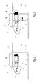
- Figures 2 and 3 illustrate, on a larger scale and a different angle to figure 1, the anti-wear element 12 placed immediately behind the front wheel 6.
- the other anti-wear elements 11, 13 and 14 are in every way identical to that, 12, which shall be described here.
- FIGSaid figures 2 and 3 show the body 2, illustrated schematically, as well as the front wheel 6.
- the body forms a shoulder 2', next to which is placed the anti-wear element 12.
- the latter consists of a flange suitable to rub against a platform 16.
- the anti-wear element is made of a material that is appropriate in view of said rubbing, so that it can take the place of the tyre on the wheel 6.
- a material that is appropriate in view of said rubbing, so that it can take the place of the tyre on the wheel 6.
- rubber in particular.
- the anti-wear element 12 is joined to the lower part of the body by means of an exterior bellows 18. Furthermore, a pre-stressed compression spring 12 joins the body and the anti-wear element 12, being suitable to push it against the platform in a horizontal direction.
- a pneumatic element 22 of a known type is suitable to compress the spring 20, so as to prevent it from pushing the anti-wear element 12.
- This pneumatic element 22 is connected to an energy source 24, belonging to the vehicle, which is for example an air compressor driven by the vehicle's diesel engine.
- an energy source 24 belonging to the vehicle, which is for example an air compressor driven by the vehicle's diesel engine.
- the pneumatic element 22, as well as the energy source 24 to which it is connected can be of a type other than pneumatic, in particular electric or hydraulic.
- the anti-wear element 12 When the vehicle is travelling normally between two stops, the anti-wear element 12 is retracted with respect to the wheel 6, that is to say that it is retracted from the side 6' of the tyre on said wheel 6. To this end, the pneumatic element 22 compresses the spring 20, which thus becomes shorter and does not therefore push the anti-wear element 12 to the other side of the body 2 (figure 2).
- the anti-wear element does not exceed the overall width of the vehicle. In such conditions, it is not likely to cause any disturbance to its outside environment, particularly to pedestrians or cyclists.
Landscapes
- Engineering & Computer Science (AREA)
- Mechanical Engineering (AREA)
- Chemical & Material Sciences (AREA)
- Combustion & Propulsion (AREA)
- Transportation (AREA)
- Platform Screen Doors And Railroad Systems (AREA)
- Tires In General (AREA)
- Current-Collector Devices For Electrically Propelled Vehicles (AREA)
- Motorcycle And Bicycle Frame (AREA)
- Handcart (AREA)
Abstract
Description
- The present invention concerns a transport vehicle having wheels with tyres.
- The invention is aimed at all types of transport vehicle whose route involves at least one station stop, during which people are likely to board the vehicle, and also to alight from it. It is aimed at such a vehicle, which may or may not be driven in a dedicated lane, in particular by means of electric wires, of rails or even by optic means.
- This type of transport vehicle typically includes a chassis mounted on at least one axle, which supports wheels having rubber tyres. In these conditions, transport vehicles in the sense of the invention include in particular, but not exclusively, buses and also trolleybuses.
- This having been specified, the invention aims to propose a transport vehicle which permits shorter boarding and alighting times for the passengers at the stop, while guaranteeing that the sides of the wheels are protected.
- To this end, it has as its object a transport vehicle, in particular a bus or a trolleybus, which includes a body, resting on at least one axle that is connected to wheels fitted with tyres, characterised in that the vehicle has at least one anti-wear element, moving laterally with respect to the body, between a retracted position in which it is retracted with respect to one side of the aforesaid tyre, and an open position, in which it protrudes laterally alongside the side of the tyre, in such a way as to rub against an edging, such as a platform, thus reducing the wear on said side of the tyre.
- According to other characteristics of the invention:
- it includes first means of movement, suitable to move the anti-wear element from its retracted position to its open position, as well as a second means of movement, suitable to move the anti-wear element from its open position to its retracted position;
- the first means of movement are spring mechanisms, while the second means of movement comprise a device to compress said spring mechanism;
- the compression device is connected to an energy source that is part of the vehicle, in particular of a pneumatic, electric or hydraulic nature;
- the anti-wear element is joined to the body by means of a bellows;
- the anti-wear element extends in a longitudinal direction, in the lower part of the body;
- four anti-wear elements are provided for, to be placed on both sides of each wheel.
- The invention will be better understood and other advantages of said invention will become clearer in the light of the following description of a method of implementation of a transport vehicle according to its principle, given purely by way of example and with reference to the annexed drawings, in which:
- figure 1 is a side view, illustrating a transport vehicle corresponding to the invention; and
- figures 2 and 3 are front views, illustrating on a larger scale two positions of an anti-wear element fitted onto the vehicle in figure 1.
- The transport vehicle illustrated in figure 1, which is a bus or a trolleybus, includes in a known manner a
body 2, which is fitted onto a front axle 4, as well as arear axle 5. These twoaxles 4 and 5 are equipped with wheels, numbered 6 and 7 respectively. Typically, it also has afront door 8, as well as arear door 10. - Four
anti-wear elements wheel 6 and 7, on the side of the vehicle. Said anti-wear elements, which extend longitudinally, shall be described in more detail below. - Figures 2 and 3 illustrate, on a larger scale and a different angle to figure 1, the
anti-wear element 12 placed immediately behind thefront wheel 6. However, the otheranti-wear elements - Said figures 2 and 3 show the
body 2, illustrated schematically, as well as thefront wheel 6. The body forms a shoulder 2', next to which is placed theanti-wear element 12. The latter consists of a flange suitable to rub against aplatform 16. - In these conditions, the anti-wear element is made of a material that is appropriate in view of said rubbing, so that it can take the place of the tyre on the
wheel 6. By way of a non-limitative example of such a material, we mention rubber in particular. - The
anti-wear element 12 is joined to the lower part of the body by means of anexterior bellows 18. Furthermore, apre-stressed compression spring 12 joins the body and theanti-wear element 12, being suitable to push it against the platform in a horizontal direction. - Finally, a
pneumatic element 22 of a known type, is suitable to compress thespring 20, so as to prevent it from pushing theanti-wear element 12. Thispneumatic element 22 is connected to anenergy source 24, belonging to the vehicle, which is for example an air compressor driven by the vehicle's diesel engine. As a variation, not that thepneumatic element 22, as well as theenergy source 24 to which it is connected, can be of a type other than pneumatic, in particular electric or hydraulic. - The use of the
anti-wear element 12, as described above, shall now be illustrated. - When the vehicle is travelling normally between two stops, the
anti-wear element 12 is retracted with respect to thewheel 6, that is to say that it is retracted from the side 6' of the tyre on saidwheel 6. To this end, thepneumatic element 22 compresses thespring 20, which thus becomes shorter and does not therefore push theanti-wear element 12 to the other side of the body 2 (figure 2). - Upon approaching the
platform 16, thepneumatic element 22 must be deactivated, so that it no longer compresses thespring 20. The latter then lengthens so as to push theanti-wear element 12 in the direction of saidplatform 16. This movement, illustrated in figure 3, is represented by arrow F. - Consequently, if the vehicle moves closer to the side of the platform, the latter comes into contact with the
anti-wear element 12, which rubs against the platform so that the anti-wear element substitutes the tyre. In other words, the rubbing of theanti-wear element 12 against theplatform 16 replaces that endured, in the state of the art, by the side 6' of the tyre against said platform. - Thanks to this invention, we can therefore see that it is possible for the vehicle to approach the platform at close distance without, however, damaging its tyres. Consequently, given that the distance between the vehicle and the platform is small, this guarantees that a particularly short time is needed for passengers to board and alight, while preserving the mechanical integrity of the tyre.
- Finally, note that, in its retracted position, the anti-wear element does not exceed the overall width of the vehicle. In such conditions, it is not likely to cause any disturbance to its outside environment, particularly to pedestrians or cyclists.
Claims (7)
- Transport vehicle, in particular a bus or trolleybus, comprising a vehicle body (2) resting on at least one axle (4, 5) joined to wheels (6, 7) fitted with tyres, characterised in that said vehicle has at least one anti-wear element (11, 12, 13, 14), moving laterally with respect to the body (2) between a retracted position (figure 2) in which it is retracted with respect to a side (6') of said tyre, and an open position (figure 3), in which it protrudes laterally with respect to said side (6') so that it rubs against an edge such as a platform (16) thus reducing the wear on this side (6') of the tyre.
- Transport vehicle according to claim 1, characterised in that it comprises a first means of movement (20), suitable for moving the anti-wear element (12) from its retracted position towards its open position, as well as a second means of movement (22) suitable to move the anti-wear element (12) from its open position to its retracted position.
- Transport vehicle according to claim 2, characterised in that the first means of movement are spring mechanisms (20), whereas the second means of movement include a compression device (22) for said spring mechanisms (20).
- Transport vehicle according to claim 3, characterised in that the compression device (22) is connected to an energy source (24) belonging to the vehicle, in particular of pneumatic, electric or hydraulic nature.
- Transport vehicle according to any one of the previous claims, characterised in that the anti-wear element (12) is joined to the body (2) by means of a bellows (18).
- Transport vehicle according to any one of the previous claims, characterised in that the anti-wear element extends in a longitudinal direction, in the lower part of the vehicle body (2).
- Transport vehicle according to claim 6, characterised in that there are four anti-wear elements (11, 12, 13, 14), arranged on either side of each wheel (6, 7).
Applications Claiming Priority (1)
| Application Number | Priority Date | Filing Date | Title |
|---|---|---|---|
| FR0511759A FR2893572B1 (en) | 2005-11-21 | 2005-11-21 | TRANSPORT VEHICLE COMPRISING PNEUMATIC WHEELS |
Publications (2)
| Publication Number | Publication Date |
|---|---|
| EP1787885A1 true EP1787885A1 (en) | 2007-05-23 |
| EP1787885B1 EP1787885B1 (en) | 2009-04-01 |
Family
ID=36001123
Family Applications (1)
| Application Number | Title | Priority Date | Filing Date |
|---|---|---|---|
| EP06124450A Not-in-force EP1787885B1 (en) | 2005-11-21 | 2006-11-21 | Transport vehicle having wheels with tyres |
Country Status (5)
| Country | Link |
|---|---|
| EP (1) | EP1787885B1 (en) |
| AT (1) | ATE427246T1 (en) |
| DE (1) | DE602006006003D1 (en) |
| ES (1) | ES2323891T3 (en) |
| FR (1) | FR2893572B1 (en) |
Cited By (1)
| Publication number | Priority date | Publication date | Assignee | Title |
|---|---|---|---|---|
| EP2090473A1 (en) * | 2008-02-15 | 2009-08-19 | Diana Graf | Ramming protection device for a motor vehicle |
Citations (4)
| Publication number | Priority date | Publication date | Assignee | Title |
|---|---|---|---|---|
| FR2311699A1 (en) * | 1975-05-19 | 1976-12-17 | Nissan Motor | TRANSPORT VEHICLE CAPABLE OF FOLLOWING GUIDANCE TRACKS AND BEING MANUAL DIRECTED |
| DE2636656A1 (en) * | 1976-08-14 | 1978-02-16 | Daimler Benz Ag | Road or track adaptable urban transport system - has retractable system guide rollers on ends of arms attached to non-resilient parts of vehicle axles |
| US4445440A (en) * | 1981-01-23 | 1984-05-01 | Daimler-Benz Aktiengesellschaft | Track guided vehicle |
| DE3405872A1 (en) * | 1984-02-18 | 1985-08-22 | Daimler-Benz Ag, 7000 Stuttgart | CROSS-GUIDED DEVICE FOR TRACKED-INSERTED VEHICLES |
Family Cites Families (1)
| Publication number | Priority date | Publication date | Assignee | Title |
|---|---|---|---|---|
| DE4123948C2 (en) * | 1991-07-19 | 1995-01-19 | Bayerische Motoren Werke Ag | Motor vehicle with a side protection device |
-
2005
- 2005-11-21 FR FR0511759A patent/FR2893572B1/en not_active Expired - Fee Related
-
2006
- 2006-11-21 AT AT06124450T patent/ATE427246T1/en not_active IP Right Cessation
- 2006-11-21 DE DE602006006003T patent/DE602006006003D1/en active Active
- 2006-11-21 ES ES06124450T patent/ES2323891T3/en active Active
- 2006-11-21 EP EP06124450A patent/EP1787885B1/en not_active Not-in-force
Patent Citations (4)
| Publication number | Priority date | Publication date | Assignee | Title |
|---|---|---|---|---|
| FR2311699A1 (en) * | 1975-05-19 | 1976-12-17 | Nissan Motor | TRANSPORT VEHICLE CAPABLE OF FOLLOWING GUIDANCE TRACKS AND BEING MANUAL DIRECTED |
| DE2636656A1 (en) * | 1976-08-14 | 1978-02-16 | Daimler Benz Ag | Road or track adaptable urban transport system - has retractable system guide rollers on ends of arms attached to non-resilient parts of vehicle axles |
| US4445440A (en) * | 1981-01-23 | 1984-05-01 | Daimler-Benz Aktiengesellschaft | Track guided vehicle |
| DE3405872A1 (en) * | 1984-02-18 | 1985-08-22 | Daimler-Benz Ag, 7000 Stuttgart | CROSS-GUIDED DEVICE FOR TRACKED-INSERTED VEHICLES |
Cited By (1)
| Publication number | Priority date | Publication date | Assignee | Title |
|---|---|---|---|---|
| EP2090473A1 (en) * | 2008-02-15 | 2009-08-19 | Diana Graf | Ramming protection device for a motor vehicle |
Also Published As
| Publication number | Publication date |
|---|---|
| FR2893572B1 (en) | 2010-03-05 |
| FR2893572A1 (en) | 2007-05-25 |
| ATE427246T1 (en) | 2009-04-15 |
| EP1787885B1 (en) | 2009-04-01 |
| ES2323891T3 (en) | 2009-07-27 |
| DE602006006003D1 (en) | 2009-05-14 |
Similar Documents
| Publication | Publication Date | Title |
|---|---|---|
| KR101848798B1 (en) | System for transporting people | |
| US9067617B2 (en) | Wheel turn initiator | |
| US20110123309A1 (en) | Replacement station for the traction batteries of electric vehicles | |
| AU633818B2 (en) | An electromagnetic suspension and propulsion system for a vehicle | |
| CN121246738A (en) | Conveyor and automatic parking system for mobile four-wheeled vehicle | |
| US10471914B2 (en) | Deployable debris protection device for an automotive vehicle | |
| GB2497827A (en) | Vehicle for receiving inductively coupled power having a power pickup arrangement pivotally attached to the vehicle | |
| CA2973308C (en) | Vehicle safety guard | |
| CN110077433A (en) | Trolleybus | |
| JP2016049936A (en) | Snow removal device, vehicle, and track-based traffic system | |
| EP1787885B1 (en) | Transport vehicle having wheels with tyres | |
| US20140261066A1 (en) | Retractable Rail Wheels for a Road/Rail Vehicle | |
| EP1859996A1 (en) | Transport vehicle equipped with access device for persons with reduced mobility | |
| US20040173992A1 (en) | Truck slide assembly | |
| EP1826063B1 (en) | Transport vehicle equipped with access device for persons with reduced mobility | |
| US10252752B2 (en) | Splash-protection device for a wheel-mounted vehicle, and assembly having such device | |
| FR1454879A (en) | Conveyor device for motor vehicle assembly operations | |
| EP1561674B1 (en) | Adjustable-wheelbase vehicle chassis | |
| AU2020343394B2 (en) | Protective device for rail vehicle | |
| KR102272221B1 (en) | a guided wheel device for a mini tram | |
| EP1731401B1 (en) | Transport vehicle having wheels with tyres | |
| RU35612U1 (en) | CAR AND RAIL VEHICLE | |
| WO2020212733A1 (en) | Anti-turbulence system for industrial vehicles | |
| DE4042381A1 (en) | Transportation unit for workpieces - uses on-board sensors to detect pressure of obstruction and prevent damage | |
| ITMI20061820A1 (en) | CONTROL SYSTEM AND MANAGEMENT OF INFLATION AND DEFLATING ACTIONS OF SPEILER GONGIABILI FOR INDUSTRIAL VEHICLE |
Legal Events
| Date | Code | Title | Description |
|---|---|---|---|
| PUAI | Public reference made under article 153(3) epc to a published international application that has entered the european phase |
Free format text: ORIGINAL CODE: 0009012 |
|
| AK | Designated contracting states |
Kind code of ref document: A1 Designated state(s): AT BE BG CH CY CZ DE DK EE ES FI FR GB GR HU IE IS IT LI LT LU LV MC NL PL PT RO SE SI SK TR |
|
| AX | Request for extension of the european patent |
Extension state: AL BA HR MK YU |
|
| 17P | Request for examination filed |
Effective date: 20071121 |
|
| 17Q | First examination report despatched |
Effective date: 20071220 |
|
| AKX | Designation fees paid |
Designated state(s): AT BE BG CH CY CZ DE DK EE ES FI FR GB GR HU IE IS IT LI LT LU LV MC NL PL PT RO SE SI SK TR |
|
| RIC1 | Information provided on ipc code assigned before grant |
Ipc: B60R 19/38 20060101AFI20080730BHEP |
|
| GRAP | Despatch of communication of intention to grant a patent |
Free format text: ORIGINAL CODE: EPIDOSNIGR1 |
|
| GRAS | Grant fee paid |
Free format text: ORIGINAL CODE: EPIDOSNIGR3 |
|
| GRAA | (expected) grant |
Free format text: ORIGINAL CODE: 0009210 |
|
| AK | Designated contracting states |
Kind code of ref document: B1 Designated state(s): AT BE BG CH CY CZ DE DK EE ES FI FR GB GR HU IE IS IT LI LT LU LV MC NL PL PT RO SE SI SK TR |
|
| REG | Reference to a national code |
Ref country code: GB Ref legal event code: FG4D |
|
| REG | Reference to a national code |
Ref country code: CH Ref legal event code: EP |
|
| REG | Reference to a national code |
Ref country code: IE Ref legal event code: FG4D |
|
| REF | Corresponds to: |
Ref document number: 602006006003 Country of ref document: DE Date of ref document: 20090514 Kind code of ref document: P |
|
| REG | Reference to a national code |
Ref country code: SE Ref legal event code: TRGR |
|
| REG | Reference to a national code |
Ref country code: ES Ref legal event code: FG2A Ref document number: 2323891 Country of ref document: ES Kind code of ref document: T3 |
|
| PG25 | Lapsed in a contracting state [announced via postgrant information from national office to epo] |
Ref country code: SI Free format text: LAPSE BECAUSE OF FAILURE TO SUBMIT A TRANSLATION OF THE DESCRIPTION OR TO PAY THE FEE WITHIN THE PRESCRIBED TIME-LIMIT Effective date: 20090401 |
|
| PG25 | Lapsed in a contracting state [announced via postgrant information from national office to epo] |
Ref country code: PT Free format text: LAPSE BECAUSE OF FAILURE TO SUBMIT A TRANSLATION OF THE DESCRIPTION OR TO PAY THE FEE WITHIN THE PRESCRIBED TIME-LIMIT Effective date: 20090902 Ref country code: AT Free format text: LAPSE BECAUSE OF FAILURE TO SUBMIT A TRANSLATION OF THE DESCRIPTION OR TO PAY THE FEE WITHIN THE PRESCRIBED TIME-LIMIT Effective date: 20090401 Ref country code: EE Free format text: LAPSE BECAUSE OF FAILURE TO SUBMIT A TRANSLATION OF THE DESCRIPTION OR TO PAY THE FEE WITHIN THE PRESCRIBED TIME-LIMIT Effective date: 20090401 Ref country code: LT Free format text: LAPSE BECAUSE OF FAILURE TO SUBMIT A TRANSLATION OF THE DESCRIPTION OR TO PAY THE FEE WITHIN THE PRESCRIBED TIME-LIMIT Effective date: 20090401 Ref country code: FI Free format text: LAPSE BECAUSE OF FAILURE TO SUBMIT A TRANSLATION OF THE DESCRIPTION OR TO PAY THE FEE WITHIN THE PRESCRIBED TIME-LIMIT Effective date: 20090401 |
|
| PG25 | Lapsed in a contracting state [announced via postgrant information from national office to epo] |
Ref country code: IS Free format text: LAPSE BECAUSE OF FAILURE TO SUBMIT A TRANSLATION OF THE DESCRIPTION OR TO PAY THE FEE WITHIN THE PRESCRIBED TIME-LIMIT Effective date: 20090801 Ref country code: LV Free format text: LAPSE BECAUSE OF FAILURE TO SUBMIT A TRANSLATION OF THE DESCRIPTION OR TO PAY THE FEE WITHIN THE PRESCRIBED TIME-LIMIT Effective date: 20090401 Ref country code: PL Free format text: LAPSE BECAUSE OF FAILURE TO SUBMIT A TRANSLATION OF THE DESCRIPTION OR TO PAY THE FEE WITHIN THE PRESCRIBED TIME-LIMIT Effective date: 20090401 |
|
| PG25 | Lapsed in a contracting state [announced via postgrant information from national office to epo] |
Ref country code: CZ Free format text: LAPSE BECAUSE OF FAILURE TO SUBMIT A TRANSLATION OF THE DESCRIPTION OR TO PAY THE FEE WITHIN THE PRESCRIBED TIME-LIMIT Effective date: 20090401 Ref country code: RO Free format text: LAPSE BECAUSE OF FAILURE TO SUBMIT A TRANSLATION OF THE DESCRIPTION OR TO PAY THE FEE WITHIN THE PRESCRIBED TIME-LIMIT Effective date: 20090401 Ref country code: DK Free format text: LAPSE BECAUSE OF FAILURE TO SUBMIT A TRANSLATION OF THE DESCRIPTION OR TO PAY THE FEE WITHIN THE PRESCRIBED TIME-LIMIT Effective date: 20090401 |
|
| PLBE | No opposition filed within time limit |
Free format text: ORIGINAL CODE: 0009261 |
|
| STAA | Information on the status of an ep patent application or granted ep patent |
Free format text: STATUS: NO OPPOSITION FILED WITHIN TIME LIMIT |
|
| PG25 | Lapsed in a contracting state [announced via postgrant information from national office to epo] |
Ref country code: SK Free format text: LAPSE BECAUSE OF FAILURE TO SUBMIT A TRANSLATION OF THE DESCRIPTION OR TO PAY THE FEE WITHIN THE PRESCRIBED TIME-LIMIT Effective date: 20090401 Ref country code: BE Free format text: LAPSE BECAUSE OF FAILURE TO SUBMIT A TRANSLATION OF THE DESCRIPTION OR TO PAY THE FEE WITHIN THE PRESCRIBED TIME-LIMIT Effective date: 20090401 |
|
| 26N | No opposition filed |
Effective date: 20100105 |
|
| PG25 | Lapsed in a contracting state [announced via postgrant information from national office to epo] |
Ref country code: BG Free format text: LAPSE BECAUSE OF FAILURE TO SUBMIT A TRANSLATION OF THE DESCRIPTION OR TO PAY THE FEE WITHIN THE PRESCRIBED TIME-LIMIT Effective date: 20090701 |
|
| PG25 | Lapsed in a contracting state [announced via postgrant information from national office to epo] |
Ref country code: MC Free format text: LAPSE BECAUSE OF NON-PAYMENT OF DUE FEES Effective date: 20091130 |
|
| REG | Reference to a national code |
Ref country code: IE Ref legal event code: MM4A |
|
| PG25 | Lapsed in a contracting state [announced via postgrant information from national office to epo] |
Ref country code: IE Free format text: LAPSE BECAUSE OF NON-PAYMENT OF DUE FEES Effective date: 20091121 Ref country code: GR Free format text: LAPSE BECAUSE OF FAILURE TO SUBMIT A TRANSLATION OF THE DESCRIPTION OR TO PAY THE FEE WITHIN THE PRESCRIBED TIME-LIMIT Effective date: 20090702 |
|
| PG25 | Lapsed in a contracting state [announced via postgrant information from national office to epo] |
Ref country code: IT Free format text: LAPSE BECAUSE OF NON-PAYMENT OF DUE FEES Effective date: 20091121 |
|
| PG25 | Lapsed in a contracting state [announced via postgrant information from national office to epo] |
Ref country code: LU Free format text: LAPSE BECAUSE OF NON-PAYMENT OF DUE FEES Effective date: 20091121 |
|
| PG25 | Lapsed in a contracting state [announced via postgrant information from national office to epo] |
Ref country code: HU Free format text: LAPSE BECAUSE OF FAILURE TO SUBMIT A TRANSLATION OF THE DESCRIPTION OR TO PAY THE FEE WITHIN THE PRESCRIBED TIME-LIMIT Effective date: 20091002 |
|
| REG | Reference to a national code |
Ref country code: CH Ref legal event code: PL |
|
| PG25 | Lapsed in a contracting state [announced via postgrant information from national office to epo] |
Ref country code: CH Free format text: LAPSE BECAUSE OF NON-PAYMENT OF DUE FEES Effective date: 20101130 Ref country code: LI Free format text: LAPSE BECAUSE OF NON-PAYMENT OF DUE FEES Effective date: 20101130 |
|
| PGRI | Patent reinstated in contracting state [announced from national office to epo] |
Ref country code: IT Effective date: 20110616 |
|
| PG25 | Lapsed in a contracting state [announced via postgrant information from national office to epo] |
Ref country code: TR Free format text: LAPSE BECAUSE OF FAILURE TO SUBMIT A TRANSLATION OF THE DESCRIPTION OR TO PAY THE FEE WITHIN THE PRESCRIBED TIME-LIMIT Effective date: 20090401 |
|
| PG25 | Lapsed in a contracting state [announced via postgrant information from national office to epo] |
Ref country code: CY Free format text: LAPSE BECAUSE OF FAILURE TO SUBMIT A TRANSLATION OF THE DESCRIPTION OR TO PAY THE FEE WITHIN THE PRESCRIBED TIME-LIMIT Effective date: 20090401 |
|
| PGFP | Annual fee paid to national office [announced via postgrant information from national office to epo] |
Ref country code: ES Payment date: 20141013 Year of fee payment: 9 Ref country code: SE Payment date: 20141111 Year of fee payment: 9 Ref country code: FR Payment date: 20141110 Year of fee payment: 9 Ref country code: GB Payment date: 20141119 Year of fee payment: 9 Ref country code: DE Payment date: 20141118 Year of fee payment: 9 |
|
| PGFP | Annual fee paid to national office [announced via postgrant information from national office to epo] |
Ref country code: NL Payment date: 20141108 Year of fee payment: 9 |
|
| PGFP | Annual fee paid to national office [announced via postgrant information from national office to epo] |
Ref country code: IT Payment date: 20141031 Year of fee payment: 9 |
|
| REG | Reference to a national code |
Ref country code: DE Ref legal event code: R119 Ref document number: 602006006003 Country of ref document: DE |
|
| GBPC | Gb: european patent ceased through non-payment of renewal fee |
Effective date: 20151121 |
|
| PG25 | Lapsed in a contracting state [announced via postgrant information from national office to epo] |
Ref country code: IT Free format text: LAPSE BECAUSE OF NON-PAYMENT OF DUE FEES Effective date: 20151121 |
|
| REG | Reference to a national code |
Ref country code: NL Ref legal event code: MM Effective date: 20151201 |
|
| REG | Reference to a national code |
Ref country code: FR Ref legal event code: ST Effective date: 20160729 |
|
| PG25 | Lapsed in a contracting state [announced via postgrant information from national office to epo] |
Ref country code: SE Free format text: LAPSE BECAUSE OF NON-PAYMENT OF DUE FEES Effective date: 20151122 |
|
| PG25 | Lapsed in a contracting state [announced via postgrant information from national office to epo] |
Ref country code: NL Free format text: LAPSE BECAUSE OF NON-PAYMENT OF DUE FEES Effective date: 20151201 |
|
| PG25 | Lapsed in a contracting state [announced via postgrant information from national office to epo] |
Ref country code: DE Free format text: LAPSE BECAUSE OF NON-PAYMENT OF DUE FEES Effective date: 20160601 Ref country code: GB Free format text: LAPSE BECAUSE OF NON-PAYMENT OF DUE FEES Effective date: 20151121 |
|
| PG25 | Lapsed in a contracting state [announced via postgrant information from national office to epo] |
Ref country code: FR Free format text: LAPSE BECAUSE OF NON-PAYMENT OF DUE FEES Effective date: 20151130 |
|
| PG25 | Lapsed in a contracting state [announced via postgrant information from national office to epo] |
Ref country code: ES Free format text: LAPSE BECAUSE OF NON-PAYMENT OF DUE FEES Effective date: 20151122 |
|
| REG | Reference to a national code |
Ref country code: CH Ref legal event code: PK Free format text: DER EINTRAG 'EINSPRUCH' ERFOLGTE IRRTUEMLICH |
|
| REG | Reference to a national code |
Ref country code: ES Ref legal event code: FD2A Effective date: 20180710 |