EP1787613A2 - Vehicle, device and process for accessing said vehicle by persons with reduced mobility. - Google Patents
Vehicle, device and process for accessing said vehicle by persons with reduced mobility. Download PDFInfo
- Publication number
- EP1787613A2 EP1787613A2 EP06124449A EP06124449A EP1787613A2 EP 1787613 A2 EP1787613 A2 EP 1787613A2 EP 06124449 A EP06124449 A EP 06124449A EP 06124449 A EP06124449 A EP 06124449A EP 1787613 A2 EP1787613 A2 EP 1787613A2
- Authority
- EP
- European Patent Office
- Prior art keywords
- vehicle
- height
- floor
- platform
- distance
- Prior art date
- Legal status (The legal status is an assumption and is not a legal conclusion. Google has not performed a legal analysis and makes no representation as to the accuracy of the status listed.)
- Granted
Links
Images


Classifications
-
- A—HUMAN NECESSITIES
- A61—MEDICAL OR VETERINARY SCIENCE; HYGIENE
- A61G—TRANSPORT, PERSONAL CONVEYANCES, OR ACCOMMODATION SPECIALLY ADAPTED FOR PATIENTS OR DISABLED PERSONS; OPERATING TABLES OR CHAIRS; CHAIRS FOR DENTISTRY; FUNERAL DEVICES
- A61G3/00—Ambulance aspects of vehicles; Vehicles with special provisions for transporting patients or disabled persons, or their personal conveyances, e.g. for facilitating access of, or for loading, wheelchairs
- A61G3/02—Loading or unloading personal conveyances; Facilitating access of patients or disabled persons to, or exit from, vehicles
- A61G3/06—Transfer using ramps, lifts or the like
- A61G3/061—Transfer using ramps, lifts or the like using ramps
-
- A—HUMAN NECESSITIES
- A61—MEDICAL OR VETERINARY SCIENCE; HYGIENE
- A61G—TRANSPORT, PERSONAL CONVEYANCES, OR ACCOMMODATION SPECIALLY ADAPTED FOR PATIENTS OR DISABLED PERSONS; OPERATING TABLES OR CHAIRS; CHAIRS FOR DENTISTRY; FUNERAL DEVICES
- A61G3/00—Ambulance aspects of vehicles; Vehicles with special provisions for transporting patients or disabled persons, or their personal conveyances, e.g. for facilitating access of, or for loading, wheelchairs
- A61G3/02—Loading or unloading personal conveyances; Facilitating access of patients or disabled persons to, or exit from, vehicles
- A61G3/06—Transfer using ramps, lifts or the like
- A61G3/065—Transfer using ramps, lifts or the like using an adjustable suspension lowering device for the whole vehicle
-
- A—HUMAN NECESSITIES
- A61—MEDICAL OR VETERINARY SCIENCE; HYGIENE
- A61G—TRANSPORT, PERSONAL CONVEYANCES, OR ACCOMMODATION SPECIALLY ADAPTED FOR PATIENTS OR DISABLED PERSONS; OPERATING TABLES OR CHAIRS; CHAIRS FOR DENTISTRY; FUNERAL DEVICES
- A61G3/00—Ambulance aspects of vehicles; Vehicles with special provisions for transporting patients or disabled persons, or their personal conveyances, e.g. for facilitating access of, or for loading, wheelchairs
- A61G3/02—Loading or unloading personal conveyances; Facilitating access of patients or disabled persons to, or exit from, vehicles
- A61G3/06—Transfer using ramps, lifts or the like
- A61G3/067—Transfer using ramps, lifts or the like with compartment for horizontally storing the ramp or lift
-
- B—PERFORMING OPERATIONS; TRANSPORTING
- B60—VEHICLES IN GENERAL
- B60G—VEHICLE SUSPENSION ARRANGEMENTS
- B60G17/00—Resilient suspensions having means for adjusting the spring or vibration-damper characteristics, for regulating the distance between a supporting surface and a sprung part of vehicle or for locking suspension during use to meet varying vehicular or surface conditions, e.g. due to speed or load
- B60G17/015—Resilient suspensions having means for adjusting the spring or vibration-damper characteristics, for regulating the distance between a supporting surface and a sprung part of vehicle or for locking suspension during use to meet varying vehicular or surface conditions, e.g. due to speed or load the regulating means comprising electric or electronic elements
- B60G17/017—Resilient suspensions having means for adjusting the spring or vibration-damper characteristics, for regulating the distance between a supporting surface and a sprung part of vehicle or for locking suspension during use to meet varying vehicular or surface conditions, e.g. due to speed or load the regulating means comprising electric or electronic elements characterised by their use when the vehicle is stationary, e.g. during loading, engine start-up or switch-off
-
- B—PERFORMING OPERATIONS; TRANSPORTING
- B60—VEHICLES IN GENERAL
- B60G—VEHICLE SUSPENSION ARRANGEMENTS
- B60G17/00—Resilient suspensions having means for adjusting the spring or vibration-damper characteristics, for regulating the distance between a supporting surface and a sprung part of vehicle or for locking suspension during use to meet varying vehicular or surface conditions, e.g. due to speed or load
- B60G17/015—Resilient suspensions having means for adjusting the spring or vibration-damper characteristics, for regulating the distance between a supporting surface and a sprung part of vehicle or for locking suspension during use to meet varying vehicular or surface conditions, e.g. due to speed or load the regulating means comprising electric or electronic elements
- B60G17/019—Resilient suspensions having means for adjusting the spring or vibration-damper characteristics, for regulating the distance between a supporting surface and a sprung part of vehicle or for locking suspension during use to meet varying vehicular or surface conditions, e.g. due to speed or load the regulating means comprising electric or electronic elements characterised by the type of sensor or the arrangement thereof
-
- B—PERFORMING OPERATIONS; TRANSPORTING
- B60—VEHICLES IN GENERAL
- B60P—VEHICLES ADAPTED FOR LOAD TRANSPORTATION OR TO TRANSPORT, TO CARRY, OR TO COMPRISE SPECIAL LOADS OR OBJECTS
- B60P1/00—Vehicles predominantly for transporting loads and modified to facilitate loading, consolidating the load, or unloading
- B60P1/43—Vehicles predominantly for transporting loads and modified to facilitate loading, consolidating the load, or unloading using a loading ramp mounted on the vehicle
-
- B—PERFORMING OPERATIONS; TRANSPORTING
- B60—VEHICLES IN GENERAL
- B60G—VEHICLE SUSPENSION ARRANGEMENTS
- B60G2300/00—Indexing codes relating to the type of vehicle
- B60G2300/14—Buses
-
- B—PERFORMING OPERATIONS; TRANSPORTING
- B60—VEHICLES IN GENERAL
- B60G—VEHICLE SUSPENSION ARRANGEMENTS
- B60G2300/00—Indexing codes relating to the type of vehicle
- B60G2300/34—Ambulances
-
- B—PERFORMING OPERATIONS; TRANSPORTING
- B60—VEHICLES IN GENERAL
- B60G—VEHICLE SUSPENSION ARRANGEMENTS
- B60G2300/00—Indexing codes relating to the type of vehicle
- B60G2300/38—Low or lowerable bed vehicles
-
- B—PERFORMING OPERATIONS; TRANSPORTING
- B60—VEHICLES IN GENERAL
- B60G—VEHICLE SUSPENSION ARRANGEMENTS
- B60G2400/00—Indexing codes relating to detected, measured or calculated conditions or factors
- B60G2400/80—Exterior conditions
-
- B—PERFORMING OPERATIONS; TRANSPORTING
- B60—VEHICLES IN GENERAL
- B60G—VEHICLE SUSPENSION ARRANGEMENTS
- B60G2400/00—Indexing codes relating to detected, measured or calculated conditions or factors
- B60G2400/80—Exterior conditions
- B60G2400/82—Ground surface
- B60G2400/823—Obstacle sensing
-
- B—PERFORMING OPERATIONS; TRANSPORTING
- B60—VEHICLES IN GENERAL
- B60G—VEHICLE SUSPENSION ARRANGEMENTS
- B60G2500/00—Indexing codes relating to the regulated action or device
- B60G2500/30—Height or ground clearance
-
- B—PERFORMING OPERATIONS; TRANSPORTING
- B60—VEHICLES IN GENERAL
- B60G—VEHICLE SUSPENSION ARRANGEMENTS
- B60G2800/00—Indexing codes relating to the type of movement or to the condition of the vehicle and to the end result to be achieved by the control action
- B60G2800/20—Stationary vehicle
- B60G2800/202—Stationary vehicle kneeling, e.g. for letting passengers on/off
-
- B—PERFORMING OPERATIONS; TRANSPORTING
- B60—VEHICLES IN GENERAL
- B60G—VEHICLE SUSPENSION ARRANGEMENTS
- B60G2800/00—Indexing codes relating to the type of movement or to the condition of the vehicle and to the end result to be achieved by the control action
- B60G2800/20—Stationary vehicle
- B60G2800/203—Stationary vehicle lowering the floor for loading/unloading
-
- B—PERFORMING OPERATIONS; TRANSPORTING
- B60—VEHICLES IN GENERAL
- B60G—VEHICLE SUSPENSION ARRANGEMENTS
- B60G2800/00—Indexing codes relating to the type of movement or to the condition of the vehicle and to the end result to be achieved by the control action
- B60G2800/20—Stationary vehicle
- B60G2800/204—Stationary vehicle adjusting floor height to the loading ramp level
Definitions
- the present invention concerns a vehicle, a device and a process for accessing the vehicle by persons with reduced mobility.
- the access device also has an internal mechanism to allow the access ramp to be opened out onto platforms of different heights. This is necessary as the heights of the platforms vary from one place to the next.
- a platform is, for example, a pavement.
- the present invention aims to provide a solution to this inconvenience by proposing a vehicle equipped with a more simple access device.
- the object of the invention is therefore a transport vehicle for persons with reduced mobility, equipped with an access device to the vehicle for said persons with reduced mobility, having a control unit able to automatically guide the mechanism which adjusts the height of the vehicle floor depending on the height of the platform in a direction perpendicular to the rolling surface of the vehicle.
- the adjustment of the height of the vehicle floor with respect to the height of the docking surface allows the access device to be adapted to different heights of platform, without it being necessary to resort to an internal mechanism in the device to achieve said adjustment.
- the access device can be simplified or its range of operation can be extended.
- a further object of the invention is the access device employed in the aforesaid vehicle.
- a further object of the invention is a process for accessing a transport vehicle for persons with reduced mobility, with the help of the aforesaid access device, this process comprising:
- persons with reduced mobility are in particular meant persons in a wheelchair or persons who have difficulty boarding a vehicle such as a bus.
- Figure 1 is a schematic representation of the vertical cross-section of the structure of a vehicle 2 equipped with a device 4 for accessing said vehicle for persons with reduced mobility.
- the plane of the cross-section is perpendicular to the direction of movement of the vehicle 2.
- vehicle 2 is a public transport vehicle such as a bus.
- Vehicle 2 includes a body 6 equipped with a door 8 to allow passengers to board or alight vehicle 2. Said body 6 rests on a chassis 10.
- Vehicle 2 also includes a floor 12 designed to support passengers inside the vehicle 2.
- the floor 12 also rests on the chassis.
- the chassis 10 itself rests on the wheels of the vehicle 2 which rest on a rolling surface 16 on the ground.
- Surface 16 is, for example, the surface of a road or any traffic route.
- the mechanism 20 includes an inflatable suspension cushion 22 and a controllable compressor 24 suitable to regulate the pressure inside the cushion 22.
- a controllable compressor 24 suitable to regulate the pressure inside the cushion 22.
- the cushion 22 is shown as being located between the chassis 10 and an axle 28 of the wheel 18.
- the device 4 is equipped with an access ramp 30 that can be moved between an open position in which it reduces the space between the floor 12 and a docking surface 32, and a retracted position (shown in figure 1) inside vehicle 2.
- the surface 32 is the upper surface of an exterior platform 34 on which people with reduced mobility can move in order to board the vehicle 2 or, contrarily, to alight.
- Said surface 32 is situated at a height h T with respect to surface 16. Height h T is measured in a direction perpendicular to the surface 16.
- the ramp 30 can be moved between its open position and its retracted position by a controllable motor 38.
- Motor 38 is controlled by a control unit 40.
- the control unit 40 is able to receive a command to open out or on the contrary to retract, sent by the driver of vehicle 2.
- Device 4 also includes a sensor 42 to measure a distance c and a sensor 44 to measure a distance d fixed on the vehicle 2.
- Sensor 42 is able to measure distance c along a line of sight 46.
- the line of sight is inclined at an angle ⁇ with respect to the vertical of vehicle 2 in the cross-section drawing.
- P 1 designates a plane integral with vehicle 2 and parallel to the floor 12. Plane P 1 crosses the line of sight 46 at the level of the sensor 42.
- a plane P 2 is also designated, integral with the platform 34 and parallel to the docking surface 32. Planes P 1 and P 2 are, here, parallel to each other and separated by a distance h measured in a direction that is perpendicular to plane P 1 . To make the illustration clearer, the distance h has been exaggerated in figure 1.
- a plane P 3 parallel to the floor 12 is a median plane of the ramp 30.
- Sensor 44 measures the distance d along a line of sight 48.
- the line of sight 48 is parallel to plane P 1 , aligned in a direction perpendicular to the direction in which the vehicle 2 is travelling, and directed towards the platform 34.
- unit 40 is able to guide the mechanism 20 according to the distance h separating plane P 1 from plane P 2 , so as to adjust the height of the device 4 according to the height h T of the platform 34.
- unit 40 is able to control the compressor 24 to modify the pressure inside the inflatable cushion 22.
- Unit 40 also includes a memory containing the various thresholds and parameters necessary for it to work.
- Figure 2 shows in unbroken lines a view from above of the ramp 30 in its open position.
- a broken line 50 shows the limit of the vehicle body 6 vertically above the door 8
- a broken line 52 shows the limit of the surface 32 on which passengers board and alight.
- the dotted lines in figure 2 show the ramp 30 in its retracted position.
- Ramp 30 can only be opened in the plane P 3 around a vertical axis of rotation 54.
- the direction in which the ramp 30 opens is shown by an arrow on figure 2.
- the useful surface of the ramp 30 onto which people with reduced mobility move when they want to board or alight from the vehicle 2 is approximately rectangular.
- the width of this active surface L is between 60cm and 1.5m, preferably in the range of 60cm and 1cm.
- the depth P of this active surface is between 10 and 50cm and preferably in the range of 25 and 35cm.
- An obstacle detector 58 is provided for on the surface of the ramp 30 opposite the platform 34 in its open position.
- the sensor 44 measures the distance d .
- step 72 unit 40 checks that the distance d is less than a predetermined threshold S 1 . Should that not be the case, unit 40 prevents, in step 74, the opening of the ramp 30. Indeed, the opening of the ramp in this case would not be at all helpful for persons with reduced mobility, as this opening would not cover more than 95% of the distance between the edges 50 and 52.
- the senor 42 measures distance c and transmits it to unit 40.
- step 84 unit 40 checks that the measured distance h is comprised in a permissible operative range [S 2 ; S 3 ].
- step 86 unit 40 prevents ramp 30 from opening. Indeed, the difference in height between planes P 1 and P 2 is such that it is impossible to adjust the height h v of the vehicle floor so as to bring plane P 3 to the level of plane P 2 .
- step 88 unit 40 guides the mechanism 20 to adjust the height of the vehicle floor 12 according to the measured height h. More precisely, here unit 40 guides the mechanism 20 until plane P 3 meets plane P 2 or is distant from plane P 2 by a distance of less than 5cm, and preferably less then 2cm.
- step 90 the unit 40 orders the opening of the ramp 30.
- ramp 30 is opened from its retracted position to its open position.
- step 92 unit 40 constantly checks that the detector 58 has not detected any obstacles. If it has, unit 40 immediately interrupts the opening of the ramp 30, in step 94. If not, ramp 30 is opened to its fully open position.
- step 96 while the ramp 30 is in its open position, unit 40 regulates the height h v to maintain it constant.
- the weight of the vehicle 2 changes due to the fact that passengers are boarding and alighting from the vehicle, the height h v remains constant and plane P 3 remains at an acceptable distance from plane P 2 .
- Step 96 lasts until unit 40 orders, with step 98, the retraction of the access ramp.
- Step 98 is, for example, triggered by a command sent by the driver.
- Figure 4 shows another process for accessing the vehicle 2 with the help of the device 4. This process is identical to that in figure 3 with the exception of step 88, which is replaced by step 110 to adjust the height h v .
- step 100 when an operation 112 takes place, the sensor 42 measures the distance c(h v ).
- unit 40 guides the mechanism 20 to vertically move the line of sight 48 at a predetermined pitch ⁇ h. For example, unit 40 gradually lowers the height h v from a maximum height h v .
- the sensor 42 measures the new distance c (h v + ⁇ h) .
- unit 40 In operation 118, unit 40 once again lowers the line of sight 48 at pitch ⁇ h and, in operation 120, sensor 42 measures the distance c(h v +2 ⁇ h).
- unit 40 checks whether the second derivative dc 2 dh v 2 has reached an extreme.
- unit 40 compares the second derivative dc 2 dh v 2 to a predetermined threshold ⁇ . If the second dc 2 dh v 2 is less than the threshold ⁇ , steps 112 and 124 are repeated. If not, in operation 126 unit 40 guides the mechanism 20 to take plane P 3 to the level of plane P 2 , then step 110 stops and the process continues with steps 90 and 92. In operation 126, distance d is used to determine the lowering of the vehicle floor that will allow plane P 3 to be brought to the level of plane P 2 .
- Figure 5 shows the evolution of the distance c according to the height of the vehicle 2 in the specific case of the platform 34. More precisely, when the line of sight 46 points at the surface 32, each time the height h v is lowered by the pitch ⁇ h, distance c decreases. This is represented by a declining straight line 130 in figure 5. Distance c stops decreasing when the line of sight points at the vertical part of platform 34. This is represented by the straight line 132 parallel to the axis of the abscissas. The point where these straight lines 130 and 132 intersect is the position in which the line of sight 46 points at edge 52. In this case, the second derivative of distance c with respect to height h v passes through a maximum when the height h v is gradually lowered from a maximum height. The process in figure 4 does not require knowledge of angle ⁇ and is more robust compared to an inclination of plane P 2 with respect to plane P 1 .
- the ramp 30 can be moved manually.
- the motor 38 is not necessary.
- the plane P 3 into which the ramp 30 moves is inclined with respect to planes P 1 and P 2 .
- a geolocalisation sensor such as a GPS sensor (Global Positioning System) connected to a database containing the geographic positions of each platform and their heights.
- GPS sensor Global Positioning System
- the unit 40 extracts from the database the height of the platform in front of which vehicle 2 has stopped at that moment.
- the process in figure 4 can also be implemented by gradually increasing height h v from a low position.
- step 110 is replaced by a step in which it is not the height h v which is being varied at a pitch ⁇ h, but instead angle ⁇ which is moved by pitch ⁇ in operations 114 and 118. In this case, its is the second derivative of distance c with respect to angle ⁇ which passes through an extreme, when the line of sight 46 is pointing exactly at the end of surface 32 opposite the vehicle 2.
- ramp 30 is moved from its retracted position to its open position, resulting in sensor 42 being moved.
- Height h is then measured by adapting one of the methods described above. Once the height h has been measured, the height of the floor is adjusted according to the height h measured.
- the ramp 30 has been described in the specific case where it is formed of a single rigid plate in a single piece without any hinges.
- the ramp could be formed of several plates, hinged together.
- ramp 30 When ramp 30 is moved from its retracted position to its open position, it moves by rotation only. As a variation, ramp 30 moves between its retracted and open positions by means of a translatory movement only. To this end, for example, the ramp is fitted onto a slide guide. More generally, the movement of the ramp between its retracted position and its open position could be a combination of rotation and translatory movement.
Landscapes
- Health & Medical Sciences (AREA)
- Public Health (AREA)
- Engineering & Computer Science (AREA)
- Animal Behavior & Ethology (AREA)
- General Health & Medical Sciences (AREA)
- Veterinary Medicine (AREA)
- Life Sciences & Earth Sciences (AREA)
- Mechanical Engineering (AREA)
- Transportation (AREA)
- Vehicle Body Suspensions (AREA)
- Motorcycle And Bicycle Frame (AREA)
- Preparation Of Compounds By Using Micro-Organisms (AREA)
- Body Structure For Vehicles (AREA)
- Vehicle Step Arrangements And Article Storage (AREA)
- Arrangement Or Mounting Of Propulsion Units For Vehicles (AREA)
Abstract
Description
- The present invention concerns a vehicle, a device and a process for accessing the vehicle by persons with reduced mobility.
- Existing transport vehicles for persons with reduced mobility include :
- a floor which supports persons with reduced mobility,
- a controllable mechanism to adjust the height of the floor with respect to a rolling surface of the vehicle, and
- a device for accessing the vehicle by persons with reduced mobility, equipped with an access ramp that is joined to the vehicle and can be moved between an open position in which it reduces the space between the floor of the vehicle and a docking surface on an exterior platform to help persons with reduced mobility to board or alight, and a retracted position inside the vehicle.
- In existing vehicles, the access device also has an internal mechanism to allow the access ramp to be opened out onto platforms of different heights. This is necessary as the heights of the platforms vary from one place to the next. A platform is, for example, a pavement.
- However, said internal mechanism in the access device complicates the production of said access devices and makes them expensive.
- The present invention aims to provide a solution to this inconvenience by proposing a vehicle equipped with a more simple access device.
- The object of the invention is therefore a transport vehicle for persons with reduced mobility, equipped with an access device to the vehicle for said persons with reduced mobility, having a control unit able to automatically guide the mechanism which adjusts the height of the vehicle floor depending on the height of the platform in a direction perpendicular to the rolling surface of the vehicle.
- In the aforesaid vehicle, the adjustment of the height of the vehicle floor with respect to the height of the docking surface allows the access device to be adapted to different heights of platform, without it being necessary to resort to an internal mechanism in the device to achieve said adjustment. Thus, the access device can be simplified or its range of operation can be extended.
- A further object of the invention is the access device employed in the aforesaid vehicle.
- The forms of implementation of said access device may involve one or more of the following characteristics:
- the control unit is able to automatically guide the adjustment mechanism depending on the distance h between a first and a second parallel planes, the first plane being integral with the floor and parallel to the floor and the second plane being integral with the platform and parallel to the docking surface to adjust the height of the access device with respect to the docking surface;
- the access ramp can only be moved on a plane parallel to the vehicle floor;
- the control unit is able to automatically command the adjustment mechanism to maintain the height of the vehicle floor in a predetermined range of operation for at least as long as the ramp is in its open position;
- the device includes at least one sensor able to measure a distance c along a line of sight that can be moved with respect to the platform when the vehicle stops, said distance c being dependent on the height of the platform, and the control unit is able to guide the adjustment mechanism according to the position of an extreme of the second derivative of the distance c with respect to a physical magnitude representing the position of the line of sight.
- The forms of implementation of the access device also present the following advantages:
- an access device whose the ramp can only be moved along a plane parallel to the vehicle floor is particularly simple and inexpensive,
- adjusting the height of the vehicle floor as long as the ramp is in its opened position allows to keep the device at a height that is adapted to the platform itself even if the weight exerted on the vehicle floor varies due to the fact that passengers are getting on or off the vehicle, and
- guiding the adjustment mechanism according to the position of an extreme of the second derivative of the distance c allows to adjust the height of the floor with respect to the platform without knowing the incline of the line of sight of the sensor with respect to the docking surface.
- A further object of the invention is a process for accessing a transport vehicle for persons with reduced mobility, with the help of the aforesaid access device, this process comprising:
- a step in which the access ramp is opened up from its retracted position to its open position, and
- a step wherein the adjustment mechanism for the height of the floor is automatically guided according to the height of the platform in a direction perpendicular to the rolling surface.
- The forms of implementation of this process can include one or more of the following characteristics :
- a step in which the adjustment mechanism is automatically guided to maintain the height of the floor within a predetermined range while the access ramp is in its open position;
- a step to measure a distance c along a line of sight that can be moved with respect to the exterior platform while the vehicle is stopped, said distance c depending on the height of the platform, and one step in which adjustment mechanism is guided according to the position of an extreme of the second derivative of the distance c with respect to a physical magnitude representing the position of the line of sight.
- The invention will be better understood in the light of the following description, which is given purely by way of example and with reference to the annexed drawings, in which:
- figure 1 is a schematic illustration of a vehicle equipped with a device for accessing the vehicle for persons with reduced mobility,
- figure 2 is a view from above of an access ramp of the access device in figure 1,
- figure 3 is a flow chart of a process for accessing the vehicle for persons with reduced mobility with the help of the device in figure 1,
- figure 4 is another embodiment of a process for accessing the vehicle for persons with reduced mobility, and
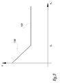
- figure 5 is a graph illustrating the evolution of a measured distance c in dependence of the height hv of the vehicle.
- For persons with reduced mobility are in particular meant persons in a wheelchair or persons who have difficulty boarding a vehicle such as a bus.
- Figure 1 is a schematic representation of the vertical cross-section of the structure of a
vehicle 2 equipped with a device 4 for accessing said vehicle for persons with reduced mobility. The plane of the cross-section is perpendicular to the direction of movement of thevehicle 2. - For example,
vehicle 2 is a public transport vehicle such as a bus. -
Vehicle 2 includes abody 6 equipped with adoor 8 to allow passengers to board or alightvehicle 2. Saidbody 6 rests on achassis 10. -
Vehicle 2 also includes afloor 12 designed to support passengers inside thevehicle 2. Thefloor 12 also rests on the chassis. - The
chassis 10 itself rests on the wheels of thevehicle 2 which rest on arolling surface 16 on the ground. - In order to simplify figure 1, only one
wheel 18 has been shown. -
Surface 16 is, for example, the surface of a road or any traffic route. -
Surface 16 is, here, assumed to be horizontal. - A
mechanism 20 to adjust the height hv of thefloor 12 with respect to thesurface 16 onvehicle 2 which rests, is provided for in this vehicle. - By way of example, the
mechanism 20 includes aninflatable suspension cushion 22 and acontrollable compressor 24 suitable to regulate the pressure inside thecushion 22. When the pressure inside thecushion 22 rises, the height hv rises and vice versa. - Here, the
cushion 22 is shown as being located between thechassis 10 and anaxle 28 of thewheel 18. - The device 4 is equipped with an
access ramp 30 that can be moved between an open position in which it reduces the space between thefloor 12 and adocking surface 32, and a retracted position (shown in figure 1) insidevehicle 2. - Here, the
surface 32 is the upper surface of anexterior platform 34 on which people with reduced mobility can move in order to board thevehicle 2 or, contrarily, to alight. Saidsurface 32 is situated at a height hT with respect tosurface 16. Height hT is measured in a direction perpendicular to thesurface 16. - Here, the
ramp 30 can be moved between its open position and its retracted position by acontrollable motor 38.Motor 38 is controlled by acontrol unit 40. Thecontrol unit 40 is able to receive a command to open out or on the contrary to retract, sent by the driver ofvehicle 2. - Device 4 also includes a
sensor 42 to measure a distance c and asensor 44 to measure a distance d fixed on thevehicle 2. -
Sensor 42 is able to measure distance c along a line ofsight 46. The line of sight is inclined at an angle α with respect to the vertical ofvehicle 2 in the cross-section drawing. - Here, P1 designates a plane integral with
vehicle 2 and parallel to thefloor 12. Plane P1 crosses the line ofsight 46 at the level of thesensor 42. - A plane P2 is also designated, integral with the
platform 34 and parallel to thedocking surface 32. Planes P1 and P2 are, here, parallel to each other and separated by a distance h measured in a direction that is perpendicular to plane P1. To make the illustration clearer, the distance h has been exaggerated in figure 1. - A plane P3 parallel to the
floor 12 is a median plane of theramp 30. -
Sensor 44 measures the distance d along a line ofsight 48. The line ofsight 48 is parallel to plane P1, aligned in a direction perpendicular to the direction in which thevehicle 2 is travelling, and directed towards theplatform 34. -
Sensors unit 40. - Finally,
unit 40 is able to guide themechanism 20 according to the distance h separating plane P1 from plane P2, so as to adjust the height of the device 4 according to the height hT of theplatform 34. - More precisely,
unit 40 is able to control thecompressor 24 to modify the pressure inside theinflatable cushion 22. -
Unit 40 also includes a memory containing the various thresholds and parameters necessary for it to work. - Figure 2 shows in unbroken lines a view from above of the
ramp 30 in its open position. In figure 2, abroken line 50 shows the limit of thevehicle body 6 vertically above thedoor 8, and abroken line 52 shows the limit of thesurface 32 on which passengers board and alight. - The dotted lines in figure 2 show the
ramp 30 in its retracted position.Ramp 30 can only be opened in the plane P3 around a vertical axis ofrotation 54. The direction in which theramp 30 opens is shown by an arrow on figure 2. - In its open position, the useful surface of the
ramp 30 onto which people with reduced mobility move when they want to board or alight from thevehicle 2, is approximately rectangular. The width of this active surface L is between 60cm and 1.5m, preferably in the range of 60cm and 1cm. The depth P of this active surface is between 10 and 50cm and preferably in the range of 25 and 35cm. - An
obstacle detector 58 is provided for on the surface of theramp 30 opposite theplatform 34 in its open position. - The functioning of device 4 shall now be described with the help of figure 3.
- When the
vehicle 2 stops alongside theplatform 34 and in response to a command from the driver instep 70, thesensor 44 measures the distance d. - Next, in
step 72,unit 40 checks that the distance d is less than a predetermined threshold S1. Should that not be the case,unit 40 prevents, instep 74, the opening of theramp 30. Indeed, the opening of the ramp in this case would not be at all helpful for persons with reduced mobility, as this opening would not cover more than 95% of the distance between theedges - On the contrary, that is to say if the measured distance d is less than the limit S1, distance h is measured, in
step 78. - More precisely, in an
operation 80, thesensor 42 measures distance c and transmits it tounit 40. Inoperation 82, whenunit 40 receives the distance c, said unit calculates distance h with the help of the following relation:
- Next, in
step 84,unit 40 checks that the measured distance h is comprised in a permissible operative range [S2 ; S3]. - If the measured distance h is not within the range [S2 ; S3], then in
step 86,unit 40 preventsramp 30 from opening. Indeed, the difference in height between planes P1 and P2 is such that it is impossible to adjust the height hv of the vehicle floor so as to bring plane P3 to the level of plane P2. - Should the measured height h be within the range [S2 ; S3], then in
step 88unit 40 guides themechanism 20 to adjust the height of thevehicle floor 12 according to the measured height h. More precisely, hereunit 40 guides themechanism 20 until plane P3 meets plane P2 or is distant from plane P2 by a distance of less than 5cm, and preferably less then 2cm. - Once the distance between plane P2 and plane P3 is less than 2cm, in
step 90 theunit 40 orders the opening of theramp 30. Instep 90,ramp 30 is opened from its retracted position to its open position. - In parallel to step 90, in
step 92,unit 40 constantly checks that thedetector 58 has not detected any obstacles. If it has,unit 40 immediately interrupts the opening of theramp 30, instep 94. If not, ramp 30 is opened to its fully open position. - Once
ramp 30 has been opened out, thedoor 8 is open and persons with reduced mobility can board or alight thevehicle 2. - In
step 96, while theramp 30 is in its open position,unit 40 regulates the height hv to maintain it constant. Thus, although the weight of thevehicle 2 changes due to the fact that passengers are boarding and alighting from the vehicle, the height hv remains constant and plane P3 remains at an acceptable distance from plane P2. -
Step 96 lasts untilunit 40 orders, withstep 98, the retraction of the access ramp.Step 98 is, for example, triggered by a command sent by the driver. - Figure 4 shows another process for accessing the
vehicle 2 with the help of the device 4. This process is identical to that in figure 3 with the exception ofstep 88, which is replaced bystep 110 to adjust the height hv. - At the beginning of step 100, when an
operation 112 takes place, thesensor 42 measures the distance c(hv). Next, withoperation 114,unit 40 guides themechanism 20 to vertically move the line ofsight 48 at a predetermined pitch Δh. For example,unit 40 gradually lowers the height hv from a maximum height hv. - Next, in
operation 116, thesensor 42 measures the new distance c (hv+Δh) . - In
operation 118,unit 40 once again lowers the line ofsight 48 at pitch Δh and, inoperation 120,sensor 42 measures the distance c(hv+2Δh). - Using the measured distances c(hv), c(hv+Δh) and c(hv+2Δh), in
operation 122unit 40 calculates the second derivative of distance c in relationship to height hv with the help, for example, of the following relation:
- In
operation 124,unit 40 checks whether the secondderivative 
- For example,
unit 40 compares the secondderivative 
second 
operation 126unit 40 guides themechanism 20 to take plane P3 to the level of plane P2, then step 110 stops and the process continues withsteps operation 126, distance d is used to determine the lowering of the vehicle floor that will allow plane P3 to be brought to the level of plane P2. - Indeed, when the line of
sight 46 points at the angle between thesurface 32 and the vertical of theplatform 34, the secondderivative 

- Figure 5 shows the evolution of the distance c according to the height of the
vehicle 2 in the specific case of theplatform 34. More precisely, when the line ofsight 46 points at thesurface 32, each time the height hv is lowered by the pitch Δh, distance c decreases. This is represented by a decliningstraight line 130 in figure 5. Distance c stops decreasing when the line of sight points at the vertical part ofplatform 34. This is represented by thestraight line 132 parallel to the axis of the abscissas. The point where thesestraight lines sight 46 points atedge 52. In this case, the second derivative of distance c with respect to height hv passes through a maximum when the height hv is gradually lowered from a maximum height. The process in figure 4 does not require knowledge of angle α and is more robust compared to an inclination of plane P2 with respect to plane P1. - Many other forms of implementation are possible. For example, once the height of the bus has been adjusted according to the height hT of the
platform 34, theramp 30 can be moved manually. In this variation, themotor 38 is not necessary. - As a variation, the plane P3 into which the
ramp 30 moves, is inclined with respect to planes P1 and P2. - Other methods are possible for measuring height h. For example, it is possible to equip the
vehicle 2 with a geolocalisation sensor such as a GPS sensor (Global Positioning System) connected to a database containing the geographic positions of each platform and their heights. In this embodiment, starting from the position measured by the GPS sensor on thevehicle 2, theunit 40 extracts from the database the height of the platform in front of whichvehicle 2 has stopped at that moment. - It is also possible to obtain the distance d from an automatic bus driving system, through reference markers placed on the road surface.
- The process in figure 4 can also be implemented by gradually increasing height hv from a low position.
- As a variation, the
sensor 42 is fitted to move in rotation around an axis that is parallel to the direction of movement of thevehicle 2, so as to allow the line ofsight 46 to move, varying the value of the angle α. In this variation,step 110 is replaced by a step in which it is not the height hv which is being varied at a pitch Δh, but instead angle α which is moved by pitch Δα inoperations sight 46 is pointing exactly at the end ofsurface 32 opposite thevehicle 2. - In order to move the
sensor 42 it is also possible to fix it onto theramp 30 such as, for example, at the end of the ramp. Next,ramp 30 is moved from its retracted position to its open position, resulting insensor 42 being moved. Height h is then measured by adapting one of the methods described above. Once the height h has been measured, the height of the floor is adjusted according to the height h measured. - Here, the
ramp 30 has been described in the specific case where it is formed of a single rigid plate in a single piece without any hinges. As a variation, the ramp could be formed of several plates, hinged together. - When
ramp 30 is moved from its retracted position to its open position, it moves by rotation only. As a variation, ramp 30 moves between its retracted and open positions by means of a translatory movement only. To this end, for example, the ramp is fitted onto a slide guide. More generally, the movement of the ramp between its retracted position and its open position could be a combination of rotation and translatory movement.
Claims (9)
- Transport vehicle for persons with reduced mobility, said vehicle having :- a floor (12) which supports passengers with reduced mobility,- a controllable mechanism (20) to adjust the height of the floor with respect to a rolling surface on which the vehicle rests, and- a device (4) to allow persons with reduced mobility to access the vehicle, equipped with a ramp (30) joined to the vehicle and movable between an open position, in which it reduces the space between the floor of the vehicle and a docking surface (32) on an exterior platform in order to aid the boarding or alighting of persons with reduced mobility, and a retracted position inside the vehicle, characterised in that said device includes a control unit (40) able to automatically guide the mechanism to adjust the height of the floor according to the height of the platform in a direction perpendicular to the rolling surface.
- Vehicle access device for persons with reduced mobility suitable to be used in a vehicle according to claim 1, said device being equipped with an access ramp (30) joined to the vehicle and movable between an open position in which it reduces the space between the floor of the vehicle and a docking surface (32) on an exterior platform in order to aid the boarding or alighting of persons with reduced mobility, and a retracted position inside the vehicle,
characterised in that said device includes a control unit (40) able to automatically guide the mechanism to adjust the height of the floor according to the height of the platform in a direction perpendicular to the rolling surface. - Device according to claim 2, characterised in that the control unit (40) is able to automatically guide the adjustment mechanism according to the distance h between a first and a second parallel planes (P1, P2), the first plane being integral with the floor and parallel to the floor and the second plane being integral with the platform and parallel to the docking surface, to regulate the height of the access device with respect to the docking surface.
- Device according to claim 2 or 3, characterised in that said access ramp (30) can only be moved along a plane parallel to the vehicle floor.
- Device according to any one of claims 2 to 4,
characterised in that the control unit (40) is able to automatically guide the adjustment mechanism to maintain the height of the floor in a predetermined operational range at least for as long as the ramp is in its open position. - Device according to any one of claims 2 to 5,
characterised in that the device includes at least one sensor (42) suitable for measuring a distance c along a line of sight (46) that can be moved with respect to the exterior platform when the vehicle stops, said distance c depending on the height of the platform, and in that said control unit (40) is able to guide the adjustment mechanism according to the position of an extreme of the second derivative of distance c with respect to a physical magnitude representing the position of the line of sight. - Process for accessing a vehicle for persons with reduced mobility, with the help of an access device according to any one of claims 2 to 6, characterised in that the process includes:- a step (90) in which the access ramp moves between its retracted position and its open position, and- a step (88) in which the adjustment mechanism for the floor height is automatically guided according to the height of the platform in a direction perpendicular to the rolling surface.
- Process according to claim 7, characterised in that the process includes a step (96) in which the adjustment mechanism is automatically guided to maintain the height of the floor within a predetermined range when the access ramp is in its open position.
- Process according to claim 7 or 8, characterised in that it includes:- a step (112, 116, 120) for measuring a distance c along a line of sight that can be moved with respect to the external platform when the vehicle stops, said distance c depending on the height of the platform, and- a step (144) in which the adjustment mechanism is guided according to the position of an extreme of the second derivative of distance c with respect to a physical magnitude that represents the position of the line of sight.
Applications Claiming Priority (1)
| Application Number | Priority Date | Filing Date | Title |
|---|---|---|---|
| FR0511760A FR2893499B1 (en) | 2005-11-21 | 2005-11-21 | VEHICLE, DEVICE AND METHOD FOR ACCESSING THE VEHICLE FOR PERSONS WITH REDUCED MOBILITY |
Publications (3)
| Publication Number | Publication Date |
|---|---|
| EP1787613A2 true EP1787613A2 (en) | 2007-05-23 |
| EP1787613A3 EP1787613A3 (en) | 2007-08-29 |
| EP1787613B1 EP1787613B1 (en) | 2010-08-18 |
Family
ID=36283864
Family Applications (1)
| Application Number | Title | Priority Date | Filing Date |
|---|---|---|---|
| EP06124449A Not-in-force EP1787613B1 (en) | 2005-11-21 | 2006-11-21 | Vehicle, device and process for accessing said vehicle by persons with reduced mobility |
Country Status (5)
| Country | Link |
|---|---|
| EP (1) | EP1787613B1 (en) |
| AT (1) | ATE477779T1 (en) |
| DE (1) | DE602006016217D1 (en) |
| ES (1) | ES2349562T3 (en) |
| FR (1) | FR2893499B1 (en) |
Cited By (7)
| Publication number | Priority date | Publication date | Assignee | Title |
|---|---|---|---|---|
| EP2674308A1 (en) * | 2012-06-16 | 2013-12-18 | WABCO GmbH | Apparatus and method for changing the height of a vehicle body |
| WO2020040685A1 (en) * | 2018-08-24 | 2020-02-27 | Scania Cv Ab | A method, performed by a control device, for controlling a vehicle height in relation to the road surface and a modularised vehicle comprising such a control device |
| WO2020117111A1 (en) * | 2018-12-07 | 2020-06-11 | Scania Cv Ab | A method, performed by a control device, for controlling a vehicle position in relation to a platform, a control device and a vehicle comprising such a control device |
| EP4071510A1 (en) * | 2021-04-07 | 2022-10-12 | KNORR-BREMSE Systeme für Nutzfahrzeuge GmbH | Sensor controlled system, vehicle and method |
| US11541913B2 (en) * | 2018-08-09 | 2023-01-03 | Alstom Transport Technologies | Vehicle height control method and associated vehicle |
| US12072418B2 (en) | 2020-11-04 | 2024-08-27 | Alstom Transport Technologies | Method for measuring a distance from a vehicle to a platform |
| US12409899B1 (en) * | 2024-06-11 | 2025-09-09 | Kawasaki Motors, Ltd. | Vehicle |
Families Citing this family (6)
| Publication number | Priority date | Publication date | Assignee | Title |
|---|---|---|---|---|
| DE102011000668C5 (en) * | 2011-02-11 | 2016-03-24 | Haldex Brake Products Gmbh | Method for driver assistance in a docking operation of a commercial vehicle on a ramp |
| ES2892322T3 (en) * | 2015-03-06 | 2022-02-03 | Spencer Italia Srl | Method and system for adjusting the height of the self-loading stretcher support in rescue vehicles and rescue vehicles equipped with said system |
| DE102016116861A1 (en) | 2016-09-08 | 2018-03-08 | Knorr-Bremse Systeme für Nutzfahrzeuge GmbH | System for the driverless operation of commercial vehicles |
| DE102016116856A1 (en) * | 2016-09-08 | 2018-03-08 | Knorr-Bremse Systeme für Nutzfahrzeuge GmbH | System and method for adjusting a height of at least a part of a commercial vehicle |
| US10336260B1 (en) | 2018-02-13 | 2019-07-02 | Ford Global Technologies, Llc | Deployable running board |
| DE102024104870A1 (en) * | 2024-02-21 | 2025-08-21 | Zf Cv Systems Global Gmbh | Vehicle and method for operating a vehicle |
Family Cites Families (6)
| Publication number | Priority date | Publication date | Assignee | Title |
|---|---|---|---|---|
| US3765692A (en) * | 1972-06-07 | 1973-10-16 | Ltv Aerospace Corp | Leveling system |
| DE3708294A1 (en) * | 1987-03-14 | 1988-09-29 | Graubremse Gmbh | Control system for raising and lowering the vehicle body of pneumatically sprung vehicles with level control |
| BE1007255A3 (en) * | 1993-06-30 | 1995-05-02 | Hool Nv | Telescopic ramp for a door of a low-floor bus |
| DE4330638C2 (en) * | 1993-09-10 | 1998-02-12 | Mbb Foerder & Hebesysteme | Device for trouble-free climbing and rolling over a ramp |
| US5573266A (en) * | 1995-02-13 | 1996-11-12 | Safe-T-Vans, Inc. | Vehicle body lowering system |
| AUPO029696A0 (en) * | 1996-06-06 | 1996-07-04 | Dodcor Pty Ltd | Ground level access vehicle |
-
2005
- 2005-11-21 FR FR0511760A patent/FR2893499B1/en not_active Expired - Fee Related
-
2006
- 2006-11-21 ES ES06124449T patent/ES2349562T3/en active Active
- 2006-11-21 DE DE602006016217T patent/DE602006016217D1/en active Active
- 2006-11-21 EP EP06124449A patent/EP1787613B1/en not_active Not-in-force
- 2006-11-21 AT AT06124449T patent/ATE477779T1/en not_active IP Right Cessation
Cited By (9)
| Publication number | Priority date | Publication date | Assignee | Title |
|---|---|---|---|---|
| EP2674308A1 (en) * | 2012-06-16 | 2013-12-18 | WABCO GmbH | Apparatus and method for changing the height of a vehicle body |
| US11541913B2 (en) * | 2018-08-09 | 2023-01-03 | Alstom Transport Technologies | Vehicle height control method and associated vehicle |
| WO2020040685A1 (en) * | 2018-08-24 | 2020-02-27 | Scania Cv Ab | A method, performed by a control device, for controlling a vehicle height in relation to the road surface and a modularised vehicle comprising such a control device |
| WO2020117111A1 (en) * | 2018-12-07 | 2020-06-11 | Scania Cv Ab | A method, performed by a control device, for controlling a vehicle position in relation to a platform, a control device and a vehicle comprising such a control device |
| US12072418B2 (en) | 2020-11-04 | 2024-08-27 | Alstom Transport Technologies | Method for measuring a distance from a vehicle to a platform |
| EP4071510A1 (en) * | 2021-04-07 | 2022-10-12 | KNORR-BREMSE Systeme für Nutzfahrzeuge GmbH | Sensor controlled system, vehicle and method |
| WO2022214253A1 (en) * | 2021-04-07 | 2022-10-13 | Knorr-Bremse Systeme für Nutzfahrzeuge GmbH | Sensor controlled system, vehicle and method |
| US12510363B2 (en) | 2021-04-07 | 2025-12-30 | Knorr-Bremse Systeme Fuer Nutzfahrzeuge Gmbh | Sensor controlled system, vehicle and method |
| US12409899B1 (en) * | 2024-06-11 | 2025-09-09 | Kawasaki Motors, Ltd. | Vehicle |
Also Published As
| Publication number | Publication date |
|---|---|
| FR2893499A1 (en) | 2007-05-25 |
| EP1787613A3 (en) | 2007-08-29 |
| EP1787613B1 (en) | 2010-08-18 |
| ES2349562T3 (en) | 2011-01-05 |
| FR2893499B1 (en) | 2008-09-26 |
| ATE477779T1 (en) | 2010-09-15 |
| DE602006016217D1 (en) | 2010-09-30 |
Similar Documents
| Publication | Publication Date | Title |
|---|---|---|
| EP1787613B1 (en) | Vehicle, device and process for accessing said vehicle by persons with reduced mobility | |
| US10835428B2 (en) | Integrated systems for passenger bus | |
| US11572084B2 (en) | Integrated systems for passenger bus | |
| US9050229B1 (en) | Fold out ramp | |
| KR101626260B1 (en) | Safety foothold for train platform | |
| US20190193505A1 (en) | System and method for adjusting a height of at least one part of a utility vehicle | |
| US4110859A (en) | Passenger loading ramp | |
| US12577785B2 (en) | Ascending mechanised access ramp (A-MAR) | |
| US6539877B1 (en) | Elevated transit vehicle | |
| CA2967549C (en) | A railway vehicle with a movable, vertical gap bridging entry threshold | |
| US6857507B2 (en) | Equipment for fine-positioning at least one deck of a multi-deck cage for a lift | |
| EP1859996B1 (en) | Transport vehicle equipped with access device for persons with reduced mobility | |
| CA2857427A1 (en) | Method-system of parking a vehicle (1) using only front road course and placement of the rear of the vehicle (1) in a final parking position by an auxiliary mechanism | |
| CN110625355B (en) | Auxiliary assembly device for suspension type railway vehicle bogie | |
| US12618254B2 (en) | Parking bays having a sloped floor, and parking apparatuses and parking systems including same | |
| US20240408988A1 (en) | Device and method for providing and stowing a charging cable at a charging station | |
| NL2011367C2 (en) | In-ground lifting system for lifting a vehicle and method there for. | |
| US6779960B1 (en) | Vehicle lift apparatus | |
| KR102339666B1 (en) | Docking ramp of boarding bridge | |
| CA3132143C (en) | Integrated systems for passenger bus | |
| KR20230003861A (en) | Bung car for supporting bung of annealing furnace | |
| NL2013389B1 (en) | System for blocking a vehicle, method there for and dock provided therewith. | |
| WO2024076555A1 (en) | Parking bays having a sloped floor, parking systems including same and related method for orienting a tray within such sloped parking bays | |
| KR20240064993A (en) | Automotive Vehicle Body Mounted Slope Parking Safety Retention Automatic Device | |
| KR20230103533A (en) | Control system and method for sliding ramp of bus |
Legal Events
| Date | Code | Title | Description |
|---|---|---|---|
| PUAI | Public reference made under article 153(3) epc to a published international application that has entered the european phase |
Free format text: ORIGINAL CODE: 0009012 |
|
| AK | Designated contracting states |
Kind code of ref document: A2 Designated state(s): AT BE BG CH CY CZ DE DK EE ES FI FR GB GR HU IE IS IT LI LT LU LV MC NL PL PT RO SE SI SK TR |
|
| AX | Request for extension of the european patent |
Extension state: AL BA HR MK YU |
|
| PUAL | Search report despatched |
Free format text: ORIGINAL CODE: 0009013 |
|
| AK | Designated contracting states |
Kind code of ref document: A3 Designated state(s): AT BE BG CH CY CZ DE DK EE ES FI FR GB GR HU IE IS IT LI LT LU LV MC NL PL PT RO SE SI SK TR |
|
| AX | Request for extension of the european patent |
Extension state: AL BA HR MK YU |
|
| 17P | Request for examination filed |
Effective date: 20080227 |
|
| AKX | Designation fees paid |
Designated state(s): AT BE BG CH CY CZ DE DK EE ES FI FR GB GR HU IE IS IT LI LT LU LV MC NL PL PT RO SE SI SK TR |
|
| GRAP | Despatch of communication of intention to grant a patent |
Free format text: ORIGINAL CODE: EPIDOSNIGR1 |
|
| GRAS | Grant fee paid |
Free format text: ORIGINAL CODE: EPIDOSNIGR3 |
|
| GRAA | (expected) grant |
Free format text: ORIGINAL CODE: 0009210 |
|
| AK | Designated contracting states |
Kind code of ref document: B1 Designated state(s): AT BE BG CH CY CZ DE DK EE ES FI FR GB GR HU IE IS IT LI LT LU LV MC NL PL PT RO SE SI SK TR |
|
| REG | Reference to a national code |
Ref country code: GB Ref legal event code: FG4D |
|
| REG | Reference to a national code |
Ref country code: CH Ref legal event code: EP |
|
| REG | Reference to a national code |
Ref country code: IE Ref legal event code: FG4D |
|
| REF | Corresponds to: |
Ref document number: 602006016217 Country of ref document: DE Date of ref document: 20100930 Kind code of ref document: P |
|
| REG | Reference to a national code |
Ref country code: NL Ref legal event code: T3 |
|
| REG | Reference to a national code |
Ref country code: SE Ref legal event code: TRGR |
|
| REG | Reference to a national code |
Ref country code: ES Ref legal event code: FG2A Effective date: 20101222 |
|
| LTIE | Lt: invalidation of european patent or patent extension |
Effective date: 20100818 |
|
| PG25 | Lapsed in a contracting state [announced via postgrant information from national office to epo] |
Ref country code: LT Free format text: LAPSE BECAUSE OF FAILURE TO SUBMIT A TRANSLATION OF THE DESCRIPTION OR TO PAY THE FEE WITHIN THE PRESCRIBED TIME-LIMIT Effective date: 20100818 Ref country code: FI Free format text: LAPSE BECAUSE OF FAILURE TO SUBMIT A TRANSLATION OF THE DESCRIPTION OR TO PAY THE FEE WITHIN THE PRESCRIBED TIME-LIMIT Effective date: 20100818 Ref country code: AT Free format text: LAPSE BECAUSE OF FAILURE TO SUBMIT A TRANSLATION OF THE DESCRIPTION OR TO PAY THE FEE WITHIN THE PRESCRIBED TIME-LIMIT Effective date: 20100818 |
|
| PG25 | Lapsed in a contracting state [announced via postgrant information from national office to epo] |
Ref country code: SI Free format text: LAPSE BECAUSE OF FAILURE TO SUBMIT A TRANSLATION OF THE DESCRIPTION OR TO PAY THE FEE WITHIN THE PRESCRIBED TIME-LIMIT Effective date: 20100818 Ref country code: PL Free format text: LAPSE BECAUSE OF FAILURE TO SUBMIT A TRANSLATION OF THE DESCRIPTION OR TO PAY THE FEE WITHIN THE PRESCRIBED TIME-LIMIT Effective date: 20100818 Ref country code: IS Free format text: LAPSE BECAUSE OF FAILURE TO SUBMIT A TRANSLATION OF THE DESCRIPTION OR TO PAY THE FEE WITHIN THE PRESCRIBED TIME-LIMIT Effective date: 20101218 Ref country code: PT Free format text: LAPSE BECAUSE OF FAILURE TO SUBMIT A TRANSLATION OF THE DESCRIPTION OR TO PAY THE FEE WITHIN THE PRESCRIBED TIME-LIMIT Effective date: 20101220 Ref country code: BG Free format text: LAPSE BECAUSE OF FAILURE TO SUBMIT A TRANSLATION OF THE DESCRIPTION OR TO PAY THE FEE WITHIN THE PRESCRIBED TIME-LIMIT Effective date: 20101118 Ref country code: CY Free format text: LAPSE BECAUSE OF FAILURE TO SUBMIT A TRANSLATION OF THE DESCRIPTION OR TO PAY THE FEE WITHIN THE PRESCRIBED TIME-LIMIT Effective date: 20100818 |
|
| PG25 | Lapsed in a contracting state [announced via postgrant information from national office to epo] |
Ref country code: BE Free format text: LAPSE BECAUSE OF FAILURE TO SUBMIT A TRANSLATION OF THE DESCRIPTION OR TO PAY THE FEE WITHIN THE PRESCRIBED TIME-LIMIT Effective date: 20100818 Ref country code: LV Free format text: LAPSE BECAUSE OF FAILURE TO SUBMIT A TRANSLATION OF THE DESCRIPTION OR TO PAY THE FEE WITHIN THE PRESCRIBED TIME-LIMIT Effective date: 20100818 Ref country code: GR Free format text: LAPSE BECAUSE OF FAILURE TO SUBMIT A TRANSLATION OF THE DESCRIPTION OR TO PAY THE FEE WITHIN THE PRESCRIBED TIME-LIMIT Effective date: 20101119 |
|
| PG25 | Lapsed in a contracting state [announced via postgrant information from national office to epo] |
Ref country code: DK Free format text: LAPSE BECAUSE OF FAILURE TO SUBMIT A TRANSLATION OF THE DESCRIPTION OR TO PAY THE FEE WITHIN THE PRESCRIBED TIME-LIMIT Effective date: 20100818 |
|
| PG25 | Lapsed in a contracting state [announced via postgrant information from national office to epo] |
Ref country code: RO Free format text: LAPSE BECAUSE OF FAILURE TO SUBMIT A TRANSLATION OF THE DESCRIPTION OR TO PAY THE FEE WITHIN THE PRESCRIBED TIME-LIMIT Effective date: 20100818 Ref country code: SK Free format text: LAPSE BECAUSE OF FAILURE TO SUBMIT A TRANSLATION OF THE DESCRIPTION OR TO PAY THE FEE WITHIN THE PRESCRIBED TIME-LIMIT Effective date: 20100818 Ref country code: EE Free format text: LAPSE BECAUSE OF FAILURE TO SUBMIT A TRANSLATION OF THE DESCRIPTION OR TO PAY THE FEE WITHIN THE PRESCRIBED TIME-LIMIT Effective date: 20100818 Ref country code: CZ Free format text: LAPSE BECAUSE OF FAILURE TO SUBMIT A TRANSLATION OF THE DESCRIPTION OR TO PAY THE FEE WITHIN THE PRESCRIBED TIME-LIMIT Effective date: 20100818 |
|
| PLBE | No opposition filed within time limit |
Free format text: ORIGINAL CODE: 0009261 |
|
| STAA | Information on the status of an ep patent application or granted ep patent |
Free format text: STATUS: NO OPPOSITION FILED WITHIN TIME LIMIT |
|
| PG25 | Lapsed in a contracting state [announced via postgrant information from national office to epo] |
Ref country code: MC Free format text: LAPSE BECAUSE OF NON-PAYMENT OF DUE FEES Effective date: 20101130 |
|
| REG | Reference to a national code |
Ref country code: CH Ref legal event code: PL |
|
| 26N | No opposition filed |
Effective date: 20110519 |
|
| PG25 | Lapsed in a contracting state [announced via postgrant information from national office to epo] |
Ref country code: LI Free format text: LAPSE BECAUSE OF NON-PAYMENT OF DUE FEES Effective date: 20101130 Ref country code: CH Free format text: LAPSE BECAUSE OF NON-PAYMENT OF DUE FEES Effective date: 20101130 |
|
| REG | Reference to a national code |
Ref country code: DE Ref legal event code: R097 Ref document number: 602006016217 Country of ref document: DE Effective date: 20110519 |
|
| PG25 | Lapsed in a contracting state [announced via postgrant information from national office to epo] |
Ref country code: IE Free format text: LAPSE BECAUSE OF NON-PAYMENT OF DUE FEES Effective date: 20101121 |
|
| PG25 | Lapsed in a contracting state [announced via postgrant information from national office to epo] |
Ref country code: LU Free format text: LAPSE BECAUSE OF NON-PAYMENT OF DUE FEES Effective date: 20101121 Ref country code: HU Free format text: LAPSE BECAUSE OF FAILURE TO SUBMIT A TRANSLATION OF THE DESCRIPTION OR TO PAY THE FEE WITHIN THE PRESCRIBED TIME-LIMIT Effective date: 20110219 |
|
| PG25 | Lapsed in a contracting state [announced via postgrant information from national office to epo] |
Ref country code: TR Free format text: LAPSE BECAUSE OF FAILURE TO SUBMIT A TRANSLATION OF THE DESCRIPTION OR TO PAY THE FEE WITHIN THE PRESCRIBED TIME-LIMIT Effective date: 20100818 |
|
| REG | Reference to a national code |
Ref country code: FR Ref legal event code: PLFP Year of fee payment: 10 |
|
| REG | Reference to a national code |
Ref country code: DE Ref legal event code: R082 Ref document number: 602006016217 Country of ref document: DE Representative=s name: SCHWABE SANDMAIR MARX PATENTANWAELTE RECHTSANW, DE Ref country code: DE Ref legal event code: R082 Ref document number: 602006016217 Country of ref document: DE Representative=s name: SSM SANDMAIR PATENTANWAELTE RECHTSANWALT PARTN, DE |
|
| REG | Reference to a national code |
Ref country code: FR Ref legal event code: PLFP Year of fee payment: 11 |
|
| REG | Reference to a national code |
Ref country code: FR Ref legal event code: PLFP Year of fee payment: 12 |
|
| PGFP | Annual fee paid to national office [announced via postgrant information from national office to epo] |
Ref country code: SE Payment date: 20221123 Year of fee payment: 17 Ref country code: NL Payment date: 20221124 Year of fee payment: 17 |
|
| REG | Reference to a national code |
Ref country code: NL Ref legal event code: PD Owner name: IVECO FRANCE S.A.S.; FR Free format text: DETAILS ASSIGNMENT: CHANGE OF OWNER(S), CHANGE OF LEGAL ENTITY; FORMER OWNER NAME: IVECO FRANCE S.A. Effective date: 20230406 |
|
| REG | Reference to a national code |
Ref country code: DE Ref legal event code: R081 Ref document number: 602006016217 Country of ref document: DE Owner name: IVECO FRANCE S.A.S., FR Free format text: FORMER OWNER: IVECO FRANCE S.A., VENISSIEUX, FR |
|
| P01 | Opt-out of the competence of the unified patent court (upc) registered |
Effective date: 20230522 |
|
| PGFP | Annual fee paid to national office [announced via postgrant information from national office to epo] |
Ref country code: GB Payment date: 20231121 Year of fee payment: 18 |
|
| PGFP | Annual fee paid to national office [announced via postgrant information from national office to epo] |
Ref country code: ES Payment date: 20231219 Year of fee payment: 18 |
|
| PGFP | Annual fee paid to national office [announced via postgrant information from national office to epo] |
Ref country code: IT Payment date: 20231113 Year of fee payment: 18 Ref country code: FR Payment date: 20231123 Year of fee payment: 18 Ref country code: DE Payment date: 20231127 Year of fee payment: 18 |
|
| REG | Reference to a national code |
Ref country code: ES Ref legal event code: PC2A Owner name: IVECO FRANCE S.A.S. Effective date: 20240614 |
|
| REG | Reference to a national code |
Ref country code: SE Ref legal event code: EUG |
|
| REG | Reference to a national code |
Ref country code: NL Ref legal event code: MM Effective date: 20231201 |
|
| PG25 | Lapsed in a contracting state [announced via postgrant information from national office to epo] |
Ref country code: SE Free format text: LAPSE BECAUSE OF NON-PAYMENT OF DUE FEES Effective date: 20231122 |
|
| PG25 | Lapsed in a contracting state [announced via postgrant information from national office to epo] |
Ref country code: NL Free format text: LAPSE BECAUSE OF NON-PAYMENT OF DUE FEES Effective date: 20231201 |
|
| PG25 | Lapsed in a contracting state [announced via postgrant information from national office to epo] |
Ref country code: NL Free format text: LAPSE BECAUSE OF NON-PAYMENT OF DUE FEES Effective date: 20231201 |
|
| REG | Reference to a national code |
Ref country code: DE Ref legal event code: R119 Ref document number: 602006016217 Country of ref document: DE |
|
| GBPC | Gb: european patent ceased through non-payment of renewal fee |
Effective date: 20241121 |
|
| PG25 | Lapsed in a contracting state [announced via postgrant information from national office to epo] |
Ref country code: DE Free format text: LAPSE BECAUSE OF NON-PAYMENT OF DUE FEES Effective date: 20250603 |
|
| PG25 | Lapsed in a contracting state [announced via postgrant information from national office to epo] |
Ref country code: IT Free format text: LAPSE BECAUSE OF NON-PAYMENT OF DUE FEES Effective date: 20241121 |
|
| PG25 | Lapsed in a contracting state [announced via postgrant information from national office to epo] |
Ref country code: GB Free format text: LAPSE BECAUSE OF NON-PAYMENT OF DUE FEES Effective date: 20241121 |
|
| PG25 | Lapsed in a contracting state [announced via postgrant information from national office to epo] |
Ref country code: FR Free format text: LAPSE BECAUSE OF NON-PAYMENT OF DUE FEES Effective date: 20241130 |
|
| REG | Reference to a national code |
Ref country code: ES Ref legal event code: FD2A Effective date: 20260102 |
|
| PG25 | Lapsed in a contracting state [announced via postgrant information from national office to epo] |
Ref country code: ES Free format text: LAPSE BECAUSE OF NON-PAYMENT OF DUE FEES Effective date: 20241122 |