EP1787495B1 - Combining audio signals using auditory scene analysis - Google Patents
Combining audio signals using auditory scene analysis Download PDFInfo
- Publication number
- EP1787495B1 EP1787495B1 EP05770949A EP05770949A EP1787495B1 EP 1787495 B1 EP1787495 B1 EP 1787495B1 EP 05770949 A EP05770949 A EP 05770949A EP 05770949 A EP05770949 A EP 05770949A EP 1787495 B1 EP1787495 B1 EP 1787495B1
- Authority
- EP
- European Patent Office
- Prior art keywords
- channel
- channels
- input
- audio
- time
- Prior art date
- Legal status (The legal status is an assumption and is not a legal conclusion. Google has not performed a legal analysis and makes no representation as to the accuracy of the status listed.)
- Expired - Lifetime
Links
Images

Classifications
-
- H—ELECTRICITY
- H04—ELECTRIC COMMUNICATION TECHNIQUE
- H04S—STEREOPHONIC SYSTEMS
- H04S3/00—Systems employing more than two channels, e.g. quadraphonic
- H04S3/02—Systems employing more than two channels, e.g. quadraphonic of the matrix type, i.e. in which input signals are combined algebraically, e.g. after having been phase shifted with respect to each other
-
- H—ELECTRICITY
- H04—ELECTRIC COMMUNICATION TECHNIQUE
- H04R—LOUDSPEAKERS, MICROPHONES, GRAMOPHONE PICK-UPS OR LIKE ACOUSTIC ELECTROMECHANICAL TRANSDUCERS; DEAF-AID SETS; PUBLIC ADDRESS SYSTEMS
- H04R3/00—Circuits for transducers, loudspeakers or microphones
- H04R3/02—Circuits for transducers, loudspeakers or microphones for preventing acoustic reaction, i.e. acoustic oscillatory feedback
-
- H—ELECTRICITY
- H04—ELECTRIC COMMUNICATION TECHNIQUE
- H04B—TRANSMISSION
- H04B1/00—Details of transmission systems, not covered by a single one of groups H04B3/00 - H04B13/00; Details of transmission systems not characterised by the medium used for transmission
- H04B1/06—Receivers
- H04B1/16—Circuits
- H04B1/20—Circuits for coupling gramophone pick-up, recorder output, or microphone to receiver
-
- H—ELECTRICITY
- H04—ELECTRIC COMMUNICATION TECHNIQUE
- H04S—STEREOPHONIC SYSTEMS
- H04S3/00—Systems employing more than two channels, e.g. quadraphonic
-
- H—ELECTRICITY
- H04—ELECTRIC COMMUNICATION TECHNIQUE
- H04S—STEREOPHONIC SYSTEMS
- H04S2420/00—Techniques used stereophonic systems covered by H04S but not provided for in its groups
- H04S2420/03—Application of parametric coding in stereophonic audio systems
Definitions
- the present invention is related to changing the number of channels in a multichannel audio signal in which some of the audio channels are combined.
- Applications include the presentation of multichannel audio in cinemas and vehicles.
- the invention includes not only methods but also corresponding computer program implementations and apparatus implementations.
- such audio material is presented through a playback system that has the same number of channels as the material.
- a 5.1 channel film soundtrack may be presented in a 5.1 channel cinema or through a 5.1 channel home theater audio system.
- a 5.1 channel film soundtrack may be presented in a 5.1 channel cinema or through a 5.1 channel home theater audio system.
- the playback of 5.1 channel material in a vehicle that has only two or four playback channels, or the playback of greater than 5.1 channel movie soundtracks in a cinema that is only equipped with a 5.1 channel system there is a need to combine or "downmix" some or all of the channels of the multichannel signal for presentation.
- the combining of channels may produce audible artifacts. For example, some frequency components may cancel while other frequency components reinforce or become louder. Most commonly, this is a result of the existence of similar or correlated audio signal components in two or more of the channels that are being combined.
- the combining of channels may be required for other purposes, not just for a reduction in the number of channels.
- upmixing the combining of channels to create an additional channel may lead to audible artifacts.
- Common techniques for minimizing mixing or channel-combining artifacts involve applying, for example, one or more of time, phase, and amplitude (or power) adjustments to the channels to be combined, to the resulting combined channel, or to both.
- Audio signals are inherently dynamic - that is, their characteristics change over time. Therefore, such adjustments to audio signals are typically calculated and applied in a dynamic manner. While removing some artifacts resulting from combining, such dynamic processing may introduce other artifacts.
- the present invention employs Auditory Scene Analysis so that, in general, dynamic processing adjustments are maintained substantially constant during auditory scenes or events and changes in such adjustments are permitted only at or near auditory scene or event boundaries.
- ASA auditory scene analysis
- WO 2004/019656 A2 discloses a process of by which, using an M:N variable matrix, M audio input signals, each associated with a direction, are translated to N audio output signals, each associated with a direction, wherein N is larger than M, M is two or more and N is a positive integer equal to three or more.
- variable matrix is controlled in response to measures of: (1) the relative levels of the input signals, and (2) the cross-correlation of the input signals so that a soundfield generated by the output signals has a compact sound image in the nominal ongoing primary direction of the input signals when the input signals are highly correlated, the image spreading from compact to broad as the correlation decreases and progressively splitting into multiple compact sound images, each in a direction associated with an input signal, as the correlation continues to decrease to highly uncorrelated.
- decoding modules each receiving two or more of the input signals and providing one or more output signals. The document does not disclose such decoding module that receives three input signals that represent, in order, consecutive spatial directions, and provides two output signals that represent the two non-consecutive ones of those three spatial directions.
- the document US 6,487,535 B1 discloses a subband audio coder that employs perfect/non-perfect reconstruction filters, predictive/non-predictive subband encoding, transient analysis, and psycho-acoustic/minimum mean-square-error (mmse) bit allocation over time, frequency and the multiple audio channels to encode/decode a data stream to generate high fidelity reconstructed audio.
- the audio coder windows the multi-channel audio signal such that the frame size, i.e. number of bytes, is constrained to lie in a desired range, and formats the encoded data so that the individual subframes can be played back as they are received thereby reducing latency.
- the main goal of the invention is to improve the sound quality of combined audio signals. This may be achieved, for example, by performing, variously, time, phase and/or amplitude (or power) correction to the audio signals, and by controlling such corrections at least in part with a measure of auditory scene analysis information.
- adjustments applied to the audio signals generally may be held relatively constant during an auditory event and allowed to change at or near boundaries or transitions between auditory events. Of course, such adjustments need not occur as frequently as every boundary.
- the control of such adjustments may be accomplished on a channel-by-channel basis in response to auditory event information in each channel. Alternatively, some or all of such adjustments may be accomplished in response to auditory event information that has been combined over all channels or fewer than all channels.
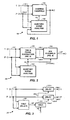
- FIG. 1 A generalized embodiment of the present invention is shown in FIG. 1 , wherein an audio channel combiner or combining process 100 is shown.
- a plurality of audio input channels, P input channels, 101-1 through 101-P are applied to a channel combiner or combining function ("Combine Channels") 102 and to an auditory scene analyzer or analysis function ("Auditory Scene Analysis") 103.
- Channels 1 through P may constitute some or all of a set of input channels.
- Combine Channels 102 combines the channels applied to it. Although such combination may be, for example, a linear, additive combining, the combination technique is not critical to the present invention.
- Combine Channels 102 In addition to combining the channels applied to it, Combine Channels 102 also dynamically applies one or more of time, phase, and amplitude or power adjustments to the channels to be combined, to the resulting combined channel, or to both the channels to be combined and the resulting combined channel. Such adjustments may be made for the purpose of improving the quality of the channel combining by reducing mixing or channel-combining artifacts.
- the particular adjustment techniques are not critical to the present invention. Examples of suitable techniques for combining and adjusting are set forth in United States Provisional Patent Application S.N.
- Auditory Scene Analysis 103 derives auditory scene information in accordance, for example, with techniques described in one or more of the above-identified applications by or some other suitable auditory scene analyzer or analysis process. Such information 104, which should include at least the location of boundaries between auditory events, is applied to Combine Channels 102. One or more of said adjustments are controlled at least in part by a measure of auditory events in one or more of the channels to be combined and/or the resulting combined channel.
- FIG. 2 shows an example of an audio signal processor or processing method 200 embodying aspects of the present invention.
- Signals 101-1 through 101-P from a plurality of audio channels 1 through P that are to be combined are applied to a time and/or phase correction device or process ("Time & Phase Correction") 202 and to an auditory scene analysis device or process ("Auditory Scene Analysis”) 103, as described in connection with FIG. 1 .
- Channels 1 through P may constitute some or all of a set of input channels.
- Auditory Scene Analysis 103 derives auditory scene information 104 and applies it to the Time & Phase Correction 202, which applies time and/or phase correction individually to each of the channels to be combined, as is described below in connection with FIG. 3 .
- the corrected channels 205-1 through 205-P are then applied to a channel mixing device or process ("Mix Channels") 206 that combines the channels to create a single output channel 207.
- Mix Channels 206 may also be controlled by the Auditory Scene Analysis information 104, as is described further below.
- An audio signal processor or processing method embodying aspects of the present invention as in the examples of FIGS. 1 and 2 may also combine various ones of channels 1 through P to produce more than one output channel.
- Auditory scene analysis research has shown that the ear uses several different auditory cues to identify the beginning and end of a perceived auditory event.
- one of the most powerful cues is a change in the spectral content of the audio signal.
- Auditory Scene Analysis 103 For each input channel, Auditory Scene Analysis 103 performs spectral analysis on the audio of each channel 1 through P at defined time intervals to create a sequence of frequency representations of the signal.
- successive representations may be compared in order to find a change in spectral content greater than a threshold. Finding such a change indicates an auditory event boundary between that pair of successive frequency representations, denoting approximately the end of one auditory event and the start of another.
- the locations of the auditory event boundaries for each input channel are output as components of the Auditory Scene Analysis information 104. Although this may be accomplished in the manner described in said above-identified applications, auditory events and their boundaries may be detected by other suitable techniques.
- Auditory events are perceived units of sound with characteristics that remain substantially constant throughout the event. If time, phase and/or amplitude (or power) adjustments, such as may be used in embodiments of the present invention, vary significantly within an auditory event, effects of such adjustments may become audible, constituting undesirable artifacts. By keeping adjustments constant throughout an event and only changing the adjustments sufficiently close to event boundaries, the similarity of an auditory event is not broken up and the changes are likely to be hidden among more noticeable changes in the audio content that inherently signify the event boundary.
- channel combining or "downmixing" parameters should be allowed to change only at auditory event boundaries, so that no dynamic changes occur within an event.
- practical systems for detecting auditory events typically operate in the digital domain in which blocks of digital audio samples in the time-domain are transformed into the frequency domain such that the time resolution of the auditory event boundaries have a fairly coarse time resolution, which resolution is related to the block length of the digital audio samples.
- event boundaries may be determined to within half a block length, or about 5.8 milliseconds for the example of a 512 sample block length in a system employing a 44.1 kHz sampling rate.
- each input channel is a discrete time-domain audio signal.
- This discrete signal may be partitioned into overlapping blocks of approximately 10.6 milliseconds, in which the overlap is approximately 5.3 milliseconds. For an audio sample rate of 48 kHz, this is equivalent to 512 sample blocks of which 256 samples overlaps with the previous block.
- Each block may be windowed using, for example, a Hanning window and transformed into the frequency domain using, for example, a Discrete Fourier Transform (implemented as a Fast Fourier Transform for speed). The power, in units of decibels (dB), is calculated for each spectral value and then the spectrum is normalized to the largest dB spectral value.
- Non-overlapping or partially overlapping blocks may be used to reduce the cost of computation.
- other window functions may be used, however the Hanning window has been found to be well suited to this application.
- the normalized frequency spectrum for a current block may be compared to the normalized spectrum from the next previous block to obtain a measure of their difference.
- a single difference measure may be calculated by summing the absolute value of the difference in the dB spectral values of the current and next previous spectrums. Such difference measure may then be compared to a threshold. If the difference measure is greater than the threshold, an event boundary is indicated between the current and previous block, otherwise no event boundary is indicated between the current and previous block.
- a suitable value for this threshold has been found to be 2500 (in units of dB). Thus, event boundaries may be determined within an accuracy of about half a block.
- the auditory event boundary information for each channel 1 through P is output as a component of the Auditory Scene Analysis information 104.
- Time and Phase Correction 202 looks for high correlation and time or phase differences between pairs of the input channels.
- FIG. 3 shows the Time and Phase Correction 202 in more detail.
- one channel of each pair is a reference channel.
- One suitable correlation detection technique is described below.
- Other suitable correlation detection techniques may be employed.
- the device or process attempts to reduce phase or time differences between the pair of channels by modifying the phase or time characteristics of the non-reference channel, thus reducing or eliminating audible channel-combining artifacts that would otherwise result from the combining of that pair of channels. Some of such artifacts may be described by way of an example.
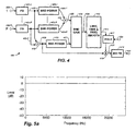
- FIG. 5a shows the magnitude spectrum of a white noise signal.
- FIG. 5a shows the magnitude spectrum of a white noise signal.
- 5b shows the magnitude spectrum resulting from the simple combining of a first channel consisting of white noise with a second signal that is the same white noise signal but delayed in time by approximately 0.21 milliseconds.
- a combination of the undelayed and delayed versions of the white noise signal has cancellations and spectral shaping, commonly called comb filtering, and audibly sounds very different to the white noise of each input signal.
- FIG. 3 shows a suitable device or method 300 for removing phase or time delays.
- Signals 101-1 through 101-P from each input audio channel are applied to a delay calculating device or process ("Calc Delays") 301 that outputs a delay-indicating signal 302 for each channel.
- the auditory event boundary information 104 which may have a component for each channel 1 through P, is used by a device or process that includes a temporary memory device or process ("Hold”) 303 to conditionally update delay signals 304-1 through 304-P that are used, respectively, by delay devices or functions (“Delay”) 305-1 through 305-P for each channel to produce output channels 306-1 through 306-P.
- Calc Delays 301 measures the relative delay between pairs of the input channels.
- a preferred method is, first, to select a reference channel from among the input channels. This reference may be fixed or it may vary over time. Allowing the reference channel to vary, overcomes the problem, for example, of a silent reference channel. If the reference channel varies, it may be determined, for example, by the channel loudness ( e.g ., loudest is the reference).
- the input audio signals for each input channel may be divided into overlapping blocks of approximately 10.6 milliseconds in length, overlapping by approximately 5.3 milliseconds. For an audio sample rate of 48 kHz, this is equivalent to 512 sample blocks of which 256 samples overlaps with the previous block.
- the cross-correlation may be performed using standard FFT based techniques to reduce execution time. Since both S 1 and S 2 are finite in length, the non-zero component of R 1,2 has a length of N 1 + N 2 -1.
- the lag l corresponding to the maximum element in R 1,2 represents the delay of S 2 relative to S 1 .
- l peak l for MAX R 1 , 2 l This lag or delay has the same sample units as the arrays S 1 and S 2 .
- the cross-correlation result for the current block is time smoothed with the cross-correlation result from the previous block using a first order infinite impulse response filter to create the smoothed cross-correlation Q 1,2.
- the following equation shows the filter computation where m denotes the current block and m-1 denotes the previous block.
- a useful value for ⁇ has been found to be 0.1.
- the lag l corresponding to the maximum element in Q 1,2 represents the delay of S 2 relative to S 1 .
- the lag or delay for each non-reference channel is output as a signal component of signal 302.
- a value of zero may also output as a component of signal 302, representing the delay of the reference channel.
- the range of delay that can be measured is proportional to the audio signal block size. That is, the larger the block size, the larger the range of delays that can be measured using this method.
- Hold 303 copies the delay value for that channel from 302 to the corresponding output channel delay signal 304.
- Hold 303 maintains the last delay value 304. In this way, time alignment changes occur at event boundaries and are therefore less likely to lead to audible artifacts.
- each of the Delays 305-1 through 305-P by default may be implemented to delay each channel by the absolute maximum delay that can be calculated by Calc Delays 301. Therefore, the total sample delay in each of the Delays 305-1 through 305-P is the sum of the respective input delay signal 304-1 through 304-P plus the default amount of delay. This allows for the signals 302 and 304 to be positive or negative, wherein negative indicates that a channel is advanced in time relative to the reference channel.
- any of the input delay signals 304-1 through 304-P change value, it may be necessary either to remove or replicate samples. Preferably, this is performed in a manner that does not cause audible artifacts. Such methods may include overlapping and crossfading samples.
- the output signals 306-1 to 306-P may be applied to a filterbank (see FIG. 4 ), it may be useful to combine the delay and filterbank such that the delay controls the alignment of the samples that are applied to the filterbank.
- a more complex method may measure and correct for time or phase differences in individual frequency bands or groups of frequency bands.
- both Calc Delays 301 and Delays 305-1 through 305-P may operate in the frequency domain, in which case Delays 305-1 through 305-P perform phase adjustments to bands or subbands, rather than delays in the time domain.
- signals 306-1 through 306-P are already in the frequency domain, negating the need for a subsequent Filterbank 401 ( FIG. 4 , as described below).
- Calc Delays 301 and Auditory Scene Analysis 103 may look ahead in the audio channels to provide more accurate estimates of event boundaries and time or phase corrections to be applied to within events.
- Mix Channels 206 of FIG. 2 are shown as device or process 400 in FIG. 4 , which shows how the input channels may be combined, with power correction, to create a downmixed output channel.
- this device or process may correct for residual frequency cancellations that were not completely corrected by Time & Phase Correction 203 in FIG. 2 . It also functions to maintain power conservation.
- Mix Channels 206 seeks to ensure that the power of the output downmix signal 414 ( FIG. 4 ) is substantially the same as the sum of the power of the time or phase adjusted input channels 205-1 through 205-P.
- the process may seek to ensure that the power in each frequency band of the downmixed signal is substantially the sum of the power of the corresponding frequency bands of the individual time or phase adjusted input channels.
- the process achieves this by comparing the band power from the downmixed channel to the band powers from the input channels and subsequently calculating a gain correction value for each band. Because changes in gain adjustments across both time and frequency may lead to audible artifacts, the gains preferably are both time and frequency smoothed before being applied to downmixed signal.
- This device or process represents one possible way of combining channels. Other suitable devices or processes may be employed. The particular combining device or process is not critical to the invention.
- the input audio signals for each input channel are time-domain signals and may have been divided into overlapping blocks of approximately 10.6 milliseconds in length, overlapping by approximately 5.3 milliseconds, as mentioned above. For an audio sample rate of 48 kHz, this is equivalent to 512 sample blocks of which 256 samples overlaps with the previous block.
- the sample blocks may be windowed and converted to the frequency domain by Filterbanks 401-1 through 401-P (one filterbank for each input signal). Although any one of various window types may be used, a Hanning window has been found to be suitable. Although any one of various time-domain to frequency-domain converters or conversion processes may be used, a suitable converter or conversion method may use a Discrete Fourier Transform (implemented as a Fast Fourier Transform for speed).
- the output of each filterbank is a respective array 402-1 through 402-P of complex spectral values - one value for each frequency band (or bin).
- BND Band
- a band power calculator or calculating process For each channel, a band power calculator or calculating process (“BND Power”) 403-1 through 403-P, respectively, computes and calculates the power of the complex spectral values 402-1 through 402-P, and outputs them as respective power spectra 404-1 through 404-P.
- Power spectrum values from each channel are summed in an additive combiner or combining function 415 to create a new combined power spectrum 405.
- Corresponding complex spectral values 402-1 through 402-P from each channel are also summed in an additive combiner or combining function 416 to create a downmix complex spectrum 406.
- the power of downmix complex spectrum 406 is computed in another power calculator or calculating process ("BND Power") 403 and output as the downmix power spectrum 407.
- a band gain calculator or calculating process divides the power spectrum 405 by the downmix power spectrum 407 to create an array of power gains or power ratios, one for each spectral value. If a downmix power spectral value is zero (causing the power gain to be infinite), then the corresponding power gain is set to "1.” The square root of the power gains is then calculated to create an array of amplitude gains 409.
- a limiter and smoother or limiting and smoothing function (Limit, Time & Frequency Smooth) 410 performs appropriate gain limiting and time/frequency smoothing.
- the spectral amplitude gains discussed just above may have a wide range. Best results may be obtained if the gains are kept within a limited range. For example, if any gain is greater an upper threshold, it is set equal to the upper threshold. Likewise, for example, if any gain is less than a lower threshold, it is set equal to the lower threshold.
- Useful thresholds are 0.5 and 2.0 (equivalent to ⁇ 6 dB).
- the spectral gains may then be temporally smoothed using a first-order infinite impulse response (IIR) filter.
- IIR infinite impulse response
- the temporally-smoothed gains are further smoothed across frequency to prevent large changes in gain between adjacent bands.
- the band gains are smoothed using a sliding five band (or approximately 470 Hz) average. That is, each bin is updated to be the average of itself and two adjacent bands both above and below in frequency.
- the edge values (bands 0 and N -1) are used repeatedly so that a five band average can still be performed.
- the smoothed band gains are output as signal 411 and multiplied by the downmix complex spectral values in a multiplier or multiplying function 419 to create the corrected downmix complex spectrum 412.
- the output signal 411 may be applied to the multiplier or multiplying function 419 via a temporary memory device or process ("Hold") 417 under control of the ASA information 104.
- Hold 417 operates in the same manner as Hold 303 of FIG. 3 .
- the gains could be held relatively constant during an event and only changed at event boundaries. In this way, possibly audible and dramatic gain changes during an event may be prevented.
- the downmix spectrum 412 from multiplier or multiplying function 419 is passed through an inverse filterbank or filterbank function ("INV FB") 413 to create blocks of output time samples.
- This filterbank is the inverse of the input filterbank 401. Adjacent blocks are overlapped with and added to previous blocks, as is well known, to create an output time-domain signal 414.
- One application of downmixing according to aspects of the present invention is the playback of 5.1 channel content in a motor vehicle.
- Motor vehicles may reproduce only four channels of 5.1 channel content, corresponding approximately to the Left, Right, Left Surround and Right Surround channels of such a system.
- Each channel is directed to one or more loudspeakers located in positions deemed suitable for reproduction of directional information associated with the particular channel.
- motor vehicles usually do not have a center loudspeaker position for reproduction of the Center channel in such a 5.1 playback system.
- it is known to attenuate the Center channel signal (by 3 dB or 6 dB for example) and to combine it with each of the Left and Right channel signals to provide a phantom center channel.
- such simple combining leads to artifacts previously described.
- channel combining or downmixing may be applied.
- the arrangement of FIG. 1 or the arrangement of FIG. 2 may be applied twice, once for combining the Left and Center signals, and once for combining Center and Right signals.
- the Center signal may be beneficial to denote the Center signal as the reference channel when combining it with each of the Left Channel and Right Channel signals such that the Time & Phase Correction 103 to which the Center channel signal is applied does not alter the time alignment or phase of the Center channel but only alters the time alignment or phase of the Left Channel and the Right Channel signals. Consequently, the Center Channel signal would not be adjusted differently in each of the two summations ( i.e ., the Left Channel plus Center Channel signals summation and the Right Channel plus Center Channel signals summation), thus ensuring that the phantom Center Channel image remains stable.
- the inverse may also be applicable. That is, time or phase adjust only the Center channel, again ensuring that the phantom Center Channel image remains stable.
- Another application of the downmixing according to aspects of the present invention is in the playback of multichannel audio in a cinema.
- Standards under development for the next generation of digital cinema systems require the delivery of up to, and soon to be more than, 16 channels of audio.
- the majority of installed cinema systems only provide 5.1 playback or "presentation” channels (as is well known, the "0.1” represents the low frequency "effects” channel). Therefore, until the playback systems are upgraded, at significant expense, there is the need to downmix content with more than 5.1 channels to 5.1 channels.
- Such downmixing or combining of channels leads to artifacts as discussed above.
- Time or phase adjustment serves to minimize the complete or partial cancellation of frequencies during downmixing.
- this channel preferably is denoted as the reference channel such that it is not time or phase adjusted differently when mixed to multiple output channels. This works well when the other channels do not have content that is substantially the same. However, situations can arise where two or more other channels have content that is the same or substantially the same. If such channels are combined into more than one output channel, when listening to the resulting output channels, the common content is perceived as a phantom image in space in a direction that is somewhere between the physical locations of the loudspeakers receiving those output channels.
- the Center channel signal is combined with each of the Left and Right channels for playback through the Left and Right loudspeakers, respectively.
- the Left and Right input channels often contain a plurality of signals (e.g ., instruments, vocals, dialog and/or effects), some of which are different and some of which are the same.
- the Center channel is denoted as the reference channel and is not time or phase adjusted.
- the Left channel is time or phase adjusted so as to produce minimal phase cancellation when combined with the Center channel
- the Right channel is time or phase adjusted so as to produce minimal phase cancellation when combined with the Center channel.
- the Left and Right channels are time or phase adjusted independently, signals that are common to the Left and Right channels may no longer have a phantom image between the physical locations of the Left and Right loudspeakers. Furthermore, the phantom image may not be localized to any one direction but may be spread throughout the listening space - an unnatural and undesirable effect.
- a solution to the adjustment problem is to extract signals that are common to more than one input channel from such input channels and place them in new and separate input channels. Although this increases the overall number of input channels P to be downmixed, it reduces spurious and undesirable phantom image distortion in the output downmixed channels.
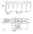
- An automotive example device or process 600 is shown in FIG. 6 for the case of three channels being downmixed to two. Signals common to the Left and Right input channels are extracted from the Left and Right channels into another new channel using any suitable channel multiplier or multiplication process ("Decorrelate Channels") 601 such as an active matrix decoder or other type of channel multiplier that extracts common signal components.
- Such a device may be characterized as a type of decorrelator or decorrelation function.
- the device or process 602 based on the arrangement of FIG. 2 , but here with two output channels, combines the four channels to create Left and Right playback channels L P and R P .
- the modified channels L D and R D are each mixed to only one playback channel; L P and R P respectively. Because they do not substantially contain any correlated content, the modified channels L D and R D , from which their common component C D has been extracted, can be time or phase adjusted without affecting any phantom center images present in the input channels L and R.
- one of the channels such as channel C D is denoted as the reference channel.
- the other channels L D , R D and C are then time and/or phase adjusted relative to the reference channel.
- L D and R D channels are unlikely to be correlated with the C channel, and since they are decorrelated from the C D channel by means of process 601, they may be passed to mix channels without any time or phase adjustment.
- Both original channel C and the derived center channel C D may be mixed with each of the intermediate channels L D and R D , respectively, in the Mix Channels portion of device or process 602 to produce the playback channels L P and R P .
- an equal proportion of C and C D has been found to produce satisfactory results, the exact proportion is not critical and may be other than equal. Consequently, any time and phase adjustment applied to C D and C will appear in both playback channels, thus maintaining the direction of phantom center images.
- Some attenuation may be required on each of the center channels since these channels are reproduced through two speakers, and not one. Also the amount of each of the center channels C and C D that is mixed into the output channels could be controlled by the listener. For example the listener may desire all of the original center channel C but some attenuation on the derived center channel C D .
- FIGS. 7a and 7b show the room or spatial locations of two sets of audio channels.
- FIG. 7a shows the approximate spatial locations of the channels as presented in the multichannel audio signal, otherwise denoted as "content channels”.
- FIG. 7b shows the approximate locations of channels, denoted as "playback channels,” that can be reproduced in a cinema that is equipped to play five channel audio material.
- Some of the content channels have corresponding playback channel locations; namely, the L, C. R, R S and L S channels.
- Other content channels do not have corresponding playback channel locations and therefore must be mixed into one or more of the playback channels.
- a typical approach is to combine such content channels into the nearest two playback channels.
- a solution includes extracting signals that are common to more than one input channel from such input channels and place them in new and separate channels.
- FIG. 7c shows a device or process 700 for the case in which five additional channels Q 1 to Q 5 are created by extracting information common to some combinations of the input or content channels using device or process ("Decorrelate Channels") 701.
- Device or process 701 may employ a suitable channel multiplication/decorrelation technique such as described above for use in the "Decorrelate Channels" device or function 601. The actual number and spatial location of these additional intermediate channels may vary according to variations in the audio signals contained in the content channels.
- the device or process 702 based on the arrangement of FIG.2 , but here with five output channels, combines the intermediate channels from Decorrelate Channels 701 to create the five playback channels.
- one of the intermediate channels such as the C channel
- all other intermediate channels be time and phase adjusted relative to this reference.
- channel Q 1 represents common signals extracted out of content channels L and C
- Q 1 and L C are being combined with intermediate channels L and C to create the playback channels L and C
- channel L C may be denoted as the reference channel.
- Intermediate channels L, C and Q 1 are then time or phase adjusted relative to the reference intermediate channel L C .
- Each smaller group of intermediate channels is time or phase adjusted in succession until all intermediate channels have been considered by the time and phase correction process.
- device or process 702 may assume a priori knowledge of the spatial locations of the content channels. Information regarding the number and spatial location of the additional intermediate channels may be assumed or may be passed to the device or process 702 from the decorrelating device or process 701 via path 703. This enables process or device 702 to combine the additional intermediate channels into, for example, the nearest two playback channels so that phantom image direction of these additional channels is maintained.
- the invention may be implemented in hardware or software, or a combination of both (e . g ., programmable logic arrays). Unless otherwise specified, the algorithms included as part of the invention are not inherently related to any particular computer or other apparatus. In particular, various general-purpose machines may be used with programs written in accordance with the teachings herein, or it may be more convenient to construct more specialized apparatus (e.g ., integrated circuits) to perform the required method steps. Thus, the invention may be implemented in one or more computer programs executing on one or more programmable computer systems each comprising at least one processor, at least one data storage system (including volatile and non-volatile memory and/or storage elements), at least one input device or port, and at least one output device or port. Program code is applied to input data to perform the functions described herein and generate output information. The output information is applied to one or more output devices, in known fashion.
- Program code is applied to input data to perform the functions described herein and generate output information.
- the output information is applied to one or more output devices, in
- Each such program may be implemented in any desired computer language (including machine, assembly, or high level procedural, logical, or object oriented programming languages) to communicate with a computer system.
- the language may be a compiled or interpreted language.
- Each such computer program is preferably stored on or downloaded to a storage media or device (e.g ., solid state memory or media, or magnetic or optical media) readable by a general or special purpose programmable computer, for configuring and operating the computer when the storage media or device is read by the computer system to perform the procedures described herein.
- a storage media or device e.g ., solid state memory or media, or magnetic or optical media
- the inventive system may also be considered to be implemented as a computer-readable storage medium, configured with a computer program, where the storage medium so configured causes a computer system to operate in a specific and predefined manner to perform the functions described herein.
Landscapes
- Engineering & Computer Science (AREA)
- Physics & Mathematics (AREA)
- Signal Processing (AREA)
- Acoustics & Sound (AREA)
- Otolaryngology (AREA)
- General Health & Medical Sciences (AREA)
- Health & Medical Sciences (AREA)
- Mathematical Optimization (AREA)
- Computer Networks & Wireless Communication (AREA)
- Pure & Applied Mathematics (AREA)
- Mathematical Physics (AREA)
- Mathematical Analysis (AREA)
- General Physics & Mathematics (AREA)
- Algebra (AREA)
- Theoretical Computer Science (AREA)
- Stereophonic System (AREA)
- Electrophonic Musical Instruments (AREA)
- Complex Calculations (AREA)
- Holo Graphy (AREA)
- Electrically Operated Instructional Devices (AREA)
- Measurement Of Current Or Voltage (AREA)
- Measurement And Recording Of Electrical Phenomena And Electrical Characteristics Of The Living Body (AREA)
- Measuring Pulse, Heart Rate, Blood Pressure Or Blood Flow (AREA)
Priority Applications (1)
| Application Number | Priority Date | Filing Date | Title |
|---|---|---|---|
| PL05770949T PL1787495T3 (pl) | 2004-08-03 | 2005-07-13 | Łączenie sygnałów akustycznych przy zastosowaniu analizy sceny akustycznej |
Applications Claiming Priority (2)
| Application Number | Priority Date | Filing Date | Title |
|---|---|---|---|
| US10/911,404 US7508947B2 (en) | 2004-08-03 | 2004-08-03 | Method for combining audio signals using auditory scene analysis |
| PCT/US2005/024630 WO2006019719A1 (en) | 2004-08-03 | 2005-07-13 | Combining audio signals using auditory scene analysis |
Publications (2)
| Publication Number | Publication Date |
|---|---|
| EP1787495A1 EP1787495A1 (en) | 2007-05-23 |
| EP1787495B1 true EP1787495B1 (en) | 2010-06-02 |
Family
ID=35115846
Family Applications (1)
| Application Number | Title | Priority Date | Filing Date |
|---|---|---|---|
| EP05770949A Expired - Lifetime EP1787495B1 (en) | 2004-08-03 | 2005-07-13 | Combining audio signals using auditory scene analysis |
Country Status (18)
| Country | Link |
|---|---|
| US (1) | US7508947B2 (enExample) |
| EP (1) | EP1787495B1 (enExample) |
| JP (1) | JP4740242B2 (enExample) |
| KR (1) | KR101161703B1 (enExample) |
| CN (1) | CN101002505B (enExample) |
| AT (1) | ATE470322T1 (enExample) |
| AU (1) | AU2005275257B2 (enExample) |
| BR (1) | BRPI0514059B1 (enExample) |
| CA (1) | CA2574834C (enExample) |
| DE (1) | DE602005021648D1 (enExample) |
| DK (1) | DK1787495T3 (enExample) |
| ES (1) | ES2346070T3 (enExample) |
| IL (1) | IL180712A (enExample) |
| MX (1) | MX2007001262A (enExample) |
| MY (1) | MY139731A (enExample) |
| PL (1) | PL1787495T3 (enExample) |
| TW (1) | TWI374435B (enExample) |
| WO (1) | WO2006019719A1 (enExample) |
Families Citing this family (53)
| Publication number | Priority date | Publication date | Assignee | Title |
|---|---|---|---|---|
| US7711123B2 (en) | 2001-04-13 | 2010-05-04 | Dolby Laboratories Licensing Corporation | Segmenting audio signals into auditory events |
| US7610205B2 (en) * | 2002-02-12 | 2009-10-27 | Dolby Laboratories Licensing Corporation | High quality time-scaling and pitch-scaling of audio signals |
| CA2992125C (en) | 2004-03-01 | 2018-09-25 | Dolby Laboratories Licensing Corporation | Reconstructing audio signals with multiple decorrelation techniques and differentially coded parameters |
| SE0400998D0 (sv) | 2004-04-16 | 2004-04-16 | Cooding Technologies Sweden Ab | Method for representing multi-channel audio signals |
| BRPI0513255B1 (pt) * | 2004-07-14 | 2019-06-25 | Koninklijke Philips Electronics N.V. | Dispositivo e método para converter um primeiro número de canais de áudio de entrada em um segundo número de canais de áudio de saída, sistema de áudio, e, meio de armazenamento legível por computador |
| US7508947B2 (en) | 2004-08-03 | 2009-03-24 | Dolby Laboratories Licensing Corporation | Method for combining audio signals using auditory scene analysis |
| US8090120B2 (en) | 2004-10-26 | 2012-01-03 | Dolby Laboratories Licensing Corporation | Calculating and adjusting the perceived loudness and/or the perceived spectral balance of an audio signal |
| CN101228575B (zh) * | 2005-06-03 | 2012-09-26 | 杜比实验室特许公司 | 利用侧向信息的声道重新配置 |
| EP1913577B1 (en) * | 2005-06-30 | 2021-05-05 | Lg Electronics Inc. | Apparatus for encoding an audio signal and method thereof |
| US8494667B2 (en) * | 2005-06-30 | 2013-07-23 | Lg Electronics Inc. | Apparatus for encoding and decoding audio signal and method thereof |
| TWI396188B (zh) | 2005-08-02 | 2013-05-11 | Dolby Lab Licensing Corp | 依聆聽事件之函數控制空間音訊編碼參數的技術 |
| WO2007043388A1 (ja) * | 2005-10-07 | 2007-04-19 | Matsushita Electric Industrial Co., Ltd. | 音響信号処理装置および音響信号処理方法 |
| TWI489886B (zh) * | 2006-04-03 | 2015-06-21 | Lg Electronics Inc | 音頻訊號解碼方法及其裝置 |
| TWI517562B (zh) | 2006-04-04 | 2016-01-11 | 杜比實驗室特許公司 | 用於將多聲道音訊信號之全面感知響度縮放一期望量的方法、裝置及電腦程式 |
| DE602006010323D1 (de) | 2006-04-13 | 2009-12-24 | Fraunhofer Ges Forschung | Audiosignaldekorrelator |
| KR101200615B1 (ko) | 2006-04-27 | 2012-11-12 | 돌비 레버러토리즈 라이쎈싱 코오포레이션 | 청각 이벤트 검출에 기반한 비-라우드니스를 이용한 자동 이득 제어 |
| CN101617360B (zh) * | 2006-09-29 | 2012-08-22 | 韩国电子通信研究院 | 用于编码和解码具有各种声道的多对象音频信号的设备和方法 |
| JP4940308B2 (ja) | 2006-10-20 | 2012-05-30 | ドルビー ラボラトリーズ ライセンシング コーポレイション | リセットを用いるオーディオダイナミクス処理 |
| JP2008262021A (ja) * | 2007-04-12 | 2008-10-30 | Hiromi Murakami | 電気楽器における位相切替装置 |
| DE102007018032B4 (de) * | 2007-04-17 | 2010-11-11 | Fraunhofer-Gesellschaft zur Förderung der angewandten Forschung e.V. | Erzeugung dekorrelierter Signale |
| ATE493731T1 (de) * | 2007-06-08 | 2011-01-15 | Dolby Lab Licensing Corp | Hybridableitung von surround-sound-audiokanälen durch steuerbares kombinieren von umgebungs- und matrixdekodierten signalkomponenten |
| CN101790758B (zh) * | 2007-07-13 | 2013-01-09 | 杜比实验室特许公司 | 用于控制音频信号的信号处理的设备和方法 |
| JP4471028B2 (ja) * | 2007-09-03 | 2010-06-02 | ソニー株式会社 | 情報処理装置、情報処理方法、およびプログラム |
| US8315398B2 (en) | 2007-12-21 | 2012-11-20 | Dts Llc | System for adjusting perceived loudness of audio signals |
| JP5195652B2 (ja) * | 2008-06-11 | 2013-05-08 | ソニー株式会社 | 信号処理装置、および信号処理方法、並びにプログラム |
| US8233629B2 (en) * | 2008-09-04 | 2012-07-31 | Dts, Inc. | Interaural time delay restoration system and method |
| DE102008056704B4 (de) * | 2008-11-11 | 2010-11-04 | Institut für Rundfunktechnik GmbH | Verfahren zum Erzeugen eines abwärtskompatiblen Tonformates |
| JP5163545B2 (ja) * | 2009-03-05 | 2013-03-13 | 富士通株式会社 | オーディオ復号装置及びオーディオ復号方法 |
| CN101533641B (zh) * | 2009-04-20 | 2011-07-20 | 华为技术有限公司 | 对多声道信号的声道延迟参数进行修正的方法和装置 |
| CN102307323B (zh) * | 2009-04-20 | 2013-12-18 | 华为技术有限公司 | 对多声道信号的声道延迟参数进行修正的方法 |
| JP5439586B2 (ja) | 2009-04-30 | 2014-03-12 | ドルビー ラボラトリーズ ライセンシング コーポレイション | 低複雑度の聴覚イベント境界検出 |
| CN102461208B (zh) * | 2009-06-19 | 2015-09-23 | 杜比实验室特许公司 | 用于可升级介质内核和引擎的用户特定特征 |
| US8538042B2 (en) | 2009-08-11 | 2013-09-17 | Dts Llc | System for increasing perceived loudness of speakers |
| EP2503618B1 (en) * | 2011-03-23 | 2014-01-01 | Semiconductor Energy Laboratory Co., Ltd. | Composite material, light-emitting element, light-emitting device, electronic device, and lighting device |
| US8804984B2 (en) | 2011-04-18 | 2014-08-12 | Microsoft Corporation | Spectral shaping for audio mixing |
| US9312829B2 (en) | 2012-04-12 | 2016-04-12 | Dts Llc | System for adjusting loudness of audio signals in real time |
| US9349384B2 (en) | 2012-09-19 | 2016-05-24 | Dolby Laboratories Licensing Corporation | Method and system for object-dependent adjustment of levels of audio objects |
| CN107690123B (zh) * | 2012-12-04 | 2021-04-02 | 三星电子株式会社 | 音频提供方法 |
| EP3515055A1 (en) | 2013-03-15 | 2019-07-24 | Dolby Laboratories Licensing Corp. | Normalization of soundfield orientations based on auditory scene analysis |
| EP2811758B1 (en) | 2013-06-06 | 2016-11-02 | Harman Becker Automotive Systems GmbH | Audio signal mixing |
| US10547960B2 (en) | 2014-09-01 | 2020-01-28 | Sony Semiconductor Solutions Corporation | Audio processing apparatus |
| RU2706581C2 (ru) | 2015-03-27 | 2019-11-19 | Фраунхофер-Гезелльшафт Цур Фердерунг Дер Ангевандтен Форшунг Е.Ф. | Устройство и способ обработки стереофонических сигналов для воспроизведения в автомобилях для достижения отдельного трехмерного звука посредством передних громкоговорителей |
| US10045145B2 (en) | 2015-12-18 | 2018-08-07 | Qualcomm Incorporated | Temporal offset estimation |
| US10210871B2 (en) * | 2016-03-18 | 2019-02-19 | Qualcomm Incorporated | Audio processing for temporally mismatched signals |
| EP3646323B1 (en) | 2017-06-27 | 2021-07-07 | Dolby International AB | Hybrid audio signal synchronization based on cross-correlation and attack analysis |
| CN107682529B (zh) * | 2017-09-07 | 2019-11-26 | 维沃移动通信有限公司 | 一种音频信号处理方法及移动终端 |
| WO2019076739A1 (en) * | 2017-10-16 | 2019-04-25 | Sony Europe Limited | AUDIO PROCESSING |
| US10462599B2 (en) * | 2018-03-21 | 2019-10-29 | Sonos, Inc. | Systems and methods of adjusting bass levels of multi-channel audio signals |
| CN108597527B (zh) * | 2018-04-19 | 2020-01-24 | 北京微播视界科技有限公司 | 多声道音频处理方法、装置、计算机可读存储介质和终端 |
| CN108495234B (zh) * | 2018-04-19 | 2020-01-07 | 北京微播视界科技有限公司 | 多声道音频处理方法、装置和计算机可读存储介质 |
| CN112437957B (zh) | 2018-07-27 | 2024-09-27 | 杜比实验室特许公司 | 用于全面收听的强加间隙插入 |
| DE102018127071B3 (de) * | 2018-10-30 | 2020-01-09 | Harman Becker Automotive Systems Gmbh | Audiosignalverarbeitung mit akustischer Echounterdrückung |
| WO2020206344A1 (en) | 2019-04-03 | 2020-10-08 | Dolby Laboratories Licensing Corporation | Scalable voice scene media server |
Family Cites Families (61)
| Publication number | Priority date | Publication date | Assignee | Title |
|---|---|---|---|---|
| US586228A (en) * | 1897-07-13 | Mounting prism-lights | ||
| JPS526601B2 (enExample) * | 1972-03-27 | 1977-02-23 | ||
| JPS4935003A (enExample) * | 1972-08-03 | 1974-04-01 | ||
| JPS5510654B2 (enExample) * | 1974-05-15 | 1980-03-18 | ||
| US4624009A (en) * | 1980-05-02 | 1986-11-18 | Figgie International, Inc. | Signal pattern encoder and classifier |
| US4464784A (en) * | 1981-04-30 | 1984-08-07 | Eventide Clockworks, Inc. | Pitch changer with glitch minimizer |
| US5040081A (en) * | 1986-09-23 | 1991-08-13 | Mccutchen David | Audiovisual synchronization signal generator using audio signature comparison |
| US5055939A (en) | 1987-12-15 | 1991-10-08 | Karamon John J | Method system & apparatus for synchronizing an auxiliary sound source containing multiple language channels with motion picture film video tape or other picture source containing a sound track |
| US5235646A (en) * | 1990-06-15 | 1993-08-10 | Wilde Martin D | Method and apparatus for creating de-correlated audio output signals and audio recordings made thereby |
| AU8053691A (en) | 1990-06-15 | 1992-01-07 | Auris Corp. | Method for eliminating the precedence effect in stereophonic sound systems and recording made with said method |
| GB2262992B (en) | 1990-06-21 | 1995-07-05 | Reynolds Software Inc | Method and apparatus for wave analysis and event recognition |
| DE69210689T2 (de) * | 1991-01-08 | 1996-11-21 | Dolby Lab Licensing Corp | Kodierer/dekodierer für mehrdimensionale schallfelder |
| US5175769A (en) | 1991-07-23 | 1992-12-29 | Rolm Systems | Method for time-scale modification of signals |
| DE69423922T2 (de) * | 1993-01-27 | 2000-10-05 | Koninkl Philips Electronics Nv | Tonsignalverarbeitungsanordnung zur Ableitung eines Mittelkanalsignals und audiovisuelles Wiedergabesystem mit solcher Verarbeitungsanordnung |
| US5956674A (en) * | 1995-12-01 | 1999-09-21 | Digital Theater Systems, Inc. | Multi-channel predictive subband audio coder using psychoacoustic adaptive bit allocation in frequency, time and over the multiple channels |
| US6430533B1 (en) * | 1996-05-03 | 2002-08-06 | Lsi Logic Corporation | Audio decoder core MPEG-1/MPEG-2/AC-3 functional algorithm partitioning and implementation |
| JPH1074097A (ja) | 1996-07-26 | 1998-03-17 | Ind Technol Res Inst | オーディオ信号のパラメータを変更する方法及び装置 |
| US6049766A (en) | 1996-11-07 | 2000-04-11 | Creative Technology Ltd. | Time-domain time/pitch scaling of speech or audio signals with transient handling |
| US5862228A (en) * | 1997-02-21 | 1999-01-19 | Dolby Laboratories Licensing Corporation | Audio matrix encoding |
| US6211919B1 (en) * | 1997-03-28 | 2001-04-03 | Tektronix, Inc. | Transparent embedment of data in a video signal |
| US6330672B1 (en) | 1997-12-03 | 2001-12-11 | At&T Corp. | Method and apparatus for watermarking digital bitstreams |
| GB2340351B (en) | 1998-07-29 | 2004-06-09 | British Broadcasting Corp | Data transmission |
| US6266644B1 (en) | 1998-09-26 | 2001-07-24 | Liquid Audio, Inc. | Audio encoding apparatus and methods |
| SE9903552D0 (sv) | 1999-01-27 | 1999-10-01 | Lars Liljeryd | Efficient spectral envelope coding using dynamic scalefactor grouping and time/frequency switching |
| US6760448B1 (en) * | 1999-02-05 | 2004-07-06 | Dolby Laboratories Licensing Corporation | Compatible matrix-encoded surround-sound channels in a discrete digital sound format |
| FR2802329B1 (fr) * | 1999-12-08 | 2003-03-28 | France Telecom | Procede de traitement d'au moins un flux binaire audio code organise sous la forme de trames |
| EP1310099B1 (en) | 2000-08-16 | 2005-11-02 | Dolby Laboratories Licensing Corporation | Modulating one or more parameters of an audio or video perceptual coding system in response to supplemental information |
| JP4624643B2 (ja) | 2000-08-31 | 2011-02-02 | ドルビー・ラボラトリーズ・ライセンシング・コーポレーション | オーディオ・マトリックス・デコーディング装置に関する方法 |
| CN1275498C (zh) | 2001-02-07 | 2006-09-13 | 多尔拜实验特许公司 | 声道转换方法 |
| WO2004019656A2 (en) | 2001-02-07 | 2004-03-04 | Dolby Laboratories Licensing Corporation | Audio channel spatial translation |
| US7461002B2 (en) * | 2001-04-13 | 2008-12-02 | Dolby Laboratories Licensing Corporation | Method for time aligning audio signals using characterizations based on auditory events |
| US7283954B2 (en) * | 2001-04-13 | 2007-10-16 | Dolby Laboratories Licensing Corporation | Comparing audio using characterizations based on auditory events |
| US7610205B2 (en) * | 2002-02-12 | 2009-10-27 | Dolby Laboratories Licensing Corporation | High quality time-scaling and pitch-scaling of audio signals |
| US7711123B2 (en) * | 2001-04-13 | 2010-05-04 | Dolby Laboratories Licensing Corporation | Segmenting audio signals into auditory events |
| MXPA03009357A (es) | 2001-04-13 | 2004-02-18 | Dolby Lab Licensing Corp | Escalamiento en el tiempo y escalamiento en el tono de alta calidad de senales de audio. |
| AU2002307533B2 (en) | 2001-05-10 | 2008-01-31 | Dolby Laboratories Licensing Corporation | Improving transient performance of low bit rate audio coding systems by reducing pre-noise |
| MXPA03010751A (es) | 2001-05-25 | 2005-03-07 | Dolby Lab Licensing Corp | Segmentacion de senales de audio en eventos auditivos. |
| AU2002240461B2 (en) | 2001-05-25 | 2007-05-17 | Dolby Laboratories Licensing Corporation | Comparing audio using characterizations based on auditory events |
| TW569551B (en) * | 2001-09-25 | 2004-01-01 | Roger Wallace Dressler | Method and apparatus for multichannel logic matrix decoding |
| JP4427937B2 (ja) * | 2001-10-05 | 2010-03-10 | オンキヨー株式会社 | 音響信号処理回路および音響再生装置 |
| US20040037421A1 (en) | 2001-12-17 | 2004-02-26 | Truman Michael Mead | Parital encryption of assembled bitstreams |
| ATE315823T1 (de) | 2002-02-18 | 2006-02-15 | Koninkl Philips Electronics Nv | Parametrische audiocodierung |
| ES2323294T3 (es) | 2002-04-22 | 2009-07-10 | Koninklijke Philips Electronics N.V. | Dispositivo de decodificacion con una unidad de decorrelacion. |
| AU2003264750A1 (en) * | 2002-05-03 | 2003-11-17 | Harman International Industries, Incorporated | Multi-channel downmixing device |
| EP1527655B1 (en) * | 2002-08-07 | 2006-10-04 | Dolby Laboratories Licensing Corporation | Audio channel spatial translation |
| DE10236694A1 (de) * | 2002-08-09 | 2004-02-26 | Fraunhofer-Gesellschaft zur Förderung der angewandten Forschung e.V. | Vorrichtung und Verfahren zum skalierbaren Codieren und Vorrichtung und Verfahren zum skalierbaren Decodieren |
| US7454331B2 (en) | 2002-08-30 | 2008-11-18 | Dolby Laboratories Licensing Corporation | Controlling loudness of speech in signals that contain speech and other types of audio material |
| US7676047B2 (en) * | 2002-12-03 | 2010-03-09 | Bose Corporation | Electroacoustical transducing with low frequency augmenting devices |
| ATE447755T1 (de) | 2003-02-06 | 2009-11-15 | Dolby Lab Licensing Corp | Kontinuierliche audiodatensicherung |
| AU2004248544B2 (en) | 2003-05-28 | 2010-02-18 | Dolby Laboratories Licensing Corporation | Method, apparatus and computer program for calculating and adjusting the perceived loudness of an audio signal |
| US7398207B2 (en) * | 2003-08-25 | 2008-07-08 | Time Warner Interactive Video Group, Inc. | Methods and systems for determining audio loudness levels in programming |
| US7394903B2 (en) * | 2004-01-20 | 2008-07-01 | Fraunhofer-Gesellschaft Zur Forderung Der Angewandten Forschung E.V. | Apparatus and method for constructing a multi-channel output signal or for generating a downmix signal |
| CA2992125C (en) | 2004-03-01 | 2018-09-25 | Dolby Laboratories Licensing Corporation | Reconstructing audio signals with multiple decorrelation techniques and differentially coded parameters |
| US7617109B2 (en) * | 2004-07-01 | 2009-11-10 | Dolby Laboratories Licensing Corporation | Method for correcting metadata affecting the playback loudness and dynamic range of audio information |
| FR2872910B1 (fr) | 2004-07-07 | 2006-10-13 | Nanoraptor Sa | Composant optique pour l'observation d'un echantillon nanometrique, systeme comprenant un tel composant, procede d'analyse mettant en oeuvre ce composant, et leurs applications |
| US7508947B2 (en) | 2004-08-03 | 2009-03-24 | Dolby Laboratories Licensing Corporation | Method for combining audio signals using auditory scene analysis |
| TW200638335A (en) | 2005-04-13 | 2006-11-01 | Dolby Lab Licensing Corp | Audio metadata verification |
| TWI397903B (zh) | 2005-04-13 | 2013-06-01 | Dolby Lab Licensing Corp | 編碼音訊之節約音量測量技術 |
| CN101228575B (zh) | 2005-06-03 | 2012-09-26 | 杜比实验室特许公司 | 利用侧向信息的声道重新配置 |
| TWI396188B (zh) | 2005-08-02 | 2013-05-11 | Dolby Lab Licensing Corp | 依聆聽事件之函數控制空間音訊編碼參數的技術 |
| KR101200615B1 (ko) | 2006-04-27 | 2012-11-12 | 돌비 레버러토리즈 라이쎈싱 코오포레이션 | 청각 이벤트 검출에 기반한 비-라우드니스를 이용한 자동 이득 제어 |
-
2004
- 2004-08-03 US US10/911,404 patent/US7508947B2/en not_active Expired - Lifetime
-
2005
- 2005-07-13 PL PL05770949T patent/PL1787495T3/pl unknown
- 2005-07-13 BR BRPI0514059-5A patent/BRPI0514059B1/pt active IP Right Grant
- 2005-07-13 EP EP05770949A patent/EP1787495B1/en not_active Expired - Lifetime
- 2005-07-13 WO PCT/US2005/024630 patent/WO2006019719A1/en not_active Ceased
- 2005-07-13 CA CA2574834A patent/CA2574834C/en not_active Expired - Lifetime
- 2005-07-13 MX MX2007001262A patent/MX2007001262A/es active IP Right Grant
- 2005-07-13 ES ES05770949T patent/ES2346070T3/es not_active Expired - Lifetime
- 2005-07-13 CN CN2005800261496A patent/CN101002505B/zh not_active Expired - Lifetime
- 2005-07-13 JP JP2007524817A patent/JP4740242B2/ja not_active Expired - Lifetime
- 2005-07-13 AU AU2005275257A patent/AU2005275257B2/en not_active Expired
- 2005-07-13 AT AT05770949T patent/ATE470322T1/de active
- 2005-07-13 DK DK05770949.5T patent/DK1787495T3/da active
- 2005-07-13 KR KR1020077002358A patent/KR101161703B1/ko not_active Expired - Lifetime
- 2005-07-13 DE DE602005021648T patent/DE602005021648D1/de not_active Expired - Lifetime
- 2005-07-15 TW TW094124108A patent/TWI374435B/zh not_active IP Right Cessation
- 2005-08-02 MY MYPI20053586A patent/MY139731A/en unknown
-
2007
- 2007-01-15 IL IL180712A patent/IL180712A/en active IP Right Grant
Also Published As
| Publication number | Publication date |
|---|---|
| AU2005275257B2 (en) | 2011-02-03 |
| US7508947B2 (en) | 2009-03-24 |
| MY139731A (en) | 2009-10-30 |
| CA2574834C (en) | 2013-07-09 |
| DK1787495T3 (da) | 2010-09-06 |
| US20060029239A1 (en) | 2006-02-09 |
| CA2574834A1 (en) | 2006-02-23 |
| ES2346070T3 (es) | 2010-10-08 |
| MX2007001262A (es) | 2007-04-18 |
| WO2006019719A1 (en) | 2006-02-23 |
| KR20070049146A (ko) | 2007-05-10 |
| TW200608352A (en) | 2006-03-01 |
| HK1101053A1 (en) | 2007-10-05 |
| IL180712A0 (en) | 2007-06-03 |
| IL180712A (en) | 2012-02-29 |
| ATE470322T1 (de) | 2010-06-15 |
| BRPI0514059B1 (pt) | 2019-11-12 |
| PL1787495T3 (pl) | 2010-10-29 |
| JP2008509600A (ja) | 2008-03-27 |
| KR101161703B1 (ko) | 2012-07-03 |
| DE602005021648D1 (de) | 2010-07-15 |
| BRPI0514059A (pt) | 2008-05-27 |
| AU2005275257A1 (en) | 2006-02-23 |
| JP4740242B2 (ja) | 2011-08-03 |
| EP1787495A1 (en) | 2007-05-23 |
| CN101002505A (zh) | 2007-07-18 |
| CN101002505B (zh) | 2011-08-10 |
| TWI374435B (en) | 2012-10-11 |
Similar Documents
| Publication | Publication Date | Title |
|---|---|---|
| EP1787495B1 (en) | Combining audio signals using auditory scene analysis | |
| JP5149968B2 (ja) | スピーチ信号処理を含むマルチチャンネル信号を生成するための装置および方法 | |
| JP4804532B2 (ja) | 無相関信号の包絡線整形 | |
| KR100635022B1 (ko) | 다채널 다운믹싱 장치 | |
| KR101256555B1 (ko) | 청각 이벤트의 함수에 따라서 공간 오디오 코딩파라미터들을 제어 | |
| EP1738356B1 (en) | Apparatus and method for generating multi-channel synthesizer control signal and apparatus and method for multi-channel synthesizing | |
| EP2614659B1 (en) | Upmixing method and system for multichannel audio reproduction | |
| US11115768B2 (en) | Binaural dialogue enhancement | |
| EP2896221A1 (en) | Apparatus and method for providing enhanced guided downmix capabilities for 3d audio | |
| EP2730102B1 (en) | Method and apparatus for decomposing a stereo recording using frequency-domain processing employing a spectral weights generator | |
| WO2014166863A1 (en) | Apparatus and method for center signal scaling and stereophonic enhancement based on a signal-to-downmix ratio | |
| HK1101053B (en) | Combining audio signals using auditory scene analysis | |
| Faller | Pseudostereophony revisited | |
| HK1197782B (en) | Method and apparatus for decomposing a stereo recording using frequency-domain processing employing a spectral subtractor | |
| HK1197782A (en) | Method and apparatus for decomposing a stereo recording using frequency-domain processing employing a spectral subtractor | |
| HK1197959B (en) | Method and apparatus for decomposing a stereo recording using frequency-domain processing employing a spectral weights generator |
Legal Events
| Date | Code | Title | Description |
|---|---|---|---|
| PUAI | Public reference made under article 153(3) epc to a published international application that has entered the european phase |
Free format text: ORIGINAL CODE: 0009012 |
|
| 17P | Request for examination filed |
Effective date: 20070228 |
|
| AK | Designated contracting states |
Kind code of ref document: A1 Designated state(s): AT BE BG CH CY CZ DE DK EE ES FI FR GB GR HU IE IS IT LI LT LU LV MC NL PL PT RO SE SI SK TR |
|
| REG | Reference to a national code |
Ref country code: HK Ref legal event code: DE Ref document number: 1101053 Country of ref document: HK |
|
| DAX | Request for extension of the european patent (deleted) | ||
| 17Q | First examination report despatched |
Effective date: 20090219 |
|
| GRAP | Despatch of communication of intention to grant a patent |
Free format text: ORIGINAL CODE: EPIDOSNIGR1 |
|
| GRAS | Grant fee paid |
Free format text: ORIGINAL CODE: EPIDOSNIGR3 |
|
| GRAA | (expected) grant |
Free format text: ORIGINAL CODE: 0009210 |
|
| AK | Designated contracting states |
Kind code of ref document: B1 Designated state(s): AT BE BG CH CY CZ DE DK EE ES FI FR GB GR HU IE IS IT LI LT LU LV MC NL PL PT RO SE SI SK TR |
|
| REG | Reference to a national code |
Ref country code: GB Ref legal event code: FG4D |
|
| REG | Reference to a national code |
Ref country code: CH Ref legal event code: EP |
|
| REG | Reference to a national code |
Ref country code: RO Ref legal event code: EPE |
|
| REG | Reference to a national code |
Ref country code: NL Ref legal event code: T3 |
|
| REG | Reference to a national code |
Ref country code: IE Ref legal event code: FG4D |
|
| REF | Corresponds to: |
Ref document number: 602005021648 Country of ref document: DE Date of ref document: 20100715 Kind code of ref document: P |
|
| REG | Reference to a national code |
Ref country code: CH Ref legal event code: NV Representative=s name: E. BLUM & CO. AG PATENT- UND MARKENANWAELTE VSP |
|
| REG | Reference to a national code |
Ref country code: SE Ref legal event code: TRGR |
|
| REG | Reference to a national code |
Ref country code: DK Ref legal event code: T3 |
|
| REG | Reference to a national code |
Ref country code: HK Ref legal event code: GR Ref document number: 1101053 Country of ref document: HK |
|
| REG | Reference to a national code |
Ref country code: ES Ref legal event code: FG2A Ref document number: 2346070 Country of ref document: ES Kind code of ref document: T3 |
|
| PG25 | Lapsed in a contracting state [announced via postgrant information from national office to epo] |
Ref country code: LT Free format text: LAPSE BECAUSE OF FAILURE TO SUBMIT A TRANSLATION OF THE DESCRIPTION OR TO PAY THE FEE WITHIN THE PRESCRIBED TIME-LIMIT Effective date: 20100602 |
|
| REG | Reference to a national code |
Ref country code: PL Ref legal event code: T3 |
|
| LTIE | Lt: invalidation of european patent or patent extension |
Effective date: 20100602 |
|
| PG25 | Lapsed in a contracting state [announced via postgrant information from national office to epo] |
Ref country code: SI Free format text: LAPSE BECAUSE OF FAILURE TO SUBMIT A TRANSLATION OF THE DESCRIPTION OR TO PAY THE FEE WITHIN THE PRESCRIBED TIME-LIMIT Effective date: 20100602 Ref country code: LV Free format text: LAPSE BECAUSE OF FAILURE TO SUBMIT A TRANSLATION OF THE DESCRIPTION OR TO PAY THE FEE WITHIN THE PRESCRIBED TIME-LIMIT Effective date: 20100602 |
|
| PG25 | Lapsed in a contracting state [announced via postgrant information from national office to epo] |
Ref country code: GR Free format text: LAPSE BECAUSE OF FAILURE TO SUBMIT A TRANSLATION OF THE DESCRIPTION OR TO PAY THE FEE WITHIN THE PRESCRIBED TIME-LIMIT Effective date: 20100903 Ref country code: CY Free format text: LAPSE BECAUSE OF FAILURE TO SUBMIT A TRANSLATION OF THE DESCRIPTION OR TO PAY THE FEE WITHIN THE PRESCRIBED TIME-LIMIT Effective date: 20100602 |
|
| PG25 | Lapsed in a contracting state [announced via postgrant information from national office to epo] |
Ref country code: EE Free format text: LAPSE BECAUSE OF FAILURE TO SUBMIT A TRANSLATION OF THE DESCRIPTION OR TO PAY THE FEE WITHIN THE PRESCRIBED TIME-LIMIT Effective date: 20100602 |
|
| PG25 | Lapsed in a contracting state [announced via postgrant information from national office to epo] |
Ref country code: PT Free format text: LAPSE BECAUSE OF FAILURE TO SUBMIT A TRANSLATION OF THE DESCRIPTION OR TO PAY THE FEE WITHIN THE PRESCRIBED TIME-LIMIT Effective date: 20101004 Ref country code: IS Free format text: LAPSE BECAUSE OF FAILURE TO SUBMIT A TRANSLATION OF THE DESCRIPTION OR TO PAY THE FEE WITHIN THE PRESCRIBED TIME-LIMIT Effective date: 20101002 Ref country code: MC Free format text: LAPSE BECAUSE OF NON-PAYMENT OF DUE FEES Effective date: 20100731 Ref country code: SK Free format text: LAPSE BECAUSE OF FAILURE TO SUBMIT A TRANSLATION OF THE DESCRIPTION OR TO PAY THE FEE WITHIN THE PRESCRIBED TIME-LIMIT Effective date: 20100602 |
|
| REG | Reference to a national code |
Ref country code: HU Ref legal event code: AG4A Ref document number: E009461 Country of ref document: HU |
|
| PLBE | No opposition filed within time limit |
Free format text: ORIGINAL CODE: 0009261 |
|
| STAA | Information on the status of an ep patent application or granted ep patent |
Free format text: STATUS: NO OPPOSITION FILED WITHIN TIME LIMIT |
|
| 26N | No opposition filed |
Effective date: 20110303 |
|
| REG | Reference to a national code |
Ref country code: DE Ref legal event code: R097 Ref document number: 602005021648 Country of ref document: DE Effective date: 20110302 |
|
| PG25 | Lapsed in a contracting state [announced via postgrant information from national office to epo] |
Ref country code: IE Free format text: LAPSE BECAUSE OF NON-PAYMENT OF DUE FEES Effective date: 20100713 |
|
| PG25 | Lapsed in a contracting state [announced via postgrant information from national office to epo] |
Ref country code: LU Free format text: LAPSE BECAUSE OF NON-PAYMENT OF DUE FEES Effective date: 20100713 |
|
| REG | Reference to a national code |
Ref country code: FR Ref legal event code: PLFP Year of fee payment: 12 |
|
| REG | Reference to a national code |
Ref country code: FR Ref legal event code: PLFP Year of fee payment: 13 |
|
| REG | Reference to a national code |
Ref country code: FR Ref legal event code: PLFP Year of fee payment: 14 |
|
| P01 | Opt-out of the competence of the unified patent court (upc) registered |
Effective date: 20230512 |
|
| PGFP | Annual fee paid to national office [announced via postgrant information from national office to epo] |
Ref country code: GB Payment date: 20240620 Year of fee payment: 20 |
|
| PGFP | Annual fee paid to national office [announced via postgrant information from national office to epo] |
Ref country code: DK Payment date: 20240619 Year of fee payment: 20 |
|
| PGFP | Annual fee paid to national office [announced via postgrant information from national office to epo] |
Ref country code: NL Payment date: 20240619 Year of fee payment: 20 |
|
| PGFP | Annual fee paid to national office [announced via postgrant information from national office to epo] |
Ref country code: CZ Payment date: 20240625 Year of fee payment: 20 |
|
| PGFP | Annual fee paid to national office [announced via postgrant information from national office to epo] |
Ref country code: FR Payment date: 20240619 Year of fee payment: 20 Ref country code: FI Payment date: 20240619 Year of fee payment: 20 |
|
| PGFP | Annual fee paid to national office [announced via postgrant information from national office to epo] |
Ref country code: PL Payment date: 20240621 Year of fee payment: 20 |
|
| PGFP | Annual fee paid to national office [announced via postgrant information from national office to epo] |
Ref country code: SE Payment date: 20240619 Year of fee payment: 20 Ref country code: BE Payment date: 20240619 Year of fee payment: 20 |
|
| PGFP | Annual fee paid to national office [announced via postgrant information from national office to epo] |
Ref country code: IT Payment date: 20240619 Year of fee payment: 20 |
|
| PGFP | Annual fee paid to national office [announced via postgrant information from national office to epo] |
Ref country code: BG Payment date: 20240702 Year of fee payment: 20 |
|
| PGFP | Annual fee paid to national office [announced via postgrant information from national office to epo] |
Ref country code: DE Payment date: 20240619 Year of fee payment: 20 |
|
| PGFP | Annual fee paid to national office [announced via postgrant information from national office to epo] |
Ref country code: CH Payment date: 20240801 Year of fee payment: 20 Ref country code: ES Payment date: 20240802 Year of fee payment: 20 |
|
| PGFP | Annual fee paid to national office [announced via postgrant information from national office to epo] |
Ref country code: AT Payment date: 20240620 Year of fee payment: 20 |
|
| PGFP | Annual fee paid to national office [announced via postgrant information from national office to epo] |
Ref country code: HU Payment date: 20240709 Year of fee payment: 20 |
|
| PGFP | Annual fee paid to national office [announced via postgrant information from national office to epo] |
Ref country code: RO Payment date: 20240715 Year of fee payment: 20 |
|
| PGFP | Annual fee paid to national office [announced via postgrant information from national office to epo] |
Ref country code: TR Payment date: 20240702 Year of fee payment: 20 |
|
| REG | Reference to a national code |
Ref country code: DE Ref legal event code: R071 Ref document number: 602005021648 Country of ref document: DE |
|
| REG | Reference to a national code |
Ref country code: DK Ref legal event code: EUP Expiry date: 20250713 |
|
| REG | Reference to a national code |
Ref country code: CH Ref legal event code: PL |
|
| REG | Reference to a national code |
Ref country code: NL Ref legal event code: MK Effective date: 20250712 |
|
| PG25 | Lapsed in a contracting state [announced via postgrant information from national office to epo] |
Ref country code: CZ Free format text: LAPSE BECAUSE OF EXPIRATION OF PROTECTION Effective date: 20250713 |
|
| REG | Reference to a national code |
Ref country code: ES Ref legal event code: FD2A Effective date: 20250728 |
|
| REG | Reference to a national code |
Ref country code: GB Ref legal event code: PE20 Expiry date: 20250712 |
|
| REG | Reference to a national code |
Ref country code: BE Ref legal event code: MK Effective date: 20250713 |
|
| REG | Reference to a national code |
Ref country code: SE Ref legal event code: EUG |
|
| REG | Reference to a national code |
Ref country code: AT Ref legal event code: MK07 Ref document number: 470322 Country of ref document: AT Kind code of ref document: T Effective date: 20250713 |
|
| PG25 | Lapsed in a contracting state [announced via postgrant information from national office to epo] |
Ref country code: ES Free format text: LAPSE BECAUSE OF EXPIRATION OF PROTECTION Effective date: 20250714 |