EP1786964B1 - Netting material with reflective or luminescent marker - Google Patents
Netting material with reflective or luminescent marker Download PDFInfo
- Publication number
- EP1786964B1 EP1786964B1 EP04769307A EP04769307A EP1786964B1 EP 1786964 B1 EP1786964 B1 EP 1786964B1 EP 04769307 A EP04769307 A EP 04769307A EP 04769307 A EP04769307 A EP 04769307A EP 1786964 B1 EP1786964 B1 EP 1786964B1
- Authority
- EP
- European Patent Office
- Prior art keywords
- netting
- reflective
- indicator strip
- ribbons
- strip
- Prior art date
- Legal status (The legal status is an assumption and is not a legal conclusion. Google has not performed a legal analysis and makes no representation as to the accuracy of the status listed.)
- Expired - Lifetime
Links
- 239000000463 material Substances 0.000 title claims abstract description 64
- 239000003550 marker Substances 0.000 title description 12
- 238000000034 method Methods 0.000 claims description 10
- 239000002245 particle Substances 0.000 claims description 3
- 239000011324 bead Substances 0.000 claims description 2
- 239000011521 glass Substances 0.000 claims description 2
- 238000009940 knitting Methods 0.000 claims description 2
- 230000000007 visual effect Effects 0.000 claims description 2
- 239000003086 colorant Substances 0.000 claims 1
- 239000000758 substrate Substances 0.000 claims 1
- 238000013459 approach Methods 0.000 description 4
- 229920000098 polyolefin Polymers 0.000 description 4
- 238000004519 manufacturing process Methods 0.000 description 3
- -1 polypropylene Polymers 0.000 description 3
- 239000007787 solid Substances 0.000 description 2
- 239000004677 Nylon Substances 0.000 description 1
- 239000004698 Polyethylene Substances 0.000 description 1
- 239000004743 Polypropylene Substances 0.000 description 1
- 230000003466 anti-cipated effect Effects 0.000 description 1
- 230000002708 enhancing effect Effects 0.000 description 1
- 229920000092 linear low density polyethylene Polymers 0.000 description 1
- 239000004707 linear low-density polyethylene Substances 0.000 description 1
- 238000005259 measurement Methods 0.000 description 1
- 239000002184 metal Substances 0.000 description 1
- 229920001778 nylon Polymers 0.000 description 1
- 238000004806 packaging method and process Methods 0.000 description 1
- 239000003973 paint Substances 0.000 description 1
- 229920000728 polyester Polymers 0.000 description 1
- 229920000573 polyethylene Polymers 0.000 description 1
- 229920000139 polyethylene terephthalate Polymers 0.000 description 1
- 239000005020 polyethylene terephthalate Substances 0.000 description 1
- 229920001155 polypropylene Polymers 0.000 description 1
- 229920000915 polyvinyl chloride Polymers 0.000 description 1
- 239000004800 polyvinyl chloride Substances 0.000 description 1
- 238000002310 reflectometry Methods 0.000 description 1
- 239000013589 supplement Substances 0.000 description 1
Images




Classifications
-
- D—TEXTILES; PAPER
- D04—BRAIDING; LACE-MAKING; KNITTING; TRIMMINGS; NON-WOVEN FABRICS
- D04B—KNITTING
- D04B21/00—Warp knitting processes for the production of fabrics or articles not dependent on the use of particular machines; Fabrics or articles defined by such processes
- D04B21/10—Open-work fabrics
- D04B21/12—Open-work fabrics characterised by thread material
-
- A—HUMAN NECESSITIES
- A01—AGRICULTURE; FORESTRY; ANIMAL HUSBANDRY; HUNTING; TRAPPING; FISHING
- A01F—PROCESSING OF HARVESTED PRODUCE; HAY OR STRAW PRESSES; DEVICES FOR STORING AGRICULTURAL OR HORTICULTURAL PRODUCE
- A01F15/00—Baling presses for straw, hay or the like
- A01F15/07—Rotobalers, i.e. machines for forming cylindrical bales by winding and pressing
- A01F15/071—Wrapping devices
- A01F15/0715—Wrapping the bale in the press chamber before opening said chamber
-
- A—HUMAN NECESSITIES
- A01—AGRICULTURE; FORESTRY; ANIMAL HUSBANDRY; HUNTING; TRAPPING; FISHING
- A01F—PROCESSING OF HARVESTED PRODUCE; HAY OR STRAW PRESSES; DEVICES FOR STORING AGRICULTURAL OR HORTICULTURAL PRODUCE
- A01F15/00—Baling presses for straw, hay or the like
- A01F15/07—Rotobalers, i.e. machines for forming cylindrical bales by winding and pressing
- A01F15/071—Wrapping devices
- A01F2015/0745—Special features of the wrapping material for wrapping the bale
-
- D—TEXTILES; PAPER
- D10—INDEXING SCHEME ASSOCIATED WITH SUBLASSES OF SECTION D, RELATING TO TEXTILES
- D10B—INDEXING SCHEME ASSOCIATED WITH SUBLASSES OF SECTION D, RELATING TO TEXTILES
- D10B2401/00—Physical properties
- D10B2401/20—Physical properties optical
-
- D—TEXTILES; PAPER
- D10—INDEXING SCHEME ASSOCIATED WITH SUBLASSES OF SECTION D, RELATING TO TEXTILES
- D10B—INDEXING SCHEME ASSOCIATED WITH SUBLASSES OF SECTION D, RELATING TO TEXTILES
- D10B2403/00—Details of fabric structure established in the fabric forming process
- D10B2403/02—Cross-sectional features
- D10B2403/024—Fabric incorporating additional compounds
- D10B2403/0243—Fabric incorporating additional compounds enhancing functional properties
-
- D—TEXTILES; PAPER
- D10—INDEXING SCHEME ASSOCIATED WITH SUBLASSES OF SECTION D, RELATING TO TEXTILES
- D10B—INDEXING SCHEME ASSOCIATED WITH SUBLASSES OF SECTION D, RELATING TO TEXTILES
- D10B2505/00—Industrial
- D10B2505/10—Packaging, e.g. bags
-
- Y—GENERAL TAGGING OF NEW TECHNOLOGICAL DEVELOPMENTS; GENERAL TAGGING OF CROSS-SECTIONAL TECHNOLOGIES SPANNING OVER SEVERAL SECTIONS OF THE IPC; TECHNICAL SUBJECTS COVERED BY FORMER USPC CROSS-REFERENCE ART COLLECTIONS [XRACs] AND DIGESTS
- Y10—TECHNICAL SUBJECTS COVERED BY FORMER USPC
- Y10T—TECHNICAL SUBJECTS COVERED BY FORMER US CLASSIFICATION
- Y10T442/00—Fabric [woven, knitted, or nonwoven textile or cloth, etc.]
- Y10T442/10—Scrim [e.g., open net or mesh, gauze, loose or open weave or knit, etc.]
- Y10T442/102—Woven scrim
- Y10T442/103—Including a multifilament fiber precoated with other than free metal or alloy prior to weaving
-
- Y—GENERAL TAGGING OF NEW TECHNOLOGICAL DEVELOPMENTS; GENERAL TAGGING OF CROSS-SECTIONAL TECHNOLOGIES SPANNING OVER SEVERAL SECTIONS OF THE IPC; TECHNICAL SUBJECTS COVERED BY FORMER USPC CROSS-REFERENCE ART COLLECTIONS [XRACs] AND DIGESTS
- Y10—TECHNICAL SUBJECTS COVERED BY FORMER USPC
- Y10T—TECHNICAL SUBJECTS COVERED BY FORMER US CLASSIFICATION
- Y10T442/00—Fabric [woven, knitted, or nonwoven textile or cloth, etc.]
- Y10T442/10—Scrim [e.g., open net or mesh, gauze, loose or open weave or knit, etc.]
- Y10T442/102—Woven scrim
- Y10T442/105—Comprising a composite fiber
-
- Y—GENERAL TAGGING OF NEW TECHNOLOGICAL DEVELOPMENTS; GENERAL TAGGING OF CROSS-SECTIONAL TECHNOLOGIES SPANNING OVER SEVERAL SECTIONS OF THE IPC; TECHNICAL SUBJECTS COVERED BY FORMER USPC CROSS-REFERENCE ART COLLECTIONS [XRACs] AND DIGESTS
- Y10—TECHNICAL SUBJECTS COVERED BY FORMER USPC
- Y10T—TECHNICAL SUBJECTS COVERED BY FORMER US CLASSIFICATION
- Y10T442/00—Fabric [woven, knitted, or nonwoven textile or cloth, etc.]
- Y10T442/10—Scrim [e.g., open net or mesh, gauze, loose or open weave or knit, etc.]
- Y10T442/102—Woven scrim
- Y10T442/107—Comprising at least two chemically different fibers
-
- Y—GENERAL TAGGING OF NEW TECHNOLOGICAL DEVELOPMENTS; GENERAL TAGGING OF CROSS-SECTIONAL TECHNOLOGIES SPANNING OVER SEVERAL SECTIONS OF THE IPC; TECHNICAL SUBJECTS COVERED BY FORMER USPC CROSS-REFERENCE ART COLLECTIONS [XRACs] AND DIGESTS
- Y10—TECHNICAL SUBJECTS COVERED BY FORMER USPC
- Y10T—TECHNICAL SUBJECTS COVERED BY FORMER US CLASSIFICATION
- Y10T442/00—Fabric [woven, knitted, or nonwoven textile or cloth, etc.]
- Y10T442/10—Scrim [e.g., open net or mesh, gauze, loose or open weave or knit, etc.]
- Y10T442/102—Woven scrim
- Y10T442/109—Metal or metal-coated fiber-containing scrim
-
- Y—GENERAL TAGGING OF NEW TECHNOLOGICAL DEVELOPMENTS; GENERAL TAGGING OF CROSS-SECTIONAL TECHNOLOGIES SPANNING OVER SEVERAL SECTIONS OF THE IPC; TECHNICAL SUBJECTS COVERED BY FORMER USPC CROSS-REFERENCE ART COLLECTIONS [XRACs] AND DIGESTS
- Y10—TECHNICAL SUBJECTS COVERED BY FORMER USPC
- Y10T—TECHNICAL SUBJECTS COVERED BY FORMER US CLASSIFICATION
- Y10T442/00—Fabric [woven, knitted, or nonwoven textile or cloth, etc.]
- Y10T442/10—Scrim [e.g., open net or mesh, gauze, loose or open weave or knit, etc.]
- Y10T442/102—Woven scrim
- Y10T442/183—Synthetic polymeric fiber
Definitions
- the present invention relates to the field of packaging, and more particularly, to netting for baling agricultural produce.
- Raschel nets is a knitted netting and is made from polymeric material. Raschel netting includes a plurality of equally spaced longitudinal ribbons known as "franzes" and a plurality of intervening zigzag ribbons known as "schusses".
- Raschel netting Information regarding Raschel netting, including details on its production, materials, and other aspects, can be found in US Patent No. 4569439 , US Patent No. 5104714 and US Patent No. 6521551 .
- US Patent No. 4569439 to Freye et al describes netting for wrapping a round bale of agricultural blade crops. The Freye netting eliminates prior measures for fastening of the wrapping which were previously necessary.
- US Patent No. 5104714 to Lieber et al describes an elastic netting and a method for making the same, wherein linear low density polyethylene ribbons are knitted into a Raschel net.
- Mass et al describes a knitted netting that includes longitudinal polyolefin ribbons and lateral polyolefin ribbons knitted with the longitudinal polyolefin ribbons to form knitted netting.
- the lateral polyolefin ribbons of the knitted netting have an actual schuss length more than 110% of a calculated schuss length for the knitted netting, which prevents transverse shrinkage of the netting.
- Nets for use in round baling machines are normally supplied in rolls of various diameters, typically up to 30cm.
- the net is used to wrap crops with the required number of wraps around the circumference of the bale, typically two to four times.
- the number of bales that can be wrapped by one roll of net varies, and is determined by the length of net on the roll, the diameter of the wrapped bales, and the type of crop. Typically, about 12 linear meters of net are required to wrap one bale. Different balers and different conditions require different measurements of net, but generally, a standard roll of net will wrap 150-300 bales.
- balers and net wrap are limited amounts of netting that only a limited amount of netting can be loaded into the designated compartment on the baler. As a result, the operator must reload the baler with a new roll of netting every time a roll is exhausted. Ideally, an operator should receive a warning well in advance, to avoid a situation where the remaining net will not be sufficient to wrap the crop being baled. In such a situation, the bale may leave the baler unwrapped or wrapped insufficiently, such that the bale may break apart and the crop be wasted.
- balers are equipped with an electronic metering device that measures the amount of net applied to the bale.
- the metering device includes an electronic sensor that is associated with a free turning roller, over which the net is passed enroute to the bale.
- the sensing device is calibrated to give an approximation of the amount of the net that passes over it, in order to calculate when to stop feeding the net into the baler, i.e. depending upon how much net is required per bale (number of net layers on the bale).
- the device is used as an indicator of the amount of net applied, and it can also indicate the total amount of net that has been passed over the free-turning roller.
- this free-turning roller is exposed to the weather, and is generally dirty and/or includes debris in its bearing that can impede its free-turning ability, the existing metering may not be very reliable.
- the bale operator is not automatically warned that the end of the roll is approaching. Instead, the bale operator can only estimate or speculate when the end of the roll is near. Therefore, a visual indicator is still necessary.
- the electronic metering is not very accurate since the length of net on each roll and the length of net used to wrap a single bale often vary. This is because the amount of material on a roll can deviate slightly from the stated manufacturer's specifications, and because the diameter of the bale itself can vary from bale to bale, requiring more or less netting than anticipated. When relying on an electronic metering device, the operator still must visually verify the quantity of net remaining for wrapping.
- the existing roll-end markers are useful only in daylight conditions. They cannot meet the requirements of baling during reduced lighting conditions, e.g., the evening or nighttime, as they are typically difficult to see in low light situations. Night baling is often done in areas with hot, dry weather, in order to ensure the presence of a minimum required percentage of humidity in the crop being baled. Also, in rainy areas, farmers may bale their crops around the clock in an attempt to bale all the available crop before expected showers that would render baling impossible.
- baling at night An additional problem encountered when baling at night, is that as the farmer works through the field, the bales made earlier become invisible and difficult to locate in order to bring them in to cover.
- netting incorporating markers suitable for enhancing visibility of wrapped bales in low light situations, as well as for indicating an approaching roll end when used in balers or other wrapping devices.
- a netting according to the present invention is characterised by at least one reflective or luminescent indicator strip that is threaded or knitted into the netting so as to extend over at least a part of the length of the netting adjacent to at least one of the longitudinal franze ribbons, at least one of the interconnecting zigzag schuss ribbons, or both.
- the reflective or luminescent strip makes the netting visible in low light or reduced light situations, and in certain embodiments extends the entire length of the netting, or marks the roll end, or both, in a manner visible in low light situations.
- the strip reflects a source of light even from a distance and even at a sharp angle, or alternatively emits light itself, depending on the specific embodiment.
- the reflective or luminescent strip may be incorporated into the net in addition to and optionally alongside colored roll-end markers that are easily visible in daylight.
- the present invention utilizes at least one reflective or luminescent strip which is incorporated into Raschel netting material, used to bale crops Raschel knitted netting is known from U.S. Patent Nos. 5,104,714 and 6,521,551 .
- the reflective or luminescent strip is added to the net alongside a least one of the longitudinal ribbons or at least one of the substantially transverse or lateral ribbons or both.
- the longitudinal and substantially lateral ribbons are respectively referred to as franzes and schusses.
- the reflective strips can extend the entire length of the netting or can extend for a predetermined part of the netting on a roll. Additionally, the reflective or luminescent strips may themselves have a predetermined color that is visible during the day and/or the night.
- a preferred type of strip is reflective or luminescent on both faces.
- the reflective/luminescent strip can be incorporated into the net for a predetermined length, providing a warning for the last 100 linear meters of net, an amount sufficient for wrapping about 8 bales, or any other length that could be desired.
- At least one reflective/luminescent marker may be inserted along the entire length of the net in order to increase low- or reduced- light visibility of every bale that may be on a field.
- reflective/luminescent markers can be located adjacent to the lateral side(s) of the netting, adjacent to the centre, or any location.
- netting can be provided with at least one reflective/luminescent marker along the entire length of the net, with a second reflective/luminescent marker only at the end of the net serving as a roll-end marker.
- Figures 1 and 3 illustrate a first embodiment of the present invention in isometric and top views, respectively.
- Figures 1 and 3 show a partially unrolled Raschel netting material 100, in which a reflective strip 110 has been added to the netting 100.
- the reflective strip 110 is inserted into the net adjacent to one of the zigzag schusses 120.
- the longitudinal franzes 130 are shown.
- the reflective strip 110 is threaded into the netting material such that at its apexes 115, it only passes through the apertures 140, 145 defined by the schusses and franzes, merely passing around the franze 130 at that point.
- the reflective strip 110 is threaded or knitted into the netting material 100 in such a manner that it passes through apertures 230, 250 (described below in connection with Figure 2 ) which are an integral part of the longitudinal franzes 130.
- Figures 1 and 3 illustrate the use of a single reflective strip 110, more than one reflective strip, at any desired position across the netting can be used.
- FIG. 2 illustrates in more detail, how the loops 230, 250 in the longitudinal franzes 130 of Raschel netting 100 are formed.
- a single strand of material 210 is used to form the entire franze. Since only a segment is shown in Figure 2 , each end of the segment is shown as terminating in a single strand 210 and in a loop 220 from an adjacent segment, but these loops 220 occur at regular intervals throughout the length of the franze 130, and create links 240.
- These links 240 separate adjacent apertures 230, and provide a secure location through which to loop schusses 120, preventing the schusses from sliding along the franzes 130.
- the schuss 120 passes through the apertures 230.
- the reflective strip 110 may be secured to the franzes 130. As can be seen, it would also be possible to utilize apertures 250 to secure the schuss 120 or reflective strip 110.
- the strength of the reflective strip is not important if it is included in the netting material 100 in an accessory capacity. Further, if included alongside schusses 120, the strength is even less important, since most internal stresses in the netting material are experienced as tension in the longitudinal franzes 130.
- FIGS 4 and 5 illustrate a second embodiment of the present invention.
- a partially unrolled Raschel netting material 400 includes an added reflective strip 112 alongside a longitudinal franze 130.
- the reflective strip 112 in this embodiment may be threaded along and around the franze 130 through apertures 140 and 145, or may be threaded through or knitted into the apertures 230 or 250 during the manufacture of the net.
- more than one franze ribbon may be replaced and/or supplemented with a reflective strip.
- the reflective strip 110 or 112 tends to twist as it runs the length of the netting material 100, 400.
- a reflective material that has reflective surfaces on both sides (if the reflective strip is in the form of a flat ribbon), or all sides (if the reflective strip is in the form of a string, rope or the like).
- Figure 6 illustrates a third embodiment of the present invention in which reflective strips 110 and 112 have been incorporated into the netting material 600 alongside both the longitudinal franzes 130 and zigzag schusses 120.
- the manners in which the reflective strips 110 and 112 may be secured to the netting material 600 are the same as described in the first and second embodiments, respectively.
- both the schuss reflective strip 110 and the franze reflective strip 112 can be inserted into the netting material in the same manner.
- one reflective strip 110 or 112 can be inserted by threading into already manufactured net 600, and the other reflective strip 112 can be inserted by knitting directly into the netting material 600.
- FIG 7 is a photograph of the netting 860 according to the third embodiment of the present invention taken with a flash.
- the reflective strip 110 is included adjacent to the standard schuss 120, as in the first embodiment shown in Figures 1 and 3 .
- four coloured franzes 830 and one reflective strip 110 are provided.
- these indicator sections 850, 950 are centrally located relative to the width of the net 860, however this placement is not required, and the indicator sections 850, 860, may be placed anywhere; near one edge or along both edges, for example.
- FIG 8 is a nighttime photograph of distant bales wrapped in the claimed netting material, where a reflective strip 110 is used in a zigzag fashion, as shown in Figures 1 , 3 and 7 .
- the nearest bales 1010, 1020, 1030 and 1040 are easily located due to the bright reflections experienced from the reflective strip 110.
- bales further from the photographer 1050 and 1060 which although twice as far from the photographer, still reflect enough light that they are visible, although the reflections are somewhat more dim.
- Figure 9 is a photograph of the netting 860 according to the third embodiment of the present invention taken without use of a flash.
- the reflective strip 110 is included adjacent to the standard schuss 120, also as in the first embodiment shown in Figures 1 and 3 .
- four coloured franzes 830 and one reflective strip 110 are provided.
- a photograph of the same piece of netting but with use of a flash the need for a secondary indicator (such as coloured franzes 830) in daylight is easily seen.
- the photograph of Figure 9 (without a flash), does not show great contrast between the reflective strip 110 and the rest of the netting material 860. With a flash ( Figure 7 ), however the distinction is clear. Accordingly, it may be desirable in some instances to use both reflective strips 110 and coloured ribbons in coloured franzes or schusses.
- the schusses 120 and franzes 130 and strips 110, 112 can be manufactured out of many materials, including, not limited to polymeric materials, such as polypropylene, polyethylene, polyester, polyethylene terephthalate, nylon, polyvinyl chloride.
- the thread, ribbon or strips comprising the schusses 120, franzes 130, and reflective strips 110, 112 can be monofilament or multifilament, woven, twisted or braided, and may alternatively be called string, tape, yarn or the like.
- reflective and/or coloured elements are provided as an indicator for approximately the last 100 linear metres of net, which is enough material for approximately 8 bales.
- the roll-end indicator may have additional features, such as colour or pattern-changing as the roll end approaches.
- the first roll end indicator seen e.g., 100-80 metres from the end of the net
- the first roll end indicator seen can have a yellow tinge, which can change as netting continues to be dispensed to orange and/or red as the net end approaches.
- the operator would be aware that the net end is approaching when he sees yellow, but would know that by the time red is seen, there is only enough netting material for at most one more bale. As such, material need not be wasted by discarding unused net.
- This general concept of the roll-end indicator can be applied to nonreflective indicators as well, where the colour changes as the roll end approaches. Further, this variation can also be used in combination with a continuous reflective marker throughout the length of the net.
- this section can be prepared first and wound onto the core, with the remainder of the netting material being manufactured in a conventional manner and wound on the core over the reflective portions.
- the reflective material When a reflective material is used as the mark, the reflective material has a coefficient of retroreflection (R A ), in the range of 30 to 700, for example 250. Marker tensile strengths on the order of 140-800 grams are contemplated.
- materials used as a marker can have elongation between 0% and 200%, for example 10%, 20%, 30%, 40%, 50%, 60% etc.
- the marker material can have the same or different elongation properties that those of the franze or schuss ribbon that it replaces or supplements.
- a reflective material can include polymeric material that is made reflective by the addition of refractive particles, such as very small beads formed from glass or polymeric materials.
- the reflective material may have any suitable width such as between 1/69 inch and 10 inches, for example 1/69 inch, 1/32 inch or 1/23 inch.
- netting material can incorporate the reflective indicator throughout the entire length of the netting material so that any bale wrapped with the material is visible at night.
- the subject netting material incorporates a first reflective indicator throughout the entire length of the netting material, and a second reflective indicator at the end of the netting material.
- the first reflective indicator allows any bale wrapped with the material to be visible at night, while the second indicator allows an operator to be alerted to an approaching end of the netting material.
- the first and second reflective indicators would necessarily be distinguishable. Such distinction can be achieved by providing a separate or different pattern and/or colour for each indicator, or even simply placing the reflective indicators at different positions on the net.
- a first indicator can be arranged in the middle of the net, with the second indicator being arranged toward one edge of the net, or vice versa.
- this alternative embodiment may also include coloured netting elements to alert an operator to an approaching roll end in daylight.
- a further alternate means of distinguishing between a continuous (throughout the entire net length) indicator and a roll end indicator incorporates a single strand of indicator material.
- Such indicator itself can vary in colour or pattern throughout its length to indicate whether the end of netting material is approaching.
- the indicator material may be solid for a majority of its length, but in the region where roll-end indication is desired, the reflectivity of the reflective strand can be varied. That is, what is otherwise a "solid" reflective strand can become an intermittently reflective strand. This can be achieved by obscuring intermittent portions of the reflective strand with opaque paint or the like.
- netting may be initially manufactured to incorporate a reflective indicator, such indicator may be incorporated into a roll that has already been manufactured. If an existing roll of netting is to be modified, it is possible to incorporate a reflective marker into the net, and wind the net onto another spool or core.
- While the above embodiments include a reflective and/or coloured roll-end indicator that is integrated into the netting material in a substantially longitudinal direction, it is possible to include markers that are arranged in a substantially transverse manner. For example, rather than incorporating a zigzag reflective schuss, segments of reflective strips along the width of the netting can be inserted intermittently along the length of the netting, perpendicular to a longitudinal axis of the netting material.
- This alternative means of reflective indication can communicate information to an operator in a variety of manners. For example, different colour reflective materials can be used as the roll end approaches and/or the frequency of transverse reflective indicators can be increased, placed adjacent to each other in pairs, threes, and so on.
- a further variation of the subject reflective and/or coloured indicators provides different coloured and/or patterned indicators for different crops. As a result, if stored in a dark barn or in a field, a baled crop can be quickly and easily identified.
- luminescent marker may be substituted in its place.
- luminescent markers may include so-called”glow in the dark” materials. Further materials having a fluorescent colour that is easily viewable in poor lighting conditions may also be used.
Landscapes
- Engineering & Computer Science (AREA)
- Textile Engineering (AREA)
- Life Sciences & Earth Sciences (AREA)
- Environmental Sciences (AREA)
- Protection Of Plants (AREA)
- Illuminated Signs And Luminous Advertising (AREA)
- Optical Elements Other Than Lenses (AREA)
- Luminescent Compositions (AREA)
- Knitting Of Fabric (AREA)
Abstract
Description
- The present invention relates to the field of packaging, and more particularly, to netting for baling agricultural produce.
- The use of balers for baling agricultural crops into round (cylindrical) bales has become increasingly common in recent years, replacing the old system of baling square bales which were secured by different types of twine or metal wire. The first round-balers also used various types of twines to secure the bale, however, over the years other types of netting have been used. The use of knitted Raschel nets has become more and more common. Raschel netting is a knitted netting and is made from polymeric material. Raschel netting includes a plurality of equally spaced longitudinal ribbons known as "franzes" and a plurality of intervening zigzag ribbons known as "schusses".
- Information regarding Raschel netting, including details on its production, materials, and other aspects, can be found in
US Patent No. 4569439 ,US Patent No. 5104714 andUS Patent No. 6521551 .US Patent No. 4569439 to Freye et al describes netting for wrapping a round bale of agricultural blade crops. The Freye netting eliminates prior measures for fastening of the wrapping which were previously necessary.US Patent No. 5104714 to Lieber et al describes an elastic netting and a method for making the same, wherein linear low density polyethylene ribbons are knitted into a Raschel net.US Patent No. 6521551 to Mass et al describes a knitted netting that includes longitudinal polyolefin ribbons and lateral polyolefin ribbons knitted with the longitudinal polyolefin ribbons to form knitted netting. The lateral polyolefin ribbons of the knitted netting have an actual schuss length more than 110% of a calculated schuss length for the knitted netting, which prevents transverse shrinkage of the netting. - Nets for use in round baling machines are normally supplied in rolls of various diameters, typically up to 30cm. The net is used to wrap crops with the required number of wraps around the circumference of the bale, typically two to four times. The number of bales that can be wrapped by one roll of net varies, and is determined by the length of net on the roll, the diameter of the wrapped bales, and the type of crop. Typically, about 12 linear meters of net are required to wrap one bale. Different balers and different conditions require different measurements of net, but generally, a standard roll of net will wrap 150-300 bales.
- One limitation with balers and net wrap is that only a limited amount of netting can be loaded into the designated compartment on the baler. As a result, the operator must reload the baler with a new roll of netting every time a roll is exhausted. Ideally, an operator should receive a warning well in advance, to avoid a situation where the remaining net will not be sufficient to wrap the crop being baled. In such a situation, the bale may leave the baler unwrapped or wrapped insufficiently, such that the bale may break apart and the crop be wasted.
- Some balers are equipped with an electronic metering device that measures the amount of net applied to the bale. The metering device includes an electronic sensor that is associated with a free turning roller, over which the net is passed enroute to the bale. The sensing device is calibrated to give an approximation of the amount of the net that passes over it, in order to calculate when to stop feeding the net into the baler, i.e. depending upon how much net is required per bale (number of net layers on the bale). Thus the device is used as an indicator of the amount of net applied, and it can also indicate the total amount of net that has been passed over the free-turning roller. However, since this free-turning roller is exposed to the weather, and is generally dirty and/or includes debris in its bearing that can impede its free-turning ability, the existing metering may not be very reliable. Thus, the bale operator is not automatically warned that the end of the roll is approaching. Instead, the bale operator can only estimate or speculate when the end of the roll is near. Therefore, a visual indicator is still necessary.
- In addition, the electronic metering is not very accurate since the length of net on each roll and the length of net used to wrap a single bale often vary. This is because the amount of material on a roll can deviate slightly from the stated manufacturer's specifications, and because the diameter of the bale itself can vary from bale to bale, requiring more or less netting than anticipated. When relying on an electronic metering device, the operator still must visually verify the quantity of net remaining for wrapping.
- In light of the above problems, the market has demanded that the operator be visually warned when the roll of net is nearly exhausted. Such a solution would allow the operator to replace the exhausted roll in time, and avoid the danger of wasting crop.
- Some solutions have been developed, all based on the principle of a variation in the color of the net towards the end of roll.
- However, the existing roll-end markers are useful only in daylight conditions. They cannot meet the requirements of baling during reduced lighting conditions, e.g., the evening or nighttime, as they are typically difficult to see in low light situations. Night baling is often done in areas with hot, dry weather, in order to ensure the presence of a minimum required percentage of humidity in the crop being baled. Also, in rainy areas, farmers may bale their crops around the clock in an attempt to bale all the available crop before expected showers that would render baling impossible.
- An additional problem encountered when baling at night, is that as the farmer works through the field, the bales made earlier become invisible and difficult to locate in order to bring them in to cover.
- Heretofore, a satisfactory solution to the problems has not been proposed. Accordingly, described below and in the appended claims is netting incorporating markers suitable for enhancing visibility of wrapped bales in low light situations, as well as for indicating an approaching roll end when used in balers or other wrapping devices.
- It is known from
EP 0578353 A1 to provide a netting comprising knitted longitudinal franze ribbons and interconnecting transverse schuss ribbons that zigzag laterally between the adjacent longitudinal franze ribbons and form a series of triangular openings. - A netting according to the present invention is characterised by at least one reflective or luminescent indicator strip that is threaded or knitted into the netting so as to extend over at least a part of the length of the netting adjacent to at least one of the longitudinal franze ribbons, at least one of the interconnecting zigzag schuss ribbons, or both.
- The reflective or luminescent strip makes the netting visible in low light or reduced light situations, and in certain embodiments extends the entire length of the netting, or marks the roll end, or both, in a manner visible in low light situations. The strip reflects a source of light even from a distance and even at a sharp angle, or alternatively emits light itself, depending on the specific embodiment. The reflective or luminescent strip may be incorporated into the net in addition to and optionally alongside colored roll-end markers that are easily visible in daylight.
- According to another aspect, there is provided a round bale wrapped about its circumference with the netting according to the invention.
- In further aspects of the invention, there is provided a method of wrapping a bale of agricultural produce in a baler, according to
claim 20 and, a method of providing a reflective netting according to claim 21. - Embodiments of the invention will now be described, by way of example only, and with reference to the accompanying drawings, in which:-
-
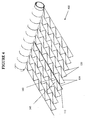
Figure 1 illustrates an isometric view of a first embodiment of the present invention; -
Figure 2 illustrates in detail, one option for forming loops in the longitudinal franzes of Raschel netting: -
Figure 3 illustrates a top view of a first embodiment of the present invention; -
Figures 4 and5 illustrate a second embodiment of the present invention, including a partially unrolled Raschel netting material with an added reflective strip alongside a longitudinal franze; -
Figure 6 illustrates a third embodiment of the present invention including reflective strips incorporated into the netting material alongside both the longitudinal franzes and zigzag schusses; -
Figure 7 is a photograph of the netting according to the third embodiment of the present invention taken with a flash; -
Figure 8 is a nighttime photograph of distant bales wrapped in the claimed netting material, where a reflective strip is used in a zigzag fashion; and -
Figure 9 is a photograph of the netting according to the third embodiment of the present invention taken without the use of a flash. - The present invention utilizes at least one reflective or luminescent strip which is incorporated into Raschel netting material, used to bale crops Raschel knitted netting is known from
U.S. Patent Nos. 5,104,714 and6,521,551 . - In the embodiments described herein, the reflective or luminescent strip is added to the net alongside a least one of the longitudinal ribbons or at least one of the substantially transverse or lateral ribbons or both. The longitudinal and substantially lateral ribbons are respectively referred to as franzes and schusses.
- In other embodiments described hereinafter, the reflective strips can extend the entire length of the netting or can extend for a predetermined part of the netting on a roll. Additionally, the reflective or luminescent strips may themselves have a predetermined color that is visible during the day and/or the night.
- Because the strip tends to twist while being knitted into the roll of net and while the net is being used, a preferred type of strip is reflective or luminescent on both faces.
- Depending on the specific embodiment, the reflective/luminescent strip can be incorporated into the net for a predetermined length, providing a warning for the last 100 linear meters of net, an amount sufficient for wrapping about 8 bales, or any other length that could be desired.
- Since a bale itself cannot usually be seen at night unless the operator drives by it, at least one reflective/luminescent marker may be inserted along the entire length of the net in order to increase low- or reduced- light visibility of every bale that may be on a field. For example, reflective/luminescent markers can be located adjacent to the lateral side(s) of the netting, adjacent to the centre, or any location.
- In a test performed by applicants, it was found that when a tractor's lights fall on a bale having a reflective strip, the bale can be seen even from a distance of 50 metres, and in some conditions even from a distance of 100 metres. In such conditions, the operator may notice the bale even if it is across a field.
- Alternatively, netting can be provided with at least one reflective/luminescent marker along the entire length of the net, with a second reflective/luminescent marker only at the end of the net serving as a roll-end marker.
- The invention will now be described with reference to the drawing figures.
Figures 1 and3 illustrate a first embodiment of the present invention in isometric and top views, respectively.Figures 1 and3 show a partially unrolledRaschel netting material 100, in which areflective strip 110 has been added to thenetting 100. In this embodiment, thereflective strip 110 is inserted into the net adjacent to one of the zigzag schusses 120. Thelongitudinal franzes 130 are shown. Thereflective strip 110 is threaded into the netting material such that at itsapexes 115, it only passes through theapertures franze 130 at that point. Alternatively, thereflective strip 110 is threaded or knitted into the nettingmaterial 100 in such a manner that it passes throughapertures 230, 250 (described below in connection withFigure 2 ) which are an integral part of thelongitudinal franzes 130. AlthoughFigures 1 and3 illustrate the use of a singlereflective strip 110, more than one reflective strip, at any desired position across the netting can be used. -
Figure 2 illustrates in more detail, how theloops longitudinal franzes 130 of Raschel netting 100 are formed. A single strand ofmaterial 210 is used to form the entire franze. Since only a segment is shown inFigure 2 , each end of the segment is shown as terminating in asingle strand 210 and in aloop 220 from an adjacent segment, but theseloops 220 occur at regular intervals throughout the length of thefranze 130, and createlinks 240. Theselinks 240 separateadjacent apertures 230, and provide a secure location through which to loop schusses 120, preventing the schusses from sliding along thefranzes 130. In this embodiment, theschuss 120 passes through theapertures 230. In a similar manner, thereflective strip 110 may be secured to thefranzes 130. As can be seen, it would also be possible to utilizeapertures 250 to secure theschuss 120 orreflective strip 110. - Still referring to
Figures 1-3 , since the purpose of using thereflective strip 110 is precisely for that reason, that is, for reflecting light, the strength of the reflective strip is not important if it is included in thenetting material 100 in an accessory capacity. Further, if included alongsideschusses 120, the strength is even less important, since most internal stresses in the netting material are experienced as tension in thelongitudinal franzes 130. -
Figures 4 and5 illustrate a second embodiment of the present invention. As shown, a partially unrolledRaschel netting material 400, includes an addedreflective strip 112 alongside alongitudinal franze 130. Thereflective strip 112 in this embodiment may be threaded along and around thefranze 130 throughapertures apertures Figures 1-3 , more than one franze ribbon may be replaced and/or supplemented with a reflective strip. - In both first and second embodiments illustrated in
Figures 1-3 and4-5 , as well as in the below-described embodiments, thereflective strip material -
Figure 6 illustrates a third embodiment of the present invention in whichreflective strips material 600 alongside both the longitudinal franzes 130 andzigzag schusses 120. The manners in which thereflective strips netting material 600 are the same as described in the first and second embodiments, respectively. - However, it is not necessary for both the schuss
reflective strip 110 and the franzereflective strip 112 to be inserted into the netting material in the same manner. For example, onereflective strip reflective strip 112 can be inserted by knitting directly into the nettingmaterial 600. -
Figure 7 is a photograph of the netting 860 according to the third embodiment of the present invention taken with a flash. In this embodiment, thereflective strip 110 is included adjacent to thestandard schuss 120, as in the first embodiment shown inFigures 1 and3 . In this version of the netting material 860, fourcoloured franzes 830 and onereflective strip 110 are provided. As shown inFigures 8 and9 , theseindicator sections 850, 950 are centrally located relative to the width of the net 860, however this placement is not required, and the indicator sections 850, 860, may be placed anywhere; near one edge or along both edges, for example. -
Figure 8 is a nighttime photograph of distant bales wrapped in the claimed netting material, where areflective strip 110 is used in a zigzag fashion, as shown inFigures 1 ,3 and7 . As seen in this photograph, which was taken using a camera flash, thenearest bales reflective strip 110. However, one can also see bales further from thephotographer -
Figure 9 is a photograph of the netting 860 according to the third embodiment of the present invention taken without use of a flash. As with the netting 860 inFigure 7 , thereflective strip 110 is included adjacent to thestandard schuss 120, also as in the first embodiment shown inFigures 1 and3 . In this version of the netting material 860, fourcoloured franzes 830 and onereflective strip 110 are provided. In comparison withFigure 7 , a photograph of the same piece of netting but with use of a flash, the need for a secondary indicator (such as coloured franzes 830) in daylight is easily seen. The photograph ofFigure 9 (without a flash), does not show great contrast between thereflective strip 110 and the rest of the netting material 860. With a flash (Figure 7 ), however the distinction is clear. Accordingly, it may be desirable in some instances to use bothreflective strips 110 and coloured ribbons in coloured franzes or schusses. - In all embodiments, the
schusses 120 and franzes 130 and strips 110, 112 can be manufactured out of many materials, including, not limited to polymeric materials, such as polypropylene, polyethylene, polyester, polyethylene terephthalate, nylon, polyvinyl chloride. Also, the thread, ribbon or strips comprising theschusses 120,franzes 130, andreflective strips - In many embodiments, reflective and/or coloured elements are provided as an indicator for approximately the last 100 linear metres of net, which is enough material for approximately 8 bales. As an alternative, the roll-end indicator may have additional features, such as colour or pattern-changing as the roll end approaches. For example, the first roll end indicator seen (e.g., 100-80 metres from the end of the net) can have a yellow tinge, which can change as netting continues to be dispensed to orange and/or red as the net end approaches. In such instance, the operator would be aware that the net end is approaching when he sees yellow, but would know that by the time red is seen, there is only enough netting material for at most one more bale. As such, material need not be wasted by discarding unused net. This general concept of the roll-end indicator can be applied to nonreflective indicators as well, where the colour changes as the roll end approaches. Further, this variation can also be used in combination with a continuous reflective marker throughout the length of the net.
- When wound on a spool or core, the roll end is the portion of net closest to the core. Accordingly, during manufacture, this section can be prepared first and wound onto the core, with the remainder of the netting material being manufactured in a conventional manner and wound on the core over the reflective portions.
- When a reflective material is used as the mark, the reflective material has a coefficient of retroreflection (RA), in the range of 30 to 700, for example 250. Marker tensile strengths on the order of 140-800 grams are contemplated. Similarly, materials used as a marker can have elongation between 0% and 200%, for example 10%, 20%, 30%, 40%, 50%, 60% etc. In addition, the marker material can have the same or different elongation properties that those of the franze or schuss ribbon that it replaces or supplements. A reflective material can include polymeric material that is made reflective by the addition of refractive particles, such as very small beads formed from glass or polymeric materials.
- Further, the reflective material may have any suitable width such as between 1/69 inch and 10 inches, for example 1/69 inch, 1/32 inch or 1/23 inch.
- As discussed herein netting material, can incorporate the reflective indicator throughout the entire length of the netting material so that any bale wrapped with the material is visible at night.
- In other embodiments the subject netting material incorporates a first reflective indicator throughout the entire length of the netting material, and a second reflective indicator at the end of the netting material. In this case, the first reflective indicator allows any bale wrapped with the material to be visible at night, while the second indicator allows an operator to be alerted to an approaching end of the netting material. In such a case, the first and second reflective indicators would necessarily be distinguishable. Such distinction can be achieved by providing a separate or different pattern and/or colour for each indicator, or even simply placing the reflective indicators at different positions on the net. For example, a first indicator can be arranged in the middle of the net, with the second indicator being arranged toward one edge of the net, or vice versa. Of course, this alternative embodiment may also include coloured netting elements to alert an operator to an approaching roll end in daylight.
- A further alternate means of distinguishing between a continuous (throughout the entire net length) indicator and a roll end indicator incorporates a single strand of indicator material. Such indicator itself can vary in colour or pattern throughout its length to indicate whether the end of netting material is approaching. For example, the indicator material may be solid for a majority of its length, but in the region where roll-end indication is desired, the reflectivity of the reflective strand can be varied. That is, what is otherwise a "solid" reflective strand can become an intermittently reflective strand. This can be achieved by obscuring intermittent portions of the reflective strand with opaque paint or the like.
- While netting may be initially manufactured to incorporate a reflective indicator, such indicator may be incorporated into a roll that has already been manufactured. If an existing roll of netting is to be modified, it is possible to incorporate a reflective marker into the net, and wind the net onto another spool or core.
- While the above embodiments include a reflective and/or coloured roll-end indicator that is integrated into the netting material in a substantially longitudinal direction, it is possible to include markers that are arranged in a substantially transverse manner. For example, rather than incorporating a zigzag reflective schuss, segments of reflective strips along the width of the netting can be inserted intermittently along the length of the netting, perpendicular to a longitudinal axis of the netting material. This alternative means of reflective indication can communicate information to an operator in a variety of manners. For example, different colour reflective materials can be used as the roll end approaches and/or the frequency of transverse reflective indicators can be increased, placed adjacent to each other in pairs, threes, and so on.
- A further variation of the subject reflective and/or coloured indicators provides different coloured and/or patterned indicators for different crops. As a result, if stored in a dark barn or in a field, a baled crop can be quickly and easily identified.
- It is to be understood that the term "reflective" has been used above to describe the type of marker preferred for the present invention, that a luminescent marker may be substituted in its place. Such luminescent markers may include so-called"glow in the dark" materials. Further materials having a fluorescent colour that is easily viewable in poor lighting conditions may also be used.
- It is to be understood that other embodiments utilizing the subject reflective markers and falling within the scope of the appended claims are possible.
Claims (24)
- A netting comprising knitted longitudinal franze ribbons (130) and interconnecting transverse schuss ribbons (120) that zigzag laterally between the adjacent longitudinal franze ribbons (130) and form a series of triangular openings (140,145), characterised by at least one reflective or luminescent indicator strip (110,112) that is threaded or knitted into the netting so as to extend over at least a part of the length of the netting adjacent to at least one of the longitudinal franze ribbons (130), at least one of the interconnecting zigzag schuss ribbons (120), or both.
- The netting of claim 1, wherein the at least one reflective indicator strip (110) extends from an end of the netting along a longitudinal direction of the netting.
- The netting of claim 1 or claim 2, wherein a plurality of said openings (140,145) are formed from the longitudinal franze ribbons (130) and the interconnecting transverse schuss ribbons (120).
- The netting of claim 3, wherein the at least one reflective indicator strip (110,112) is arranged adjacent to one of the longitudinal franze ribbons (130) and extends through the opening (140,145).
- The netting of claim 3, wherein the at least one reflective indicator strip (110,112) is arranged adjacent to one of the transverse schuss ribbons (120) and extends through the openings (140,145).
- The netting of any preceding claim, wherein the at least one reflective indicator strip (110,112) extends over the entire length of the netting.
- The netting of any of claims 1 to 5, wherein the at least one indicator strip (110,112) extends over a part of the netting length.
- The netting of any preceding claim, wherein the at least one reflective indicator strip (110,112) is located continuously between an end of the netting and a point spaced a predetermined distance from the end, thereby acting as a visual signal to a user that an end of the netting is approaching.
- A netting according to any preceding claim, wherein the reflective indicator strip (110,112) has first and second faces and comprises reflective material on both faces.
- The netting according to any of claims 1 to 8, wherein the reflective indicator strip (110,112) has first and second faces and comprises reflective material only on one face.
- The netting according to any preceding claim, wherein the reflective indicator strip (110,112) comprises a polymeric material.
- The netting according to any preceding claim, wherein a substrate of the reflective indicator strip (110,112) is made reflective by the addition of refractive particles.
- The netting according to claim 3, wherein the refractive particles are very small glass beads.
- The netting according to any preceding claim, wherein the at least one reflective indicator strip (110,112) includes first and second reflective indicator strips arranged on the netting material in different patterns to facilitate distinction between the indicator strips.
- The netting material of any preceding claim, wherein the at least one reflective indicator strip (110,112) includes first and second reflective indicator strips arranged on the netting in different locations relative to a centre line of the netting material to facilitate distinction between the indicator strips (110,112).
- The netting according to any preceding claim, wherein the at least one indicator strip (110,112) includes first and second reflective indicator strips of different colours to facilitate distinction between the indicator strips (110,112).
- The netting according to any preceding claim, wherein said at least one reflective indicator strip (110,112) has a retroreflective value of at least 30, said reflective indicator strip (110,112) identifying at least one of an approaching end of the knitted netting and a boundary of the knitted netting.
- A netting according to any preceding claim formed into a roll.
- A round bale wrapped about its circumference with the netting of any one of claims 1-17.
- A method of wrapping a bale of agricultural produce in a baler comprising supplying a baling machine with a roll of knitted netting according to claim 1, wherein said at least one reflective indicator strip (110,112) extends longitudinally continuously from one end of the netting material to a point located at a predetermined distance from said one end, the at least one reflective indicator strip (110,112) alerting a user that an end of the netting material is approaching and, wrapping said bale in said netting using said baling machine.
- A method of providing a reflective netting comprising:(a) providing a knitted netting having longitudinal franze ribbons (130) and inteconnecting transverse schuss ribbons (120) that
zigzag laterally between adjacent longitudinal franze ribbons (130) and form a series of triangular openings (140,145); and(b) threading or knitting at least one reflective or luminescent indicator strip (110,112) into the netting so as to extend over at least a part of the length of the netting adjacent to at least one ofthe longitudinal franze ribbons (130) and/or the interconnecting zigzag schuss ribbons (120). - The method of claim 21, wherein the method includes the step of threading at least one reflective indicator strip (110,112)through the series of triangular openings along at least a portion of said netting length.
- The method of claim 22, wherein the method includes the step of threading at least one reflective indicator strip (110,112) through loops (220) in the longitudinal franze ribbons (130) along at least a portion of said netting length.
- The method of claim 23, wherein the at least a portion of the netting length is the entire length of the netting.
Applications Claiming Priority (1)
| Application Number | Priority Date | Filing Date | Title |
|---|---|---|---|
| PCT/IB2004/002908 WO2006027637A1 (en) | 2004-09-07 | 2004-09-07 | Netting material with reflective or luminescent marker |
Publications (2)
| Publication Number | Publication Date |
|---|---|
| EP1786964A1 EP1786964A1 (en) | 2007-05-23 |
| EP1786964B1 true EP1786964B1 (en) | 2008-08-20 |
Family
ID=34958681
Family Applications (1)
| Application Number | Title | Priority Date | Filing Date |
|---|---|---|---|
| EP04769307A Expired - Lifetime EP1786964B1 (en) | 2004-09-07 | 2004-09-07 | Netting material with reflective or luminescent marker |
Country Status (10)
| Country | Link |
|---|---|
| US (1) | US20070021018A1 (en) |
| EP (1) | EP1786964B1 (en) |
| AT (1) | ATE405698T1 (en) |
| AU (1) | AU2004323107B2 (en) |
| CA (1) | CA2579437C (en) |
| DE (1) | DE602004016056D1 (en) |
| ES (1) | ES2313064T3 (en) |
| NZ (1) | NZ553845A (en) |
| PT (1) | PT1786964E (en) |
| WO (1) | WO2006027637A1 (en) |
Families Citing this family (8)
| Publication number | Priority date | Publication date | Assignee | Title |
|---|---|---|---|---|
| KR100900186B1 (en) * | 2008-07-23 | 2009-06-02 | 주식회사 대양 | Tag device of ratchet knitting machine |
| AU2010237076B2 (en) | 2009-04-16 | 2016-01-21 | Nine Ip Limited | Reflective netting material |
| CN103628239A (en) * | 2012-08-21 | 2014-03-12 | 东丽纤维研究所(中国)有限公司 | Cool sweat-absorbent quick-drying knitted fabric and application thereof |
| NL2015127B1 (en) | 2015-07-09 | 2017-02-01 | Forage Innovations Bv | Bale forming and wrapping apparatus with a web detecting sensor. |
| CN107916485B (en) * | 2017-12-19 | 2023-03-21 | 瑞安市超扬新材料科技有限公司 | Grass-wrapping net with weft lengthening design and manufacturing process thereof |
| PT110606B (en) | 2018-03-05 | 2021-02-05 | Cotesi - Companhia De Têxteis Sintéticos, S.A. | AGRICULTURAL MESH FOR BALING. |
| US11587313B2 (en) * | 2020-08-27 | 2023-02-21 | Deere & Company | Bale identification using photographic image of twine pattern |
| IT202300013959A1 (en) * | 2023-07-04 | 2025-01-04 | Tenax Spa | ROLL, PROCEDURE FOR THE CREATION OF SAID ROLL AND PROCEDURE FOR INSTALLING A NETWORK STRUCTURE |
Family Cites Families (20)
| Publication number | Priority date | Publication date | Assignee | Title |
|---|---|---|---|---|
| DE7808280U1 (en) * | 1978-03-18 | 1978-06-29 | Polydress Plastic Gmbh | bag |
| US4348312A (en) * | 1978-11-20 | 1982-09-07 | Minnesota Mining And Manufacturing Company | Ultra-high-index glass microspheres and products made therefrom with a fluoropolymer and an ester polymer blend |
| US4697407A (en) * | 1980-03-24 | 1987-10-06 | Minnesota Mining And Manufacturing Company | Retroreflective fiber and method of making same |
| DE3227160C3 (en) | 1982-07-21 | 1995-03-23 | Claas Ohg | Rolled bales from agricultural stalks |
| DE8311900U1 (en) * | 1983-04-22 | 1983-10-06 | Polydress Plastic Gmbh, 6120 Michelstadt | Bales of straw or hay |
| DD260819A3 (en) * | 1986-09-04 | 1988-10-12 | Heidenau Netz & Seil Veb | REFLECTIVE MATTRESS FOR GEWAECHSHAEUSER |
| US4901663A (en) * | 1988-06-13 | 1990-02-20 | Georgia-Pacific Corporation | Method of indicating towel roll depletion |
| US4957335A (en) * | 1989-05-26 | 1990-09-18 | Minnesota Mining And Manufacturing Company | Microsphere-based retroreflective articles with enhanced retroreflective brightness |
| US5104714A (en) | 1989-11-30 | 1992-04-14 | Tama Plastic Industry | Elastic plastic netting made of oriented strands |
| US5135568A (en) * | 1991-01-30 | 1992-08-04 | Rohm And Haas Company | Method for improving fluorescent coatings |
| NZ247432A (en) | 1992-07-09 | 1994-10-26 | Tama Plastic Ind | Forming knitted net from coloured ribbons |
| JP3461882B2 (en) * | 1993-11-27 | 2003-10-27 | ツネフヂ株式会社 | Textile product mixed with reflective yarn and reflection tool using fiber product mixed with reflective yarn |
| US5885686A (en) * | 1994-08-26 | 1999-03-23 | Leucadia, Inc. | Bicomponent elastomeric netting |
| AU7958794A (en) * | 1994-09-26 | 1996-04-19 | Polysack Plastic Industries Nir Itzhak-Sufa | Light reflecting screen |
| CA2251235C (en) | 1997-11-25 | 2006-09-05 | Yuval Leiber | Modified shuss knitted netting |
| US6660378B2 (en) * | 1998-04-23 | 2003-12-09 | Aspen Pet Products, Inc. | Glow-in-the-dark animal tie-out |
| WO2001016223A1 (en) * | 1999-09-02 | 2001-03-08 | Visibility Enhancement Technologies | Retroreflective inks and fabrics |
| US20020102389A1 (en) * | 2000-12-01 | 2002-08-01 | Nielsen Steven M. | Retroreflective laminate comprising a tear resistant film |
| US6948446B2 (en) * | 2003-06-18 | 2005-09-27 | Rts, Llc | Reflective arrowhead traffic sign apparatus |
| US6925965B1 (en) * | 2004-07-28 | 2005-08-09 | Nite Glow Industries, Inc. | Omnidirectional reflective pet leash |
-
2004
- 2004-09-07 DE DE602004016056T patent/DE602004016056D1/en not_active Expired - Lifetime
- 2004-09-07 CA CA2579437A patent/CA2579437C/en not_active Expired - Fee Related
- 2004-09-07 AU AU2004323107A patent/AU2004323107B2/en not_active Ceased
- 2004-09-07 EP EP04769307A patent/EP1786964B1/en not_active Expired - Lifetime
- 2004-09-07 PT PT04769307T patent/PT1786964E/en unknown
- 2004-09-07 ES ES04769307T patent/ES2313064T3/en not_active Expired - Lifetime
- 2004-09-07 US US10/516,830 patent/US20070021018A1/en not_active Abandoned
- 2004-09-07 NZ NZ553845A patent/NZ553845A/en not_active IP Right Cessation
- 2004-09-07 AT AT04769307T patent/ATE405698T1/en not_active IP Right Cessation
- 2004-09-07 WO PCT/IB2004/002908 patent/WO2006027637A1/en not_active Ceased
Also Published As
| Publication number | Publication date |
|---|---|
| WO2006027637A1 (en) | 2006-03-16 |
| WO2006027637A9 (en) | 2007-04-12 |
| AU2004323107B2 (en) | 2010-10-14 |
| ES2313064T3 (en) | 2009-03-01 |
| PT1786964E (en) | 2008-09-09 |
| AU2004323107A1 (en) | 2006-03-16 |
| NZ553845A (en) | 2010-02-26 |
| ATE405698T1 (en) | 2008-09-15 |
| EP1786964A1 (en) | 2007-05-23 |
| CA2579437C (en) | 2011-04-05 |
| US20070021018A1 (en) | 2007-01-25 |
| CA2579437A1 (en) | 2006-03-16 |
| DE602004016056D1 (en) | 2008-10-02 |
Similar Documents
| Publication | Publication Date | Title |
|---|---|---|
| AU2004323107B2 (en) | Netting material with reflective or luminescent marker | |
| ES2350632T3 (en) | WOVEN BELT MESH. | |
| EP0876809B1 (en) | Bandage compression indicator | |
| EP2710181B1 (en) | Netting with elongation indicator and method of determining the elongation of netting | |
| CA2966854C (en) | Strain sensing cable tie | |
| CA2582518A1 (en) | Method and apparatus for ice fishing | |
| JP3808351B2 (en) | fastener | |
| US5983949A (en) | Non-alpha-numeric coding of long flexible items | |
| US7461500B2 (en) | System for determining wear to rigging system lines | |
| EP0856248B1 (en) | Mistie detector system for agricultural balers. | |
| DE102007021300A1 (en) | Monitoring device for a sewing thread wound on a thread bobbin during a sewing machine operation, comprises an arrangement for monitoring a fill level of the bobbin and an optoelectric arrangement for a binary decision | |
| CA2962875C (en) | Net with identification and traceability system | |
| US20190257008A1 (en) | Warning indicator used for tie down straps-slings-slings | |
| IL175040A (en) | Durable knitted net | |
| JPH1132633A (en) | Fishing line provided with marker exhibiting feed-out length | |
| KR20120031850A (en) | Union net of circular baler | |
| WO2025169026A1 (en) | Net segment for round balers | |
| KR0156002B1 (en) | The automatic device for fishing squids | |
| JPH1026267A (en) | Hose with length information | |
| JPH072488U (en) | Interval display thread net | |
| KR950009301Y1 (en) | Cut-off detection device of slope preparation process | |
| JP2006081543A (en) | Luminous fishing gut, method for producing the same, and luminous main fishing line | |
| JP3029599U (en) | Fishing line | |
| AU2009101078A4 (en) | Tie-down strapping | |
| CN103481651A (en) | Trademark printing machine and control method for preventing breakage of trademark tapes |
Legal Events
| Date | Code | Title | Description |
|---|---|---|---|
| PUAI | Public reference made under article 153(3) epc to a published international application that has entered the european phase |
Free format text: ORIGINAL CODE: 0009012 |
|
| 17P | Request for examination filed |
Effective date: 20070319 |
|
| AK | Designated contracting states |
Kind code of ref document: A1 Designated state(s): AT BE BG CH CY CZ DE DK EE ES FI FR GB GR HU IE IT LI LU MC NL PL PT RO SE SI SK TR |
|
| AX | Request for extension of the european patent |
Extension state: AL HR LV MK |
|
| RAX | Requested extension states of the european patent have changed |
Extension state: MK Payment date: 20070319 Extension state: LT Payment date: 20070419 Extension state: LV Payment date: 20070319 Extension state: AL Payment date: 20070319 Extension state: HR Payment date: 20070319 |
|
| 17Q | First examination report despatched |
Effective date: 20070719 |
|
| GRAP | Despatch of communication of intention to grant a patent |
Free format text: ORIGINAL CODE: EPIDOSNIGR1 |
|
| GRAS | Grant fee paid |
Free format text: ORIGINAL CODE: EPIDOSNIGR3 |
|
| GRAA | (expected) grant |
Free format text: ORIGINAL CODE: 0009210 |
|
| AK | Designated contracting states |
Kind code of ref document: B1 Designated state(s): AT BE BG CH CY CZ DE DK EE ES FI FR GB GR HU IE IT LI LU MC NL PL PT RO SE SI SK TR |
|
| AX | Request for extension of the european patent |
Extension state: AL HR LT LV MK |
|
| REG | Reference to a national code |
Ref country code: GB Ref legal event code: FG4D |
|
| REG | Reference to a national code |
Ref country code: CH Ref legal event code: EP |
|
| REG | Reference to a national code |
Ref country code: PT Ref legal event code: SC4A Free format text: AVAILABILITY OF NATIONAL TRANSLATION Effective date: 20080828 |
|
| REG | Reference to a national code |
Ref country code: IE Ref legal event code: FG4D |
|
| REF | Corresponds to: |
Ref document number: 602004016056 Country of ref document: DE Date of ref document: 20081002 Kind code of ref document: P |
|
| REG | Reference to a national code |
Ref country code: SE Ref legal event code: TRGR |
|
| REG | Reference to a national code |
Ref country code: GR Ref legal event code: EP Ref document number: 20080402747 Country of ref document: GR |
|
| LTIE | Lt: invalidation of european patent or patent extension |
Effective date: 20080820 |
|
| PG25 | Lapsed in a contracting state [announced via postgrant information from national office to epo] |
Ref country code: NL Free format text: LAPSE BECAUSE OF FAILURE TO SUBMIT A TRANSLATION OF THE DESCRIPTION OR TO PAY THE FEE WITHIN THE PRESCRIBED TIME-LIMIT Effective date: 20080820 |
|
| PG25 | Lapsed in a contracting state [announced via postgrant information from national office to epo] |
Ref country code: AT Free format text: LAPSE BECAUSE OF FAILURE TO SUBMIT A TRANSLATION OF THE DESCRIPTION OR TO PAY THE FEE WITHIN THE PRESCRIBED TIME-LIMIT Effective date: 20080820 Ref country code: FI Free format text: LAPSE BECAUSE OF FAILURE TO SUBMIT A TRANSLATION OF THE DESCRIPTION OR TO PAY THE FEE WITHIN THE PRESCRIBED TIME-LIMIT Effective date: 20080820 Ref country code: SI Free format text: LAPSE BECAUSE OF FAILURE TO SUBMIT A TRANSLATION OF THE DESCRIPTION OR TO PAY THE FEE WITHIN THE PRESCRIBED TIME-LIMIT Effective date: 20080820 |
|
| REG | Reference to a national code |
Ref country code: ES Ref legal event code: FG2A Ref document number: 2313064 Country of ref document: ES Kind code of ref document: T3 |
|
| PG25 | Lapsed in a contracting state [announced via postgrant information from national office to epo] |
Ref country code: BE Free format text: LAPSE BECAUSE OF FAILURE TO SUBMIT A TRANSLATION OF THE DESCRIPTION OR TO PAY THE FEE WITHIN THE PRESCRIBED TIME-LIMIT Effective date: 20080820 |
|
| PG25 | Lapsed in a contracting state [announced via postgrant information from national office to epo] |
Ref country code: MC Free format text: LAPSE BECAUSE OF NON-PAYMENT OF DUE FEES Effective date: 20080930 Ref country code: DK Free format text: LAPSE BECAUSE OF FAILURE TO SUBMIT A TRANSLATION OF THE DESCRIPTION OR TO PAY THE FEE WITHIN THE PRESCRIBED TIME-LIMIT Effective date: 20080820 Ref country code: BG Free format text: LAPSE BECAUSE OF FAILURE TO SUBMIT A TRANSLATION OF THE DESCRIPTION OR TO PAY THE FEE WITHIN THE PRESCRIBED TIME-LIMIT Effective date: 20081120 |
|
| REG | Reference to a national code |
Ref country code: CH Ref legal event code: PL |
|
| PG25 | Lapsed in a contracting state [announced via postgrant information from national office to epo] |
Ref country code: RO Free format text: LAPSE BECAUSE OF FAILURE TO SUBMIT A TRANSLATION OF THE DESCRIPTION OR TO PAY THE FEE WITHIN THE PRESCRIBED TIME-LIMIT Effective date: 20080820 Ref country code: SK Free format text: LAPSE BECAUSE OF FAILURE TO SUBMIT A TRANSLATION OF THE DESCRIPTION OR TO PAY THE FEE WITHIN THE PRESCRIBED TIME-LIMIT Effective date: 20080820 Ref country code: CZ Free format text: LAPSE BECAUSE OF FAILURE TO SUBMIT A TRANSLATION OF THE DESCRIPTION OR TO PAY THE FEE WITHIN THE PRESCRIBED TIME-LIMIT Effective date: 20080820 |
|
| PLBE | No opposition filed within time limit |
Free format text: ORIGINAL CODE: 0009261 |
|
| STAA | Information on the status of an ep patent application or granted ep patent |
Free format text: STATUS: NO OPPOSITION FILED WITHIN TIME LIMIT |
|
| 26N | No opposition filed |
Effective date: 20090525 |
|
| PG25 | Lapsed in a contracting state [announced via postgrant information from national office to epo] |
Ref country code: EE Free format text: LAPSE BECAUSE OF FAILURE TO SUBMIT A TRANSLATION OF THE DESCRIPTION OR TO PAY THE FEE WITHIN THE PRESCRIBED TIME-LIMIT Effective date: 20080820 |
|
| PG25 | Lapsed in a contracting state [announced via postgrant information from national office to epo] |
Ref country code: LI Free format text: LAPSE BECAUSE OF NON-PAYMENT OF DUE FEES Effective date: 20080930 Ref country code: CH Free format text: LAPSE BECAUSE OF NON-PAYMENT OF DUE FEES Effective date: 20080930 |
|
| PG25 | Lapsed in a contracting state [announced via postgrant information from national office to epo] |
Ref country code: PL Free format text: LAPSE BECAUSE OF FAILURE TO SUBMIT A TRANSLATION OF THE DESCRIPTION OR TO PAY THE FEE WITHIN THE PRESCRIBED TIME-LIMIT Effective date: 20080820 |
|
| PG25 | Lapsed in a contracting state [announced via postgrant information from national office to epo] |
Ref country code: HU Free format text: LAPSE BECAUSE OF FAILURE TO SUBMIT A TRANSLATION OF THE DESCRIPTION OR TO PAY THE FEE WITHIN THE PRESCRIBED TIME-LIMIT Effective date: 20090221 Ref country code: LU Free format text: LAPSE BECAUSE OF NON-PAYMENT OF DUE FEES Effective date: 20080907 Ref country code: CY Free format text: LAPSE BECAUSE OF FAILURE TO SUBMIT A TRANSLATION OF THE DESCRIPTION OR TO PAY THE FEE WITHIN THE PRESCRIBED TIME-LIMIT Effective date: 20080820 |
|
| PG25 | Lapsed in a contracting state [announced via postgrant information from national office to epo] |
Ref country code: TR Free format text: LAPSE BECAUSE OF FAILURE TO SUBMIT A TRANSLATION OF THE DESCRIPTION OR TO PAY THE FEE WITHIN THE PRESCRIBED TIME-LIMIT Effective date: 20080820 |
|
| PGFP | Annual fee paid to national office [announced via postgrant information from national office to epo] |
Ref country code: SE Payment date: 20130911 Year of fee payment: 10 Ref country code: IE Payment date: 20130910 Year of fee payment: 10 Ref country code: ES Payment date: 20130813 Year of fee payment: 10 Ref country code: DE Payment date: 20130904 Year of fee payment: 10 Ref country code: PT Payment date: 20130308 Year of fee payment: 10 Ref country code: GR Payment date: 20130813 Year of fee payment: 10 |
|
| PGFP | Annual fee paid to national office [announced via postgrant information from national office to epo] |
Ref country code: GB Payment date: 20130904 Year of fee payment: 10 Ref country code: FR Payment date: 20130910 Year of fee payment: 10 |
|
| PGFP | Annual fee paid to national office [announced via postgrant information from national office to epo] |
Ref country code: IT Payment date: 20130909 Year of fee payment: 10 |
|
| REG | Reference to a national code |
Ref country code: DE Ref legal event code: R082 Ref document number: 602004016056 Country of ref document: DE Representative=s name: VENNER SHIPLEY LLP, GB |
|
| REG | Reference to a national code |
Ref country code: PT Ref legal event code: MM4A Free format text: LAPSE DUE TO NON-PAYMENT OF FEES Effective date: 20150309 |
|
| REG | Reference to a national code |
Ref country code: DE Ref legal event code: R119 Ref document number: 602004016056 Country of ref document: DE |
|
| PG25 | Lapsed in a contracting state [announced via postgrant information from national office to epo] |
Ref country code: PT Free format text: LAPSE BECAUSE OF NON-PAYMENT OF DUE FEES Effective date: 20150309 |
|
| REG | Reference to a national code |
Ref country code: SE Ref legal event code: EUG |
|
| REG | Reference to a national code |
Ref country code: GR Ref legal event code: ML Ref document number: 20080402747 Country of ref document: GR Effective date: 20150403 |
|
| GBPC | Gb: european patent ceased through non-payment of renewal fee |
Effective date: 20140907 |
|
| PG25 | Lapsed in a contracting state [announced via postgrant information from national office to epo] |
Ref country code: SE Free format text: LAPSE BECAUSE OF NON-PAYMENT OF DUE FEES Effective date: 20140908 |
|
| REG | Reference to a national code |
Ref country code: DE Ref legal event code: R119 Ref document number: 602004016056 Country of ref document: DE Effective date: 20150401 |
|
| REG | Reference to a national code |
Ref country code: FR Ref legal event code: ST Effective date: 20150529 |
|
| PG25 | Lapsed in a contracting state [announced via postgrant information from national office to epo] |
Ref country code: GB Free format text: LAPSE BECAUSE OF NON-PAYMENT OF DUE FEES Effective date: 20140907 Ref country code: DE Free format text: LAPSE BECAUSE OF NON-PAYMENT OF DUE FEES Effective date: 20150401 |
|
| PG25 | Lapsed in a contracting state [announced via postgrant information from national office to epo] |
Ref country code: FR Free format text: LAPSE BECAUSE OF NON-PAYMENT OF DUE FEES Effective date: 20140930 Ref country code: GR Free format text: LAPSE BECAUSE OF NON-PAYMENT OF DUE FEES Effective date: 20150403 Ref country code: IT Free format text: LAPSE BECAUSE OF NON-PAYMENT OF DUE FEES Effective date: 20140907 |
|
| REG | Reference to a national code |
Ref country code: ES Ref legal event code: FD2A Effective date: 20151127 |
|
| PG25 | Lapsed in a contracting state [announced via postgrant information from national office to epo] |
Ref country code: ES Free format text: LAPSE BECAUSE OF NON-PAYMENT OF DUE FEES Effective date: 20140908 |
|
| REG | Reference to a national code |
Ref country code: IE Ref legal event code: MM4A |
|
| PG25 | Lapsed in a contracting state [announced via postgrant information from national office to epo] |
Ref country code: IE Free format text: LAPSE BECAUSE OF NON-PAYMENT OF DUE FEES Effective date: 20140907 |