EP1786320B1 - Mri-systeme mit mri-kompatiblen universellen ablieferungskanülen mit kooperierenden mri-antennensonden und diesbezügliche systeme und verfahren - Google Patents
Mri-systeme mit mri-kompatiblen universellen ablieferungskanülen mit kooperierenden mri-antennensonden und diesbezügliche systeme und verfahren Download PDFInfo
- Publication number
- EP1786320B1 EP1786320B1 EP05775680.1A EP05775680A EP1786320B1 EP 1786320 B1 EP1786320 B1 EP 1786320B1 EP 05775680 A EP05775680 A EP 05775680A EP 1786320 B1 EP1786320 B1 EP 1786320B1
- Authority
- EP
- European Patent Office
- Prior art keywords
- mri
- antenna
- cannula
- probe
- probe system
- Prior art date
- Legal status (The legal status is an assumption and is not a legal conclusion. Google has not performed a legal analysis and makes no representation as to the accuracy of the status listed.)
- Active
Links
- 239000000523 sample Substances 0.000 title claims description 98
- 238000000034 method Methods 0.000 title description 12
- 241001631457 Cannula Species 0.000 title 1
- 230000000638 stimulation Effects 0.000 claims description 20
- 210000004556 brain Anatomy 0.000 claims description 11
- 230000005540 biological transmission Effects 0.000 claims description 6
- 230000005284 excitation Effects 0.000 claims description 5
- 239000004020 conductor Substances 0.000 claims description 4
- 238000001727 in vivo Methods 0.000 claims description 4
- 238000002595 magnetic resonance imaging Methods 0.000 description 95
- 210000001519 tissue Anatomy 0.000 description 19
- 238000012545 processing Methods 0.000 description 10
- 210000003484 anatomy Anatomy 0.000 description 9
- 238000003384 imaging method Methods 0.000 description 9
- 230000001537 neural effect Effects 0.000 description 8
- 239000000835 fiber Substances 0.000 description 7
- 230000006870 function Effects 0.000 description 7
- 238000003333 near-infrared imaging Methods 0.000 description 6
- 238000004891 communication Methods 0.000 description 5
- 210000003128 head Anatomy 0.000 description 5
- 239000000463 material Substances 0.000 description 5
- 241000288906 Primates Species 0.000 description 4
- 238000010586 diagram Methods 0.000 description 4
- 238000007917 intracranial administration Methods 0.000 description 4
- 238000005259 measurement Methods 0.000 description 4
- HLXZNVUGXRDIFK-UHFFFAOYSA-N nickel titanium Chemical compound [Ti].[Ti].[Ti].[Ti].[Ti].[Ti].[Ti].[Ti].[Ti].[Ti].[Ti].[Ni].[Ni].[Ni].[Ni].[Ni].[Ni].[Ni].[Ni].[Ni].[Ni].[Ni].[Ni].[Ni].[Ni] HLXZNVUGXRDIFK-UHFFFAOYSA-N 0.000 description 4
- 229910001000 nickel titanium Inorganic materials 0.000 description 4
- 210000004281 subthalamic nucleus Anatomy 0.000 description 4
- 241001465754 Metazoa Species 0.000 description 3
- 238000000576 coating method Methods 0.000 description 3
- 230000006872 improvement Effects 0.000 description 3
- 238000012986 modification Methods 0.000 description 3
- 230000004048 modification Effects 0.000 description 3
- 210000005036 nerve Anatomy 0.000 description 3
- 230000002889 sympathetic effect Effects 0.000 description 3
- 210000000115 thoracic cavity Anatomy 0.000 description 3
- FAPWRFPIFSIZLT-UHFFFAOYSA-M Sodium chloride Chemical compound [Na+].[Cl-] FAPWRFPIFSIZLT-UHFFFAOYSA-M 0.000 description 2
- 229940008201 allegra Drugs 0.000 description 2
- 238000001574 biopsy Methods 0.000 description 2
- 238000005253 cladding Methods 0.000 description 2
- 239000011248 coating agent Substances 0.000 description 2
- 230000001419 dependent effect Effects 0.000 description 2
- RWTNPBWLLIMQHL-UHFFFAOYSA-N fexofenadine Chemical compound C1=CC(C(C)(C(O)=O)C)=CC=C1C(O)CCCN1CCC(C(O)(C=2C=CC=CC=2)C=2C=CC=CC=2)CC1 RWTNPBWLLIMQHL-UHFFFAOYSA-N 0.000 description 2
- 238000002513 implantation Methods 0.000 description 2
- 238000011065 in-situ storage Methods 0.000 description 2
- 238000003780 insertion Methods 0.000 description 2
- 230000037431 insertion Effects 0.000 description 2
- 239000011780 sodium chloride Substances 0.000 description 2
- 239000007787 solid Substances 0.000 description 2
- 230000001225 therapeutic effect Effects 0.000 description 2
- 238000011282 treatment Methods 0.000 description 2
- 208000000094 Chronic Pain Diseases 0.000 description 1
- 208000014094 Dystonic disease Diseases 0.000 description 1
- 208000002193 Pain Diseases 0.000 description 1
- 208000018737 Parkinson disease Diseases 0.000 description 1
- 239000004642 Polyimide Substances 0.000 description 1
- 238000002679 ablation Methods 0.000 description 1
- 230000003213 activating effect Effects 0.000 description 1
- 230000002902 bimodal effect Effects 0.000 description 1
- 239000013060 biological fluid Substances 0.000 description 1
- 230000015572 biosynthetic process Effects 0.000 description 1
- 210000000746 body region Anatomy 0.000 description 1
- 238000004590 computer program Methods 0.000 description 1
- 238000013480 data collection Methods 0.000 description 1
- 238000013500 data storage Methods 0.000 description 1
- 230000008021 deposition Effects 0.000 description 1
- 238000001514 detection method Methods 0.000 description 1
- 229940079593 drug Drugs 0.000 description 1
- 239000003814 drug Substances 0.000 description 1
- 230000009977 dual effect Effects 0.000 description 1
- 208000010118 dystonia Diseases 0.000 description 1
- 201000006517 essential tremor Diseases 0.000 description 1
- 238000002474 experimental method Methods 0.000 description 1
- 238000000605 extraction Methods 0.000 description 1
- 239000012530 fluid Substances 0.000 description 1
- PCHJSUWPFVWCPO-UHFFFAOYSA-N gold Chemical compound [Au] PCHJSUWPFVWCPO-UHFFFAOYSA-N 0.000 description 1
- 239000010931 gold Substances 0.000 description 1
- 229910052737 gold Inorganic materials 0.000 description 1
- 239000007943 implant Substances 0.000 description 1
- 238000009413 insulation Methods 0.000 description 1
- 238000002955 isolation Methods 0.000 description 1
- WABPQHHGFIMREM-UHFFFAOYSA-N lead(0) Chemical compound [Pb] WABPQHHGFIMREM-UHFFFAOYSA-N 0.000 description 1
- 230000007246 mechanism Effects 0.000 description 1
- 210000003928 nasal cavity Anatomy 0.000 description 1
- 230000003287 optical effect Effects 0.000 description 1
- 239000011295 pitch Substances 0.000 description 1
- 229920002401 polyacrylamide Polymers 0.000 description 1
- 229920000728 polyester Polymers 0.000 description 1
- 229920001721 polyimide Polymers 0.000 description 1
- 239000004814 polyurethane Substances 0.000 description 1
- 229920002635 polyurethane Polymers 0.000 description 1
- 238000009781 safety test method Methods 0.000 description 1
- 210000003625 skull Anatomy 0.000 description 1
- 210000000278 spinal cord Anatomy 0.000 description 1
- 230000003068 static effect Effects 0.000 description 1
- 239000000758 substrate Substances 0.000 description 1
- 238000001356 surgical procedure Methods 0.000 description 1
- 238000012360 testing method Methods 0.000 description 1
- 238000002560 therapeutic procedure Methods 0.000 description 1
- 238000012546 transfer Methods 0.000 description 1
- 238000010200 validation analysis Methods 0.000 description 1
- 210000004885 white matter Anatomy 0.000 description 1
Images


Classifications
-
- A—HUMAN NECESSITIES
- A61—MEDICAL OR VETERINARY SCIENCE; HYGIENE
- A61B—DIAGNOSIS; SURGERY; IDENTIFICATION
- A61B5/00—Measuring for diagnostic purposes; Identification of persons
- A61B5/05—Detecting, measuring or recording for diagnosis by means of electric currents or magnetic fields; Measuring using microwaves or radio waves
- A61B5/055—Detecting, measuring or recording for diagnosis by means of electric currents or magnetic fields; Measuring using microwaves or radio waves involving electronic [EMR] or nuclear [NMR] magnetic resonance, e.g. magnetic resonance imaging
-
- A—HUMAN NECESSITIES
- A61—MEDICAL OR VETERINARY SCIENCE; HYGIENE
- A61B—DIAGNOSIS; SURGERY; IDENTIFICATION
- A61B5/00—Measuring for diagnostic purposes; Identification of persons
- A61B5/06—Devices, other than using radiation, for detecting or locating foreign bodies ; determining position of probes within or on the body of the patient
-
- G—PHYSICS
- G01—MEASURING; TESTING
- G01R—MEASURING ELECTRIC VARIABLES; MEASURING MAGNETIC VARIABLES
- G01R33/00—Arrangements or instruments for measuring magnetic variables
- G01R33/20—Arrangements or instruments for measuring magnetic variables involving magnetic resonance
- G01R33/28—Details of apparatus provided for in groups G01R33/44 - G01R33/64
- G01R33/285—Invasive instruments, e.g. catheters or biopsy needles, specially adapted for tracking, guiding or visualization by NMR
Definitions
- the present invention relates to medical leads and may be particularly suitable for use with MRI compatible medical instruments such as implantable Deep Brain Stimulation ("DBS”) leads and/or implantable sympathetic nerve chain stimulation leads.
- DBS Deep Brain Stimulation
- DBS Deep Brain Stimulation
- Other electro-stimulation therapies have also been carried out or proposed using internal stimulation of the sympathetic nerve chain and/or spinal cord, etc.
- the Activa® system includes an implantable pulse generator stimulator that is positioned in the chest cavity of the patient and a lead with axially spaced apart electrodes that is implanted with the electrodes disposed in neural tissue.
- the lead is tunneled subsurface from the brain to the chest cavity connecting the electrodes with the pulse generator.
- These leads can have multiple exposed electrodes at the distal end that are connected to conductors which run along the length of the lead and connect to the pulse generator placed in the chest cavity.
- electrostimulation is carried out by delivering a pulse of desired frequency and amplitude in the target cranial tissue, typically using an implanted lead system.
- lead systems have electrodes that are exposed at a distal end to contact the target cranial/neuronal tissue.
- the lead systems are connected to an implanted pulse generator at the other opposing end (proximal end).
- the distal end of the lead system is implanted in the desired cranial anatomy by stereotactic surgical procedures.
- a microelectrode system is advanced in the cranial tissue, typically based on MRI, CT or PET images acquired prior to the procedure.
- the target location for lead implantation in the cranial anatomy may be determined by measuring the electrical signal (EPG) signature of the specific anatomy using a microelectrode system.
- EPG electrical signal
- U.S. Patent Application Publication No. 2002/0045816 describes an apparatus for internally imaging using magnetic resonance imaging.
- the apparatus has a substantially tubular member with a detector coil attached in proximity to the distal end of the tubular member.
- the tubular member is placed coaxially inside a second tubular member and is slideably related to the second tubular member.
- Embodiments of the present invention are defined in claim 1 and in the dependent claims.
- Probe embodiments of the present invention can be configured to image, record and/or stimulate any desired internal region of the body or object.
- the object can be any object, and may be particularly suitable for animal and/or human subjects.
- Some probe embodiments can be sized and configured for deep brain interrogation.
- Some probe embodiments can be configured to place interventional devices to treat, such as stimulation electrodes to stimulate a desired region of the brain and/or sympathetic nerve chain. Examples of known stimulation treatments and/or target body regions are described in U.S. Patent Nos. 6,708,064 ; 6,438,423 ; 6,356,786 ; 6,526,318 ; 6,405,079 ; 6,167,311 ; 6539,263 ; 6,609,030 and 6,050,992 .
- Figure 1 illustrates a first embodiment of an MRI probe assembly 5 that can define an internal MRI antenna 51 according to the present invention.
- the assembly 5 comprises a plurality of generally concentric members, shown as three members 10,20,30.
- the outer member 30 and/or intermediate member 20 can be a cannula member 75 ( Figures 7A, 7B) that is configured to remain in position and guide a stimulation lead 100 or other therapeutic device into the target location using data obtained from the MRI antenna.
- Additional generally concentric members can be used, such as a fourth outermost member, or even more members.
- the inner member 10 can include a conductive core which can be hollow or solid.
- the core can comprise a relatively thin elongate axially extending insulated lead wire that is insulated over its outer surface along at least a major length of its body.
- the intermediate member 20 can be insulated from the inner member 10 and may cooperate with the inner member 10 to define a shield for the internal MRI antenna 51.
- the outer member 30 can be connected to the intermediate member 20 at a proximal end portion thereof and may also be insulated along its length.
- the inner member 10 can be configured to slide through the bore of the intermediate 20 and/or outer member 30 to allow for in situ extension beyond the bounds of the intermediate member 20 and/or outer member 30 during a procedure.
- the intermediate member 20 can be configured to slide through the bore of the outer member 30 or the intermediate member can be affixed to the outer member 30.
- Each of the members 10,20,30 may comprise concentrically configured tubing (such as NITINOL) of increasing size.
- the outer member 30 can be more rigid than the inner and/or intermediate: member 20.
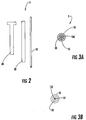
- Figure 2 illustrates an exploded view of one embodiment of the assembly 5.
- the inner member 10 can have a first length that is longer than the length of either the intermediate or outer member 20, 30.
- the intermediate member can have a length that is less than the inner member 10, but longer than the outer member 30.
- the intermediate member 20 is about 1-3 cm shorter than the inner member 10 and the cannula or outer member 30 can be about 1-4 cm shorter than the intermediate member 20.
- the overall length of the inner member 10 can be about 10 inches to about 13 inches.
- the members 10,20 and 30 can be provided as differently sized sets that allow for deep or shallow placement.
- the shallow probe placement can employ lengths that are 1/5-1/3 the length of the deep placement members.
- Figure 3A illustrates that the members 10,20,30 can be sized and configured to snugly abut each other. In other embodiments, the members 10,20,30 may have relatively small radial air gap spaces. Biocompatible anti-friction coatings may be used to facilitate in situ adjustment (extension and/or retraction of the inner member 10) during a procedure.
- Figure 3A also illustrates that the inner member core 10c can be solid.
- Figure 3B illustrates that the inner member core 10c can be open, allowing for additional interventional probes to be guided/inserted therethrough without removing the inner member 10.
- Figure 4 illustrates that in some embodiments, the assembly 5 can be configured to define a loopless MRI antenna 5I.
- the inner member 10 can include a core that is plated with a conductive material or coating for improved conductivity and an outer layer of a thin dielectric 11. The dielectric can terminate to expose the distal end or tip.
- the outer tubing layer 30 can define a shield.
- the intermediate member 20 can include a dielectric layer 23 that may be coated for improved conductivity.
- a distal section of the outer tube 30 can be coiled 30c to improve loading.
- the proximal portion of the body of the assembly 5 can connect to a micro BNC connector 52, as shown.
- Figure 1 illustrates that a coaxial cable 40 can electrically connect to the inner member 10 and the intermediate member 20.
- the inner member 10 can merge into a connector 50 at its proximal end portion.
- the coaxial cable 40 can connect to an MRI scanner interface 230 and the connector 50 can communicate with a recorder ( see, e.g., Figure 5 ).
- the inner member 10 can include at least one recording electrode 15 on a distal portion thereof.
- different regions in the brain provide different "signature signals" with intensities, frequencies and/or pitches (typically readings of between about 1-4 microvolts) which can be sensed or recorded and are identifiable.
- the conductive core 10c can connect to the electrode 15 and the insulating layer on the inner member 10 can be configured to expose the electrode 15 (i.e., the insulating layer or material can provide a gap or terminate at the location of the electrode).
- the electrode 15 can be generally cylindrical or configured in any desired configuration.
- the assembly 5 can define a bimodal device that provides both a microelectrode recording operational mode as well as an internal MRI antenna receive mode (typically electrically isolated so that each mode is not concurrently operative).
- the assembly 5 can be configured so that components of the cannula 75 and microelectrode 15 system form one or more internal MRI RF antennas 5I that can be matched and tuned at the MRI frequency of interest.
- the assembly 5 can include or be in communication with a matching/tuning and RF decoupling circuit 124 ( Figure 5 ) as well as a splitter circuit 125 ( Figure 5 ).
- the matching/tuning and RF decoupling circuit 124 is configured to decouple the probe during RF excitation so as to inhibit operation during active RF transmission (activating the antenna to receive MRI signals after RF excitation).
- the splitter circuit 125 can be configured to electrically isolate the probe or separate the operation of the MRI RF signal(s) from the microelectric recording (EPG) signal(s).
- the splitter circuit 125 can include either a high pass and/or a low pass filter. Additional components of the antennas can be implemented as RF chokes as described for example, in U.S. Patent No. 6,284,971 , the contents of which are hereby incorporated by reference as if recited in full herein.
- RF chokes refers to a shielding layer configuration that provides an electrical length of less than or equal to ⁇ /4 (from the perspective of external electromagnetic waves) to inhibit the formation and/or propagation of RF induced current or standing waves in an AC (alternating current, e.g., diathermy applications) or RF exposure environment.
- the physical length that provides the electrical wavelength may vary depending on the materials used in fabricating the probe (such as dielectric constant) and the magnetic field in which it is used.
- a typical system 5 may comprise two discrete members, a cannula 75 and an inner tubular member 10, that may be an insulated wire, that can be termed an MRI antenna probe 10.
- the cannula 75 can comprise two or more concentric tubes, each insulated from the other and arranged to form an MRI antenna 5I , namely a loopless/dipole antenna ( Figure 4 ). If two concentric tubes, insulated from each other, are used, the inner tube 10 forms the core of the loopless antenna and the outer tube forms the shield.
- the tubes can be arranged so that the innermost tube 10 forms the core, the intermediate 20 the shield/ground and the outermost 30 can be connected to the intermediate tubing at the proximal end to form an RF choke as shown in Figure 1 .
- An internal member 10 can cooperate with the cannula 75 and act as an MRI antenna 5I (an RF antenna), which is advanced in the cannula 75 and used to obtain an MRI image of the surrounding anatomy.
- a recording electrode 15 thereon can be used to obtain and/or measure microelectric signals from the intracranial tissue.
- the MRI image data and microrecording data can facilitate more exact identification of target cranial anatomy for placement of an implantable DBS lead systems.
- the shield 30c can be coiled in the distal section to reduce the overall loading length.
- the entire length of the inner member 10 may be insulated with a polymeric dielectric, except for the distal tip of the inner member 10 and, in some embodiments, the distal tip of the shielding 11. This is to allow measurement of the EPG or EEG signal from the cranial tissue. If the EPG measurement is not a desired feature, the entire length of the inner member 10 may be insulated to prevent contact with biological fluids.
- a micro-BNC connector 52 facilitates connecting to a matching/tuning and decoupling circuit and/or a RF-EPG signal splitter circuit, as shown in Figure 5 .
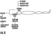
- the system 5 may be used with an MRI scanner as shown in Figure 6 .
- the inner member 10 (and as appropriate, the intermediate tubing 20) can be removed and a lead system or other interventional device can be introduced (and implanted as desired) using the cannula 75 as shown in Figure 7A .
- the lead system or other interventional device can be positioned with the inner member 10 in place where the inner member comprises a hollow core as shown in Figure 3B .
- the inner member 10 and the cannula 75 can be made to work in conjunction with each other, where the function of the cannula tubings can be dependent on the length of the member 10 in the cannula 75.
- the cannula 75 will be advanced in the cranial anatomy, and the imaging coil will be advanced in the cannula and into the tissue.
- the antenna probe member 10 When the antenna probe member 10 is partially outside the distal end of the cannula 75, the probe 10 acts as the core 10c of the loopless antenna 5I and the cannula 75 as the shield of the loopless antenna.
- the cannula 75 ceases to act as the shield but acts as an RF choke to the inner member 10. This mechanism can be built in into the handle section of the inner member 10.
- the cannula can be configured to define all or a portion of an inductor loop antenna configuration, a multiple inductor loop configuration, an opposed solenoid coil, etc.
- the inner imaging antenna probe may be configured in other manners, such as, but not limited to an inductor loop coil, a quadrature loop coil, etc.
- the RF splitter circuit 125 may be implemented in the ground circuitry, if the distal end of the coiled shield 30c is used to obtain or measure micro recording or EP signals.
- the concentric tubings 20, 30 of the cannula 75 system 5 are not permanently connected to each other and are able to slide inside the other as noted above.
- the components perform different electrical functions.
- the cannula 75 can include two concentric tubings, which slide relative to each other and can be removed as desired or appropriate during the procedure.
- the inner tubing 10 extends out of the intermediate tubing 20, it can act as the core of the loopless antenna.
- the inner member 10 can also include one or two or more concentric (which may be slidable) tubes, all insulated from each other, and with an innermost wire.
- the innermost wire forms the core of the loopless antenna
- the outer tubings can form the shield and/or the balun.
- the cannula related tubings can form a part of the shield or the RF choke balun, depending on the location of the inner coils with respect to the cannula tubings.
- the cannula 75 can be configured with a generally rigid body and/or a body that has increased rigidity relative to at least the inner member 10.
- the cannula 75 can be configured to slidably receive at least the distal and intermediate portions of the inner member 10 and/or probe body 100 ( Figure 7A ) to guide the inner member 10 into position.
- the cannula 75 and/or associated members 10,20,30 can be single-use and disposable and provided as a sterilized component in a medical kit, or it may be re-used as a standard component and sterilized by the user/clinic.
- the cannula 75 can be configured according to a desired body entry location; e.g., for oral entry, the cannula 75 can be formed into a bite block, nasal cavity or ear plug member, and for non-neural uses, such as placement in the spinal column, no cannula may be required.
- the cannula 75, the members 10, 20, 30, an MRI interface cable and connectors 40, 50 can comprise non-magnetic MRI compatible material(s).
- the kit can include an implantable pulse generator 50 as well as the implantable stimulation lead 100 which may also comprise MRI compatible materials to allow post-placement MRI interrogation of the subject.
- the stimulation lead 100 can be configured to be guided through the same cannula 75 as the antenna 5I.
- the antenna core 10 is removed after a desired location is determined, then the stimulation lead or other device is guided through the cannula 75 to the target location. In other embodiments, the core remains in position and the interventional device guided therethrough as noted above.
- the MRI antenna 51 is configured to pick-up MRI signals internally from local tissue during an MRI procedure.
- the antenna 51 has a focal length or signal-receiving length of between about 1-5 cm, and typically is configured to have a viewing length to receive MRI signals from local tissue of between about 1-2.5 cm.
- the MRI antenna 5I can be a loopless antenna such as shown in Figure 4 .
- other antenna configurations can be used, such as, for example, a whip antenna, a coil antenna, and/or a looped antenna. See, e.g., U.S. Patent Nos. 5,699,801 ; 5,928,145 ; 6,263,229 ; 6,606,513 ; 6,628,980 ; 6,284,971 ; 6,675,033 ; and 6,701,176 .
- the antenna may be used to guide placement of interventional probes and are not necessarily used to generate to guide placement of interventional probes and are not necessarily used to generate images of local structure.
- the electrode(s) of the antenna 5I and/or the stimulation lead 100 can be sized and configured to "fit" the desired internal target, which may be a relatively small region, such as less than about 1-3 mm.
- the electrode(s) 15 can be held on a distal portion of the probe body.
- the assembly has two primary operational modes with different electric transmission paths, which are electrically directed using the splitter circuit 125 ( Figure 5 ).
- an RF excitation pulse is transmitted to a subject.
- the MRI antenna is decoupled during RF transmission, then operative during a receive cycle to receive signal from local tissue.
- the recording electrode(s) 15 is typically isolated via the splitter circuit 125 so that only the MRI antenna is active.
- the MRI interface communicates with the MRI scanner.
- MRI guided clinical implantation of the probe can first be used as an MRI antenna 5I to provide high resolution imaging of the target internal anatomy (such as neural tissue) and to locate the position of the electrode 15 in the body by obtaining MRI signals and hence, images, that are acquired by the external coils and/or internal MRI antenna.
- the electrodes 15 can also be used to assess location via acquiring or sensing electrical signals from the target (neural) anatomy.
- FIGS 7A and 7B illustrate a dual probe system according to other embodiments of the present invention.
- an MRI antenna probe 120a and a stimulation probe 120b can be sized and configured to serially enter a common cannula 75.
- the antenna probe 120a and/or the stimulation probe 120b can each include at least one sensing electrode.
- Each probe 120a, 120b can have a graduated scale or coordinate system that allows the antenna probe 120a to be used to obtain MRI imaging data used to locate the target in vivo location.
- the cannula 75 can include MRI fiducial markers (not shown).
- the antenna probe 120a can then be removed and replaced with the stimulation probe 120b that can be automatically advanced in the same trajectory to the same position based on the data provided by the antenna probe 120a and the controlled insertion to the location defined by the antenna probe 120a, typically to a high degree of precision.
- the two probes 120a, 120b can be sized and configured to have substantially the same cross-sectional area.
- a non-conductive elastomeric sleeve (not shown), coating or other configuration can be used to size the probes 120a, 120b to snugly fit the cannula 75 as desired.
- an insert can be used to adjust the size of the cannula 75 to correspond to that of the probe in use (also not shown).
- Figure 7B illustrates that a kit 80 can comprise the two probes 120a, 120b and, optionally, the cannula 75.
- the antenna probe 120a can be configured to connect with the MRI interface while the stimulation probe 120b can be configured to connect to the implantable pulse generator, each of which (along with respective leads) may also form part of the medical kit 80.
- the cannula 75 may be sized and configured to be a universal delivery system cannula 75 that can slidably serially receive selectable different elongate probes, such as the microelectrode and stimulation electrode probes discussed above.
- the universal system cannula 75 can be configured to selectably receive different elongate members, such as, but not limited to, at least two of the following MRI compatible devices: an MRI antenna probe, an optic probe, a depth probe, an EEG probe, a stimulation probe (which may be implantable), a biopsy probe, an ablation probe, and a drug and/or fluid delivery and/or extraction probe (catheter, shunt and the like).
- the MRI antenna probe may be a standalone MRI antenna probe that cooperates with the cannula 75, or may be combined with any of the other probe functions.
- the probe 5 can be configured to provide a combination biopsy needle and MRI antenna probe when positioned in the cannula 75.
- An example of a needle antenna is described in U.S. Patent 6,606,513 , the contents of which are hereby incorporated by reference as if recited in full herein.
- the cannula 75 can have an ID (inner diameter) that allows different selected probes to be guided therethrough, or one or more of the tubes (such as the intermediate tube 20 in a three tube configuration) can be removed when the cannula 75 is used with larger probes. That is, one or more of the cannula tubes can act a removable sleeve for certain probes.
- the cannula 75 has a fixed ID, and the different probes have a substantially similar OD (outer diameter), or one or more of the different probes can use sleeves to provide the desired size that allow them to be guided reliably into location with the same cannula 75.
- the OD of the different selectable inner members, usable with a universal cannula 75 can be between about 0.5-3 mm, and in some embodiments is about 1.5 mm or less, typically about 1.3 mm or less, and more typically between about 1.27-1.3 mm.
- the OD of the cannula 75 may be about 2 mm.
- the members 10, 20 and 30 can be provided as differently sized sets that allow for deep or shallow placement.
- the shallow probe placement can employ lengths that are 1/5-1/3 the length of the deep placement members described above.
- the cannula 75 and probe members can be provided as differently sized sets that allow for deep or shallow in vivo placement and/or for use with about a 1.5T or about a 3.0T MRI System.
- the shallow probe placement can employ lengths that are at least about 3 cm, typically about 3 cm.
- the deep placement members can be at least about 7 cm long, typically between about 7-8 cm long. Different French size probes and/or different length probes may generate different loads and tuning may be adjusted accordingly.
- the antenna probes can be tuned remotely so that substantially the entire length or a selected portion thereof is active.
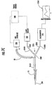
- the inner member 10 (or one of the selectable inner member probes) can be configured as an NIR (near infrared imaging) optic probe 220. See Giller et al., Validation of a near-infrared probe for detection of thin intracranial white matter structures, J. Neurosurg 98: 1299-1306 (2003 ) and U.S. Patent 6,567,690 , the contents of which are hereby incorporated by reference as if recited in full herein.
- the inner member 10 can be configured as a combination NIR optic probe and to provide an MRI antenna as shown in Figure 7C .
- the probe 220 can comprise an elongate fiberoptic fiber or fiber bundle 220f that can be cladded (meaning the fiber optic(s) encased) with a desired MRI compatible conductive material, such as gold.
- the cladding or casing layer may terminate before the distal end of the member 220 (exposing the outer surface(s) of the optic fiber). Placing the cladded fiber optic package in the cannula 75 allows the combination probe 220 to cooperate with the cannula 75 and/or define independently, both an MRI antenna and an NIR imaging device.
- the probe 220 can be in communication with a light source 222 (typically a broad band light source) and a spectrometer 225 (typically a CCD array spectrometer) via the fiber(s) 220f .
- the spectrometer can provide tissue data 225d such as wavelength versus photon output based on local tissue characteristics ( i.e., such as reflectance or other desired optical property).
- the light source 222 and/or the spectrometer 225 can be placed in or out of the MRI suite to avoid MRI interference and/or can be configured with MRI compatible components and materials.
- the system can also include an MRI interface 230 electrically connected to the probe 220 via (coaxial) cable 221.
- the fiber(s) 220f can comprise a splitter 220s at a proximal end portion to provide separate light input and output paths 220i, 220e.
- the coaxial cable 40 can be in electrical communication with the cladding of the probe 220 as well as the intermediate cannula member 20, as described for the embodiment shown in Figure 1 .
- the MRI antenna or probe can be in communication with an RF decoupler circuit 124 ( Figure 5 ).
- An optional light and MRI timer 240 can be used to facilitate concurrent signal acquisition (registration) of a common region.
- the NIR probe function allows forward views (typically about 1-1.5 mm in front of the probe tip) while the MRI antenna can gather signal data of tissue proximate a distal end portion of the probe.
- FIG. 9 is a block diagram of exemplary embodiments of data processing systems that illustrates systems, methods, and computer program products in accordance with embodiments of the present invention.
- the data processing systems may be incorporated in a digital signal processor in either the implantable pulse generator and/or MRI scanner interface and/or be in communication therewith.
- the processor 410 communicates with the memory 414 via an address/data bus 448.
- the processor 410 can be any commercially available or custom microprocessor.
- the memory 414 is representative of the overall hierarchy of memory devices containing the software and data used to implement the functionality of the data processing system.
- the memory 414 can include, but is not limited to, the following types of devices: cache, ROM, PROM, EPROM, EEPROM, flash memory, SRAM, and DRAM.
- the memory 414 may include several categories of software and data used in the data processing system: the operating system 452; the application programs 454; the input/output (I/O) device drivers 458; the MRI Antenna operation or Electrode Operation Module 450; and data 456.
- the operating system 452 the application programs 454
- the input/output (I/O) device drivers 458 the input/output (I/O) device drivers 458
- the MRI Antenna operation or Electrode Operation Module 450 and data 456.
- the operating system 452 may be any operating system suitable for use with a data processing system, such as OS/2, AIX, DOS, OS/390 or System390 from International Business Machines Corporation, Armonk, NY, Windows CE, Windows NT, Windows95, Windows98, Windows2000 or other Windows versions from Microsoft Corporation, Redmond, WA, Unix or Linux or FreeBSD, Palm OS from Palm, Inc., Mac OS from Apple Computer, LabView, or proprietary operating systems.
- the I/O device drivers 458 typically include software routines accessed through the operating system 452 by the application programs 454 to communicate with devices such as I/O data port(s), data storage 456 and certain memory 414 components.
- the application programs 454 are illustrative of the programs that implement the various features of the data processing system and can include at least one application, which supports operations according to embodiments of the present invention.
- the data 456 represents the static and dynamic data used by the application programs 454, the operating system 452, the I/O device drivers 458, and other software programs that may reside in the memory 414.
- Module 450 is illustrated, for example, with reference to the Module 450 being an application program in Figure 9 , as will be appreciated by those of skill in the art, other configurations may also be utilized while still benefiting from the teachings of the present invention.
- the Module 450 may also be incorporated into the operating system 452, the I/O device drivers 458 or other such logical division of the data processing system.
- the present invention should not be construed as limited to the configuration of Figure 9 which is intended to encompass any configuration capable of carrying out the operations described herein.
- the Module 450 can communicate with other components, such as an MRI scanner.
- the I/O data port can be used to transfer information between the data processing system or another computer system or a network (e.g ., the Internet) or to other devices controlled by the processor.
- These components may be conventional components such as those used in many conventional data processing systems, which may be configured in accordance with the present invention to operate as described herein.
- the computer-readable program code can include computer readable program code that controllably engages a first or second operational mode for a MRI compatible antenna and recording probe with at least one electrode and an MRI antenna.
- the first operational mode having a first transmission path connecting the MRI antenna with an MRI scanner and decoupling the electrode during MRI operation and the second operational mode having a second transmission path connecting the electrode with a recording source during electrical recording.
- the computer readable program code may be configured to time the selection of the operational mode to occur proximate in time but after an MRI signal acquisition in the first operational mode.
- the computer readable program code may be configured to operate the second mode to obtain microrecordings of local tissue in substantially real time proximate in time to an MRI signal acquisition by the MRI antenna in the first operational mode.
- the computer readable program code may be configured to obtain a plurality of MRI signals of local neural tissue proximate the MRI antenna in substantially real time, then obtain a plurality of microrecordings of the local neural tissue to allow a clinician to track placement of the probe using both MRI data and audio data.
- each block in the flow charts or block diagrams represents a module, segment, or portion of code, which comprises one or more executable instructions for implementing the specified logical function(s).
- the functions noted in the blocks may occur out of the order noted in the figures. For example, two blocks shown in succession may in fact be executed substantially concurrently or the blocks may sometimes be executed in the reverse order, depending upon the functionality involved.
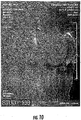
- Figures 8A-8D illustrate a prototype configuration of a cannula 75 with MRI antenna 5I formed by the inner member 10 and cannula 75 that was used to obtain the image of the primate shown in Figure 10 .
- the MRI compatible cannula and microelectrode configuration was used in vivo with a Siemens Allegra® 2.9T scanner.
- a 2 mm outer diameter cannula included three concentric insulated tubes from Nitinol configured to define a loopless RF antenna.
- the innermost tube (1.5 mm inner diameter) formed the core of the loopless antenna and provided a conduit to advance an additional MRI-antenna/microelectrode component.
- the intermediate tube formed the shield of the antenna with the outermost tube connected to the intermediate tubeat a proximal end to form a RF choke.
- the inner diameter of the cannula and the outer surfaces were coated with a thin polyurethane insulation and the entire cannula part of the assembly was insulated by a 0.001 inch polyimide tube.
- the micro-electrode loopless antenna member was fabricated from Nitinol tube with an insulated gold-plated wire inside the Nitinol tube forming the core of the antenna.
- the dipole end portion of the antenna was about 1.5 cm and was not insulated at the outermost end portion for about 1 mm to permit EEG measurements.
- the shield of the antenna was coiled at the distal end portion to reduce the overall loading length to about 3 cm.
- the member was insulated by a 500 micron polyester layer (except for the distal tip of the member to permit EEG measurements as noted above).
- the cannula and microelectrode antenna member were matched and tuned to about 123.2MHz and decoupled from pick-up during MRI excitation via a decoupling circuit/switch similar to that described in Ocali et al., Intravascular magnetic resonance imaging using a loopless catheter antenna, Magn Reson Med, 1997; 37:pp.112-118 .
- MRI testing of the cannula and antenna/microelectrode member were performed on the 2.9T Siemen's Allegra® scanner.
- RF power deposition safety testing was carried out in a polyacrylamide gel phantom of conductivity 0.9 S/m.
- a nominal 4W/kg SAR (head) MRI sequence was applied for 3.4 minutes.
- the cannula and the microelectrode/antenna member were placed about 1 cm from the edge of the phantom and the local temperature was measured directly using FISO fiber-optic temperature probes. Actual SAR was calculated from the rate of the initial temperature rise and the specific heat of the gel.
- the MRI signal to noise ratio (SNR) of the microlectrode/antenna and cannula system was tested in a saline phantom with variable depths of insertion (3 cm and 10 cm) to simulate some clinical conditions.
- SNR signal to noise ratio
- the cannula/loopless antenna and coaxial cable had an impedance of about 25 ohms.
- the RF choke created between the primary and secondary shielding had an isolation of about 550 ohms when the antenna/cannula was loaded up to about 4 cm in the saline phantom.
- the coaxial cable of the microelectrode/antenna member had an impedance of about 32 ohms.
- the SNR profile of the antenna demonstrated about a 50% improvement over the external head coil in a circular region of about 5 mm radius around the distal end portion of the antenna/microelectrode member.
- the signal from the scanner's had coil depicts the overall cranial anatomy while the local SNR enhancement provided by the cooperating MRI compatible cannula and microelectrode/antenna member as the coil advanced into the STN is shown in Figure 10 .
- the local SNR improvement can provide enhanced local spatial registration for precise anatomical guidance/positioning
Landscapes
- Health & Medical Sciences (AREA)
- Life Sciences & Earth Sciences (AREA)
- Physics & Mathematics (AREA)
- General Health & Medical Sciences (AREA)
- Pathology (AREA)
- Engineering & Computer Science (AREA)
- Molecular Biology (AREA)
- Surgery (AREA)
- Nuclear Medicine, Radiotherapy & Molecular Imaging (AREA)
- Biomedical Technology (AREA)
- Heart & Thoracic Surgery (AREA)
- Medical Informatics (AREA)
- Veterinary Medicine (AREA)
- Biophysics (AREA)
- Animal Behavior & Ethology (AREA)
- Public Health (AREA)
- High Energy & Nuclear Physics (AREA)
- Radiology & Medical Imaging (AREA)
- Human Computer Interaction (AREA)
- Condensed Matter Physics & Semiconductors (AREA)
- General Physics & Mathematics (AREA)
- Magnetic Resonance Imaging Apparatus (AREA)
Claims (9)
- Medizinisches In-vivo-Tiefenhirn-Sondensystem, mit:einer MRT-kompatiblen Kanüle (75), die mehrere im Allgemeinen konzentrische, sich axial erstreckende Röhren (20, 30) mit einer Aufnahmebohrung aufweist; undein längliches Antennenelement (10) mit einem Kern, der einen Leiter und eine Isolationsschicht aufweist, und der konfiguriert ist, verschiebbar durch die Kanülenbohrung vorzudringen, um elektrisch mit der Kanüle zusammenzuarbeiten, um eine schleifenlose MRT-Empfangsantenne zu definieren;wobei eine der mehreren im Allgemeinen konzentrischen, sich axial erstreckenden Röhren (20, 30) eine Abschirmung der schleifenlosen MRT-Empfangsantenne bildet und vom Kern durch die Isolationsschicht isoliert ist;
dadurch gekennzeichnet, dass
das längliche Antennenelement (10) eine Aufzeichnungselektrode (15) aufweist, die an einem distalen Abschnitt des länglichen Antennenelements (10) angeordnet ist, wobei die Isolationsschicht am Ort der Aufzeichnungselektrode (15) einen Spalt bereitstellt oder dort endet, um die Aufzeichnungselektrode (15) freizulegen. - Sondensystem nach Anspruch 1, wobei die Aufzeichnungselektrode ein zylindrisches Band ist.
- Sondensystem nach Anspruch 2, wobei das Sondensystem mindestens zwei Betriebsarten aufweist, die eine erste MRT-Signalbetriebsart, wobei das Antennenelement MRT-Signale von einem lokalen Gewebe empfängt, und eine zweite Signalaufzeichnungsbetriebsart umfassen, wobei die Aufzeichnungselektrode elektrische Signale von einem lokalen Zielgewebe erhält.
- Sondensystem nach Anspruch 3, das ferner eine HF-Entkopplungsschaltung, die konfiguriert ist, die MRT-Empfangsantenne während einer MRT-Anregungs-HF-Übertragung zu isolieren, und eine Aufzeichnungssplitterschaltung aufweist, um die MRT-Empfangsantenne während der Aufzeichnungsbetriebsart zu entkoppeln.
- Sondensystem nach Anspruch 1, das ferner ein MRT-kompatibles interventionelles Sondenelement aufweist, das konfiguriert ist, sich verschiebbar durch die MRTkompatible Kanüle zu erstrecken.
- Sondensystem nach Anspruch 1, wobei die Kanüle ein Zwischenröhrenelement und ein Außenelement aufweist, das im Allgemeinen mindestens eine größere Länge des Zwischenelements umhüllt.
- Sondensystem nach Anspruch 6, wobei das Antennenelement eine erste Länge aufweist, das Zwischenelement eine zweite Länge aufweist und das Außenelement eine dritte Länge aufweist, wobei die erste Länge länger als die zweite und dritte Länge ist und die zweite Länge länger als die dritte Länge ist.
- Sondensystem nach Anspruch 1, das ferner eine implantierbare Stimulationsleitung aufweist, die bemessen und konfiguriert ist, sich verschiebbar durch die Bohrung der Kanüle zu erstrecken, nachdem das Antennenelement daraus entfernt ist.
- Sondensystem nach Anspruch 1, wobei das Antennenelement einen hohlen Kern aufweist und konfiguriert ist, dort hindurch verschiebbar ausgewählte interventionelle Vorrichtungen aufzunehmen.
Applications Claiming Priority (3)
| Application Number | Priority Date | Filing Date | Title |
|---|---|---|---|
| US59140904P | 2004-07-27 | 2004-07-27 | |
| US60823204P | 2004-09-09 | 2004-09-09 | |
| PCT/US2005/026508 WO2006014966A2 (en) | 2004-07-27 | 2005-07-26 | Mri systems having mri compatible universal delivery cannulas with cooperating mri antenna probes and related systems and methods |
Publications (3)
| Publication Number | Publication Date |
|---|---|
| EP1786320A2 EP1786320A2 (de) | 2007-05-23 |
| EP1786320A4 EP1786320A4 (de) | 2009-06-03 |
| EP1786320B1 true EP1786320B1 (de) | 2016-09-14 |
Family
ID=35787774
Family Applications (1)
| Application Number | Title | Priority Date | Filing Date |
|---|---|---|---|
| EP05775680.1A Active EP1786320B1 (de) | 2004-07-27 | 2005-07-26 | Mri-systeme mit mri-kompatiblen universellen ablieferungskanülen mit kooperierenden mri-antennensonden und diesbezügliche systeme und verfahren |
Country Status (6)
| Country | Link |
|---|---|
| US (1) | US8108028B2 (de) |
| EP (1) | EP1786320B1 (de) |
| JP (1) | JP5288797B2 (de) |
| CN (1) | CN101031237B (de) |
| CA (1) | CA2575313C (de) |
| WO (1) | WO2006014966A2 (de) |
Families Citing this family (47)
| Publication number | Priority date | Publication date | Assignee | Title |
|---|---|---|---|---|
| US8256430B2 (en) | 2001-06-15 | 2012-09-04 | Monteris Medical, Inc. | Hyperthermia treatment and probe therefor |
| WO2006031317A2 (en) * | 2004-08-09 | 2006-03-23 | The Johns Hopkins University | Implantable mri compatible stimulation leads and antennas and related systems and methods |
| AU2006320611A1 (en) | 2005-11-29 | 2007-06-07 | Surgi-Vision, Inc. | MRI-guided localization and/or lead placement systems, related methods, devices and computer program products |
| US8529514B2 (en) * | 2006-05-05 | 2013-09-10 | Children's Hospital Medical Center | Cannula with removable sleeve |
| US8175677B2 (en) * | 2007-06-07 | 2012-05-08 | MRI Interventions, Inc. | MRI-guided medical interventional systems and methods |
| US8315689B2 (en) | 2007-09-24 | 2012-11-20 | MRI Interventions, Inc. | MRI surgical systems for real-time visualizations using MRI image data and predefined data of surgical tools |
| CA2700523A1 (en) | 2007-09-24 | 2009-04-02 | Surgivision, Inc. | Mri-guided medical interventional systems and methods |
| EP2213318A4 (de) * | 2007-10-31 | 2011-03-09 | Olympus Corp | System zur verabreichung einer arzneimittellösung und kanüle zur verabreichung der arzneimittellösung |
| US8320647B2 (en) | 2007-11-20 | 2012-11-27 | Olea Medical | Method and system for processing multiple series of biological images obtained from a patient |
| WO2009088936A1 (en) * | 2008-01-03 | 2009-07-16 | The Government Of The United States Of America, As Represented By The Secretary, Department Of Health And Human Services | Mri guidewire |
| WO2010030373A2 (en) * | 2008-09-12 | 2010-03-18 | Surgivision, Inc. | Intrabody mri stacked flat loop antennas and related systems |
| US8364279B2 (en) | 2008-09-25 | 2013-01-29 | Boston Scientific Neuromodulation Corporation | Electrical stimulation leads having RF compatibility and methods of use and manufacture |
| US8478424B2 (en) * | 2009-02-23 | 2013-07-02 | Medtronic, Inc. | Medical lead having coaxial connector |
| WO2011025836A1 (en) * | 2009-08-25 | 2011-03-03 | The Regents Of The University Of California | Optimized placement of cannula for delivery of therapeutics to the brain |
| EP2338560B1 (de) * | 2009-12-22 | 2015-11-04 | Biotronik CRM Patent AG | Implantierbarer Kardioverter-Defibrillator (ICD) mit MRT-Störerkennungseinheit |
| EP2380489A1 (de) * | 2010-04-26 | 2011-10-26 | Biotronik CRM Patent AG | Ableitvorrichtung und MRI-sicheres Kathetersystem |
| US10517667B2 (en) | 2014-05-16 | 2019-12-31 | Biosense Webster (Israel) Ltd. | Catheter tip with microelectrodes |
| CN102280688A (zh) * | 2011-04-29 | 2011-12-14 | 北京大学 | 一种磁共振管腔天线装置 |
| CN104602638B (zh) | 2012-06-27 | 2017-12-19 | 曼特瑞斯医药有限责任公司 | 用于影响对组织进行治疗的系统 |
| US9498290B2 (en) | 2012-07-19 | 2016-11-22 | MRI Interventions, Inc. | Surgical navigation devices and methods |
| US10206693B2 (en) * | 2012-07-19 | 2019-02-19 | MRI Interventions, Inc. | MRI-guided medical interventional systems and methods |
| US9192446B2 (en) | 2012-09-05 | 2015-11-24 | MRI Interventions, Inc. | Trajectory guide frame for MRI-guided surgeries |
| US8912976B2 (en) * | 2012-09-12 | 2014-12-16 | Varian Semiconductor Equipment Associates, Inc. | Internal RF antenna with dielectric insulation |
| CN104871024A (zh) * | 2012-12-18 | 2015-08-26 | 皇家飞利浦有限公司 | 用于表面和身体温度测量的可重复使用的mr 安全温度探头 |
| US9412076B2 (en) * | 2013-07-02 | 2016-08-09 | Surgical Information Sciences, Inc. | Methods and systems for a high-resolution brain image pipeline and database program |
| US10675113B2 (en) | 2014-03-18 | 2020-06-09 | Monteris Medical Corporation | Automated therapy of a three-dimensional tissue region |
| US9504484B2 (en) | 2014-03-18 | 2016-11-29 | Monteris Medical Corporation | Image-guided therapy of a tissue |
| US9486170B2 (en) | 2014-03-18 | 2016-11-08 | Monteris Medical Corporation | Image-guided therapy of a tissue |
| US9782581B2 (en) | 2014-06-27 | 2017-10-10 | Boston Scientific Neuromodulation Corporation | Methods and systems for electrical stimulation including a shielded sheath |
| CN104965002B (zh) * | 2014-12-16 | 2018-04-17 | 湖南省茶叶研究所(湖南省茶叶检测中心) | 降低触角电位仪背景噪音的装置及使用该装置检测触角的方法 |
| WO2016160423A1 (en) | 2015-03-27 | 2016-10-06 | Boston Scientific Neuromodulation Corporation | Systems and methods for making and using electrical stimulation systems to reduce rf-induced tissue heating |
| US10327830B2 (en) | 2015-04-01 | 2019-06-25 | Monteris Medical Corporation | Cryotherapy, thermal therapy, temperature modulation therapy, and probe apparatus therefor |
| JP6771019B2 (ja) * | 2015-04-07 | 2020-10-21 | アルファ オメガ ニューロ テクノロジーズ リミテッド | ラーセン効果低減電極 |
| US10173055B2 (en) | 2015-04-30 | 2019-01-08 | Boston Scientific Neuromodulation Corporaation | Electrical stimulation leads and systems having a RF shield along at least the lead and methods of making and using |
| US10751123B2 (en) * | 2015-10-30 | 2020-08-25 | Washington University | Thermoablation probe |
| USD824027S1 (en) | 2016-01-13 | 2018-07-24 | MRI Interventions, Inc. | Fins for a support column for a surgical trajectory frame |
| USD829904S1 (en) | 2016-01-13 | 2018-10-02 | MRI Interventions, Inc. | Curved bracket for surgical navigation systems |
| US10376333B2 (en) | 2016-01-14 | 2019-08-13 | MRI Interventions, Inc. | Devices for surgical navigation systems |
| JP2019531787A (ja) | 2016-08-30 | 2019-11-07 | ザ リージェンツ オブ ザ ユニバーシティ オブ カリフォルニア | 生物医学的ターゲティング及びデリバリーの方法並びにそれを実行するための装置及びシステム |
| US10905497B2 (en) | 2017-04-21 | 2021-02-02 | Clearpoint Neuro, Inc. | Surgical navigation systems |
| EP3654860A1 (de) | 2017-07-17 | 2020-05-27 | Voyager Therapeutics, Inc. | Trajektoriearrayführungssystem |
| US10826179B2 (en) | 2018-03-19 | 2020-11-03 | Laurice J. West | Short dual-driven groundless antennas |
| US20190374666A1 (en) * | 2018-06-07 | 2019-12-12 | Dickey Arndt | Systems and method for decontaminating a tube |
| EP3949007A1 (de) * | 2019-03-29 | 2022-02-09 | Saint-Gobain Glass France | Antennenscheibe |
| US11172984B2 (en) | 2019-05-03 | 2021-11-16 | Biosense Webster (Israel) Ltd. | Device, system and method to ablate cardiac tissue |
| WO2021007815A1 (zh) * | 2019-07-17 | 2021-01-21 | 诺尔医疗(深圳)有限公司 | 一种抗弯折的颅内电极制作方法、颅内深部电极以及脑电图仪 |
| EP4138709A4 (de) * | 2020-04-22 | 2024-05-15 | Transmural Systems LLC | Mrt-kompatible vorrichtungen |
Family Cites Families (53)
| Publication number | Priority date | Publication date | Assignee | Title |
|---|---|---|---|---|
| JPH01238873A (ja) * | 1988-03-15 | 1989-09-25 | W Bramer Paul | カテーテル |
| DE3831809A1 (de) * | 1988-09-19 | 1990-03-22 | Funke Hermann | Zur mindestens teilweisen implantation im lebenden koerper bestimmtes geraet |
| JPH02261428A (ja) * | 1989-03-31 | 1990-10-24 | Yokogawa Medical Syst Ltd | Mri用表面コイルのデカップリング回路 |
| US5928145A (en) * | 1996-04-25 | 1999-07-27 | The Johns Hopkins University | Method of magnetic resonance imaging and spectroscopic analysis and associated apparatus employing a loopless antenna |
| US5716377A (en) * | 1996-04-25 | 1998-02-10 | Medtronic, Inc. | Method of treating movement disorders by brain stimulation |
| US5735814A (en) * | 1996-04-30 | 1998-04-07 | Medtronic, Inc. | Techniques of treating neurodegenerative disorders by brain infusion |
| US5713923A (en) * | 1996-05-13 | 1998-02-03 | Medtronic, Inc. | Techniques for treating epilepsy by brain stimulation and drug infusion |
| US6176837B1 (en) * | 1998-04-17 | 2001-01-23 | Massachusetts Institute Of Technology | Motion tracking system |
| US6064899A (en) * | 1998-04-23 | 2000-05-16 | Nellcor Puritan Bennett Incorporated | Fiber optic oximeter connector with element indicating wavelength shift |
| US6319241B1 (en) * | 1998-04-30 | 2001-11-20 | Medtronic, Inc. | Techniques for positioning therapy delivery elements within a spinal cord or a brain |
| US8244370B2 (en) * | 2001-04-13 | 2012-08-14 | Greatbatch Ltd. | Band stop filter employing a capacitor and an inductor tank circuit to enhance MRI compatibility of active medical devices |
| US6701176B1 (en) * | 1998-11-04 | 2004-03-02 | Johns Hopkins University School Of Medicine | Magnetic-resonance-guided imaging, electrophysiology, and ablation |
| US9061139B2 (en) * | 1998-11-04 | 2015-06-23 | Greatbatch Ltd. | Implantable lead with a band stop filter having a capacitor in parallel with an inductor embedded in a dielectric body |
| US7844319B2 (en) * | 1998-11-04 | 2010-11-30 | Susil Robert C | Systems and methods for magnetic-resonance-guided interventional procedures |
| JP2003524452A (ja) | 1998-12-23 | 2003-08-19 | ヌバシブ, インコーポレイテッド | 神経監視カニューレシステム |
| US6708064B2 (en) * | 2000-02-24 | 2004-03-16 | Ali R. Rezai | Modulation of the brain to affect psychiatric disorders |
| EP1269206A2 (de) * | 2000-03-24 | 2003-01-02 | Surgi-Vision | Endoluminale sonde für die bildgebende magnetische resonanz |
| US8000801B2 (en) * | 2001-04-13 | 2011-08-16 | Greatbatch Ltd. | System for terminating abandoned implanted leads to minimize heating in high power electromagnetic field environments |
| US7853325B2 (en) * | 2001-04-13 | 2010-12-14 | Greatbatch Ltd. | Cylindrical bandstop filters for medical lead systems |
| US8977355B2 (en) * | 2001-04-13 | 2015-03-10 | Greatbatch Ltd. | EMI filter employing a capacitor and an inductor tank circuit having optimum component values |
| US8219208B2 (en) * | 2001-04-13 | 2012-07-10 | Greatbatch Ltd. | Frequency selective passive component networks for active implantable medical devices utilizing an energy dissipating surface |
| US7899551B2 (en) * | 2001-04-13 | 2011-03-01 | Greatbatch Ltd. | Medical lead system utilizing electromagnetic bandstop filters |
| US8989870B2 (en) * | 2001-04-13 | 2015-03-24 | Greatbatch Ltd. | Tuned energy balanced system for minimizing heating and/or to provide EMI protection of implanted leads in a high power electromagnetic field environment |
| US8437865B2 (en) * | 2001-04-13 | 2013-05-07 | Greatbatch Ltd. | Shielded network for an active medical device implantable lead |
| US8509913B2 (en) * | 2001-04-13 | 2013-08-13 | Greatbatch Ltd. | Switched diverter circuits for minimizing heating of an implanted lead and/or providing EMI protection in a high power electromagnetic field environment |
| US20070088416A1 (en) * | 2001-04-13 | 2007-04-19 | Surgi-Vision, Inc. | Mri compatible medical leads |
| US8600519B2 (en) * | 2001-04-13 | 2013-12-03 | Greatbatch Ltd. | Transient voltage/current protection system for electronic circuits associated with implanted leads |
| US8457760B2 (en) * | 2001-04-13 | 2013-06-04 | Greatbatch Ltd. | Switched diverter circuits for minimizing heating of an implanted lead and/or providing EMI protection in a high power electromagnetic field environment |
| US8849403B2 (en) * | 2001-04-13 | 2014-09-30 | Greatbatch Ltd. | Active implantable medical system having EMI shielded lead |
| US7787958B2 (en) * | 2001-04-13 | 2010-08-31 | Greatbatch Ltd. | RFID detection and identification system for implantable medical lead systems |
| US7916013B2 (en) * | 2005-03-21 | 2011-03-29 | Greatbatch Ltd. | RFID detection and identification system for implantable medical devices |
| CA2482202C (en) * | 2001-04-13 | 2012-07-03 | Surgi-Vision, Inc. | Systems and methods for magnetic-resonance-guided interventional procedures |
| GB2378760A (en) * | 2001-04-20 | 2003-02-19 | Marconi Medical Systems Uk Ltd | Surgical Probe |
| US6606521B2 (en) * | 2001-07-09 | 2003-08-12 | Neuropace, Inc. | Implantable medical lead |
| US20050014995A1 (en) * | 2001-11-09 | 2005-01-20 | David Amundson | Direct, real-time imaging guidance of cardiac catheterization |
| US7917219B2 (en) * | 2002-02-28 | 2011-03-29 | Greatbatch Ltd. | Passive electronic network components designed for direct body fluid exposure |
| US6985347B2 (en) * | 2002-02-28 | 2006-01-10 | Greatbatch-Sierra, Inc. | EMI filter capacitors designed for direct body fluid exposure |
| US8660645B2 (en) * | 2002-02-28 | 2014-02-25 | Greatbatch Ltd. | Electronic network components utilizing biocompatible conductive adhesives for direct body fluid exposure |
| CA2446476A1 (en) * | 2002-02-28 | 2003-09-04 | Greatbatch-Sierra, Inc. | Emi feedthrough filter terminal assembly utilizing hermetic seal for electrical attachment between lead wires and capacitor |
| JP2006512104A (ja) * | 2002-05-29 | 2006-04-13 | サージ−ビジョン インク | 磁気共鳴プローブ |
| US6987660B2 (en) * | 2003-02-27 | 2006-01-17 | Greatbatch-Sierra, Inc. | Spring contact system for EMI filtered hermetic seals for active implantable medical devices |
| US7038900B2 (en) | 2003-02-27 | 2006-05-02 | Greatbatch-Sierra, Inc. | EMI filter terminal assembly with wire bond pads for human implant applications |
| US7623335B2 (en) * | 2003-02-27 | 2009-11-24 | Greatbatch-Sierra, Inc | Hermetic feedthrough terminal assembly with wire bond pads for human implant applications |
| US6999818B2 (en) * | 2003-05-23 | 2006-02-14 | Greatbatch-Sierra, Inc. | Inductor capacitor EMI filter for human implant applications |
| US7039950B2 (en) | 2003-04-21 | 2006-05-02 | Ipolicy Networks, Inc. | System and method for network quality of service protection on security breach detection |
| US7765005B2 (en) * | 2004-02-12 | 2010-07-27 | Greatbatch Ltd. | Apparatus and process for reducing the susceptability of active implantable medical devices to medical procedures such as magnetic resonance imaging |
| US7489495B2 (en) * | 2004-04-15 | 2009-02-10 | Greatbatch-Sierra, Inc. | Apparatus and process for reducing the susceptibility of active implantable medical devices to medical procedures such as magnetic resonance imaging |
| US7035077B2 (en) * | 2004-05-10 | 2006-04-25 | Greatbatch-Sierra, Inc. | Device to protect an active implantable medical device feedthrough capacitor from stray laser weld strikes, and related manufacturing process |
| US7136273B2 (en) * | 2005-03-30 | 2006-11-14 | Greatbatch-Sierra, Inc. | Hybrid spring contact system for EMI filtered hermetic seals for active implantable medical devices |
| US7986143B2 (en) * | 2007-11-09 | 2011-07-26 | Vista Clara Inc. | Multicoil low-field nuclear magnetic resonance detection and imaging apparatus and method |
| EP2291219B1 (de) * | 2008-06-23 | 2017-10-25 | Greatbatch Ltd. | Frequenzselektive netzwerke mit passiven komponenten für implantierbare leitungen von implantierbaren medizinischen geräten mit einer energieableitenden oberfläche |
| WO2010030373A2 (en) * | 2008-09-12 | 2010-03-18 | Surgivision, Inc. | Intrabody mri stacked flat loop antennas and related systems |
| US8686725B2 (en) * | 2009-06-29 | 2014-04-01 | General Electric Company | System and apparatus for frequency translation of magnetic resonance (MR) signals |
-
2005
- 2005-07-26 CN CN2005800324512A patent/CN101031237B/zh active Active
- 2005-07-26 CA CA2575313A patent/CA2575313C/en active Active
- 2005-07-26 WO PCT/US2005/026508 patent/WO2006014966A2/en active Application Filing
- 2005-07-26 JP JP2007523732A patent/JP5288797B2/ja active Active
- 2005-07-26 EP EP05775680.1A patent/EP1786320B1/de active Active
- 2005-07-26 US US11/572,629 patent/US8108028B2/en active Active
Also Published As
| Publication number | Publication date |
|---|---|
| CN101031237A (zh) | 2007-09-05 |
| EP1786320A2 (de) | 2007-05-23 |
| EP1786320A4 (de) | 2009-06-03 |
| CN101031237B (zh) | 2012-11-14 |
| CA2575313C (en) | 2013-07-23 |
| US8108028B2 (en) | 2012-01-31 |
| WO2006014966A3 (en) | 2007-03-01 |
| JP5288797B2 (ja) | 2013-09-11 |
| CA2575313A1 (en) | 2006-02-09 |
| WO2006014966A2 (en) | 2006-02-09 |
| US20080097193A1 (en) | 2008-04-24 |
| JP2008508043A (ja) | 2008-03-21 |
Similar Documents
| Publication | Publication Date | Title |
|---|---|---|
| EP1786320B1 (de) | Mri-systeme mit mri-kompatiblen universellen ablieferungskanülen mit kooperierenden mri-antennensonden und diesbezügliche systeme und verfahren | |
| US11872086B2 (en) | Surgical image-guided navigation devices and related systems | |
| US8509876B2 (en) | Implantable MRI compatible stimulation leads and antennas and related systems and methods | |
| US8320990B2 (en) | Intrabody MRI stacked flat loop antennas and related systems | |
| US6904307B2 (en) | Magnetic resonance probes | |
| JP2008508984A5 (de) | ||
| US20140034377A1 (en) | Thin-sleeve apparatus for reducing rf coupling of devices in mri environments | |
| JP2013523236A (ja) | 神経組織と相互作用するためのデバイス、ならびにそれを作製および使用する方法 | |
| US20120182014A1 (en) | Magnetic resonance microcoil and method of use | |
| US9078588B2 (en) | MRI compatible intrabody stylets and related methods and systems | |
| Karmarkar et al. | An active microelectrode system for experimental MRI-guided intracranial intervention |
Legal Events
| Date | Code | Title | Description |
|---|---|---|---|
| PUAI | Public reference made under article 153(3) epc to a published international application that has entered the european phase |
Free format text: ORIGINAL CODE: 0009012 |
|
| 17P | Request for examination filed |
Effective date: 20070226 |
|
| AK | Designated contracting states |
Kind code of ref document: A2 Designated state(s): AT BE BG CH CY CZ DE DK EE ES FI FR GB GR HU IE IS IT LI LT LU LV MC NL PL PT RO SE SI SK TR |
|
| AX | Request for extension of the european patent |
Extension state: AL BA HR MK YU |
|
| DAX | Request for extension of the european patent (deleted) | ||
| A4 | Supplementary search report drawn up and despatched |
Effective date: 20090508 |
|
| 17Q | First examination report despatched |
Effective date: 20090903 |
|
| RAP1 | Party data changed (applicant data changed or rights of an application transferred) |
Owner name: MRI INTERVENTIONS, INC. |
|
| GRAP | Despatch of communication of intention to grant a patent |
Free format text: ORIGINAL CODE: EPIDOSNIGR1 |
|
| INTG | Intention to grant announced |
Effective date: 20160323 |
|
| GRAS | Grant fee paid |
Free format text: ORIGINAL CODE: EPIDOSNIGR3 |
|
| GRAA | (expected) grant |
Free format text: ORIGINAL CODE: 0009210 |
|
| AK | Designated contracting states |
Kind code of ref document: B1 Designated state(s): AT BE BG CH CY CZ DE DK EE ES FI FR GB GR HU IE IS IT LI LT LU LV MC NL PL PT RO SE SI SK TR |
|
| REG | Reference to a national code |
Ref country code: GB Ref legal event code: FG4D |
|
| REG | Reference to a national code |
Ref country code: CH Ref legal event code: EP |
|
| REG | Reference to a national code |
Ref country code: IE Ref legal event code: FG4D |
|
| REG | Reference to a national code |
Ref country code: AT Ref legal event code: REF Ref document number: 828004 Country of ref document: AT Kind code of ref document: T Effective date: 20161015 |
|
| REG | Reference to a national code |
Ref country code: DE Ref legal event code: R096 Ref document number: 602005050247 Country of ref document: DE |
|
| REG | Reference to a national code |
Ref country code: LT Ref legal event code: MG4D |
|
| REG | Reference to a national code |
Ref country code: NL Ref legal event code: MP Effective date: 20160914 |
|
| PG25 | Lapsed in a contracting state [announced via postgrant information from national office to epo] |
Ref country code: FI Free format text: LAPSE BECAUSE OF FAILURE TO SUBMIT A TRANSLATION OF THE DESCRIPTION OR TO PAY THE FEE WITHIN THE PRESCRIBED TIME-LIMIT Effective date: 20160914 Ref country code: LT Free format text: LAPSE BECAUSE OF FAILURE TO SUBMIT A TRANSLATION OF THE DESCRIPTION OR TO PAY THE FEE WITHIN THE PRESCRIBED TIME-LIMIT Effective date: 20160914 |
|
| REG | Reference to a national code |
Ref country code: AT Ref legal event code: MK05 Ref document number: 828004 Country of ref document: AT Kind code of ref document: T Effective date: 20160914 |
|
| PG25 | Lapsed in a contracting state [announced via postgrant information from national office to epo] |
Ref country code: SE Free format text: LAPSE BECAUSE OF FAILURE TO SUBMIT A TRANSLATION OF THE DESCRIPTION OR TO PAY THE FEE WITHIN THE PRESCRIBED TIME-LIMIT Effective date: 20160914 Ref country code: NL Free format text: LAPSE BECAUSE OF FAILURE TO SUBMIT A TRANSLATION OF THE DESCRIPTION OR TO PAY THE FEE WITHIN THE PRESCRIBED TIME-LIMIT Effective date: 20160914 Ref country code: GR Free format text: LAPSE BECAUSE OF FAILURE TO SUBMIT A TRANSLATION OF THE DESCRIPTION OR TO PAY THE FEE WITHIN THE PRESCRIBED TIME-LIMIT Effective date: 20161215 Ref country code: LV Free format text: LAPSE BECAUSE OF FAILURE TO SUBMIT A TRANSLATION OF THE DESCRIPTION OR TO PAY THE FEE WITHIN THE PRESCRIBED TIME-LIMIT Effective date: 20160914 Ref country code: ES Free format text: LAPSE BECAUSE OF FAILURE TO SUBMIT A TRANSLATION OF THE DESCRIPTION OR TO PAY THE FEE WITHIN THE PRESCRIBED TIME-LIMIT Effective date: 20160914 |
|
| PG25 | Lapsed in a contracting state [announced via postgrant information from national office to epo] |
Ref country code: RO Free format text: LAPSE BECAUSE OF FAILURE TO SUBMIT A TRANSLATION OF THE DESCRIPTION OR TO PAY THE FEE WITHIN THE PRESCRIBED TIME-LIMIT Effective date: 20160914 Ref country code: EE Free format text: LAPSE BECAUSE OF FAILURE TO SUBMIT A TRANSLATION OF THE DESCRIPTION OR TO PAY THE FEE WITHIN THE PRESCRIBED TIME-LIMIT Effective date: 20160914 |
|
| PG25 | Lapsed in a contracting state [announced via postgrant information from national office to epo] |
Ref country code: SK Free format text: LAPSE BECAUSE OF FAILURE TO SUBMIT A TRANSLATION OF THE DESCRIPTION OR TO PAY THE FEE WITHIN THE PRESCRIBED TIME-LIMIT Effective date: 20160914 Ref country code: PL Free format text: LAPSE BECAUSE OF FAILURE TO SUBMIT A TRANSLATION OF THE DESCRIPTION OR TO PAY THE FEE WITHIN THE PRESCRIBED TIME-LIMIT Effective date: 20160914 Ref country code: PT Free format text: LAPSE BECAUSE OF FAILURE TO SUBMIT A TRANSLATION OF THE DESCRIPTION OR TO PAY THE FEE WITHIN THE PRESCRIBED TIME-LIMIT Effective date: 20170116 Ref country code: AT Free format text: LAPSE BECAUSE OF FAILURE TO SUBMIT A TRANSLATION OF THE DESCRIPTION OR TO PAY THE FEE WITHIN THE PRESCRIBED TIME-LIMIT Effective date: 20160914 Ref country code: IS Free format text: LAPSE BECAUSE OF FAILURE TO SUBMIT A TRANSLATION OF THE DESCRIPTION OR TO PAY THE FEE WITHIN THE PRESCRIBED TIME-LIMIT Effective date: 20170114 Ref country code: CZ Free format text: LAPSE BECAUSE OF FAILURE TO SUBMIT A TRANSLATION OF THE DESCRIPTION OR TO PAY THE FEE WITHIN THE PRESCRIBED TIME-LIMIT Effective date: 20160914 Ref country code: BG Free format text: LAPSE BECAUSE OF FAILURE TO SUBMIT A TRANSLATION OF THE DESCRIPTION OR TO PAY THE FEE WITHIN THE PRESCRIBED TIME-LIMIT Effective date: 20161214 Ref country code: BE Free format text: LAPSE BECAUSE OF FAILURE TO SUBMIT A TRANSLATION OF THE DESCRIPTION OR TO PAY THE FEE WITHIN THE PRESCRIBED TIME-LIMIT Effective date: 20160914 |
|
| REG | Reference to a national code |
Ref country code: DE Ref legal event code: R097 Ref document number: 602005050247 Country of ref document: DE |
|
| PG25 | Lapsed in a contracting state [announced via postgrant information from national office to epo] |
Ref country code: IT Free format text: LAPSE BECAUSE OF FAILURE TO SUBMIT A TRANSLATION OF THE DESCRIPTION OR TO PAY THE FEE WITHIN THE PRESCRIBED TIME-LIMIT Effective date: 20160914 |
|
| PLBE | No opposition filed within time limit |
Free format text: ORIGINAL CODE: 0009261 |
|
| STAA | Information on the status of an ep patent application or granted ep patent |
Free format text: STATUS: NO OPPOSITION FILED WITHIN TIME LIMIT |
|
| PG25 | Lapsed in a contracting state [announced via postgrant information from national office to epo] |
Ref country code: DK Free format text: LAPSE BECAUSE OF FAILURE TO SUBMIT A TRANSLATION OF THE DESCRIPTION OR TO PAY THE FEE WITHIN THE PRESCRIBED TIME-LIMIT Effective date: 20160914 |
|
| 26N | No opposition filed |
Effective date: 20170615 |
|
| PG25 | Lapsed in a contracting state [announced via postgrant information from national office to epo] |
Ref country code: SI Free format text: LAPSE BECAUSE OF FAILURE TO SUBMIT A TRANSLATION OF THE DESCRIPTION OR TO PAY THE FEE WITHIN THE PRESCRIBED TIME-LIMIT Effective date: 20160914 |
|
| REG | Reference to a national code |
Ref country code: CH Ref legal event code: PL |
|
| GBPC | Gb: european patent ceased through non-payment of renewal fee |
Effective date: 20170726 |
|
| REG | Reference to a national code |
Ref country code: IE Ref legal event code: MM4A |
|
| REG | Reference to a national code |
Ref country code: FR Ref legal event code: ST Effective date: 20180330 |
|
| PG25 | Lapsed in a contracting state [announced via postgrant information from national office to epo] |
Ref country code: IE Free format text: LAPSE BECAUSE OF NON-PAYMENT OF DUE FEES Effective date: 20170726 Ref country code: LI Free format text: LAPSE BECAUSE OF NON-PAYMENT OF DUE FEES Effective date: 20170731 Ref country code: CH Free format text: LAPSE BECAUSE OF NON-PAYMENT OF DUE FEES Effective date: 20170731 Ref country code: GB Free format text: LAPSE BECAUSE OF NON-PAYMENT OF DUE FEES Effective date: 20170726 |
|
| PG25 | Lapsed in a contracting state [announced via postgrant information from national office to epo] |
Ref country code: FR Free format text: LAPSE BECAUSE OF NON-PAYMENT OF DUE FEES Effective date: 20170731 |
|
| PG25 | Lapsed in a contracting state [announced via postgrant information from national office to epo] |
Ref country code: LU Free format text: LAPSE BECAUSE OF NON-PAYMENT OF DUE FEES Effective date: 20170726 |
|
| PG25 | Lapsed in a contracting state [announced via postgrant information from national office to epo] |
Ref country code: MC Free format text: LAPSE BECAUSE OF FAILURE TO SUBMIT A TRANSLATION OF THE DESCRIPTION OR TO PAY THE FEE WITHIN THE PRESCRIBED TIME-LIMIT Effective date: 20160914 Ref country code: HU Free format text: LAPSE BECAUSE OF FAILURE TO SUBMIT A TRANSLATION OF THE DESCRIPTION OR TO PAY THE FEE WITHIN THE PRESCRIBED TIME-LIMIT; INVALID AB INITIO Effective date: 20050726 |
|
| PG25 | Lapsed in a contracting state [announced via postgrant information from national office to epo] |
Ref country code: CY Free format text: LAPSE BECAUSE OF NON-PAYMENT OF DUE FEES Effective date: 20160914 |
|
| PG25 | Lapsed in a contracting state [announced via postgrant information from national office to epo] |
Ref country code: TR Free format text: LAPSE BECAUSE OF FAILURE TO SUBMIT A TRANSLATION OF THE DESCRIPTION OR TO PAY THE FEE WITHIN THE PRESCRIBED TIME-LIMIT Effective date: 20160914 |
|
| PGFP | Annual fee paid to national office [announced via postgrant information from national office to epo] |
Ref country code: DE Payment date: 20240619 Year of fee payment: 20 |