US7136273B2 - Hybrid spring contact system for EMI filtered hermetic seals for active implantable medical devices - Google Patents
Hybrid spring contact system for EMI filtered hermetic seals for active implantable medical devices Download PDFInfo
- Publication number
- US7136273B2 US7136273B2 US11/163,198 US16319805A US7136273B2 US 7136273 B2 US7136273 B2 US 7136273B2 US 16319805 A US16319805 A US 16319805A US 7136273 B2 US7136273 B2 US 7136273B2
- Authority
- US
- United States
- Prior art keywords
- insert
- terminal assembly
- aperture
- feedthrough
- feedthrough terminal
- Prior art date
- Legal status (The legal status is an assumption and is not a legal conclusion. Google has not performed a legal analysis and makes no representation as to the accuracy of the status listed.)
- Expired - Lifetime
Links
Images


Classifications
-
- H—ELECTRICITY
- H01—ELECTRIC ELEMENTS
- H01G—CAPACITORS; CAPACITORS, RECTIFIERS, DETECTORS, SWITCHING DEVICES, LIGHT-SENSITIVE OR TEMPERATURE-SENSITIVE DEVICES OF THE ELECTROLYTIC TYPE
- H01G4/00—Fixed capacitors; Processes of their manufacture
- H01G4/35—Feed-through capacitors or anti-noise capacitors
-
- H—ELECTRICITY
- H01—ELECTRIC ELEMENTS
- H01G—CAPACITORS; CAPACITORS, RECTIFIERS, DETECTORS, SWITCHING DEVICES, LIGHT-SENSITIVE OR TEMPERATURE-SENSITIVE DEVICES OF THE ELECTROLYTIC TYPE
- H01G4/00—Fixed capacitors; Processes of their manufacture
- H01G4/002—Details
- H01G4/228—Terminals
- H01G4/232—Terminals electrically connecting two or more layers of a stacked or rolled capacitor
-
- A—HUMAN NECESSITIES
- A61—MEDICAL OR VETERINARY SCIENCE; HYGIENE
- A61N—ELECTROTHERAPY; MAGNETOTHERAPY; RADIATION THERAPY; ULTRASOUND THERAPY
- A61N1/00—Electrotherapy; Circuits therefor
- A61N1/18—Applying electric currents by contact electrodes
- A61N1/32—Applying electric currents by contact electrodes alternating or intermittent currents
- A61N1/36—Applying electric currents by contact electrodes alternating or intermittent currents for stimulation
- A61N1/372—Arrangements in connection with the implantation of stimulators
- A61N1/375—Constructional arrangements, e.g. casings
- A61N1/3752—Details of casing-lead connections
- A61N1/3754—Feedthroughs
Definitions
- This invention relates generally to feedthrough capacitor terminal pin assemblies and related methods of construction, particularly of the type used in active implantable medical devices (AIMD), such as cardiac pacemakers, implantable hearing devices, implantable cardioverter defibrillators, neurostimulators, drug pumps and the like.
- AIMD active implantable medical devices
- Electromagnetic interference (EMI) feedthrough filter capacitors are typically used in such applications to decouple and shield undesirable electromagnetic interference (EMI) signals from the device.
- EMI electromagnetic interference
- this invention relates to processes and apparatuses for installing feedthrough capacitors to terminal pin assemblies utilizing conductive, resiliently flexible contact springs. This invention is particularly designed for use in cardiac pacemakers and cardioverter defibrillators.
- This invention is also applicable to a wide range of other EMI filter applications, such as military or space electronic modules, wherever it is desirable to preclude entry of EMI into a shielded housing.
- the simplified electrical contact method as described herein is applicable both to hermetically sealed housings and non-hermetically sealed housings and bulkheads.
- Feedthrough terminal pin assemblies are generally well known in the art for connecting electrical signals through the housing or case of an electronic instrument.
- the terminal pin assembly comprises one or more conductive terminal pins supported by an insulator structure for feedthrough passage from the exterior to the interior of the medical device.
- an insulator structure for feedthrough passage from the exterior to the interior of the medical device.
- Many different insulator structures and related mounting methods are known in the art for use in medical devices wherein the insulator structure provides a hermetic seal to prevent entry of body fluids into the housing of the medical device. See, for example, U.S. Pat. No. 5,333,095, the contents of which are incorporated herein.
- the feedthrough terminal pins are typically connected to one or more lead wires which can undesirably act as an antenna and thus tend to collect stray EMI signals for transmission into the interior of the medical device.
- the hermetic terminal pin subassembly has been combined in various ways with a ceramic feedthrough filter capacitor to decouple interference signals to the housing of the medical device.
- a feedthrough capacitor is attached to the ferrule or insulator of the terminal of an active implantable medical device using various attachment methods.
- thermal-setting conductive adhesives such as conductive polyimides, solders, welds, brazes and the like, are all used to mechanically and electrically make connections to the feedthrough capacitor.
- a feedthrough capacitor is surface mounted onto the hermetic terminal subassembly. It is desirable to have a high temperature electrical connection between the lead wires and the inside diameter holes of a feedthrough capacitor. It is also desirable to have a high temperature electrical connection around the outside diameter or perimeter of the capacitor to the ferrule.
- the electrical connection material is a thermal-setting conductive polyimide such as that manufactured by Ablestick.
- Conductive polyimide is typically inserted using a microsyringe into the annular space between the lead wires and the inside diameter feedthrough holes of the feedthrough capacitor. Multiple centrifuging steps are normally required to pack and densify the thermal-setting conductive polyimide. It is important that the thermal-setting conductive polyimide not have large voids or cavities.
- an EMI feedthrough filter terminal assembly for an active implantable medical device, which generally comprises a feedthrough capacitor having an aperture therethrough and first and second sets of electrode plates, and means for conductively coupling the second set of electrode plates to a ground plane for the active implantable medical device.
- a terminal pin at least partially extends through the aperture.
- a conductive insert is disposed within the aperture for conductively coupling the terminal pin and the first set of electrodes, and for mechanically coupling the terminal pin to the feedthrough capacitor.
- the feedthrough capacitor includes a metallization applied to its exterior surface that is conductively coupled to the second set of electrode plates. This metallization is then conductively coupled to the ground plane by the conductive coupling means.
- the conductive coupling means may comprise a thermal-setting conductive adhesive, a conductive polyimide, a solder, a weld, a braze, or the like.
- the ground plane may comprise a housing of the active implantable medical device.
- the insert comprises a resiliently flexible, conductive contact spring which provides the electrical contact between the inside diameter of the feedthrough hole of a ceramic capacitor and the lead wire or terminal pin. More specifically, the electrical contact spring of the present invention makes contact to an inside diameter metallization of the capacitor where it firmly compresses against both this metallization and the feedthrough terminal pin. This makes a very mechanically and electrically robust electrical connection.
- the insert contact springs can be made of a conductive, resiliently flexible material such as beryllium, beryllium copper, phosphor bronze, Nitinol or the like.
- the contact spring would be plated with a suitable conductive and non-oxidizable material, such as gold, to prevent oxidation or corrosion from occurring in the electrical contact area.
- the terminal pin or lead wire is coated with or otherwise comprised of a conductive and non-oxidizable material.
- contact springs be installed as easily as possible during manufacturing.
- the contact spring made of beryllium copper, phosphor bronze or similar materials, an insertion tool is used to push downward on the contact spring during the manufacturing process to solidly insert the spring in place between the lead wire and the inside diameter metallization of the feedthrough capacitor.
- An adhesive may be used to secure the insert within the aperture.
- the adhesive may comprise an epoxy preform disposed over the insert and cured within the aperture.
- Nitinol provide an additional advantage in that it facilitates the assembly method. That is, it can have one shape at one temperature and a completely different shape at a different temperature.
- Nitinol for the contact springs provides unique benefits.
- the Nitinol spring can very loosely fit and slide into the angular space between the feedthrough capacitor inside diameter and the outside diameter of the terminal pin.
- a chilled fixture can be used where a chilled Nitinol spring is inserted. When chilled, the Nitinol spring fits very loosely and therefore is easily slid in during a manufacturing operation.
- the Nitinol expands and therefore tightly compresses between the inside diameter metallization of the ceramic feedthrough capacitor and the outside diameter of the terminal pin.
- the Nitinol spring When installed in the human body, the Nitinol spring further expands, which provides a reliable mechanical and electrical connection. Inside the human body, the Nitinol would be exposed to a steady 37° C.
- the insert spring comprises a head having a plurality of resiliently flexible legs extending therefrom and insertable into the aperture.
- the head is configured to rest on the capacitor surrounding the aperture, and/or extend partially into the aperture.
- the legs are typically non-planar, so as to physically contact the terminal pin and the aperture metallization of the capacitor.
- the insert may include barbs which permit the insertion of the insert into the aperture, but impede removal of the insert therefrom.
- An insulating washer may be disposed between the feedthrough capacitor and a ferrule or mounting surface of the feedthrough terminal assembly.
- the insulating washer is non-conductive and prevents the conductive coupling means from migrating or leaking between the capacitor and the ferrule or mounting surface and causing an electrical short.
- the feedthrough terminal assembly may be used with an active implantable medical device such as a pacemaker, an implantable cardioverter defibrillator, a cardiac sensing system, a neurostimulator, a cochlear implant, a deep brain stimulator, a congestive heart failure device, a hearing implant, a drug pump, a ventricular assist device, an insulin pump, a spinal cord stimulator, an artificial heart, an incontinence device, a bone growth stimulator, a gastric pacemaker, a prosthetic device, or the like.
- an active implantable medical device such as a pacemaker, an implantable cardioverter defibrillator, a cardiac sensing system, a neurostimulator, a cochlear implant, a deep brain stimulator, a congestive heart failure device, a hearing implant, a drug pump, a ventricular assist device, an insulin pump, a spinal cord stimulator, an artificial heart, an incontinence device, a bone growth stimulator, a gastric pacemaker
- the resiliently flexible, conductive contact spring of the present invention may be advantageously used in connection with the manufacture of a broad variety and range of feedthrough terminal subassemblies for active implantable medical devices.
- the contact spring of the present invention may be advantageously utilized in connection with, among others, (1) internally grounded feedthrough filter capacitors, such as those shown in U.S. Pat. No. 5,905,627; (2) capacitors utilized in connection with a ferrite slab, as shown and described in U.S. Patent Application Ser. Nos. 60/473,228 and 60/508,426; as well as in connection with (3) applications involving wire bond pads, such as those shown in U.S. Patent Application No. 60/548,770 (the contents of all of which are incorporated herein).
- FIG. 1 is a perspective view of a typical prior art unipolar discoidal feedthrough capacitor
- FIG. 2 is an enlarged sectional view taken generally along the line 2 — 2 of FIG. 1 ;
- FIG. 3 is a sectional view taken generally along the line 3 — 3 of FIG. 2 , illustrating the configuration of ground electrode plates within the capacitor;
- FIG. 4 is a sectional view taken generally along the line 4 — 4 of FIG. 2 , illustrating the arrangement of active electrode plates within the capacitor;
- FIG. 5 is a partially fragmented cross-sectional view showing the discoidal feedthrough capacitor of FIGS. 1–4 mounted to an hermetic terminal assembly of an active implantable medical device;
- FIG. 6 is a cross-sectional view similar to that of FIG. 5 , illustrating an hermetic feedthrough terminal comprising a plurality of terminal pins or lead wires and including a capacitor disposed within a capture flange;
- FIG. 7 is a top-plan view of the assembly of FIG. 6 ;
- FIG. 8 is a perspective view of a rectangular bipolar internally grounded feedthrough capacitor in accordance with U.S. Pat. No. 5,905,627;
- FIG. 9 is a sectional view taken generally along the line 9 — 9 of FIG. 8 , illustrating the configuration of active electrode plates within the capacitor;
- FIG. 10 is a sectional view taken generally along the line 10 — 10 of FIG. 8 , illustrating the configuration of ground electrode plates within the capacitor;
- FIG. 11 is a sectional view taken generally along the line 11 — 11 of FIG. 8 , illustrating the arrangement of the active and ground electrode plates within the capacitor;
- FIG. 12 is a perspective view of an hermetic terminal to which the capacitor of FIGS. 8–11 is mounted;
- FIG. 13 is a perspective view of the capacitor of FIG. 8 mounted to the hermetic terminal of FIG. 12 ;
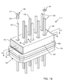
- FIG. 14 is a perspective view of a 9-lead feedthrough terminal assembly utilizing the contact spring of the present invention in its assembly;
- FIG. 15 is a sectional view taken generally along the line 15 — 15 of FIG. 14 , illustrating the configuration of ground electrode plates within the capacitor thereof;
- FIG. 16 is a sectional view taken generally along the line 16 — 16 of FIG. 14 , illustrating the configuration of active electrode plates within the capacitor;
- FIG. 17 is an enlarged perspective view of the conductive, resiliently flexible contact spring of the present invention.
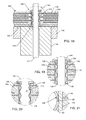
- FIG. 18 is a fragmented, enlarged sectional view taken generally along the line 18 — 18 of FIG. 14 , illustrating seating of the contact spring of FIG. 17 within the annular space between the inside diameter of the feedthrough capacitor and the outside diameter of the terminal pin;
- FIG. 19 is an enlarged sectional view of the area designated by the number 19 in FIG. 18 , illustrating an alternative construction of the contact spring of FIG. 17 ;
- FIG. 20 is a view similar to FIG. 19 , illustrating yet another alternative construction of the contact spring of FIG. 17 ;
- FIG. 21 is an enlarged, fragmented sectional view taken generally of the area indicated by the number 21 in FIG. 20 ;
- FIG. 22 is a sectional view similar to FIG. 18 , illustrating an alternative embodiment of the terminal pin subassembly.
- FIG. 23 is a sectional view similar to FIGS. 18 and 22 , illustrating yet another alternative embodiment.
- FIGS. 1–4 illustrate a prior art unipolar discoidal feedthrough capacitor 100 .
- the capacitor 100 is typically formed of a dielectric material 102 having disposed therein in an alternating fashion ground electrode plates 104 and active electrode plates 106 .
- a passageway 108 is provided through the capacitor 100 , which is lined with a metallization layer 110 , typically applied either by thick film processes or by selective electro-plating.
- the thick film process consists of a silver or silver palladium bearing glass frit which is placed and the fired onto the capacitor 100 .
- This internal metallization material 110 provides the electrical contact to the active electrode plate set 106 .
- Metallization 112 is applied about the periphery of the capacitor 100 in a similar manner as the interior metallization 110 .
- the exterior metallization 112 provides the electrical contact to the ground electrode plate set 104 .
- FIG. 5 is a cross-sectional view showing the discoidal feedthrough capacitor 100 of FIG. 1 mounted to an hermetic terminal assembly 114 of an active implantable medical device (AIMD).
- the assembly 114 shown in FIG. 5 is typical of most EMI filtered terminals for human implant applications.
- the terminal assembly 114 typically comprises a conductive ferrule 116 conductively and hermetically attached to a housing 118 of an AIMD by means of a laser weld 120 .
- a conductive terminal pin or lead 122 extends through the ferrule 116 in non-conductive relation by means of an alumina insulator 124 .
- An hermetic gold braze seal 126 is provided between the alumina insulator 124 and the ferrule 116 , and another gold braze seal 128 is provided between the terminal pin 122 and the insulator 124 . As shown, the hermetic seal 128 extends through the insulator 124 for contact with the interior metallization 110 on the capacitor 100 in a manner as described in detail on U.S. Pat. No. 6,765,779 (the contents of which are incorporated herein).
- a nonconductive, insulating washer 130 is disposed adjacent to an interior surface of the ferrule 116 and the alumina insulator 124 , and the capacitor 100 is placed adjacent to the insulating washer 130 such that the terminal pin 122 extends through the passageway 108 .
- the capacitor 100 is surface mounted, as shown in FIG. 5 , or embedded inside the ferrule 116 , there are still basic principles that apply. That is, there must be an electrical connection between the lead wire 122 and the inside diameter metallization 110 of the feedthrough capacitor 100 .
- This electrical connection material is usually a thermal-setting conductive polymer 132 such as a conductive polyimide, a solder, or the like. It is important that this material 132 be free of voids and flow down into the annular space between the lead wire/terminal pin 122 and the inside diameter (ID) of the feedthrough capacitor 100 . It is also important that this material not migrate or leak out between the capacitor 100 and the hermetic terminal 114 and thus short out to the ferrule 116 .
- the insulator washer 130 is added which adhesively attaches itself to both the feedthrough capacitor 100 and the mounting surface against the hermetic terminal 114 .
- This material forms a solid bond thereby preventing material 132 from migrating between the capacitor 100 and the mounting surface and causing short circuits.
- the placement of electrical material 132 involves the related steps of providing the insulating washer 130 and also a number of clean up steps involving multiple centrifuging of the material 132 followed by curing and cleaning by microblasting, as described above.
- An electrical connection is also required on the capacitor 100 between its outside diameter metallization 112 and the ferrule 116 . This is shown as material 134 and is also of the group of conductive thermal-setting polymers.
- FIGS. 6–13 illustrate several additional and different types of feedthrough terminal assemblies 214 and 314 which may advantageously utilize the conductive insert, usually in the form of a resiliently flexible contact spring 136 ( FIG. 17 ) of the present invention.
- FIG. 6 is a prior art terminal assembly 214 taken from U.S. Pat. No. 6,275,369. It has a capture flange 138 in order to facilitate the placement of thermal-setting conductive adhesive 134 disposed between the ferrule 116 and the outside diameter metallization 112 of the feedthrough capacitor 200 .
- FIG. 7 is the top view of the feedthrough filter assembly of FIG. 6 , illustrating that this is a quadpolar or four-terminal device.
- FIG. 8 is a perspective view of a bipolar internally grounded capacitor 300 in accordance with U.S. Pat. No. 5,905,627.
- FIGS. 9–11 illustrate the active electrode plates 106 of the capacitor 300 of FIG. 8 , and the ground electrode plates 104 . It is noteworthy that the ground electrode plates 104 do not extend to the outside or perimeter of the ceramic capacitor 300 .
- the capacitor 300 of FIG. 8 is designed for mounting onto a hermetic terminal subassembly 140 with a grounded pin 142 as shown in FIG. 12 .
- Pin 142 is solidly welded or brazed into the ferrule 116 of the hermetic terminal subassembly 140 .
- FIG. 13 shows the capacitor 300 of FIGS. 8–11 mounted to the ferrule of FIG. 12 .
- electrical connection material 132 has been placed to make electrical attachment to the capacitor inside diameter metallization 110 , 112 and each of the lead and ground wires 122 and 142 .
- an adhesively backed insulating washer 130 has been first disposed between the capacitor 300 and the ferrule 116 . This is important so that the electric connection material 132 does not leak out underneath the ceramic capacitor 300 and short over to the ferrule 116 .
- FIGS. 14–16 illustrate a novel 9-pole feedthrough terminal assembly 414 which utilizes the contact spring 136 of the present invention.
- the capacitor 400 shown in FIG. 14 is an externally grounded capacitor similar to FIGS. 1–7 but with more lead wires or terminal pins 122 .
- the ground electrode plates 104 extend to the outer edge of the capacitor 400 and are electrically coupled to the outer diameter or ground metallization 112 of the capacitor 400 .
- the outer diameter metallization 112 is in turn coupled to the ferrule 116 by electrical connection material 134 .
- the lead wires 122 pass through the ferrule 116 in insulative relationship.
- An insulating washer 130 is disposed between the capacitor 400 and the ferrule 116 or other mounting surface of the terminal assembly 414 , as has been described in prior art embodiments. Electrical contact between the capacitor inside diameter metallization 110 and the outside surface of the lead wires 122 is accomplished by inserting the contact spring 136 of the present invention as shown. An insertion tool (not shown) is used to slide the contact spring 136 down along the lead wire 122 and then ram it firmly into the space between the inside diameter metallization 110 and the lead wire 122 .
- the capacitor 400 is externally grounded such that the outer diameter metallization 112 is conductively coupled to the ground electrode plates 104 , as illustrated in FIG. 15 , which is in turn conductively coupled to the ferrule 116 by electrical connection material 134 .
- Electrical connection material 134 may be a thermal-setting conductive adhesive, a conductive polyimide, a solder, a braze or the like.
- the insulating washer 130 is fully or partially disposed between the capacitor 400 and the ferrule 116 or mounting surface of the terminal 414 and adhesively attaches itself to both the capacitor 400 and the ferrule 116 or mounting surface of the hermetic terminal 414 .
- the insulating washer 130 forms a solid bond thereby preventing electrical connection material 134 from migrating or leaking underneath the capacitor between the ferrule 116 to any of the active terminal pins 122 and causing short circuits.
- FIG. 15 illustrates the ground electrode plate set 104 of the capacitor 400 shown in FIG. 14
- FIG. 16 illustrates the active electrode plate sets 106 .
- the active electrode plates 106 are referred to as a first set of electrode plates
- the ground electrode plate set 104 are referred to as a second set of electrode plates.
- FIG. 17 is an enlarged perspective view of an insert 136 embodying the invention.
- the contact springs 136 are typically constructed of beryllium, beryllium copper, phosphor bronze, Nitinol or the like.
- Active implantable medical devices have both shock and vibration standards. For example, pacemakers must be able to withstand rough handling or even being dropped on the floor or street by a doctor. Shock standards vary between 1000 and 1500 Gs. Accordingly, referring now back to the structure shown in FIG. 14 , it is important that the feedthrough capacitor 400 be firmly retained by the insert contact springs 136 .
- the contact spring 136 be designed so that it firmly pinches down against lead and ground wires 122 and 142 . This is where the top head portion 144 of the contact spring 136 is very important. As long as the contact spring 136 grips very tightly on the lead wire 122 , then the flange or head 144 will retain the ceramic capacitor 400 such that it cannot come loose during shock and vibration loading. Said optional top head could be replaced by a subsequent epoxy “O-RING” or equivalent mechanical attachment.
- the insert spring 136 includes a plurality of legs 152 extending downwardly therefrom.
- These legs 152 are preferably comprised of a resiliently flexible material so as to have spring-like characteristics in order to be squeezed in the annular space between the terminal pin 122 and the inner aperture metallization 110 , as illustrated in FIG. 18 .
- the legs 152 are non-planar so as to facilitate physical contact between terminal pin 122 and the active electrode plates 106 , through the inner metallization 110 .
- insert 136 has been described as such, it will be readily understood by those skilled in the art that the inserts could be formed into various geometries, such as a spiral or helix spring, V-shape spring, etc.
- the important aspect of the insert 136 is that it form an electrical and mechanical connection between the terminal pin 122 and the internal metallization 110 .
- an adhesive may be used either in-lieu of or in combination with head portion 144 .
- an adhesive may be used either in-lieu of or in combination with head portion 144 .
- an optional epoxy pre-form 146 that can be dropped in place around two or three or even all of the lead wires 122 .
- This epoxy pre-form 146 is cured to form a bonding material between the lead wire 122 and the top 144 of the contact spring 136 . After curing, the epoxy material 146 establishes shear strength between the lead wires 122 and the contact spring 136 . This would act to improve the shock and vibration handling capability of the assembly.
- the insert 136 can be comprised of a memory shape alloy material, such that it has one shape at one temperature, and a completely different shape at a different temperature.
- Nitinol is such a memory shape material which can be designed such that the insert spring 136 can fit very loosely and slide into the angular space between the capacitor inside metallization 110 and outside diameter of the terminal pin 122 when either at an elevated temperature well above body temperature; or a lower temperature, preferably significantly below room temperature.
- the insert 136 fits very tightly between the terminal pin 122 and the capacitor 400 so as to establish a mechanical and electrical connection with the internal metallization 110 .
- FIG. 18 is an enlarged cross-sectional view taken from FIG. 14 .
- the contact spring 136 has been seated into the annular space between the inside diameter metallization 110 of the feedthrough capacitor 400 and the outside diameter of a terminal pin 122 .
- the legs 152 of the contact spring 132 solidly contact the outside diameter of the pin 122 and also solidly contact the inside diameter metallization 110 of the feedthrough capacitor 400 .
- FIG. 19 illustrates an alternative embodiment of the contact spring 136 previously described in FIGS. 17 and 18 .
- the bottom of the legs 152 of the contact spring 136 comes to sharp points 148 which dig into the lead wire 122 . This is to improve the shock and vibration loading characteristics of the assembly.
- FIGS. 20 and 21 illustrate yet a different embodiment of the contact spring 136 insert assembly previously described in FIGS. 17–19 .
- one or more sharp notches or barbs 150 have been formed in the legs 152 of the contact spring 136 .
- These sharp barbs 150 are designed to dig into the inside diameter metallization 110 of the feedthrough capacitor 400 .
- the barbs 150 are formed such that they permit the insertion of the insert spring 136 into the aperture, but impede removal of the insert 136 therefrom. If this type of contact spring 136 is used, this becomes a one-way insertion. That is, there would be no way to remove the ceramic capacitor 400 without breaking it. Usually, there is no reason to remove the feedthrough capacitor 400 once it is installed. It is generally more desirable to have the maximum resistance to both shock and vibration loads.
- FIG. 22 illustrates an alternative embodiment of the feedthrough capacitor terminal assembly 414 of FIG. 14 .
- the leads or terminal pins 122 have been cut off such that they do not extend above the feedthrough capacitor 100 .
- a modified contact spring 136 is shown inserted into the annular space between the inside diameter metallization 110 and the outside surface of the lead wire 122 .
- the head 144 of the contact spring 136 assembly has been enlarged and thickened to provide a convenient surface for wire bonding. Wire bond attachments by the customer are normally done by ultrasonic or thermal bonding techniques. In this case, it is desirable that the entire contact spring 136 be plated with an ultra pure or soft gold plating suitable for wire bonding.
- any of these wire bond pads could be integrated with the contact spring 136 as described herein.
- any of the substrates shown therein could be placed on top of the feedthrough capacitor 100 which will improve both the shock and vibration loading resistance. This is illustrated by FIG. 23 where one of the novel wire bond caps of pending U.S. patent application Ser. No. 10/812,967 is shown on top of the feedthrough capacitor 100 .
- a contact spring 136 has been placed between the capacitor inside diameter metallization 110 and the outside surface diameter of terminal pin 122 .
- the lead terminal pin 122 has been lengthened to protrude only slightly above the ceramic capacitor 100 .
- a wire bond pad 154 is shown disposed on top of the lead 122 .
- this wire bond pad 154 would be laser welded through a hole 156 to form laser weld material 158 which makes a very highly reliable mechanical and electrical connection between wire bond pad 154 and lead 122 . It would be preferable if this wire bond pad 154 were of Kovar or a similar alloy with ultra pure or soft gold plating.
- An optional connective material 160 is shown which connects the wire bond pad 154 to the contact spring top head portion 144 .
- the contact spring 136 does not need to withstand high shock and vibration loads. This is because the mass of the ceramic capacitor 100 is firmly retained by the laser weld connection 158 .
- a contact spring 136 could be used which does not have to dig into the terminal pin 122 .
- the lead wire 122 would have to be pretreated either by plating, sputtering, plasma arc deposition or the like, such that it was over coated with a conductive but non-oxidizable material such as silver or gold, which would make a reliable electrical connection to the contact spring 136 .
- the present invention provides a manufacturing methodology which advantageously renders itself to high volume manufacturing techniques by eliminating many of the labor-intensive manufacturing steps. This eliminates all the steps including centrifuging.
- Those skilled in the art will realize that there are a number of ways to design springs and inserts through more reliable electrical connections between the capacitor plates 104 or 106 and the terminal pins 122 or 142 .
Landscapes
- Engineering & Computer Science (AREA)
- Power Engineering (AREA)
- Manufacturing & Machinery (AREA)
- Microelectronics & Electronic Packaging (AREA)
- Electrotherapy Devices (AREA)
Abstract
Description
Claims (42)
Priority Applications (1)
| Application Number | Priority Date | Filing Date | Title |
|---|---|---|---|
| US11/163,198 US7136273B2 (en) | 2005-03-30 | 2005-10-10 | Hybrid spring contact system for EMI filtered hermetic seals for active implantable medical devices |
Applications Claiming Priority (2)
| Application Number | Priority Date | Filing Date | Title |
|---|---|---|---|
| US10/907,361 US6987660B2 (en) | 2003-02-27 | 2005-03-30 | Spring contact system for EMI filtered hermetic seals for active implantable medical devices |
| US11/163,198 US7136273B2 (en) | 2005-03-30 | 2005-10-10 | Hybrid spring contact system for EMI filtered hermetic seals for active implantable medical devices |
Related Parent Applications (1)
| Application Number | Title | Priority Date | Filing Date |
|---|---|---|---|
| US10/907,361 Continuation-In-Part US6987660B2 (en) | 2003-02-27 | 2005-03-30 | Spring contact system for EMI filtered hermetic seals for active implantable medical devices |
Publications (2)
| Publication Number | Publication Date |
|---|---|
| US20060221543A1 US20060221543A1 (en) | 2006-10-05 |
| US7136273B2 true US7136273B2 (en) | 2006-11-14 |
Family
ID=37070114
Family Applications (1)
| Application Number | Title | Priority Date | Filing Date |
|---|---|---|---|
| US11/163,198 Expired - Lifetime US7136273B2 (en) | 2005-03-30 | 2005-10-10 | Hybrid spring contact system for EMI filtered hermetic seals for active implantable medical devices |
Country Status (1)
| Country | Link |
|---|---|
| US (1) | US7136273B2 (en) |
Cited By (54)
| Publication number | Priority date | Publication date | Assignee | Title |
|---|---|---|---|---|
| US20060259093A1 (en) * | 2003-02-27 | 2006-11-16 | Greatbatch-Sierra, Inc. | Hermetic feedthrough terminal assembly with wire bond pads for human implant applications |
| US7306490B1 (en) * | 2007-04-05 | 2007-12-11 | Delphi Technologies, Inc. | High-density pass-through filter apparatus |
| US20080039709A1 (en) * | 2004-08-09 | 2008-02-14 | Karmarkar Parag V | Implantable Mri compatible Stimulation Leads And Antennas And Related Systems And Methods |
| US20080097193A1 (en) * | 2004-07-27 | 2008-04-24 | Karmarkar Parag V | Mri Systems Having Mri Compatible Universal Delivery Cannulas With Cooperating Mri Antenna Probes and Related Systems and Methods |
| US20080119919A1 (en) * | 2001-04-13 | 2008-05-22 | Surgi-Vision, Inc. | Mri compatible medical leads with band stop filters |
| US20080243218A1 (en) * | 2007-03-19 | 2008-10-02 | Bottomley Paul A | Mri and rf compatible leads and related methods of operating and fabricating leads |
| US20080262584A1 (en) * | 2007-03-19 | 2008-10-23 | Bottomley Paul A | Methods and apparatus for fabricating leads with conductors and related flexible lead configurations |
| US20090171421A1 (en) * | 2005-10-21 | 2009-07-02 | Ergin Atalar | Mri-safe high impedance lead systems |
| US20090288869A1 (en) * | 2008-05-24 | 2009-11-26 | International Business Machines Corporation | Curvilinear wiring structure to reduce areas of high field density in an integrated circuit |
| US20110170230A1 (en) * | 2007-03-21 | 2011-07-14 | Medtronic, Inc. | Filtering Capacitor Feedthrough Assembly |
| US20110218422A1 (en) * | 2005-05-04 | 2011-09-08 | Surgivision, Inc. | Electrical lead for an electronic device such as an implantable device |
| US8219208B2 (en) | 2001-04-13 | 2012-07-10 | Greatbatch Ltd. | Frequency selective passive component networks for active implantable medical devices utilizing an energy dissipating surface |
| DE102011009856A1 (en) | 2011-01-31 | 2012-08-02 | W.C. Heraeus Gmbh | An electrical feedthrough and method of making a lead-containing feedthrough for a medically implantable device |
| DE102011009857A1 (en) | 2011-01-31 | 2012-08-02 | Heraeus Precious Metals Gmbh & Co. Kg | Electrical feedthrough with a cermet-like connector for an active implantable medical device |
| DE102011009863A1 (en) | 2011-01-31 | 2012-08-02 | Heraeus Precious Metals Gmbh & Co. Kg | Ceramic bushing with conductive elements of high conductivity |
| DE102011009861A1 (en) | 2011-01-31 | 2012-08-02 | Heraeus Precious Metals Gmbh & Co. Kg | Process for the preparation of a cermet-containing feedthrough |
| DE102011009865A1 (en) | 2011-01-31 | 2012-08-02 | Heraeus Precious Metals Gmbh & Co. Kg | Headboard for a medically implantable device |
| DE102011009867A1 (en) | 2011-01-31 | 2012-08-02 | Heraeus Precious Metals Gmbh & Co. Kg | Ceramic bushing for a medically implantable device |
| DE102011009859A1 (en) | 2011-01-31 | 2012-08-02 | Heraeus Precious Metals Gmbh & Co. Kg | Ceramic bushing with filter |
| DE102011009862A1 (en) | 2011-01-31 | 2012-08-02 | Heraeus Precious Metals Gmbh & Co. Kg | Cermet-containing bushing with holding element for a medically implantable device |
| DE102011009855A1 (en) | 2011-01-31 | 2012-08-02 | Heraeus Precious Metals Gmbh & Co. Kg | Ceramic bushing with inductive filter |
| DE102011009866A1 (en) | 2011-01-31 | 2012-08-02 | Heraeus Precious Metals Gmbh & Co. Kg | Directly applied electrical feedthrough |
| DE102011009858A1 (en) | 2011-01-31 | 2012-08-02 | Heraeus Precious Metals Gmbh & Co. Kg | Cermet-containing bushing for a medically implantable device with a bonding layer |
| DE102011009860A1 (en) | 2011-01-31 | 2012-08-02 | Heraeus Precious Metals Gmbh & Co. Kg | Implantable device with integrated ceramic bushing |
| US8275466B2 (en) | 2006-06-08 | 2012-09-25 | Greatbatch Ltd. | Band stop filter employing a capacitor and an inductor tank circuit to enhance MRI compatibility of active medical devices |
| DE102011119125A1 (en) | 2011-11-23 | 2013-05-23 | Heraeus Precious Metals Gmbh & Co. Kg | Contacting arrangement with bushing and filter structure |
| EP2617461A1 (en) | 2012-01-16 | 2013-07-24 | Greatbatch Ltd. | Co-fired hermetically sealed feedthrough with alumina substrate and platinum filled via for an active implantable medical device |
| US9403023B2 (en) | 2013-08-07 | 2016-08-02 | Heraeus Deutschland GmbH & Co. KG | Method of forming feedthrough with integrated brazeless ferrule |
| US9431801B2 (en) | 2013-05-24 | 2016-08-30 | Heraeus Deutschland GmbH & Co. KG | Method of coupling a feedthrough assembly for an implantable medical device |
| US9478959B2 (en) | 2013-03-14 | 2016-10-25 | Heraeus Deutschland GmbH & Co. KG | Laser welding a feedthrough |
| US9504841B2 (en) | 2013-12-12 | 2016-11-29 | Heraeus Deutschland GmbH & Co. KG | Direct integration of feedthrough to implantable medical device housing with ultrasonic welding |
| US9610451B2 (en) | 2013-12-12 | 2017-04-04 | Heraeus Deutschland GmbH & Co. KG | Direct integration of feedthrough to implantable medical device housing using a gold alloy |
| US9610452B2 (en) | 2013-12-12 | 2017-04-04 | Heraeus Deutschland GmbH & Co. KG | Direct integration of feedthrough to implantable medical device housing by sintering |
| EP3228354A1 (en) | 2016-04-07 | 2017-10-11 | Heraeus Deutschland GmbH & Co. KG | Feedthrough with a cermet conductor and a method of connecting a wire to a feedthrough |
| EP3320950A1 (en) | 2016-11-10 | 2018-05-16 | Greatbatch Ltd. | Feedthrough assembly for active implantable medical device |
| EP3326692A1 (en) | 2016-11-08 | 2018-05-30 | Greatbatch Ltd. | Feedthrough for an implantable medical device having a composite conductive lead |
| EP3345652A1 (en) | 2017-01-06 | 2018-07-11 | Greatbatch Ltd. | Method for manufacturing a feedthrough for an active implantable medical device |
| US10154616B2 (en) | 2012-09-05 | 2018-12-11 | Avx Corporation | Electromagnetic interference filter for implanted electronics |
| EP3449973A1 (en) | 2017-08-30 | 2019-03-06 | Greatbatch Ltd. | Hermetically sealed filtered feedthrough assembly |
| US10249415B2 (en) | 2017-01-06 | 2019-04-02 | Greatbatch Ltd. | Process for manufacturing a leadless feedthrough for an active implantable medical device |
| US10283275B2 (en) | 2016-05-20 | 2019-05-07 | Greatbatch Ltd. | Feedthrough seal apparatus, system, and method |
| US10350421B2 (en) | 2013-06-30 | 2019-07-16 | Greatbatch Ltd. | Metallurgically bonded gold pocket pad for grounding an EMI filter to a hermetic terminal for an active implantable medical device |
| US10363425B2 (en) | 2015-06-01 | 2019-07-30 | Avx Corporation | Discrete cofired feedthrough filter for medical implanted devices |
| US10449375B2 (en) | 2016-12-22 | 2019-10-22 | Greatbatch Ltd. | Hermetic terminal for an AIMD having a pin joint in a feedthrough capacitor or circuit board |
| US10561837B2 (en) | 2011-03-01 | 2020-02-18 | Greatbatch Ltd. | Low equivalent series resistance RF filter for an active implantable medical device utilizing a ceramic reinforced metal composite filled via |
| US10874865B2 (en) | 2017-11-06 | 2020-12-29 | Avx Corporation | EMI feedthrough filter terminal assembly containing a resin coating over a hermetically sealing material |
| US10905888B2 (en) | 2018-03-22 | 2021-02-02 | Greatbatch Ltd. | Electrical connection for an AIMD EMI filter utilizing an anisotropic conductive layer |
| US10912945B2 (en) | 2018-03-22 | 2021-02-09 | Greatbatch Ltd. | Hermetic terminal for an active implantable medical device having a feedthrough capacitor partially overhanging a ferrule for high effective capacitance area |
| US20210051812A1 (en) * | 2014-12-24 | 2021-02-18 | Medtronic, Inc. | Hermetically-sealed packages including feedthrough assemblies |
| US11198014B2 (en) | 2011-03-01 | 2021-12-14 | Greatbatch Ltd. | Hermetically sealed filtered feedthrough assembly having a capacitor with an oxide resistant electrical connection to an active implantable medical device housing |
| US11351387B2 (en) | 2012-01-16 | 2022-06-07 | Greatbatch Ltd. | Method of manufacturing a singulated feedthrough insulator for a hermetic seal of an active implantable medical device incorporating a post conductive paste filled pressing step |
| US11701519B2 (en) | 2020-02-21 | 2023-07-18 | Heraeus Medical Components Llc | Ferrule with strain relief spacer for implantable medical device |
| US11894163B2 (en) | 2020-02-21 | 2024-02-06 | Heraeus Medical Components Llc | Ferrule for non-planar medical device housing |
| US12576279B2 (en) | 2022-01-03 | 2026-03-17 | Axonics, Inc. | Header for a neurostimulator |
Families Citing this family (23)
| Publication number | Priority date | Publication date | Assignee | Title |
|---|---|---|---|---|
| US7502217B2 (en) * | 2007-02-16 | 2009-03-10 | Medtronic, Inc. | Filtering capacitor feedthrough assembly |
| US10080889B2 (en) | 2009-03-19 | 2018-09-25 | Greatbatch Ltd. | Low inductance and low resistance hermetically sealed filtered feedthrough for an AIMD |
| DE102009011479A1 (en) * | 2009-03-06 | 2010-09-09 | Olympus Winter & Ibe Gmbh | Surgical instrument |
| US20120256704A1 (en) * | 2011-03-01 | 2012-10-11 | Greatbatch Ltd. | Rf filter for an active medical device (amd) for handling high rf power induced in an associated implanted lead from an external rf field |
| US8154846B2 (en) * | 2009-06-02 | 2012-04-10 | Astec International Limited | Feedthrough capacitor assemblies |
| DE102009045106A1 (en) * | 2009-09-29 | 2011-03-31 | Robert Bosch Gmbh | Through capacitor |
| US9320910B2 (en) | 2010-03-31 | 2016-04-26 | Advanced Neuromodulation Systems, Inc. | Method of fabricating implantable pulse generator using wire connections to feedthrough structures and implantable pulse generators |
| US8726499B2 (en) | 2010-03-31 | 2014-05-20 | Advanced Neuromodulation Systems, Inc. | Method of fabricating implantable pulse generator using wire connections to feedthrough structures |
| US8816242B2 (en) | 2010-03-31 | 2014-08-26 | Advanced Neuromodulation Systems, Inc. | Method of fabricating implantable pulse generator using wire connections to feedthrough structures and implantable pulse generators |
| WO2011123627A1 (en) * | 2010-03-31 | 2011-10-06 | Advanced Neuromodulation Systems, Inc. | Method of fabricating implantable pulse generator using wire connections to feedthrough structures and implantable pulse generators |
| US9757558B2 (en) | 2011-03-01 | 2017-09-12 | Greatbatch Ltd. | RF filter for an active medical device (AMD) for handling high RF power induced in an associated implanted lead from an external RF field |
| US9931514B2 (en) | 2013-06-30 | 2018-04-03 | Greatbatch Ltd. | Low impedance oxide resistant grounded capacitor for an AIMD |
| US9427596B2 (en) | 2013-01-16 | 2016-08-30 | Greatbatch Ltd. | Low impedance oxide resistant grounded capacitor for an AIMD |
| EP2529790B1 (en) * | 2011-06-03 | 2017-09-20 | Greatbatch Ltd. | Feedthrough wire connector for use in a medical device |
| US9692173B2 (en) | 2011-06-03 | 2017-06-27 | Greatbatch Ltd. | Feedthrough wire connector for use in a medical device |
| US11211741B2 (en) | 2011-06-03 | 2021-12-28 | Greatbatch Ltd. | Removable terminal pin connector for an active electronics circuit board for use in an implantable medical device |
| US8593816B2 (en) | 2011-09-21 | 2013-11-26 | Medtronic, Inc. | Compact connector assembly for implantable medical device |
| USRE46699E1 (en) | 2013-01-16 | 2018-02-06 | Greatbatch Ltd. | Low impedance oxide resistant grounded capacitor for an AIMD |
| US9138821B2 (en) * | 2014-01-17 | 2015-09-22 | Medtronic, Inc. | Methods for simultaneously brazing a ferrule and lead pins |
| KR102086481B1 (en) * | 2014-04-16 | 2020-03-09 | 삼성전기주식회사 | Multi layer ceramic capacitor and circuit board for mounting the same |
| US10433737B2 (en) * | 2017-01-27 | 2019-10-08 | Medtronic, Inc. | Medical device including feedthrough assembly |
| GB2574653B (en) | 2018-06-14 | 2020-09-09 | Knowles (Uk) Ltd | Capacitor having an electrical termination |
| US12218458B2 (en) | 2020-03-05 | 2025-02-04 | Greatbatch Ltd. | High-voltage electrical insulation for use in active implantable medical devices circuit board connectors |
Citations (8)
| Publication number | Priority date | Publication date | Assignee | Title |
|---|---|---|---|---|
| US5333095A (en) | 1993-05-03 | 1994-07-26 | Maxwell Laboratories, Inc., Sierra Capacitor Filter Division | Feedthrough filter capacitor assembly for human implant |
| US5905627A (en) | 1997-09-10 | 1999-05-18 | Maxwell Energy Products, Inc. | Internally grounded feedthrough filter capacitor |
| US6275369B1 (en) | 1997-11-13 | 2001-08-14 | Robert A. Stevenson | EMI filter feedthough terminal assembly having a capture flange to facilitate automated assembly |
| US6529103B1 (en) * | 2000-09-07 | 2003-03-04 | Greatbatch-Sierra, Inc. | Internally grounded feedthrough filter capacitor with improved ground plane design for human implant and other applications |
| US20040258392A1 (en) | 2003-04-14 | 2004-12-23 | Sony Corporation | Information processing apparatus for detecting inter-track boundaries |
| US6985347B2 (en) * | 2002-02-28 | 2006-01-10 | Greatbatch-Sierra, Inc. | EMI filter capacitors designed for direct body fluid exposure |
| US6987660B2 (en) * | 2003-02-27 | 2006-01-17 | Greatbatch-Sierra, Inc. | Spring contact system for EMI filtered hermetic seals for active implantable medical devices |
| US7064270B2 (en) * | 2003-10-29 | 2006-06-20 | Medtronic, Inc. | Implantable device feedthrough assembly |
-
2005
- 2005-10-10 US US11/163,198 patent/US7136273B2/en not_active Expired - Lifetime
Patent Citations (9)
| Publication number | Priority date | Publication date | Assignee | Title |
|---|---|---|---|---|
| US5333095A (en) | 1993-05-03 | 1994-07-26 | Maxwell Laboratories, Inc., Sierra Capacitor Filter Division | Feedthrough filter capacitor assembly for human implant |
| US5905627A (en) | 1997-09-10 | 1999-05-18 | Maxwell Energy Products, Inc. | Internally grounded feedthrough filter capacitor |
| US6275369B1 (en) | 1997-11-13 | 2001-08-14 | Robert A. Stevenson | EMI filter feedthough terminal assembly having a capture flange to facilitate automated assembly |
| US6529103B1 (en) * | 2000-09-07 | 2003-03-04 | Greatbatch-Sierra, Inc. | Internally grounded feedthrough filter capacitor with improved ground plane design for human implant and other applications |
| US6566978B2 (en) * | 2000-09-07 | 2003-05-20 | Greatbatch-Sierra, Inc. | Feedthrough capacitor filter assemblies with leak detection vents |
| US6985347B2 (en) * | 2002-02-28 | 2006-01-10 | Greatbatch-Sierra, Inc. | EMI filter capacitors designed for direct body fluid exposure |
| US6987660B2 (en) * | 2003-02-27 | 2006-01-17 | Greatbatch-Sierra, Inc. | Spring contact system for EMI filtered hermetic seals for active implantable medical devices |
| US20040258392A1 (en) | 2003-04-14 | 2004-12-23 | Sony Corporation | Information processing apparatus for detecting inter-track boundaries |
| US7064270B2 (en) * | 2003-10-29 | 2006-06-20 | Medtronic, Inc. | Implantable device feedthrough assembly |
Cited By (112)
| Publication number | Priority date | Publication date | Assignee | Title |
|---|---|---|---|---|
| US20080119919A1 (en) * | 2001-04-13 | 2008-05-22 | Surgi-Vision, Inc. | Mri compatible medical leads with band stop filters |
| US8219208B2 (en) | 2001-04-13 | 2012-07-10 | Greatbatch Ltd. | Frequency selective passive component networks for active implantable medical devices utilizing an energy dissipating surface |
| US20060259093A1 (en) * | 2003-02-27 | 2006-11-16 | Greatbatch-Sierra, Inc. | Hermetic feedthrough terminal assembly with wire bond pads for human implant applications |
| US7623335B2 (en) * | 2003-02-27 | 2009-11-24 | Greatbatch-Sierra, Inc | Hermetic feedthrough terminal assembly with wire bond pads for human implant applications |
| US20080097193A1 (en) * | 2004-07-27 | 2008-04-24 | Karmarkar Parag V | Mri Systems Having Mri Compatible Universal Delivery Cannulas With Cooperating Mri Antenna Probes and Related Systems and Methods |
| US8108028B2 (en) | 2004-07-27 | 2012-01-31 | Surgi-Vision Inc. | MRI systems having MRI compatible universal delivery cannulas with cooperating MRI antenna probes and related systems and methods |
| US20080039709A1 (en) * | 2004-08-09 | 2008-02-14 | Karmarkar Parag V | Implantable Mri compatible Stimulation Leads And Antennas And Related Systems And Methods |
| US8509876B2 (en) | 2004-08-09 | 2013-08-13 | The Johns Hopkins University | Implantable MRI compatible stimulation leads and antennas and related systems and methods |
| US20110218422A1 (en) * | 2005-05-04 | 2011-09-08 | Surgivision, Inc. | Electrical lead for an electronic device such as an implantable device |
| US8380277B2 (en) | 2005-05-04 | 2013-02-19 | MRI Interventions, Inc. | Electrical lead for an electronic device such as an implantable device |
| US8649842B2 (en) | 2005-05-04 | 2014-02-11 | Boston Scientific Neuromodulation Corporation | Electrical lead for an electronic device such as an implantable device |
| US20090171421A1 (en) * | 2005-10-21 | 2009-07-02 | Ergin Atalar | Mri-safe high impedance lead systems |
| US8433421B2 (en) | 2005-10-21 | 2013-04-30 | Boston Scientific Neuromodulation Corporation | MRI-safe high impedance lead systems |
| US8688226B2 (en) | 2005-10-21 | 2014-04-01 | Boston Scientific Neuromodulation Corporation | MRI-safe high impedance lead systems |
| US8055351B2 (en) | 2005-10-21 | 2011-11-08 | Boston Scientific Neuromodulation Corporation | MRI-safe high impedance lead systems |
| US8275466B2 (en) | 2006-06-08 | 2012-09-25 | Greatbatch Ltd. | Band stop filter employing a capacitor and an inductor tank circuit to enhance MRI compatibility of active medical devices |
| US9119968B2 (en) | 2006-06-08 | 2015-09-01 | Greatbatch Ltd. | Band stop filter employing a capacitor and an inductor tank circuit to enhance MRI compatibility of active medical devices |
| US9248270B2 (en) | 2007-03-19 | 2016-02-02 | Boston Scientific Neuromodulation Corporation | Methods and apparatus for fabricating leads with conductors and related flexible |
| US9492651B2 (en) | 2007-03-19 | 2016-11-15 | MRI Interventions, Inc. | MRI and RF compatible leads and related methods of operating and fabricating leads |
| US9630000B2 (en) | 2007-03-19 | 2017-04-25 | Boston Scientific Neuromodulation Corporation | Methods and apparatus for fabricating leads with conductors and related flexible lead configurations |
| US10391307B2 (en) | 2007-03-19 | 2019-08-27 | Boston Scientific Neuromodulation Corporation | MRI and RF compatible leads and related methods of operating and fabricating leads |
| US20080262584A1 (en) * | 2007-03-19 | 2008-10-23 | Bottomley Paul A | Methods and apparatus for fabricating leads with conductors and related flexible lead configurations |
| US20080243218A1 (en) * | 2007-03-19 | 2008-10-02 | Bottomley Paul A | Mri and rf compatible leads and related methods of operating and fabricating leads |
| US8478409B2 (en) | 2007-03-21 | 2013-07-02 | Medtronic, Inc. | Filtering capacitor feedthrough assembly |
| US20110170230A1 (en) * | 2007-03-21 | 2011-07-14 | Medtronic, Inc. | Filtering Capacitor Feedthrough Assembly |
| US7306490B1 (en) * | 2007-04-05 | 2007-12-11 | Delphi Technologies, Inc. | High-density pass-through filter apparatus |
| US9275951B2 (en) | 2008-05-24 | 2016-03-01 | Globalfoundries Inc. | Curvilinear wiring structure to reduce areas of high field density in an integrated circuit |
| US20090288869A1 (en) * | 2008-05-24 | 2009-11-26 | International Business Machines Corporation | Curvilinear wiring structure to reduce areas of high field density in an integrated circuit |
| US8530970B2 (en) * | 2008-05-24 | 2013-09-10 | International Business Machines Corporation | Curvilinear wiring structure to reduce areas of high field density in an integrated circuit |
| US9504840B2 (en) | 2011-01-31 | 2016-11-29 | Heraeus Deutschland GmbH & Co. KG | Method of forming a cermet-containing bushing for an implantable medical device having a connecting layer |
| US9126053B2 (en) | 2011-01-31 | 2015-09-08 | Heraeus Precious Metals Gmbh & Co. Kg | Electrical bushing with cermet-containing connecting element for an active implantable medical device |
| DE102011009856A1 (en) | 2011-01-31 | 2012-08-02 | W.C. Heraeus Gmbh | An electrical feedthrough and method of making a lead-containing feedthrough for a medically implantable device |
| DE102011009860A1 (en) | 2011-01-31 | 2012-08-02 | Heraeus Precious Metals Gmbh & Co. Kg | Implantable device with integrated ceramic bushing |
| DE102011009857A1 (en) | 2011-01-31 | 2012-08-02 | Heraeus Precious Metals Gmbh & Co. Kg | Electrical feedthrough with a cermet-like connector for an active implantable medical device |
| DE102011009858A1 (en) | 2011-01-31 | 2012-08-02 | Heraeus Precious Metals Gmbh & Co. Kg | Cermet-containing bushing for a medically implantable device with a bonding layer |
| US9552899B2 (en) | 2011-01-31 | 2017-01-24 | Heraeus Deutschland GmbH & Co. KG | Ceramic bushing for an implantable medical device |
| DE102011009866A1 (en) | 2011-01-31 | 2012-08-02 | Heraeus Precious Metals Gmbh & Co. Kg | Directly applied electrical feedthrough |
| US9509272B2 (en) | 2011-01-31 | 2016-11-29 | Heraeus Deutschland GmbH & Co. KG | Ceramic bushing with filter |
| DE102011009855A1 (en) | 2011-01-31 | 2012-08-02 | Heraeus Precious Metals Gmbh & Co. Kg | Ceramic bushing with inductive filter |
| DE102011009862A1 (en) | 2011-01-31 | 2012-08-02 | Heraeus Precious Metals Gmbh & Co. Kg | Cermet-containing bushing with holding element for a medically implantable device |
| US8742268B2 (en) | 2011-01-31 | 2014-06-03 | Heraeus Precious Metals Gmbh & Co. Kg | Head part for an implantable medical device |
| US8825162B2 (en) | 2011-01-31 | 2014-09-02 | Heraeus Precious Metals Gmbh & Co. Kg | Ceramic bushing with inductive filter |
| US8894914B2 (en) | 2011-01-31 | 2014-11-25 | Heraeus Precious Metals Gmbh & Co. | Method for the manufacture of a cermet-containing bushing |
| US9032614B2 (en) | 2011-01-31 | 2015-05-19 | Heraeus Precious Metals Gmbh & Co. Kg | Method for manufacturing an electrical bushing for an implantable medical device |
| US9040819B2 (en) | 2011-01-31 | 2015-05-26 | Heraeus Precious Metals Gmbh & Co. Kg | Implantable device having an integrated ceramic bushing |
| US9048608B2 (en) | 2011-01-31 | 2015-06-02 | Heraeus Precious Metals Gmbh & Co. Kg | Method for the manufacture of a cermet-containing bushing for an implantable medical device |
| US9088093B2 (en) | 2011-01-31 | 2015-07-21 | Heraeus Precious Metals Gmbh & Co. Kg | Head part for an implantable medical device |
| DE102011009859A1 (en) | 2011-01-31 | 2012-08-02 | Heraeus Precious Metals Gmbh & Co. Kg | Ceramic bushing with filter |
| DE102011009863A1 (en) | 2011-01-31 | 2012-08-02 | Heraeus Precious Metals Gmbh & Co. Kg | Ceramic bushing with conductive elements of high conductivity |
| DE102011009867A1 (en) | 2011-01-31 | 2012-08-02 | Heraeus Precious Metals Gmbh & Co. Kg | Ceramic bushing for a medically implantable device |
| DE102011009865A1 (en) | 2011-01-31 | 2012-08-02 | Heraeus Precious Metals Gmbh & Co. Kg | Headboard for a medically implantable device |
| US9306318B2 (en) | 2011-01-31 | 2016-04-05 | Heraeus Deutschland GmbH & Co. KG | Ceramic bushing with filter |
| DE102011009861A1 (en) | 2011-01-31 | 2012-08-02 | Heraeus Precious Metals Gmbh & Co. Kg | Process for the preparation of a cermet-containing feedthrough |
| US10596369B2 (en) | 2011-03-01 | 2020-03-24 | Greatbatch Ltd. | Low equivalent series resistance RF filter for an active implantable medical device |
| US11198014B2 (en) | 2011-03-01 | 2021-12-14 | Greatbatch Ltd. | Hermetically sealed filtered feedthrough assembly having a capacitor with an oxide resistant electrical connection to an active implantable medical device housing |
| US10561837B2 (en) | 2011-03-01 | 2020-02-18 | Greatbatch Ltd. | Low equivalent series resistance RF filter for an active implantable medical device utilizing a ceramic reinforced metal composite filled via |
| US11071858B2 (en) | 2011-03-01 | 2021-07-27 | Greatbatch Ltd. | Hermetically sealed filtered feedthrough having platinum sealed directly to the insulator in a via hole |
| US11344734B2 (en) | 2011-03-01 | 2022-05-31 | Greatbatch Ltd. | Filtered feedthrough assembly having a capacitor ground metallization electrically connected to the gold braze portion sealing a ferrule peninsula to a matching insulator cutout |
| US10092766B2 (en) | 2011-11-23 | 2018-10-09 | Heraeus Deutschland GmbH & Co. KG | Capacitor and method to manufacture the capacitor |
| WO2013075797A1 (en) | 2011-11-23 | 2013-05-30 | Heraeus Precious Metals Gmbh & Co. Kg | Contacting arrangement comprising a feedthrough device and a filter structure |
| DE102011119125A1 (en) | 2011-11-23 | 2013-05-23 | Heraeus Precious Metals Gmbh & Co. Kg | Contacting arrangement with bushing and filter structure |
| EP2628504A1 (en) | 2012-01-16 | 2013-08-21 | Greatbatch Ltd. | EMI filtered co-connected hermetic feedthrough, feedthrough capacitor and leadwire assembly for an active implantable medical device |
| EP2617461A1 (en) | 2012-01-16 | 2013-07-24 | Greatbatch Ltd. | Co-fired hermetically sealed feedthrough with alumina substrate and platinum filled via for an active implantable medical device |
| EP2636427A1 (en) | 2012-01-16 | 2013-09-11 | Greatbatch Ltd. | Elevated hermetic feedthrough insulator adapted for side attachment of electrical conductors on the body fluid side of an active implantable medical device |
| EP3366348A1 (en) | 2012-01-16 | 2018-08-29 | Greatbatch Ltd. | Emi filtered co-connected hermetic feedthrough, feedthrough capacitor and leadwire assembly for an active implantable medical device |
| US11351387B2 (en) | 2012-01-16 | 2022-06-07 | Greatbatch Ltd. | Method of manufacturing a singulated feedthrough insulator for a hermetic seal of an active implantable medical device incorporating a post conductive paste filled pressing step |
| US10154616B2 (en) | 2012-09-05 | 2018-12-11 | Avx Corporation | Electromagnetic interference filter for implanted electronics |
| US10770879B2 (en) | 2013-03-14 | 2020-09-08 | Heraeus Deutschland GmbH & Co. KG | Welded feedthrough |
| US9478959B2 (en) | 2013-03-14 | 2016-10-25 | Heraeus Deutschland GmbH & Co. KG | Laser welding a feedthrough |
| US10418798B2 (en) | 2013-03-14 | 2019-09-17 | Heraeus Deutschland GmbH & Co. KG | Welded feedthrough |
| US9431801B2 (en) | 2013-05-24 | 2016-08-30 | Heraeus Deutschland GmbH & Co. KG | Method of coupling a feedthrough assembly for an implantable medical device |
| US9653893B2 (en) | 2013-05-24 | 2017-05-16 | Heraeus Deutschland GmbH & Co. KG | Ceramic feedthrough brazed to an implantable medical device housing |
| US10350421B2 (en) | 2013-06-30 | 2019-07-16 | Greatbatch Ltd. | Metallurgically bonded gold pocket pad for grounding an EMI filter to a hermetic terminal for an active implantable medical device |
| US9403023B2 (en) | 2013-08-07 | 2016-08-02 | Heraeus Deutschland GmbH & Co. KG | Method of forming feedthrough with integrated brazeless ferrule |
| US9814891B2 (en) | 2013-08-07 | 2017-11-14 | Heraeus Duetschland Gmbh & Co. Kg | Feedthrough with integrated brazeless ferrule |
| US9610452B2 (en) | 2013-12-12 | 2017-04-04 | Heraeus Deutschland GmbH & Co. KG | Direct integration of feedthrough to implantable medical device housing by sintering |
| US9849296B2 (en) | 2013-12-12 | 2017-12-26 | Heraeus Deutschland GmbH & Co. KG | Directly integrated feedthrough to implantable medical device housing |
| US9855008B2 (en) | 2013-12-12 | 2018-01-02 | Heraeus Deutschland GmbH & Co. LG | Direct integration of feedthrough to implantable medical device housing with ultrasonic welding |
| US9504841B2 (en) | 2013-12-12 | 2016-11-29 | Heraeus Deutschland GmbH & Co. KG | Direct integration of feedthrough to implantable medical device housing with ultrasonic welding |
| US9610451B2 (en) | 2013-12-12 | 2017-04-04 | Heraeus Deutschland GmbH & Co. KG | Direct integration of feedthrough to implantable medical device housing using a gold alloy |
| US20210051812A1 (en) * | 2014-12-24 | 2021-02-18 | Medtronic, Inc. | Hermetically-sealed packages including feedthrough assemblies |
| US11950387B2 (en) * | 2014-12-24 | 2024-04-02 | Medtronic, Inc. | Methods for forming hermetically-sealed packages including feedthrough assemblies |
| US20240244782A1 (en) * | 2014-12-24 | 2024-07-18 | Medtronic, Inc. | Hermetically-sealed packages including feedthrough assemblies |
| US11160988B2 (en) | 2015-06-01 | 2021-11-02 | Avx Corporation | Discrete cofired feedthrough filter for medical implanted devices |
| US10363425B2 (en) | 2015-06-01 | 2019-07-30 | Avx Corporation | Discrete cofired feedthrough filter for medical implanted devices |
| US10293172B2 (en) | 2016-04-07 | 2019-05-21 | Heraeus Deutschland GmbH & Co. KG | Method of connecting a wire to a feedthrough |
| EP3228354A1 (en) | 2016-04-07 | 2017-10-11 | Heraeus Deutschland GmbH & Co. KG | Feedthrough with a cermet conductor and a method of connecting a wire to a feedthrough |
| US10283275B2 (en) | 2016-05-20 | 2019-05-07 | Greatbatch Ltd. | Feedthrough seal apparatus, system, and method |
| EP3520857A1 (en) | 2016-11-08 | 2019-08-07 | Greatbatch Ltd. | Circuit board mounted filtered feedthrough assembly having a composite conductive lead for an aimd |
| EP3326692A1 (en) | 2016-11-08 | 2018-05-30 | Greatbatch Ltd. | Feedthrough for an implantable medical device having a composite conductive lead |
| US10272252B2 (en) | 2016-11-08 | 2019-04-30 | Greatbatch Ltd. | Hermetic terminal for an AIMD having a composite brazed conductive lead |
| US10589107B2 (en) | 2016-11-08 | 2020-03-17 | Greatbatch Ltd. | Circuit board mounted filtered feedthrough assembly having a composite conductive lead for an AIMD |
| EP3838337A1 (en) | 2016-11-08 | 2021-06-23 | Greatbatch Ltd. | Insulative feedthrough for an active implantable medical device (aimd) |
| EP3320950A1 (en) | 2016-11-10 | 2018-05-16 | Greatbatch Ltd. | Feedthrough assembly for active implantable medical device |
| US10272253B2 (en) | 2016-11-10 | 2019-04-30 | Greatbatch Ltd. | Hermetic terminal for an active implantable medical device with composite co-fired filled via and body fluid side brazed leadwire |
| US11202916B2 (en) | 2016-12-22 | 2021-12-21 | Greatbatch Ltd. | Hermetic terminal for an AIMD having a pin joint in a feedthrough capacitor or circuit board |
| US10449375B2 (en) | 2016-12-22 | 2019-10-22 | Greatbatch Ltd. | Hermetic terminal for an AIMD having a pin joint in a feedthrough capacitor or circuit board |
| US10249415B2 (en) | 2017-01-06 | 2019-04-02 | Greatbatch Ltd. | Process for manufacturing a leadless feedthrough for an active implantable medical device |
| EP3560553A1 (en) | 2017-01-06 | 2019-10-30 | Greatbatch Ltd. | Method for manufacturing a feedthrough for an active implantable medical device |
| US10559409B2 (en) | 2017-01-06 | 2020-02-11 | Greatbatch Ltd. | Process for manufacturing a leadless feedthrough for an active implantable medical device |
| EP3345652A1 (en) | 2017-01-06 | 2018-07-11 | Greatbatch Ltd. | Method for manufacturing a feedthrough for an active implantable medical device |
| EP3449973A1 (en) | 2017-08-30 | 2019-03-06 | Greatbatch Ltd. | Hermetically sealed filtered feedthrough assembly |
| US11369800B2 (en) | 2017-11-06 | 2022-06-28 | KYOCERA AVX Components Corporation | EMI feedthrough filter terminal assembly containing a laminated insulative seal |
| US10874865B2 (en) | 2017-11-06 | 2020-12-29 | Avx Corporation | EMI feedthrough filter terminal assembly containing a resin coating over a hermetically sealing material |
| US10912945B2 (en) | 2018-03-22 | 2021-02-09 | Greatbatch Ltd. | Hermetic terminal for an active implantable medical device having a feedthrough capacitor partially overhanging a ferrule for high effective capacitance area |
| US11712571B2 (en) | 2018-03-22 | 2023-08-01 | Greatbatch Ltd. | Electrical connection for a hermetic terminal for an active implantable medical device utilizing a ferrule pocket |
| US10905888B2 (en) | 2018-03-22 | 2021-02-02 | Greatbatch Ltd. | Electrical connection for an AIMD EMI filter utilizing an anisotropic conductive layer |
| US12064639B2 (en) | 2018-03-22 | 2024-08-20 | Greatbatch Ltd. | Electrical connection for an AIMD utilizing an anisotropic conductive layer |
| US12343548B2 (en) | 2018-03-22 | 2025-07-01 | Greatbatch Ltd. | Anisotropic conductive electrical connection from a conductive pathway through a ceramic casing to a circuit board electronic component housed inside the casing |
| US11701519B2 (en) | 2020-02-21 | 2023-07-18 | Heraeus Medical Components Llc | Ferrule with strain relief spacer for implantable medical device |
| US11894163B2 (en) | 2020-02-21 | 2024-02-06 | Heraeus Medical Components Llc | Ferrule for non-planar medical device housing |
| US12576279B2 (en) | 2022-01-03 | 2026-03-17 | Axonics, Inc. | Header for a neurostimulator |
Also Published As
| Publication number | Publication date |
|---|---|
| US20060221543A1 (en) | 2006-10-05 |
Similar Documents
| Publication | Publication Date | Title |
|---|---|---|
| US7136273B2 (en) | Hybrid spring contact system for EMI filtered hermetic seals for active implantable medical devices | |
| US6987660B2 (en) | Spring contact system for EMI filtered hermetic seals for active implantable medical devices | |
| USRE48348E1 (en) | Feedthrough filter capacitor assembly with internally grounded hermetic insulator | |
| US7327553B2 (en) | Feedthrough capacitor filter assemblies with laminar flow delaminations for helium leak detection | |
| US7035077B2 (en) | Device to protect an active implantable medical device feedthrough capacitor from stray laser weld strikes, and related manufacturing process | |
| US6765779B2 (en) | EMI feedthrough filter terminal assembly for human implant applications utilizing oxide resistant biostable conductive pads for reliable electrical attachments | |
| US8179658B2 (en) | Electromagnetic interference filter and method for attaching a lead and/or a ferrule to capacitor electrodes | |
| US8660645B2 (en) | Electronic network components utilizing biocompatible conductive adhesives for direct body fluid exposure | |
| US8659870B2 (en) | Modular EMI filtered terminal assembly for an active implantable medical device | |
| US6008980A (en) | Hermetically sealed EMI feedthrough filter capacitor for human implant and other applications | |
| US7113387B2 (en) | EMI filter capacitors designed for direct body fluid exposure | |
| US6275369B1 (en) | EMI filter feedthough terminal assembly having a capture flange to facilitate automated assembly | |
| US8095224B2 (en) | EMI shielded conduit assembly for an active implantable medical device | |
| US20110147062A1 (en) | Feedthrough flat-through capacitor |
Legal Events
| Date | Code | Title | Description |
|---|---|---|---|
| AS | Assignment |
Owner name: GREATBATCH-SIERRA, INC., NEVADA Free format text: ASSIGNMENT OF ASSIGNORS INTEREST;ASSIGNORS:STEVENSON, ROBERT A.;BRENDEL, RICHARD L.;FRYSZ, CHRISTINE A.;AND OTHERS;REEL/FRAME:016758/0642;SIGNING DATES FROM 20051011 TO 20051108 |
|
| STCF | Information on status: patent grant |
Free format text: PATENTED CASE |
|
| AS | Assignment |
Owner name: GREATBATCH, LTD. (NEW YORK CORPORATION), NEW YORK Free format text: ASSIGNMENT OF ASSIGNORS INTEREST;ASSIGNOR:GREATBATCH-SIERRA, INC.;REEL/FRAME:019317/0180 Effective date: 20070510 |
|
| AS | Assignment |
Owner name: MANUFACTURERS AND TRADERS TRUST COMPANY,NEW YORK Free format text: SECURITY INTEREST;ASSIGNOR:GREATBATCH LTD.;REEL/FRAME:020571/0205 Effective date: 20070522 Owner name: MANUFACTURERS AND TRADERS TRUST COMPANY, NEW YORK Free format text: SECURITY INTEREST;ASSIGNOR:GREATBATCH LTD.;REEL/FRAME:020571/0205 Effective date: 20070522 |
|
| FEPP | Fee payment procedure |
Free format text: PAYOR NUMBER ASSIGNED (ORIGINAL EVENT CODE: ASPN); ENTITY STATUS OF PATENT OWNER: LARGE ENTITY |
|
| FPAY | Fee payment |
Year of fee payment: 4 |
|
| FPAY | Fee payment |
Year of fee payment: 8 |
|
| AS | Assignment |
Owner name: MANUFACTURERS AND TRADERS TRUST COMPANY, NEW YORK Free format text: SECURITY INTEREST;ASSIGNORS:GREATBATCH, INC.;GREATBATCH LTD.;ELECTROCHEM SOLUTIONS, INC.;AND OTHERS;REEL/FRAME:036980/0482 Effective date: 20151027 |
|
| MAFP | Maintenance fee payment |
Free format text: PAYMENT OF MAINTENANCE FEE, 12TH YEAR, LARGE ENTITY (ORIGINAL EVENT CODE: M1553) Year of fee payment: 12 |
|
| AS | Assignment |
Owner name: WELLS FARGO BANK, NATIONAL ASSOCIATION, AS ADMINISTRATIVE AGENT, VIRGINIA Free format text: SECURITY INTEREST;ASSIGNORS:GREATBATCH LTD.;ELECTROCHEM SOLUTIONS, INC.;LAKE REGION MEDICAL, INC.;AND OTHERS;REEL/FRAME:057468/0056 Effective date: 20210902 |
|
| AS | Assignment |
Owner name: MICRO POWER ELECTRONICS, INC., NEW YORK Free format text: RELEASE BY SECURED PARTY;ASSIGNOR:MANUFACTURERS AND TRADERS TRUST COMPANY (AS ADMINISTRATIVE AGENT);REEL/FRAME:060938/0069 Effective date: 20210903 Owner name: PRECIMED INC., NEW YORK Free format text: RELEASE BY SECURED PARTY;ASSIGNOR:MANUFACTURERS AND TRADERS TRUST COMPANY (AS ADMINISTRATIVE AGENT);REEL/FRAME:060938/0069 Effective date: 20210903 Owner name: GREATBATCH-GLOBE TOOL, INC., NEW YORK Free format text: RELEASE BY SECURED PARTY;ASSIGNOR:MANUFACTURERS AND TRADERS TRUST COMPANY (AS ADMINISTRATIVE AGENT);REEL/FRAME:060938/0069 Effective date: 20210903 Owner name: NEURONEXUS TECHNOLOGIES, INC., NEW YORK Free format text: RELEASE BY SECURED PARTY;ASSIGNOR:MANUFACTURERS AND TRADERS TRUST COMPANY (AS ADMINISTRATIVE AGENT);REEL/FRAME:060938/0069 Effective date: 20210903 Owner name: ELECTROCHEM SOLUTIONS, INC., NEW YORK Free format text: RELEASE BY SECURED PARTY;ASSIGNOR:MANUFACTURERS AND TRADERS TRUST COMPANY (AS ADMINISTRATIVE AGENT);REEL/FRAME:060938/0069 Effective date: 20210903 Owner name: GREATBATCH LTD., NEW YORK Free format text: RELEASE BY SECURED PARTY;ASSIGNOR:MANUFACTURERS AND TRADERS TRUST COMPANY (AS ADMINISTRATIVE AGENT);REEL/FRAME:060938/0069 Effective date: 20210903 Owner name: GREATBATCH, INC., NEW YORK Free format text: RELEASE BY SECURED PARTY;ASSIGNOR:MANUFACTURERS AND TRADERS TRUST COMPANY (AS ADMINISTRATIVE AGENT);REEL/FRAME:060938/0069 Effective date: 20210903 Owner name: GREATBATCH LTD., NEW YORK Free format text: RELEASE BY SECURED PARTY;ASSIGNOR:MANUFACTURERS AND TRADERS TRUST COMPANY (AS ADMINISTRATIVE AGENT);REEL/FRAME:058574/0437 Effective date: 20210903 Owner name: GREATBATCH, INC., NEW YORK Free format text: RELEASE OF SECURITY INTEREST;ASSIGNOR:MANUFACTURERS AND TRADERS TRUST COMPANY (AS ADMINISTRATIVE AGENT);REEL/FRAME:060938/0069 Effective date: 20210903 Owner name: GREATBATCH LTD., NEW YORK Free format text: RELEASE OF SECURITY INTEREST;ASSIGNOR:MANUFACTURERS AND TRADERS TRUST COMPANY (AS ADMINISTRATIVE AGENT);REEL/FRAME:060938/0069 Effective date: 20210903 Owner name: ELECTROCHEM SOLUTIONS, INC., NEW YORK Free format text: RELEASE OF SECURITY INTEREST;ASSIGNOR:MANUFACTURERS AND TRADERS TRUST COMPANY (AS ADMINISTRATIVE AGENT);REEL/FRAME:060938/0069 Effective date: 20210903 Owner name: NEURONEXUS TECHNOLOGIES, INC., NEW YORK Free format text: RELEASE OF SECURITY INTEREST;ASSIGNOR:MANUFACTURERS AND TRADERS TRUST COMPANY (AS ADMINISTRATIVE AGENT);REEL/FRAME:060938/0069 Effective date: 20210903 Owner name: GREATBATCH-GLOBE TOOL, INC., NEW YORK Free format text: RELEASE OF SECURITY INTEREST;ASSIGNOR:MANUFACTURERS AND TRADERS TRUST COMPANY (AS ADMINISTRATIVE AGENT);REEL/FRAME:060938/0069 Effective date: 20210903 Owner name: PRECIMED INC., NEW YORK Free format text: RELEASE OF SECURITY INTEREST;ASSIGNOR:MANUFACTURERS AND TRADERS TRUST COMPANY (AS ADMINISTRATIVE AGENT);REEL/FRAME:060938/0069 Effective date: 20210903 Owner name: MICRO POWER ELECTRONICS, INC., NEW YORK Free format text: RELEASE OF SECURITY INTEREST;ASSIGNOR:MANUFACTURERS AND TRADERS TRUST COMPANY (AS ADMINISTRATIVE AGENT);REEL/FRAME:060938/0069 Effective date: 20210903 |
|
| AS | Assignment |
Owner name: MICRO POWER ELECTRONICS, INC., NEW YORK Free format text: RELEASE BY SECURED PARTY;ASSIGNOR:MANUFACTURERS AND TRADERS TRUST COMPANY (AS ADMINISTRATIVE AGENT);REEL/FRAME:061659/0858 Effective date: 20210903 Owner name: PRECIMED INC., NEW YORK Free format text: RELEASE BY SECURED PARTY;ASSIGNOR:MANUFACTURERS AND TRADERS TRUST COMPANY (AS ADMINISTRATIVE AGENT);REEL/FRAME:061659/0858 Effective date: 20210903 Owner name: GREATBATCH-GLOBE TOOL, INC., NEW YORK Free format text: RELEASE BY SECURED PARTY;ASSIGNOR:MANUFACTURERS AND TRADERS TRUST COMPANY (AS ADMINISTRATIVE AGENT);REEL/FRAME:061659/0858 Effective date: 20210903 Owner name: NEURONEXUS TECHNOLOGIES, INC., NEW YORK Free format text: RELEASE BY SECURED PARTY;ASSIGNOR:MANUFACTURERS AND TRADERS TRUST COMPANY (AS ADMINISTRATIVE AGENT);REEL/FRAME:061659/0858 Effective date: 20210903 Owner name: ELECTROCHEM SOLUTIONS, INC., NEW YORK Free format text: RELEASE BY SECURED PARTY;ASSIGNOR:MANUFACTURERS AND TRADERS TRUST COMPANY (AS ADMINISTRATIVE AGENT);REEL/FRAME:061659/0858 Effective date: 20210903 Owner name: GREATBATCH LTD., NEW YORK Free format text: RELEASE BY SECURED PARTY;ASSIGNOR:MANUFACTURERS AND TRADERS TRUST COMPANY (AS ADMINISTRATIVE AGENT);REEL/FRAME:061659/0858 Effective date: 20210903 Owner name: GREATBATCH, INC., NEW YORK Free format text: RELEASE BY SECURED PARTY;ASSIGNOR:MANUFACTURERS AND TRADERS TRUST COMPANY (AS ADMINISTRATIVE AGENT);REEL/FRAME:061659/0858 Effective date: 20210903 Owner name: GREATBATCH, INC., NEW YORK Free format text: RELEASE OF SECURITY INTEREST;ASSIGNOR:MANUFACTURERS AND TRADERS TRUST COMPANY (AS ADMINISTRATIVE AGENT);REEL/FRAME:061659/0858 Effective date: 20210903 Owner name: GREATBATCH LTD., NEW YORK Free format text: RELEASE OF SECURITY INTEREST;ASSIGNOR:MANUFACTURERS AND TRADERS TRUST COMPANY (AS ADMINISTRATIVE AGENT);REEL/FRAME:061659/0858 Effective date: 20210903 Owner name: ELECTROCHEM SOLUTIONS, INC., NEW YORK Free format text: RELEASE OF SECURITY INTEREST;ASSIGNOR:MANUFACTURERS AND TRADERS TRUST COMPANY (AS ADMINISTRATIVE AGENT);REEL/FRAME:061659/0858 Effective date: 20210903 Owner name: NEURONEXUS TECHNOLOGIES, INC., NEW YORK Free format text: RELEASE OF SECURITY INTEREST;ASSIGNOR:MANUFACTURERS AND TRADERS TRUST COMPANY (AS ADMINISTRATIVE AGENT);REEL/FRAME:061659/0858 Effective date: 20210903 Owner name: GREATBATCH-GLOBE TOOL, INC., NEW YORK Free format text: RELEASE OF SECURITY INTEREST;ASSIGNOR:MANUFACTURERS AND TRADERS TRUST COMPANY (AS ADMINISTRATIVE AGENT);REEL/FRAME:061659/0858 Effective date: 20210903 Owner name: PRECIMED INC., NEW YORK Free format text: RELEASE OF SECURITY INTEREST;ASSIGNOR:MANUFACTURERS AND TRADERS TRUST COMPANY (AS ADMINISTRATIVE AGENT);REEL/FRAME:061659/0858 Effective date: 20210903 Owner name: MICRO POWER ELECTRONICS, INC., NEW YORK Free format text: RELEASE OF SECURITY INTEREST;ASSIGNOR:MANUFACTURERS AND TRADERS TRUST COMPANY (AS ADMINISTRATIVE AGENT);REEL/FRAME:061659/0858 Effective date: 20210903 |