EP1785641A1 - Dispositif d'embrayage d'une unité de transmission d'un véhicule de loisir - Google Patents
Dispositif d'embrayage d'une unité de transmission d'un véhicule de loisir Download PDFInfo
- Publication number
- EP1785641A1 EP1785641A1 EP05024781A EP05024781A EP1785641A1 EP 1785641 A1 EP1785641 A1 EP 1785641A1 EP 05024781 A EP05024781 A EP 05024781A EP 05024781 A EP05024781 A EP 05024781A EP 1785641 A1 EP1785641 A1 EP 1785641A1
- Authority
- EP
- European Patent Office
- Prior art keywords
- clutch
- coupling device
- pressure plate
- brake
- support bearing
- Prior art date
- Legal status (The legal status is an assumption and is not a legal conclusion. Google has not performed a legal analysis and makes no representation as to the accuracy of the status listed.)
- Withdrawn
Links
- 230000008878 coupling Effects 0.000 claims description 44
- 238000010168 coupling process Methods 0.000 claims description 44
- 238000005859 coupling reaction Methods 0.000 claims description 44
- 230000005540 biological transmission Effects 0.000 claims description 32
- 239000000314 lubricant Substances 0.000 claims description 16
- 238000005096 rolling process Methods 0.000 claims description 11
- 230000007246 mechanism Effects 0.000 claims description 8
- 238000002485 combustion reaction Methods 0.000 claims description 3
- 241000083700 Ambystoma tigrinum virus Species 0.000 description 3
- 230000000694 effects Effects 0.000 description 3
- 238000000926 separation method Methods 0.000 description 3
- 229910000831 Steel Inorganic materials 0.000 description 2
- 238000013459 approach Methods 0.000 description 2
- 238000013016 damping Methods 0.000 description 2
- 230000009467 reduction Effects 0.000 description 2
- 239000010959 steel Substances 0.000 description 2
- 229910000639 Spring steel Inorganic materials 0.000 description 1
- 230000008901 benefit Effects 0.000 description 1
- 239000000919 ceramic Substances 0.000 description 1
- 239000011248 coating agent Substances 0.000 description 1
- 238000000576 coating method Methods 0.000 description 1
- 239000002826 coolant Substances 0.000 description 1
- 238000001816 cooling Methods 0.000 description 1
- 230000003247 decreasing effect Effects 0.000 description 1
- 238000009434 installation Methods 0.000 description 1
- 238000005461 lubrication Methods 0.000 description 1
- 239000000463 material Substances 0.000 description 1
- 239000002184 metal Substances 0.000 description 1
- 238000000034 method Methods 0.000 description 1
- 238000005457 optimization Methods 0.000 description 1
- 230000008569 process Effects 0.000 description 1
Images


Classifications
-
- F—MECHANICAL ENGINEERING; LIGHTING; HEATING; WEAPONS; BLASTING
- F16—ENGINEERING ELEMENTS AND UNITS; GENERAL MEASURES FOR PRODUCING AND MAINTAINING EFFECTIVE FUNCTIONING OF MACHINES OR INSTALLATIONS; THERMAL INSULATION IN GENERAL
- F16D—COUPLINGS FOR TRANSMITTING ROTATION; CLUTCHES; BRAKES
- F16D67/00—Combinations of couplings and brakes; Combinations of clutches and brakes
- F16D67/02—Clutch-brake combinations
-
- F—MECHANICAL ENGINEERING; LIGHTING; HEATING; WEAPONS; BLASTING
- F16—ENGINEERING ELEMENTS AND UNITS; GENERAL MEASURES FOR PRODUCING AND MAINTAINING EFFECTIVE FUNCTIONING OF MACHINES OR INSTALLATIONS; THERMAL INSULATION IN GENERAL
- F16D—COUPLINGS FOR TRANSMITTING ROTATION; CLUTCHES; BRAKES
- F16D13/00—Friction clutches
- F16D13/22—Friction clutches with axially-movable clutching members
- F16D13/38—Friction clutches with axially-movable clutching members with flat clutching surfaces, e.g. discs
- F16D13/52—Clutches with multiple lamellae ; Clutches in which three or more axially moveable members are fixed alternately to the shafts to be coupled and are pressed from one side towards an axially-located member
Definitions
- the invention relates to a coupling device for a drive unit of a recreational vehicle.
- Coupling devices of motorized recreational vehicles are designed very compact due to the compact dimensions of the vehicles and thus limited space, which is available for the installation of the drive unit, but at the same time exposed to the highest loads.
- ATVs, quads all-terrain vehicles
- multi-plate clutch for mechanical separation of the motor shaft of the transmission shaft.
- a multi-disc clutch has between a clutch basket arranged on the outside, which is driven directly or indirectly by the motor shaft according to a particular embodiment, and a clutch hub, which further transmits the, transmitted via the clutch torque to a transmission shaft, a plurality of clutch plates.
- a clutch plates while friction plates and inner plates are used, which are arranged in each case alternately between the clutch basket and clutch hub substantially.
- the friction plates on an external toothing, for example by means of outer grooves, connected to the clutch basket and on the other hand, the steel plates coupled via an internal toothing with the clutch hub. If the clutch and friction plates pressed against each other by a lateral pressure plate, torque can be transmitted from the clutch basket to the clutch hub in this way.
- the cooling and lubrication of the multi-plate clutch plays a particularly important role.
- lubricant is conveyed to the clutch.
- the lubricant also passes partially into the area between the clutch and friction plates. While the lubricant desirably dissipates the frictional heat generated, the lubricant also increases the tendency of the clutch plates to stick together. This tendency to adhesion is particularly evident when the coupling is to be separated. It can be observed that, although the pressure plate is lifted from the disk pack, a significant torque is still transmitted via the clutch. One speaks in this case of the so-called "drag effect".
- the clutch has a driver brake, via which the first pressure plate can be braked selectively when the first pressure plate is lifted off the disk set, the rotation of the pressure plate during separation of the clutch is prevented or correspondingly reduced.
- the first pressure plate according to an embodiment of the invention axially slidably, for example via a screw on the clutch hub, is fixed, is also braked by the proposed driver brake and the clutch hub, and thus reduces the transmission of torque through the coupling device or completely prevented.
- the driver brake is designed separately from the support bearing as a separate component. This particular embodiment has the significant advantage that the driver brake can be easily integrated into existing coupling devices, without costly changes to the coupling device would be necessary.
- the driver brake is arranged between the support bearing and the disengagement element.
- the support bearing and the driving brake are arranged centrally on the longitudinal axis of the coupling device.
- the support bearing has a first and a second support bearing element, wherein the first support bearing element is rotationally fixedly connected to the first pressure plate.
- the release element is fixedly mounted, and the driver brake has a first friction surface for frictional contact with the disengagement element and a second friction surface for frictional contact with the first support bearing element.
- the driver brake is axially displaceably mounted between the disengaging element and the support bearing, so that during the disengagement process the driver brake can be pressed by the disengagement element against the first support bearing element.
- the support bearing is designed as a rolling bearing with an inner and an outer ring, wherein the first support member corresponds to the outer ring and the second support member to the inner ring of the bearing and further the driver brake is designed as a brake disc, wherein the brake disc at, from the disk set, lifted pressure plate, abuts the outer ring of the bearing and in this way the outer ring of the bearing can be braked by frictional contact.
- the brake disc has a centrally arranged opening in which at least partially the disengagement element is arranged.
- the brake disc has at least one substantially radially outwardly extending from the centrally disposed opening Recess on, through which a lubricant between the brake disc and the outer ring of the bearing is conveyed.
- the coupling device has a gear shaft and a motor shaft, wherein the gear shaft, with the clutch closed, via the clutch hub, the plate pack and the clutch basket with the motor shaft is connected, and wherein the transmission shaft has a bore through which the driver brake can be supplied with lubricant.
- the bore of the transmission shaft has a first and a second adjacent the clutch disposed second end, wherein the second end of the bore of the transmission shaft is closed by a closure piece and wherein the closure piece has an opening through which lubricant from the bore to Traction brake arrives.
- the number of friction plates at least two friction plates and the number of inner disks at least two inner disks, wherein each one of the at least two friction plates arranged with respect to the longitudinal axis of the coupling device alternately with one of the at least two inner disks between the clutch hub and the clutch basket is.
- the clutch basket is provided with internal grooves and has the clutch hub on an outer toothing, and is further arranged the disk set between the inner grooves of the clutch basket and the outer teeth of the clutch hub.
- the disengagement mechanism has a manually operable adjustment element, in particular a clutch lever with which the disengagement mechanism can be controlled.
- a manually shiftable transmission according to other embodiments of the invention, the application of the invention in an automatic or semi-automatic coupling possible-
- the invention further relates to a motorized small vehicle, in particular motorcycle, with a frame and a drive unit attached to the frame, wherein the drive unit comprises an internal combustion engine and a transmission and, preferably between the internal combustion engine and the transmission, a coupling device according to one of claims 1 to 14 is arranged.
- the motorized small vehicle is an ATV or a two- or three-wheeled motorcycle.
- FIG. 1 and FIG. 2 show a drive device with a crankshaft 1 and two pistons 2 and 3 disposed thereon.
- Piston 2 is connected to the crankshaft 1, as shown, with a corresponding piston connecting rod 4.
- the crankshaft 1 has two ends, wherein at a first end of the crankshaft 1, the generator 5 and at the second end of the crankshaft 1, an output gear 6 is arranged.
- This driven gear 6 is connected to a drive gear 7 which is suitably coupled to the clutch 8 of the clutch device 9 connected.
- the clutch 8 has a clutch basket 10 and a clutch hub 11.
- the drive gear 7 is via a suitable damping element 12, which, in the manner known in the art, a number of springs 13, in particular spiral or torsion springs, having connected to the clutch basket 10.
- a damping element 12 By the damping element 12 occurring torsional vibrations are damped or partially degraded.
- the clutch basket 10 has an internal toothing 14.
- the internal toothing 14 has a plurality of grooves, also called internal grooves.
- friction plates 15 are driven, which have a corresponding with the internal teeth 14 of the clutch basket 10 external teeth or external grooves.
- the friction plates 15 have a lining carrier and a corresponding friction coating or a corresponding clutch lining.
- Clutch linings are expected to have good heat resistance, high wear resistance and a high coefficient of friction which remains constant over a wide temperature range. Clutch linings are made of either organic, ceramic or metallic linings. As is further apparent from the schematic FIGS.
- an inner disk 16 which is connected via an internal toothing with a corresponding external toothing 17 of the clutch hub 11, is arranged in each case between two friction disks.
- the inner fins 16 are designed, for example, as steel fins. The friction plates 15 and the inner disks 16 thus form the disk set of the clutch. If the friction disks 15 and the inner disks 16 are pressed together between a first pressure plate 18 and a second pressure plate 19, torque can be transmitted from the clutch basket 10 to the clutch hub 11 by a corresponding frictional contact between the friction disks 15 and the inner disks 16.
- the first pressure plate 18 is arranged axially, along the longitudinal axis 20 of the coupling device, relative to the clutch hub 11, movable or disengageable.
- the first pressure plate 18 is attached via a screw 21, axially displaceable, attached to the clutch hub 11.
- spring elements in particular torsion springs 22, press a first contact surface 23 of the first pressure plate 18 against the disk pack.
- the disk set is pressed by the first pressure plate 18 against the second contact surface 24 of the second pressure plate 19. Due to the adjusting friction contact between the friction and inner disks torque is transmitted from the clutch basket to the clutch hub.
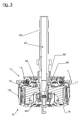
- the clutch 8 is equipped with a release mechanism 31.
- This disengagement mechanism has a disengaging member 32 that is axially movable along the longitudinal axis 20.
- the release element 32 can be disengaged in the direction of arrows 34.
- the first pressure plate 18 is disengaged in the direction of the arrows 34 via an expanding hook-shaped part 35 of the disengagement element 32 and thus lifted off the plate pack.
- the first pressure plate 18 is mounted via a support or thrust bearing 36.
- the support bearing 36 is designed according to a particular embodiment of the device according to the invention as a rolling bearing with an outer ring 37, an inner ring 38, and rolling elements 39 mounted therebetween.
- the roller bearing 36 absorbs the pressure force exerted by the disengagement element 32 during disengagement and disengages together with the disengagement element 32 and the first pressure plate 18.
- a driver brake 40 is arranged between the hook-shaped part 35 of the release element 32 and the support bearing 36.
- This driver brake as shown in FIGS. 5 and 6, designed as thrust washer 40 and has a central opening 41, and radially outwardly facing recesses 42 and radially inwardly facing recesses 43. While in the installed state, the release element 32 is received in the central opening 41, the radial recesses 42 and 43 are provided for guiding introduced lubricant. While in Fig. 5, the transmission input shaft facing side A of the driver brake 40 is shown in Fig. 6, the transmission input shaft facing away, side B of the driver brake 40 is shown.
- the driver brake 40 is made according to a preferred embodiment of the invention of a particularly wear-resistant material, for example of a heat-treated, preferably hardened or coated, metal, in particular spring steel.
- the thrust washer 40 has a first, in particular annular, friction surface 44, on which the thrust washer 40 is contacted by the fixed hook-shaped part 35 of the release element 32.
- the thrust washer has a second, in particular annular, friction surface 45 with respect to the first friction surface 44 on the opposite side of the thrust washer 44, to which the inner ring 38 of the rolling bearing 36 is contacted and a third, in particular circular, friction surface 46, at which the outer ring 37 of the rolling bearing 36 is touched during disengagement. Since the deceleration of the outer ring or the first support element of the support bearing is essential, can be dispensed according to a particular embodiment of the invention to the contact between the driver and the inner ring and the second support member of the support bearing.
- lubricant in particular oil
- the transmission input shaft 26 has at its end facing the clutch 8 an opening 48 which is suitably closed by a shutter 49.
- an opening 50 provided in the closure 49 and tuned, oil passes from the bore 47 of the transmission input shaft into the clutch 8.
- the opening 50 is arranged substantially centrally along the longitudinal axis 20. In this case, lubricant passes to the driver brake 40 and passes through the recesses 42 and 43 to the friction surfaces 44, 45 and 46.
- a motorcycle 51 is shown schematically.
- the motorcycle 51 has a front tire 52 and a rear tire 53.
- the illustrated motorcycle has only one front tire, the application of the clutch device according to the invention is not limited to this case and of course also in a multi-lane vehicle, especially a 3-wheeled motorcycle, or a so-called all-terrain vehicle (ATV, Quad) possible.
- the motorcycle has a frame 54 with a drive gear 55 attached thereto and a rear swingarm 56 attached to the frame.
- the drive unit 55 has a motor housing with a coupling device according to the invention accommodated therein.
- a motorcycle saddle 57 and a handlebar 58 with a clutch lever 59 attached thereto are further arranged.
Landscapes
- Engineering & Computer Science (AREA)
- General Engineering & Computer Science (AREA)
- Mechanical Engineering (AREA)
- Mechanical Operated Clutches (AREA)
Priority Applications (1)
| Application Number | Priority Date | Filing Date | Title |
|---|---|---|---|
| EP05024781A EP1785641A1 (fr) | 2005-11-14 | 2005-11-14 | Dispositif d'embrayage d'une unité de transmission d'un véhicule de loisir |
Applications Claiming Priority (1)
| Application Number | Priority Date | Filing Date | Title |
|---|---|---|---|
| EP05024781A EP1785641A1 (fr) | 2005-11-14 | 2005-11-14 | Dispositif d'embrayage d'une unité de transmission d'un véhicule de loisir |
Publications (1)
| Publication Number | Publication Date |
|---|---|
| EP1785641A1 true EP1785641A1 (fr) | 2007-05-16 |
Family
ID=35945264
Family Applications (1)
| Application Number | Title | Priority Date | Filing Date |
|---|---|---|---|
| EP05024781A Withdrawn EP1785641A1 (fr) | 2005-11-14 | 2005-11-14 | Dispositif d'embrayage d'une unité de transmission d'un véhicule de loisir |
Country Status (1)
| Country | Link |
|---|---|
| EP (1) | EP1785641A1 (fr) |
Citations (7)
| Publication number | Priority date | Publication date | Assignee | Title |
|---|---|---|---|---|
| JPS6049124A (ja) * | 1983-08-25 | 1985-03-18 | Yamaha Motor Co Ltd | 車両用クラッチ |
| FR2607884A3 (fr) | 1986-12-05 | 1988-06-10 | Adler Spa | Disque d'embrayage a friction en materiau de frottement, notamment pour vehicule a moteur |
| US4751989A (en) * | 1985-11-18 | 1988-06-21 | Honda Giken Kogyo Kabushiki Kaisha | Clutch with reduced dragging |
| DE3917404A1 (de) | 1988-07-06 | 1990-01-11 | Steyr Daimler Puch Ag | Einrichtung zur schmier- und kuehlmittelversorgung einer unter last schaltbaren kupplung eines kraftfahrzeuggetriebes |
| JPH07167157A (ja) * | 1993-12-17 | 1995-07-04 | Yamaha Motor Co Ltd | 多板摩擦クラッチ |
| JPH09177818A (ja) * | 1995-12-27 | 1997-07-11 | Honda Motor Co Ltd | 車両用クラッチ |
| EP1058018A2 (fr) | 1999-05-18 | 2000-12-06 | ADLER S.p.A. | Embrayage multi-disques avec dispositif hélicoidal pour le réglage de la compression axiale sur les disques |
-
2005
- 2005-11-14 EP EP05024781A patent/EP1785641A1/fr not_active Withdrawn
Patent Citations (7)
| Publication number | Priority date | Publication date | Assignee | Title |
|---|---|---|---|---|
| JPS6049124A (ja) * | 1983-08-25 | 1985-03-18 | Yamaha Motor Co Ltd | 車両用クラッチ |
| US4751989A (en) * | 1985-11-18 | 1988-06-21 | Honda Giken Kogyo Kabushiki Kaisha | Clutch with reduced dragging |
| FR2607884A3 (fr) | 1986-12-05 | 1988-06-10 | Adler Spa | Disque d'embrayage a friction en materiau de frottement, notamment pour vehicule a moteur |
| DE3917404A1 (de) | 1988-07-06 | 1990-01-11 | Steyr Daimler Puch Ag | Einrichtung zur schmier- und kuehlmittelversorgung einer unter last schaltbaren kupplung eines kraftfahrzeuggetriebes |
| JPH07167157A (ja) * | 1993-12-17 | 1995-07-04 | Yamaha Motor Co Ltd | 多板摩擦クラッチ |
| JPH09177818A (ja) * | 1995-12-27 | 1997-07-11 | Honda Motor Co Ltd | 車両用クラッチ |
| EP1058018A2 (fr) | 1999-05-18 | 2000-12-06 | ADLER S.p.A. | Embrayage multi-disques avec dispositif hélicoidal pour le réglage de la compression axiale sur les disques |
Non-Patent Citations (3)
| Title |
|---|
| PATENT ABSTRACTS OF JAPAN vol. 009, no. 179 (M - 399) 24 July 1985 (1985-07-24) * |
| PATENT ABSTRACTS OF JAPAN vol. 1995, no. 10 30 November 1995 (1995-11-30) * |
| PATENT ABSTRACTS OF JAPAN vol. 1997, no. 11 28 November 1997 (1997-11-28) * |
Similar Documents
| Publication | Publication Date | Title |
|---|---|---|
| DE102012108672B3 (de) | Nachstelleinrichtung einer Scheibenbremse, eine entsprechende Scheibenbremse und Verfahren zum Betreiben einer Verschleißnachstellvorrichtung einer Scheibenbremse | |
| EP2153080B1 (fr) | Dispositif d'embrayage double avec element de guidage de piston | |
| EP2145118B1 (fr) | Unité d'actionnement d'embrayage en fonction d'une différence couple/vitesse pour véhicules à moteur | |
| EP3102845B1 (fr) | Frein à disque de véhicule | |
| EP2318730B1 (fr) | Dispositif d'ajustement pour frein à disque | |
| EP1612386A1 (fr) | Roue motrice pour l'entraînement d'un appareil auxiliaire d'un vehicule | |
| DE19702198A1 (de) | Automatikgetriebe in Planetenbauweise | |
| EP0854304B1 (fr) | Embrayage à friction pour véhicules | |
| EP2895761B1 (fr) | Frein à disque pourvu d'un dispositif de rattrapage d'usure, procédé et dispositif permettant de faire fonctionner un dispositif de rattrapage d'usure d'un frein à disque | |
| WO2015120845A1 (fr) | Dispositif d'embrayage normalement embrayé | |
| DE102016010482A1 (de) | Drehmomentübertragunasvorrichtung für den Antriebsstrang eines Kraftfahrzeugs und Antriebsstrang mit einer solchen Drehmomentübertragungsvorrichtung | |
| DE102019124190B4 (de) | Trennkupplung mit drucktopfdurch- und hintergreifender Rückstellfeder mit Formschluss, Antriebsstrang und Verfahren zum Montieren einer Trennkupplung | |
| EP3314138B1 (fr) | Chaîne cinématique de véhicule automobile munie d'un embrayage à friction et embrayage à friction destiné à une chaîne cinématique de véhicule automobile | |
| EP2510260B1 (fr) | Boîte de vitesses d'un véhicule automobile avec un différentiel réglable | |
| DE102015116161B4 (de) | Scheibenbremse | |
| EP1785641A1 (fr) | Dispositif d'embrayage d'une unité de transmission d'un véhicule de loisir | |
| EP3724528B1 (fr) | Module hybride avec deuxieme groupe d'entrainement parallele a l'axe et deuxieme groupe motopropulseur | |
| DE3906337A1 (de) | Traegeranordnung in einem automatik-getriebe | |
| EP2368058B1 (fr) | Volant de démarreur à accouplement à friction | |
| DE1962963A1 (de) | Reibscheibenkupplung,insbesondere Trennkupplung fuer Wechselgetriebe von Kraftfahrzeugen | |
| DE102012200668A1 (de) | Radantrieb an einer Fahrzeugsachse | |
| DE10210177A1 (de) | Reibungskupplung mit separat ansteuerbarer Getriebebremse | |
| DE102019124192A1 (de) | Trennkupplung mit einstellbarer Rückstellfederauflage, Antriebsstrang und Verfahren zum Einstellen der Federkraft einer Rückstellfeder einer Trennkupplung | |
| DE102007045588A1 (de) | Drehmomentübertragungseinrichtung | |
| DE4318475B4 (de) | Scheibensatz für ein stufenloses Umschlingungsgetriebe |
Legal Events
| Date | Code | Title | Description |
|---|---|---|---|
| PUAI | Public reference made under article 153(3) epc to a published international application that has entered the european phase |
Free format text: ORIGINAL CODE: 0009012 |
|
| AK | Designated contracting states |
Kind code of ref document: A1 Designated state(s): AT BE BG CH CY CZ DE DK EE ES FI FR GB GR HU IE IS IT LI LT LU LV MC NL PL PT RO SE SI SK TR |
|
| AX | Request for extension of the european patent |
Extension state: AL BA HR MK YU |
|
| AKX | Designation fees paid | ||
| RTI1 | Title (correction) |
Free format text: CLUTCH DEVICE FOR THE DRIVE UNIT OF A LEISURE VEHICLE |
|
| REG | Reference to a national code |
Ref country code: DE Ref legal event code: 8566 |
|
| STAA | Information on the status of an ep patent application or granted ep patent |
Free format text: STATUS: THE APPLICATION IS DEEMED TO BE WITHDRAWN |
|
| 18D | Application deemed to be withdrawn |
Effective date: 20071117 |