EP1783716A1 - Procédé de fonctionnement d'un réseau domotique comprenant une interface de signalisation - Google Patents
Procédé de fonctionnement d'un réseau domotique comprenant une interface de signalisation Download PDFInfo
- Publication number
- EP1783716A1 EP1783716A1 EP06022884A EP06022884A EP1783716A1 EP 1783716 A1 EP1783716 A1 EP 1783716A1 EP 06022884 A EP06022884 A EP 06022884A EP 06022884 A EP06022884 A EP 06022884A EP 1783716 A1 EP1783716 A1 EP 1783716A1
- Authority
- EP
- European Patent Office
- Prior art keywords
- home automation
- command
- remote control
- order
- control
- Prior art date
- Legal status (The legal status is an assumption and is not a legal conclusion. Google has not performed a legal analysis and makes no representation as to the accuracy of the status listed.)
- Granted
Links
- 238000000034 method Methods 0.000 title claims abstract description 14
- 230000011664 signaling Effects 0.000 title claims description 11
- 230000008569 process Effects 0.000 title description 2
- 238000011017 operating method Methods 0.000 claims description 12
- 230000008859 change Effects 0.000 claims description 8
- 230000005540 biological transmission Effects 0.000 claims description 6
- 230000009471 action Effects 0.000 description 14
- 238000012545 processing Methods 0.000 description 4
- 238000010586 diagram Methods 0.000 description 3
- 238000012360 testing method Methods 0.000 description 3
- 230000007175 bidirectional communication Effects 0.000 description 2
- 238000012790 confirmation Methods 0.000 description 2
- 230000001419 dependent effect Effects 0.000 description 2
- 230000002159 abnormal effect Effects 0.000 description 1
- 230000008901 benefit Effects 0.000 description 1
- 230000006854 communication Effects 0.000 description 1
- 238000004891 communication Methods 0.000 description 1
- 230000003111 delayed effect Effects 0.000 description 1
- 230000007257 malfunction Effects 0.000 description 1
- 238000012986 modification Methods 0.000 description 1
- 230000004048 modification Effects 0.000 description 1
- 230000004044 response Effects 0.000 description 1
- 230000005236 sound signal Effects 0.000 description 1
- 230000000007 visual effect Effects 0.000 description 1
Images


Classifications
-
- G—PHYSICS
- G08—SIGNALLING
- G08C—TRANSMISSION SYSTEMS FOR MEASURED VALUES, CONTROL OR SIMILAR SIGNALS
- G08C17/00—Arrangements for transmitting signals characterised by the use of a wireless electrical link
- G08C17/02—Arrangements for transmitting signals characterised by the use of a wireless electrical link using a radio link
-
- G—PHYSICS
- G08—SIGNALLING
- G08C—TRANSMISSION SYSTEMS FOR MEASURED VALUES, CONTROL OR SIMILAR SIGNALS
- G08C2201/00—Transmission systems of control signals via wireless link
- G08C2201/50—Receiving or transmitting feedback, e.g. replies, status updates, acknowledgements, from the controlled devices
Definitions
- the invention relates to a method of operating a home automation network defined according to the preamble of claim 1.
- the invention also relates to a home automation network defined according to the preamble of claim 5.
- Such networks comprising at least one remote control communicating bidirectionally with at least one home automation equipment are for example used to control the movements of moving elements of a building such as for example blinds, shutters, doors or gates .
- the bidirectional communication makes it possible in particular to indicate to the users the state in which the mobile element controlled is located.
- a remote status indication function is for example known from an alarm system described in the patent. US 6,255,944 .
- Methods for indicating the state of moving elements have also been described in the applications US 2004/0239482 , US 2004/0239496 and DE 20 2005 011 907 .
- the status indication may be performed in response to a status request or as soon as an action is completed or to allow the evolution of a scenario comprising various actions to be followed.
- the bidirectional communication also allows the user to be informed that a command order can not be executed or that the execution of an action has been interrupted before reaching its end.
- Wireless remote controls for controlling home automation equipment often include a limited number of control buttons for issuing control commands. In some cases, these remote controls are still used to transmit different orders to different equipment.
- the transmitted control commands may correspond to state change orders: the control commands thus have meanings which depend on the states in which the domotic controlled equipment is located.
- pressing a button on a remote control can give rise to an action to open a shutter if it is closed and give rise to a closing action of the shutter if it is open.
- the document EP 1 014 326 an electronic key type remote control device for a vehicle, comprising a transceiver and means for displaying a feedback on the state of the controlled device.
- the transmitted control commands make it possible to modify the state of the controlled device, in particular they make it possible to lock or unlock a door.
- the order orders issued by the issuer of orders are not orders of type change of state.
- the order transmitter comprises two buttons: a first to issue a lock command when it is activated and a second to issue an unlock command when it is activated.
- the object of the invention is to provide a method of operating a network for solving the problem identified above and to improve the operating methods known from the prior art.
- the invention proposes a method of operation by means of which the user can obtain a maximum of information relating to the controlled equipment, especially in cases where very simple remotes with a minimum of control buttons are used.
- the method according to the invention is characterized by the characterizing part of claim 1.
- the home automation network according to the invention is defined by claim 5.
- the appended drawing shows, by way of example, an embodiment of a network according to the invention and embodiments of an operating method according to the invention.
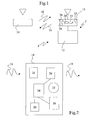
- Figure 1 is a diagram of a network according to the invention.
- Figure 2 is a diagram of a wireless remote control according to the invention.
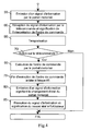
- Figure 3 is a flow chart of a first embodiment of the operating method according to the invention.
- FIG. 4 is a flow diagram of a second embodiment of the operating method according to the invention.
- FIG. 5 is a flow chart of a third embodiment of the operating method according to the invention.
- the invention can be applied to any type of home automation equipment network, it is described in its application to a motorized portal communicating bidirectionally with a remote control.
- the network 1, shown in FIG. 1, comprises a motorized gate device 2 and a wireless remote control 14, the motorized gate device and the wireless remote control communicating via electromagnetic signals 16 emitted by the motorized gate device 2 and electromagnetic signals 18 emitted by the remote control 14.
- the motorized gate device comprises an actuator 10 driving the gate 12 of the gate.
- the actuator 10 comprises an electric motor 32, transmission means 36 and 38 for receiving electromagnetic signals, a logic processing unit 34 and means 33 for controlling the power supply of the electric motor.
- the logic processing unit 34 comprises a microprocessor and software means including programs for implementing the different modes of execution of the operating method which are described below. It makes it possible to interpret the signals received by the signal receiving means and consequently to generate motor control signals which are transmitted to the motor power control means and to the interpretation information signals of the motor. control command which are emitted by the electromagnetic signal transmitting means towards the remote control.
- the signals emitted by the remote control comprise control commands of the motorized gate device.
- the signals emitted by the motorized gate device include portal status information. Examples of states of the motorized gate are for example: gate is completely open, the gate is completely closed, the gate is in an intermediate position, the gate opens, the gate closes, an obstacle has been detected, the movement of the gate has been reversed, the actuator is in a normal operating mode or the actuator is in an abnormal operating mode. Other states may be considered.
- information identifying the nature of the command issued in the direction of the motorized gate is sent to the attention of the user.
- the gate is, for example, controlled by the remote control in a four-cycle cycle: opening, stopping, closing, stopping ... by pressing the same button on the remote control and if pressing the button on the remote control is performed while the gate is stationary and the last gate move was an open move, gate closing command command information is sent to the user.
- the execution of this order may be delayed and / or require confirmation.
- the advantage of the invention is therefore to allow the user to be immediately informed of the interpretation of the order by the motorized gate. This information is all the more useful if the portal is not necessarily visible at the moment when the change of state command is issued, and / or when a second user could cause a maneuver of the portal without the first user know it, for example, making his order unwarranted.
- the wireless remote control 14 shown in FIG. 2 comprises a power supply 20, a logic processing unit 24, electromagnetic signal receiving means 28, transmission means for transmitting electromagnetic signals 26, a man-machine interface 22 and state signaling means 30.
- the power supply may consist of an accumulator battery or a means for converting chemical, solar or mechanical energy into electrical energy, this means being combined with a means for storing electrical energy.
- the human-machine interface may consist of a button or a keyboard comprising several buttons, a user action on one of these buttons causing the emission of an electromagnetic signal comprising a control command.
- the logic processing unit comprises a microprocessor and software means including programs for implementing the different modes of execution of the operating method which are described below. It makes it possible to transform action information on the man-machine interface into an instruction for transmitting a control signal 18 by the transmission means 26 towards the motorized gate. It also makes it possible to transform an information signal received by the reception means into information transmitted by the state signaling means 30 and which can be recognized by the user.
- the state signaling means may be of different types. They may consist of one or more visual indicators such as light-emitting diodes or lamps, for example a graphic, alphanumeric or animated screen or a sound indicator emitting for example one or more sound signals or a voice message. It can still be mechanical means to vibrate the remote control according to one or more frequencies and / or several intensities.
- visual indicators such as light-emitting diodes or lamps, for example a graphic, alphanumeric or animated screen or a sound indicator emitting for example one or more sound signals or a voice message. It can still be mechanical means to vibrate the remote control according to one or more frequencies and / or several intensities.
- the signaling can be ensured by the action of one of the means mentioned or by the action of a combination of the aforementioned means.
- FIG. 1 A first embodiment of the previously described network operating method is illustrated in FIG.
- a first step 40 the user acts on the remote control 14. This gives rise in a step 45 to the issuance of a control command 18 through the transmission means, this order being sent towards the portal motorized 2.
- the action on the remote control causing a change of state order (or "toggle"), it contains either explicitly a statement of change of state, or, which amounts to the same, information about the action exerted on the remote control.
- a step 50 the order is received and interpreted by the motorized gate.
- the motorized gate transmits towards the remote control 14, an information signal 16. This signal includes information determining the interpretation of the control command transmitted in step 45. It may also include a second information concerning the state in which the motorized gate is located and / or an acknowledgment of receipt.
- a step 60 the information signal is received by the remote control and the interpretation of the control command issued in step 45 is signaled to the user by the state signaling means 30.
- a gate opening command command can be signaled to the user by a light-emitting diode flash and a gate closure command command can be signaled to the user by three flashes of light emitting diode. This signaling is particularly useful when the gate is out of the user's field of vision, it allows him to verify that the action he has performed on the remote control has resulted in a command order consistent with his intention.
- step 65 the motorized gate 2 begins to execute the command command it received in step 50. This step can be carried out simultaneously with steps 55 and 60.
- a step 70 it tests whether the user acts on the remote control again.
- step 71 in which a new command order is issued towards the motorized gate.
- step 72 after receiving this new command command, the execution of the command command initiated in step 65 is interrupted.
- the motorized gate can return to the state that it initially occupied, that is to say before the transmission of the command order of step 45.
- an information signal is transmitted to the remote control to signal to the user that the execution of the command order has been interrupted or that the portal is returning to its initial state.
- a step 75 the execution of the command order initiated in step 65 is continued to completion.
- the portal transmits during a step 80 an information signal signifying its change of state. For example, at the end of the execution of an opening command command, it transmits an information signal meaning that it is stopped and that it is open.
- the remote control receives the information signal and indicates to the user the new state in which the motorized gate is located by using the state signaling means 30.
- the motorized gate sends to the remote control an information signal allowing it to inform the user that the order has not been executed correctly. It is obviously the same if the execution of the order can not be initiated.
- a second embodiment of the operating method according to the invention is described with reference to FIG. 4. It differs from the embodiment described above in that a timing step 95 is interposed between steps 60 and 70 and in that the command order execution step 65 is performed after the test step 70.
- This delay which can last for example for 2 seconds, enables the user to verify that the action he has taken on the remote control has given rise to a command order corresponding to his intention and to act if it is not possible. not the case.
- the test result of step 70 is negative and the process loops on one end of the procedure.
- the user reacts during the delay step by operating the remote control for example by pressing the same button that gave rise to the issuing of the command order, he confirms the command order and that This is done in the next step 65.
- a third embodiment of the method of operation according to the invention is described with reference to FIG. 5. It differs from the modes of execution previously described in that it comprises, during the step 65 of execution of FIG. control command, a step 115 for transmitting an information signal of the motorized portal to the remote control and a step 120 comprising a first substep of receiving the information signal for interpreting the command order and a second substep of significance to the user of the interpretation of the control command.
- steps 115 and 120 are for example iterated at regular intervals of time. Alternatively, only the second substep of meaning to the user is iterated as long as no information emitted by the motorized portal confirms the end of the execution of the command order (step 80).
- All communications may be followed by acknowledgment messages or be performed according to various protocols (eg Listen Before Talk).
- a "change of state” command command is understood to mean the same control command causing different actions at the level of a domotic equipment item controlled according to the state of this device.
Landscapes
- Engineering & Computer Science (AREA)
- Computer Networks & Wireless Communication (AREA)
- Physics & Mathematics (AREA)
- General Physics & Mathematics (AREA)
- Selective Calling Equipment (AREA)
Abstract
Description
- L'invention concerne un procédé de fonctionnement d'un réseau domotique défini selon le préambule de la revendication 1. L'invention concerne aussi un réseau domotique défini selon le préambule de la revendication 5.
- De tels réseaux comprenant au moins une télécommande communiquant de manière bidirectionnelle avec au moins un équipement domotique sont par exemple utilisés pour commander les mouvements d'éléments mobiles d'un bâtiment tels que par exemple des stores, des volets roulants, des portes ou des portails.
- La communication bidirectionnelle permet notamment d'indiquer aux utilisateurs l'état dans lequel se trouve l'élément mobile commandé. Une telle fonction d'indication d'état à distance est par exemple connue d'un système d'alarme décrit dans le brevet
US 6,255,944 . Des procédés d'indication de l'état d'éléments mobiles ont en outre été décrit dans les demandesUS 2004/0239482 ,US 2004/0239496 etDE 20 2005 011 907 . L'indication d'état peut être effectuée en réponse à une requête d'état ou dès qu'une action est terminée ou pour permettre de suivre l'évolution d'un scénario comprenant diverses actions. La communication bidirectionnelle permet en outre d'indiquer à l'utilisateur qu'un ordre de commande ne peut pas être exécuté ou que l'exécution d'une action a été interrompue avant d'atteindre son terme. - Les télécommandes sans fil pour commander les équipements domotiques comprennent souvent un nombre limité de boutons de commande permettant d'émettre des ordres de commande. Dans certains cas, ces télécommandes sont malgré tout utilisées pour émettre différents ordres de commande en direction de différents équipements. Les ordres de commande transmis peuvent correspondre à des ordres de changement d'état : les ordres de commande ont ainsi des significations qui dépendent des états dans lesquels se trouvent les équipements domotiques commandés. Ainsi, par exemple, un appui sur un bouton d'une télécommande peut donner lieu à une action d'ouverture d'un volet roulant si celui-ci se trouve fermé et donner lieu à une action de fermeture du volet roulant si celui-ci se trouve ouvert.
- Dans la mesure où il est possible qu'un utilisateur commande certains équipements domotiques sans que ceux-ci se trouvent dans son champ de vision, il apparaît intéressant que la télécommande utilisée fournisse un maximum d'informations à l'utilisateur.
- Outre les documents évoqués précédemment, on connaît du document
EP 1 014 326 un dispositif de commande à distance de type clé électronique pour véhicule, comprenant un émetteur-récepteur et des moyens d'affichage d'un retour d'information sur l'état du dispositif commandé. Les ordres de commande transmis permettent de modifier l'état du dispositif commandé, notamment ils permettent de verrouiller ou déverrouiller une porte. Cependant, les ordres de commande émis par l'émetteur d'ordres ne sont pas des ordres de type changement d'état. En effet, l'émetteur d'ordre comprend deux boutons : un premier pour émettre un ordre de verrouillage lorsqu'il est activé et un deuxième pour émettre un ordre de déverrouillage lorsqu'il est activé. - Le but de l'invention est de fournir un procédé de fonctionnement d'un réseau permettant de résoudre le problème identifié plus haut et d'améliorer les procédés de fonctionnement connus de l'art antérieur. En particulier, l'invention propose un procédé de fonctionnement grâce auquel l'utilisateur peut obtenir un maximum d'informations relatives aux équipements commandés, notamment dans les cas où des télécommandes très simples disposant d'un minimum de boutons de commande sont utilisées.
- Le procédé selon l'invention est caractérisé par la partie caractérisante de la revendication 1.
- Différents modes d'exécution du procédé de commande selon l'invention sont définis par les revendications dépendantes 2 à 4.
- Le réseau domotique selon l'invention est défini par la revendication 5.
- Différents modes de réalisation du procédé de commande selon l'invention sont définis par les revendications dépendantes 6 à 7.
- Le dessin annexé représente, à titre d'exemples, un mode de réalisation d'un réseau selon l'invention et des modes d'exécution d'un procédé de fonctionnement selon l'invention.
- La figure 1 est un schéma d'un réseau selon l'invention.
- La figure 2 est un schéma d'une télécommande sans fil selon l'invention.
- La figure 3 est un ordinogramme d'un premier mode d'exécution du procédé de fonctionnement selon l'invention.
- La figure 4 est un ordinogramme d'un deuxième mode d'exécution du procédé de fonctionnement selon l'invention.
- La figure 5 est un ordinogramme d'un troisième mode d'exécution du procédé de fonctionnement selon l'invention.
- Bien que l'invention puisse être appliquée à tout type de réseau d'équipement domotique, elle est décrite dans son application à un portail motorisé communiquant de manière bidirectionnelle avec une télécommande.
- Le réseau 1, représenté à la figure 1, comprend un dispositif de portail motorisé 2 et une télécommande sans fil 14, le dispositif de portail motorisé et la télécommande sans fil communiquant par le biais de signaux électromagnétiques 16 émis par le dispositif de portail motorisé 2 et de signaux électromagnétiques 18 émis par la télécommande 14.
- Le dispositif de portail motorisé comprend un actionneur 10 entraînant les ventaux 12 du portail. L'actionneur 10 comprend un moteur électrique 32, des moyens d'émission 36 et de réception 38 de signaux électromagnétiques, une unité logique de traitement 34 et des moyens 33 de pilotage de l'alimentation du moteur électrique. L'unité logique de traitement 34 comprend un microprocesseur et des moyens logiciels notamment des programmes pour mettre en oeuvre les différents modes d'exécution du procédé de fonctionnement qui sont décrits plus bas. Elle permet d'interpréter les signaux reçus par les moyens de réception de signaux et de générer en conséquence des signaux de pilotage du moteur qui sont transmis aux moyens de pilotage de l'alimentation du moteur et des signaux d'information d'interprétation d'ordre de commande qui sont émis par les moyens d'émission de signaux électromagnétiques en direction de la télécommande.
- Les signaux émis par la télécommande comprennent des ordres de commande du dispositif de portail motorisé. Les signaux émis par le dispositif de portail motorisé comprennent des informations d'état du portail. Des exemples d'états du portail motorisé sont par exemple : le portail est complètement ouvert, le portail est complètement fermé, le portail est dans une position intermédiaire, le portail s'ouvre, le portail se ferme, un obstacle a été détecté, le mouvement du portail a été inversé, l'actionneur se trouve dans un mode de fonctionnement normal ou l'actionneur se trouve dans un mode de fonctionnement anormal. D'autres états peuvent être envisagés.
- Selon l'invention, une information identifiant la nature de la commande émise en direction du portail motorisé est émise à l'attention de l'utilisateur. Ainsi, si le portail est, par exemple, commandé par la télécommande selon un cycle à quatre temps : ouverture, arrêt, fermeture, arrêt... par appui sur un même bouton de la télécommande et si un appui sur le bouton de la télécommande est effectué alors que le portail est à l'arrêt et que le dernier déplacement du portail était un déplacement d'ouverture, une information d'ordre de commande de fermeture du portail est émise en direction de l'utilisateur. L'exécution de cet ordre de commande peut être différée et/ou nécessiter une confirmation.
- L'intérêt de l'invention est donc de permettre à l'utilisateur d'être immédiatement informé de l'interprétation de l'ordre par le portail motorisé. Cette information est d'autant plus utile que le portail n'est pas nécessairement visible au moment où la commande de changement d'état est émise, et/ou qu'un deuxième utilisateur a pu provoquer une manoeuvre du portail sans que le premier utilisateur le sache, rendant par exemple sa commande injustifiée.
- La télécommande 14 sans fil représentée à la figure 2 comprend une alimentation 20, une unité logique de traitement 24, des moyens de réception de signaux électromagnétiques 28, des moyens d'émission de signaux électromagnétiques 26, une interface homme-machine 22 et des moyens 30 de signalisation d'état.
- L'alimentation peut consister en une batterie d'accumulateur ou en un moyen de conversion d'énergie chimique, solaire ou mécanique en énergie électrique, ce moyen étant combiné à un moyen de stockage d'énergie électrique.
- L'interface homme-machine peut consister en un bouton ou en un clavier comprenant plusieurs boutons, une action de l'utilisateur sur l'un de ces boutons provoquant l'émission d'un signal électromagnétique comprenant un ordre de commande.
- L'unité logique de traitement comprend un microprocesseur et des moyens logiciels notamment des programmes pour mettre en oeuvre les différents modes d'exécution du procédé de fonctionnement qui sont décrits plus bas. Elle permet de transformer une information d'action sur l'interface homme-machine en une instruction d'émission d'un signal 18 de commande par les moyens 26 d'émission en direction du portail motorisé. Elle permet en outre de transformer un signal d'information reçu par les moyens de réception en des informations émises par les moyens de signalisation d'état 30 et pouvant être reconnues par l'utilisateur.
- Les moyens de signalisation d'état peuvent être de différents types. Ils peuvent consister en un ou plusieurs indicateurs visuels tels que des diodes électroluminescentes ou des lampes, en un écran par exemple graphique, alphanumérique ou animé ou en un indicateur sonore émettant par exemple un ou plusieurs signaux sonores ou un message vocal. Il peut encore s'agir de moyens mécaniques pour faire vibrer la télécommande selon une ou plusieurs fréquences et/ou plusieurs intensités.
- La signalisation peut être assurée par l'action de l'un des moyens cités ou par l'action d'une combinaison de moyens cités.
- Un premier mode d'exécution du procédé de fonctionnement du réseau précédemment décrit est illustré par la figure 3.
- Dans une première étape 40, l'utilisateur agit sur la télécommande 14. Ceci donne lieu dans une étape 45 à l'émission d'un ordre de commande 18 par le biais des moyens d'émission, cet ordre étant émis en direction du portail motorisé 2. L'action sur la télécommande entraînant un ordre de changement d'état (ou « toggle »), il contient soit explicitement une instruction de changement d'état, soit, ce qui revient au même, une information concernant l'action exercée sur la télécommande.
- Dans une étape 50, l'ordre est reçu et interprété par le portail motorisé. Dans une étape 55, le portail motorisé émet en direction de la télécommande 14, un signal d'information 16. Ce signal comprend une information déterminant l'interprétation de l'ordre de commande transmis à l'étape 45. Il peut aussi comprendre une deuxième information concernant l'état dans lequel se trouve le portail motorisé et/ou un accusé de réception.
- Dans une étape 60, le signal d'information est reçu par la télécommande et l'interprétation de l'ordre de commande émis à l'étape 45 est signifié à l'utilisateur par les moyens de signalisation d'état 30. Par exemple, un ordre de commande d'ouverture de portail peut être signalé à l'utilisateur par un éclair de diode électroluminescente et un ordre de commande de fermeture de portail peut être signalé à l'utilisateur par trois éclairs de diode électroluminescente. Cette signalisation est particulièrement utile lorsque le portail est hors du champ de vision de l'utilisateur, elle lui permet de vérifier que l'action qu'il a effectuée sur la télécommande a entraîné un ordre de commande conforme à son intention.
- Dans une étape 65, le portail motorisé 2 commence à exécuter l'ordre de commande qu'il a reçu à l'étape 50. Cette étape peut se dérouler simultanément aux étapes 55 et 60.
- Dans une étape 70, on teste si l'utilisateur agit de nouveau sur la télécommande.
- Si tel est le cas, on passe à l'étape 71 dans laquelle un nouvel ordre de commande est émis en direction du portail motorisé. Dans une étape 72, après réception de ce nouvel ordre de commande, l'exécution de l'ordre de commande initiée à l'étape 65 est interrompue. Alternativement, le portail motorisé peut revenir à l'état qu'il occupait initialement c'est-à-dire avant l'émission de l'ordre de commande de l'étape 45. De préférence, un signal d'information est émis à la télécommande pour signaler à l'utilisateur que l'exécution de l'ordre de commande a été interrompue ou que le portail revient dans son état initial.
- Dans une étape 75, l'exécution de l'ordre de commande initié à l'étape 65 est poursuivie jusqu'à son terme. Une fois cet ordre de commande exécuté, le portail émet lors d'une étape 80 un signal d'information signifiant son changement d'état. Par exemple, à la fin de l'exécution d'un ordre de commande d'ouverture, il émet un signal d'information signifiant qu'il est à l'arrêt et qu'il est ouvert.
- Dans une étape 85, la télécommande reçoit le signal d'information et signifie à l'utilisateur le nouvel état dans lequel se trouve le portail motorisé en utilisant les moyens de signalisation d'état 30.
- Au cas où l'ordre de commande n'aurait pas pu être exécuté complètement (du fait par exemple d'un obstacle ayant bloqué le portail ou d'un dysfonctionnement), le portail motorisé envoie à la télécommande un signal d'information lui permettant de signifier à l'utilisateur que l'ordre de commande n'a pas été exécuté correctement. Il en est évidemment de même si l'exécution de l'ordre de commande ne peut être initiée.
- Un deuxième mode d'exécution du procédé de fonctionnement selon l'invention est décrit en référence à la figure 4. Il diffère du mode d'exécution précédemment décrit en ce qu'une étape de temporisation 95 est intercalée entre les étapes 60 et 70 et en ce que l'étape 65 d'exécution d'ordre de commande est réalisée après l'étape de test 70.
- Cette temporisation qui peut par exemple durer 2 secondes permet à l'utilisateur de vérifier que l'action qu'il a effectuée sur la télécommande a bien donné lieu à un ordre de commande conforme à son intention et d'agir si tel n'est pas le cas. Ainsi, par exemple, si l'utilisateur ne réagit pas pendant l'étape de temporisation, le résultat du test de l'étape 70 est négatif et le procédé boucle sur une fin de procédure. Inversement, si l'utilisateur réagit pendant l'étape de temporisation en actionnant la télécommande, par exemple en actionnant le même bouton que celui ayant donné lieu à l'émission de l'ordre de commande, il confirme l'ordre de commande et celui-ci est exécuté dès l'étape suivante 65.
- Alternativement, il peut être prévu que ce soit la passivité de l'utilisateur pendant l'étape de temporisation qui doit être interprétée comme une confirmation que l'ordre de commande transmis correspond effectivement à l'intention de l'utilisateur.
- Un troisième mode d'exécution du procédé de fonctionnement selon l'invention est décrit en référence à la figure 5. Il diffère des modes d'exécution précédemment décrits en ce qu'il comprend, lors de l'étape 65 d'exécution de l'ordre de commande, une étape 115 d'émission d'un signal d'information du portail motorisé à la télécommande et une étape 120 comprenant une première sous-étape de réception du signal d'information d'interprétation de l'ordre de commande et une deuxième sous-étape de signification à l'utilisateur de l'interprétation de l'ordre de commande. Ces étapes 115 et 120 sont par exemple itérées à intervalle de temps régulier. Alternativement, seule la deuxième sous-étape de signification à l'utilisateur est itérée tant qu'aucune information émise par le portail motorisé ne confirme la fin de l'exécution de l'ordre de commande (étape 80).
- Les modes d'exécution décrits sont susceptibles de nombreuses modifications. Toutes les communications peuvent être suivies de messages d'accusé de réception ou être effectuées selon des protocoles variés (par exemple Listen Before Talk).
- Comme déjà expliqué précédemment, dans la présente demande, on entend par ordre de commande « de type changement d'état », un même ordre de commande provoquant des actions différentes au niveau d'un équipement domotique commandé selon l'état de ce dispositif.
Claims (7)
- Procédé de fonctionnement d'un réseau domotique comprenant au moins une télécommande communiquant de manière bidirectionnelle avec au moins un équipement domotique, caractérisé en ce qu'il comprend, suite à l'émission d'un ordre de commande de la télécommande à l'équipement domotique, cet ordre étant de type changement d'état, une étape d'interprétation de l'ordre de commande par l'équipement domotique, une étape de transmission d'une information de l'équipement domotique à la télécommande et une étape de signalisation à l'utilisateur, par le biais de la télécommande, l'information et la signalisation étant relatives à l'interprétation de l'ordre émis.
- Procédé de fonctionnement selon la revendication 1, caractérisé en ce qu'une temporisation s'écoule entre la réception de l'ordre de commande et le début de l'exécution de l'ordre de commande.
- Procédé de fonctionnement selon la revendication 1, caractérisé en ce que l'exécution de l'ordre de commande débute dès la réception de l'ordre de commande.
- Procédé de fonctionnement selon l'une des revendications 1 à 3, caractérisé en ce que l'étape de signalisation à l'utilisateur de l'interprétation de l'ordre de commande émis est effectuée périodiquement pendant toute la durée de l'exécution de l'ordre de commande.
- Réseau domotique (1) comprenant au moins une télécommande (14) communiquant de manière bidirectionnelle avec au moins un équipement domotique (2), caractérisé en ce qu'il comprend des moyens matériels (22, 24, 26, 28, 34, 36, 38) et logiciels pour la mise en oeuvre du procédé de fonctionnement selon l'une des revendications 1 à 4.
- Réseau domotique selon la revendication 5, caractérisé en ce que l'équipement domotique est un portail motorisé.
- Réseau domotique selon la revendication 5, caractérisé en ce que l'équipement domotique est un dispositif de fermeture motorisé.
Priority Applications (1)
| Application Number | Priority Date | Filing Date | Title |
|---|---|---|---|
| PL06022884T PL1783716T3 (pl) | 2005-11-04 | 2006-11-03 | Sposób działania sieci automatyki domowej zawierającej interfejs sygnalizacyjny |
Applications Claiming Priority (1)
| Application Number | Priority Date | Filing Date | Title |
|---|---|---|---|
| FR0511265A FR2893170B1 (fr) | 2005-11-04 | 2005-11-04 | Procede de fonctionnement d'un reseau domotique comprenant une interface de signalisation. |
Publications (2)
| Publication Number | Publication Date |
|---|---|
| EP1783716A1 true EP1783716A1 (fr) | 2007-05-09 |
| EP1783716B1 EP1783716B1 (fr) | 2013-05-22 |
Family
ID=36580416
Family Applications (1)
| Application Number | Title | Priority Date | Filing Date |
|---|---|---|---|
| EP06022884.8A Not-in-force EP1783716B1 (fr) | 2005-11-04 | 2006-11-03 | Procédé de fonctionnement d'un réseau domotique comprenant une interface de signalisation |
Country Status (3)
| Country | Link |
|---|---|
| EP (1) | EP1783716B1 (fr) |
| FR (1) | FR2893170B1 (fr) |
| PL (1) | PL1783716T3 (fr) |
Cited By (1)
| Publication number | Priority date | Publication date | Assignee | Title |
|---|---|---|---|---|
| EP2492884A1 (fr) | 2011-02-28 | 2012-08-29 | Somfy SAS | Dispositif de commande comprenant une interface capable de proposer le prochain ordre de commande à transmettre à un équipement domotique |
Citations (1)
| Publication number | Priority date | Publication date | Assignee | Title |
|---|---|---|---|---|
| EP1014326A1 (fr) * | 1998-12-22 | 2000-06-28 | Robert Bosch Gmbh | Dispositif de commande à distance pour commander l'actionneur des portes ou des véhicules |
-
2005
- 2005-11-04 FR FR0511265A patent/FR2893170B1/fr not_active Expired - Fee Related
-
2006
- 2006-11-03 EP EP06022884.8A patent/EP1783716B1/fr not_active Not-in-force
- 2006-11-03 PL PL06022884T patent/PL1783716T3/pl unknown
Patent Citations (1)
| Publication number | Priority date | Publication date | Assignee | Title |
|---|---|---|---|---|
| EP1014326A1 (fr) * | 1998-12-22 | 2000-06-28 | Robert Bosch Gmbh | Dispositif de commande à distance pour commander l'actionneur des portes ou des véhicules |
Cited By (2)
| Publication number | Priority date | Publication date | Assignee | Title |
|---|---|---|---|---|
| EP2492884A1 (fr) | 2011-02-28 | 2012-08-29 | Somfy SAS | Dispositif de commande comprenant une interface capable de proposer le prochain ordre de commande à transmettre à un équipement domotique |
| US8972030B2 (en) | 2011-02-28 | 2015-03-03 | Somfy Sas | Control device comprising an interface capable of proposing the next control command to be transmitted to a home-automation appliance |
Also Published As
| Publication number | Publication date |
|---|---|
| EP1783716B1 (fr) | 2013-05-22 |
| PL1783716T3 (pl) | 2013-11-29 |
| FR2893170A1 (fr) | 2007-05-11 |
| FR2893170B1 (fr) | 2008-01-18 |
Similar Documents
| Publication | Publication Date | Title |
|---|---|---|
| EP2259242B1 (fr) | Procédé de communication par relais entre une télécommande nomade et des équipements domotiques. | |
| EP1476859B1 (fr) | Procédé d'appariement d'objets bidirectionnels | |
| EP2009527B1 (fr) | Procédé de configuration d'un system d'entraînement d'un écran de fermeture, de protection solaire ou de projection | |
| FR2855643A1 (fr) | Procede et appareil a signaux d'etats pour un actionneur de barriere mobile et commande a distance sans fil correspondante | |
| EP1476860B1 (fr) | Procédé de définition d'un groupe parmi des objets bidirectionnels | |
| EP1469439B3 (fr) | Procédé de fonctionnement d'un émetteur d'ordres | |
| EP2492884A1 (fr) | Dispositif de commande comprenant une interface capable de proposer le prochain ordre de commande à transmettre à un équipement domotique | |
| EP1783716B1 (fr) | Procédé de fonctionnement d'un réseau domotique comprenant une interface de signalisation | |
| FR3000984A3 (fr) | Portail d'un dispositif d'entrainement de fermeture d'un batiment ou d'une cloture et son application | |
| EP1561192B1 (fr) | Procede de securisation du mode d enregistrement d un d ispositif domotique | |
| WO2012011073A1 (fr) | Chaîne de télécommande comprenant un téléphone mobile avec une fonction de télécommande et un émulateur de télécommande | |
| EP2387016B1 (fr) | Procédé de localisation d'une unité de commande d'un actionneur de manoeuvre d'un element de couverture de fenêtre | |
| EP2017804A1 (fr) | Procédé de fonctionnement d'un émetteur d'ordres dans une installation domotique et émetteur d'ordres pour sa mise en oeuvre | |
| EP2893693B1 (fr) | Unité nomade de commande des conditions de confort et/ou de sécurité dans un bâtiment | |
| FR3139848A1 (fr) | Système de contrôle d’accès | |
| EP1950722B1 (fr) | Procédé de configuration d'un transmetteur d'ordres dans un système domotique | |
| EP3543804A1 (fr) | Procédé de pilotage d'un dispositif domotique | |
| EP1870867B1 (fr) | Procédé de communication dans un système domotique et système domotique pour sa mise en oeuvre | |
| EP2608510B1 (fr) | Dispositif et méthode de commande domotique par téléphone | |
| EP2810266B1 (fr) | Procédé et dispositif de communication pour la commande à distance d'un actionneur pour un équipement mobile du bâtiment | |
| EP3173565B1 (fr) | Procédé de commande en fonctionnement d'une installation domotique de fermeture | |
| EP1523739A1 (fr) | Procede de transmission d'ordres entre un emetteur et un recepteur |
Legal Events
| Date | Code | Title | Description |
|---|---|---|---|
| PUAI | Public reference made under article 153(3) epc to a published international application that has entered the european phase |
Free format text: ORIGINAL CODE: 0009012 |
|
| 17P | Request for examination filed |
Effective date: 20070329 |
|
| AK | Designated contracting states |
Kind code of ref document: A1 Designated state(s): AT BE BG CH CY CZ DE DK EE ES FI FR GB GR HU IE IS IT LI LT LU LV MC NL PL PT RO SE SI SK TR |
|
| AX | Request for extension of the european patent |
Extension state: AL BA HR MK YU |
|
| 17Q | First examination report despatched |
Effective date: 20070720 |
|
| AKX | Designation fees paid |
Designated state(s): AT BE BG CH CY CZ DE DK EE ES FI FR GB GR HU IE IS IT LI LT LU LV MC NL PL PT RO SE SI SK TR |
|
| REG | Reference to a national code |
Ref country code: DE Ref legal event code: R079 Ref document number: 602006036369 Country of ref document: DE Free format text: PREVIOUS MAIN CLASS: G08C0025020000 Ipc: G08C0017020000 |
|
| GRAP | Despatch of communication of intention to grant a patent |
Free format text: ORIGINAL CODE: EPIDOSNIGR1 |
|
| RIC1 | Information provided on ipc code assigned before grant |
Ipc: G08C 17/02 20060101AFI20121112BHEP |
|
| GRAS | Grant fee paid |
Free format text: ORIGINAL CODE: EPIDOSNIGR3 |
|
| GRAA | (expected) grant |
Free format text: ORIGINAL CODE: 0009210 |
|
| AK | Designated contracting states |
Kind code of ref document: B1 Designated state(s): AT BE BG CH CY CZ DE DK EE ES FI FR GB GR HU IE IS IT LI LT LU LV MC NL PL PT RO SE SI SK TR |
|
| REG | Reference to a national code |
Ref country code: GB Ref legal event code: FG4D Free format text: NOT ENGLISH |
|
| REG | Reference to a national code |
Ref country code: CH Ref legal event code: EP |
|
| REG | Reference to a national code |
Ref country code: AT Ref legal event code: REF Ref document number: 613583 Country of ref document: AT Kind code of ref document: T Effective date: 20130615 |
|
| REG | Reference to a national code |
Ref country code: IE Ref legal event code: FG4D Free format text: LANGUAGE OF EP DOCUMENT: FRENCH |
|
| REG | Reference to a national code |
Ref country code: DE Ref legal event code: R096 Ref document number: 602006036369 Country of ref document: DE Effective date: 20130718 |
|
| REG | Reference to a national code |
Ref country code: AT Ref legal event code: MK05 Ref document number: 613583 Country of ref document: AT Kind code of ref document: T Effective date: 20130522 |
|
| REG | Reference to a national code |
Ref country code: LT Ref legal event code: MG4D |
|
| PG25 | Lapsed in a contracting state [announced via postgrant information from national office to epo] |
Ref country code: LT Free format text: LAPSE BECAUSE OF FAILURE TO SUBMIT A TRANSLATION OF THE DESCRIPTION OR TO PAY THE FEE WITHIN THE PRESCRIBED TIME-LIMIT Effective date: 20130522 Ref country code: AT Free format text: LAPSE BECAUSE OF FAILURE TO SUBMIT A TRANSLATION OF THE DESCRIPTION OR TO PAY THE FEE WITHIN THE PRESCRIBED TIME-LIMIT Effective date: 20130522 Ref country code: PT Free format text: LAPSE BECAUSE OF FAILURE TO SUBMIT A TRANSLATION OF THE DESCRIPTION OR TO PAY THE FEE WITHIN THE PRESCRIBED TIME-LIMIT Effective date: 20130923 Ref country code: SE Free format text: LAPSE BECAUSE OF FAILURE TO SUBMIT A TRANSLATION OF THE DESCRIPTION OR TO PAY THE FEE WITHIN THE PRESCRIBED TIME-LIMIT Effective date: 20130522 Ref country code: GR Free format text: LAPSE BECAUSE OF FAILURE TO SUBMIT A TRANSLATION OF THE DESCRIPTION OR TO PAY THE FEE WITHIN THE PRESCRIBED TIME-LIMIT Effective date: 20130823 Ref country code: IS Free format text: LAPSE BECAUSE OF FAILURE TO SUBMIT A TRANSLATION OF THE DESCRIPTION OR TO PAY THE FEE WITHIN THE PRESCRIBED TIME-LIMIT Effective date: 20130922 Ref country code: ES Free format text: LAPSE BECAUSE OF FAILURE TO SUBMIT A TRANSLATION OF THE DESCRIPTION OR TO PAY THE FEE WITHIN THE PRESCRIBED TIME-LIMIT Effective date: 20130902 Ref country code: SI Free format text: LAPSE BECAUSE OF FAILURE TO SUBMIT A TRANSLATION OF THE DESCRIPTION OR TO PAY THE FEE WITHIN THE PRESCRIBED TIME-LIMIT Effective date: 20130522 Ref country code: FI Free format text: LAPSE BECAUSE OF FAILURE TO SUBMIT A TRANSLATION OF THE DESCRIPTION OR TO PAY THE FEE WITHIN THE PRESCRIBED TIME-LIMIT Effective date: 20130522 |
|
| REG | Reference to a national code |
Ref country code: NL Ref legal event code: VDEP Effective date: 20130522 |
|
| PG25 | Lapsed in a contracting state [announced via postgrant information from national office to epo] |
Ref country code: BG Free format text: LAPSE BECAUSE OF FAILURE TO SUBMIT A TRANSLATION OF THE DESCRIPTION OR TO PAY THE FEE WITHIN THE PRESCRIBED TIME-LIMIT Effective date: 20130822 |
|
| REG | Reference to a national code |
Ref country code: PL Ref legal event code: T3 |
|
| PG25 | Lapsed in a contracting state [announced via postgrant information from national office to epo] |
Ref country code: LV Free format text: LAPSE BECAUSE OF FAILURE TO SUBMIT A TRANSLATION OF THE DESCRIPTION OR TO PAY THE FEE WITHIN THE PRESCRIBED TIME-LIMIT Effective date: 20130522 |
|
| PG25 | Lapsed in a contracting state [announced via postgrant information from national office to epo] |
Ref country code: DK Free format text: LAPSE BECAUSE OF FAILURE TO SUBMIT A TRANSLATION OF THE DESCRIPTION OR TO PAY THE FEE WITHIN THE PRESCRIBED TIME-LIMIT Effective date: 20130522 Ref country code: EE Free format text: LAPSE BECAUSE OF FAILURE TO SUBMIT A TRANSLATION OF THE DESCRIPTION OR TO PAY THE FEE WITHIN THE PRESCRIBED TIME-LIMIT Effective date: 20130522 Ref country code: SK Free format text: LAPSE BECAUSE OF FAILURE TO SUBMIT A TRANSLATION OF THE DESCRIPTION OR TO PAY THE FEE WITHIN THE PRESCRIBED TIME-LIMIT Effective date: 20130522 Ref country code: CZ Free format text: LAPSE BECAUSE OF FAILURE TO SUBMIT A TRANSLATION OF THE DESCRIPTION OR TO PAY THE FEE WITHIN THE PRESCRIBED TIME-LIMIT Effective date: 20130522 |
|
| PG25 | Lapsed in a contracting state [announced via postgrant information from national office to epo] |
Ref country code: NL Free format text: LAPSE BECAUSE OF FAILURE TO SUBMIT A TRANSLATION OF THE DESCRIPTION OR TO PAY THE FEE WITHIN THE PRESCRIBED TIME-LIMIT Effective date: 20130522 Ref country code: RO Free format text: LAPSE BECAUSE OF FAILURE TO SUBMIT A TRANSLATION OF THE DESCRIPTION OR TO PAY THE FEE WITHIN THE PRESCRIBED TIME-LIMIT Effective date: 20130522 |
|
| PLBE | No opposition filed within time limit |
Free format text: ORIGINAL CODE: 0009261 |
|
| STAA | Information on the status of an ep patent application or granted ep patent |
Free format text: STATUS: NO OPPOSITION FILED WITHIN TIME LIMIT |
|
| 26N | No opposition filed |
Effective date: 20140225 |
|
| BERE | Be: lapsed |
Owner name: SOMFY SAS Effective date: 20131130 |
|
| REG | Reference to a national code |
Ref country code: DE Ref legal event code: R097 Ref document number: 602006036369 Country of ref document: DE Effective date: 20140225 |
|
| REG | Reference to a national code |
Ref country code: CH Ref legal event code: PL |
|
| PG25 | Lapsed in a contracting state [announced via postgrant information from national office to epo] |
Ref country code: LI Free format text: LAPSE BECAUSE OF NON-PAYMENT OF DUE FEES Effective date: 20131130 Ref country code: CH Free format text: LAPSE BECAUSE OF NON-PAYMENT OF DUE FEES Effective date: 20131130 Ref country code: MC Free format text: LAPSE BECAUSE OF FAILURE TO SUBMIT A TRANSLATION OF THE DESCRIPTION OR TO PAY THE FEE WITHIN THE PRESCRIBED TIME-LIMIT Effective date: 20130522 |
|
| REG | Reference to a national code |
Ref country code: IE Ref legal event code: MM4A |
|
| PG25 | Lapsed in a contracting state [announced via postgrant information from national office to epo] |
Ref country code: BE Free format text: LAPSE BECAUSE OF NON-PAYMENT OF DUE FEES Effective date: 20131130 |
|
| PG25 | Lapsed in a contracting state [announced via postgrant information from national office to epo] |
Ref country code: IE Free format text: LAPSE BECAUSE OF NON-PAYMENT OF DUE FEES Effective date: 20131103 |
|
| PG25 | Lapsed in a contracting state [announced via postgrant information from national office to epo] |
Ref country code: TR Free format text: LAPSE BECAUSE OF FAILURE TO SUBMIT A TRANSLATION OF THE DESCRIPTION OR TO PAY THE FEE WITHIN THE PRESCRIBED TIME-LIMIT Effective date: 20130522 Ref country code: CY Free format text: LAPSE BECAUSE OF FAILURE TO SUBMIT A TRANSLATION OF THE DESCRIPTION OR TO PAY THE FEE WITHIN THE PRESCRIBED TIME-LIMIT Effective date: 20130522 |
|
| PG25 | Lapsed in a contracting state [announced via postgrant information from national office to epo] |
Ref country code: LU Free format text: LAPSE BECAUSE OF NON-PAYMENT OF DUE FEES Effective date: 20131103 Ref country code: HU Free format text: LAPSE BECAUSE OF FAILURE TO SUBMIT A TRANSLATION OF THE DESCRIPTION OR TO PAY THE FEE WITHIN THE PRESCRIBED TIME-LIMIT; INVALID AB INITIO Effective date: 20061103 |
|
| REG | Reference to a national code |
Ref country code: FR Ref legal event code: PLFP Year of fee payment: 10 |
|
| REG | Reference to a national code |
Ref country code: DE Ref legal event code: R082 Ref document number: 602006036369 Country of ref document: DE |
|
| REG | Reference to a national code |
Ref country code: FR Ref legal event code: PLFP Year of fee payment: 11 |
|
| REG | Reference to a national code |
Ref country code: FR Ref legal event code: PLFP Year of fee payment: 12 |
|
| PGFP | Annual fee paid to national office [announced via postgrant information from national office to epo] |
Ref country code: GB Payment date: 20201026 Year of fee payment: 15 Ref country code: IT Payment date: 20201112 Year of fee payment: 15 |
|
| PGFP | Annual fee paid to national office [announced via postgrant information from national office to epo] |
Ref country code: PL Payment date: 20201019 Year of fee payment: 15 |
|
| REG | Reference to a national code |
Ref country code: DE Ref legal event code: R081 Ref document number: 602006036369 Country of ref document: DE Owner name: SOMFY ACTIVITES SA, FR Free format text: FORMER OWNER: SOMFY SAS, CLUSES, FR |
|
| GBPC | Gb: european patent ceased through non-payment of renewal fee |
Effective date: 20211103 |
|
| PG25 | Lapsed in a contracting state [announced via postgrant information from national office to epo] |
Ref country code: GB Free format text: LAPSE BECAUSE OF NON-PAYMENT OF DUE FEES Effective date: 20211103 |
|
| PG25 | Lapsed in a contracting state [announced via postgrant information from national office to epo] |
Ref country code: IT Free format text: LAPSE BECAUSE OF NON-PAYMENT OF DUE FEES Effective date: 20211103 |
|
| PGFP | Annual fee paid to national office [announced via postgrant information from national office to epo] |
Ref country code: FR Payment date: 20221129 Year of fee payment: 17 Ref country code: DE Payment date: 20221027 Year of fee payment: 17 |
|
| PG25 | Lapsed in a contracting state [announced via postgrant information from national office to epo] |
Ref country code: PL Free format text: LAPSE BECAUSE OF NON-PAYMENT OF DUE FEES Effective date: 20211103 |
|
| REG | Reference to a national code |
Ref country code: DE Ref legal event code: R119 Ref document number: 602006036369 Country of ref document: DE |
|
| PG25 | Lapsed in a contracting state [announced via postgrant information from national office to epo] |
Ref country code: DE Free format text: LAPSE BECAUSE OF NON-PAYMENT OF DUE FEES Effective date: 20240601 |
|
| PG25 | Lapsed in a contracting state [announced via postgrant information from national office to epo] |
Ref country code: FR Free format text: LAPSE BECAUSE OF NON-PAYMENT OF DUE FEES Effective date: 20231130 |
|
| PG25 | Lapsed in a contracting state [announced via postgrant information from national office to epo] |
Ref country code: FR Free format text: LAPSE BECAUSE OF NON-PAYMENT OF DUE FEES Effective date: 20231130 Ref country code: DE Free format text: LAPSE BECAUSE OF NON-PAYMENT OF DUE FEES Effective date: 20240601 |