EP1783043A2 - Dispositif de commande de changement de vitesses pour bicyclette - Google Patents
Dispositif de commande de changement de vitesses pour bicyclette Download PDFInfo
- Publication number
- EP1783043A2 EP1783043A2 EP06022722A EP06022722A EP1783043A2 EP 1783043 A2 EP1783043 A2 EP 1783043A2 EP 06022722 A EP06022722 A EP 06022722A EP 06022722 A EP06022722 A EP 06022722A EP 1783043 A2 EP1783043 A2 EP 1783043A2
- Authority
- EP
- European Patent Office
- Prior art keywords
- shift
- positioning
- teeth
- positioning ratchet
- operating member
- Prior art date
- Legal status (The legal status is an assumption and is not a legal conclusion. Google has not performed a legal analysis and makes no representation as to the accuracy of the status listed.)
- Granted
Links
- 230000007246 mechanism Effects 0.000 title claims abstract description 46
- 238000004804 winding Methods 0.000 claims abstract description 92
- 230000004044 response Effects 0.000 claims description 4
- 230000007423 decrease Effects 0.000 claims description 3
- 230000002093 peripheral effect Effects 0.000 description 6
- 230000009471 action Effects 0.000 description 2
- 230000003213 activating effect Effects 0.000 description 2
- 230000008901 benefit Effects 0.000 description 2
- 238000010276 construction Methods 0.000 description 2
- 230000036961 partial effect Effects 0.000 description 2
- 230000005540 biological transmission Effects 0.000 description 1
- 230000002860 competitive effect Effects 0.000 description 1
- 230000008878 coupling Effects 0.000 description 1
- 238000010168 coupling process Methods 0.000 description 1
- 238000005859 coupling reaction Methods 0.000 description 1
- 230000009977 dual effect Effects 0.000 description 1
- 230000002452 interceptive effect Effects 0.000 description 1
- 238000004519 manufacturing process Methods 0.000 description 1
- 230000004048 modification Effects 0.000 description 1
- 238000012986 modification Methods 0.000 description 1
Images


Classifications
-
- B—PERFORMING OPERATIONS; TRANSPORTING
- B62—LAND VEHICLES FOR TRAVELLING OTHERWISE THAN ON RAILS
- B62M—RIDER PROPULSION OF WHEELED VEHICLES OR SLEDGES; POWERED PROPULSION OF SLEDGES OR SINGLE-TRACK CYCLES; TRANSMISSIONS SPECIALLY ADAPTED FOR SUCH VEHICLES
- B62M25/00—Actuators for gearing speed-change mechanisms specially adapted for cycles
- B62M25/02—Actuators for gearing speed-change mechanisms specially adapted for cycles with mechanical transmitting systems, e.g. cables, levers
- B62M25/04—Actuators for gearing speed-change mechanisms specially adapted for cycles with mechanical transmitting systems, e.g. cables, levers hand actuated
-
- Y—GENERAL TAGGING OF NEW TECHNOLOGICAL DEVELOPMENTS; GENERAL TAGGING OF CROSS-SECTIONAL TECHNOLOGIES SPANNING OVER SEVERAL SECTIONS OF THE IPC; TECHNICAL SUBJECTS COVERED BY FORMER USPC CROSS-REFERENCE ART COLLECTIONS [XRACs] AND DIGESTS
- Y10—TECHNICAL SUBJECTS COVERED BY FORMER USPC
- Y10T—TECHNICAL SUBJECTS COVERED BY FORMER US CLASSIFICATION
- Y10T74/00—Machine element or mechanism
- Y10T74/20—Control lever and linkage systems
- Y10T74/20207—Multiple controlling elements for single controlled element
- Y10T74/20256—Steering and controls assemblies
- Y10T74/20268—Reciprocating control elements
- Y10T74/2028—Handle bar type
- Y10T74/20287—Flexible control element
-
- Y—GENERAL TAGGING OF NEW TECHNOLOGICAL DEVELOPMENTS; GENERAL TAGGING OF CROSS-SECTIONAL TECHNOLOGIES SPANNING OVER SEVERAL SECTIONS OF THE IPC; TECHNICAL SUBJECTS COVERED BY FORMER USPC CROSS-REFERENCE ART COLLECTIONS [XRACs] AND DIGESTS
- Y10—TECHNICAL SUBJECTS COVERED BY FORMER USPC
- Y10T—TECHNICAL SUBJECTS COVERED BY FORMER US CLASSIFICATION
- Y10T74/00—Machine element or mechanism
- Y10T74/20—Control lever and linkage systems
- Y10T74/20396—Hand operated
- Y10T74/20402—Flexible transmitter [e.g., Bowden cable]
- Y10T74/2042—Flexible transmitter [e.g., Bowden cable] and hand operator
- Y10T74/20438—Single rotatable lever [e.g., for bicycle brake or derailleur]
Definitions
- This invention generally relates to a bicycle shift control device or mechanism. More specifically, the present invention relates to a bicycle control device or mechanism that performs a shift release operation one shift at a time.
- Bicycling is becoming an increasingly more popular form of recreation as well as a means of transportation. Moreover, bicycling has become a very popular competitive sport for both amateurs and professionals. Whether the bicycle is used for recreation, transportation or competition, the bicycle industry is constantly improving the various components of the bicycle. In particular, control devices for shifting have been extensively redesigned in recent years.
- some cable operated shifting devices have a single shift lever to operate a cable winding mechanism for both winding and releasing the cable.
- Other cable operated shifting devices have a pair of shift levers with a cable winding mechanism that rotates via a ratchet mechanism.
- operation of one of the shift lever causes the cable winder to rotate via the ratchet mechanism in one direction by one gear at a time.
- the cable is wound around the cable winder, and a shift is made by the shift mechanism from one gear to the next gear.
- Operation of the other shift lever causes the ratchet mechanism to be released and the cable winder to rotate in the other direction by one gear at a time.
- the cable that was wound on the cable winder is played out, and a shift is made in the opposite direction by the shift mechanism.
- Some of these cable operated shifting devices allow for multiple gear shifts to occur in a single operation of a shift lever. While multiple shifting in a single operation has certain benefits, it also can have some drawbacks. In particular, with certain shifting devices with a multiple shifting operation, sometimes the shifter is difficult to control so as to perform a single shift. In other words, the rider will sometimes accidentally move the shift lever too far such that two gear shifts occur when only one is desired. This accidental multiple shifting operation is particularly problematic during a shifting operation in which the cable is released.
- One object of the present invention is to provide a bicycle shift control device or mechanism that limits the shifting operation to a single shift position during a shifting operation in which the cable is released.
- Another object of the present invention is to provide a bicycle control device or mechanism for shifting a bicycle transmission that is relatively simple and inexpensive to manufacture and assemble.
- a bicycle shift control mechanism that has an operating member, a wire take up member, a positioning ratchet and a position maintaining pawl.
- the operating member is movable between a rest position and a shift releasing position.
- the wire take up member is configured and arranged to rotate about a rotational axis in response to movement of the operating member.
- the positioning ratchet is configured and arranged to rotate with the wire take up member.
- the positioning ratchet includes a plurality of positioning teeth.
- the positioning ratchet is mounted about a main pivot axis with the positioning teeth of the positioning ratchet being non-concentrically arranged with respect to the main pivot axis so that the positioning teeth form a stair shaped arrangement.
- the position maintaining pawl is configured and arranged to selectively hold the positioning ratchet in one of a plurality of predetermined shift positions by engaging one of the positioning teeth of the positioning ratchet when the position maintaining pawl is in a position maintaining position.
- the position maintaining pawl is further configured and arranged to move from the position maintaining position to a position releasing position to release the positioning ratchet upon movement of the operating member from the rest position to the shift releasing position with the position maintaining pawl engaging the positioning ratchet to restrict movement of the position maintaining pawl.
- Figure 1 is a side elevational view of a bicycle equipped with a pair of control devices (only one shown) in accordance with one embodiment of the present invention
- FIG. 2 is a top plan view of the bicycle handlebar with the bicycle control devices coupled thereto in accordance with the present invention
- FIG. 3 is an enlarged bottom perspective view of the front bicycle control device in accordance with the present invention.
- Figure 4 is a bottom plan view of the front bicycle control device with the operating member (shift lever) in the rest position;
- Figure 5 is a partial cross sectional view of the front bicycle control device as viewed along section line 5-5 of Figure 4;
- Figure 6 is a bottom plan view of the front bicycle control device with the operating member (shift lever) moved to perform a cable pulling (winding) operation;
- Figure 7 is a bottom plan view of the front bicycle control device with the operating member (shift lever) moved to perform a cable releasing (unwinding) operation;
- Figure 8 is a bottom plan view of the front bicycle control device with the operating member (shift lever) in the rest position with certain parts removed for purposes of illustration;
- Figure 9 is a bottom plan view of the rear bicycle control device with the operating member (shift lever) in the rest position;
- Figure 10 is a bottom plan view of the rear bicycle control device with the operating member (shift lever) moved to perform a cable winding operation;
- Figure 11 is a bottom plan view of the rear bicycle control device with the operating member (shift lever) in the rest position with certain parts removed for purposes of illustration;
- Figure 12 is an exploded bottom side perspective view of the front bicycle control device in accordance with the present invention.
- Figure 13 is an exploded side elevational view of the front bicycle control device in accordance with the present invention.
- Figure 14 is an exploded bottom plan view of selected parts of the front bicycle control device in accordance with the present invention.
- Figure 15 is an exploded bottom side perspective view of the rear bicycle control device in accordance with the present invention.
- Figure 16 is an exploded side elevational view of the rear bicycle control device in accordance with the present invention.
- Figure 17 is an exploded bottom plan view of selected parts of the rear bicycle control device in accordance with the present invention.
- Figure 18 is a simplified bottom plan view of selected parts of the shift position control mechanism of the rear bicycle control device (certain parts removed for purposes of illustration) showing the shift position control mechanism in the rest position;
- Figure 19 is a simplified bottom plan view of selected parts of the shift position control mechanism for the rear bicycle control device (certain parts removed for purposes of illustration) showing the shift position control mechanism being moved to a wire winding position prior to movement of the position maintaining pawl back to a shift position maintaining position;
- Figure 20 is a simplified bottom plan view of selected parts of the shift position control mechanism for the rear bicycle control device (certain parts removed for purposes of illustration) showing the position maintaining pawl being moved to a shift position maintaining position and the winding pawl moving back to the initial rest position due to the release of the operating member (shift lever);
- Figure 21 is a simplified bottom plan view, similar to Figure 19, of selected parts of the shift position control mechanism for the rear bicycle control device (certain parts removed for purposes of illustration) showing the shift position control mechanism being moved to a wire winding position prior to movement of the position maintaining pawl back to a shift position maintaining position;
- Figure 22 is a simplified bottom plan view, similar to Figure 20, of selected parts of the shift position control mechanism for the rear bicycle control device (certain parts removed for purposes of illustration) showing the position maintaining pawl being moved to a shift position maintaining position and the winding pawl moving back to the initial rest position due to the release of the operating member (shift lever);
- Figure 23 is a simplified bottom plan view, similar to Figure 19, of selected parts of the shift position control mechanism for the rear bicycle control device (certain parts removed for purposes of illustration) showing the shift position control mechanism being moved to a wire winding position prior to movement of the position maintaining pawl back to a shift position maintaining position;
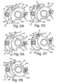
- Figure 24 is a simplified bottom plan view, similar to Figure 20, of selected parts of the shift position control mechanism for the rear bicycle control device (certain parts removed for purposes of illustration) showing the position maintaining pawl being moved to a shift position maintaining position and the winding pawl moving back to the initial rest position due to the release of the operating member (shift lever);
- Figure 25 is a simplified bottom plan view of selected parts of the shift position control mechanism for the rear bicycle control device (certain parts removed for purposes of illustration) showing the shift position control mechanism being moved to a wire unwinding or releasing position after movement of the position maintaining pawl but prior to movement of the position ratchet;
- Figure 26 is a simplified bottom plan view of selected parts of the shift position control mechanism for the rear bicycle control device (certain parts removed for purposes of illustration) showing the position maintaining pawl being moved to a shift position maintaining position, the position ratchet moving to the next shift position and the winding pawl moving back to the initial rest position due to the release of the operating member (shift lever);
- Figure 27 is a simplified bottom plan view, similar to Figure 25, of selected parts of the shift position control mechanism for the rear bicycle control device (certain parts removed for purposes of illustration) showing the shift position control mechanism being moved to a wire unwinding or releasing position after movement of the position maintaining pawl but prior to movement of the position ratchet; and
- Figure 28 is a simplified bottom plan view, similar to Figure 26, of selected parts of the shift position control mechanism for the rear bicycle control device (certain parts removed for purposes of illustration) showing the position maintaining pawl being moved to a shift position maintaining position, the position ratchet moving to the next shift position and the winding pawl moving back to the initial rest position due to the release of the operating member (shift lever).
- a bicycle 10 is illustrated with a pair of bicycle shift control mechanism or devices 12a and 12b mounted on a bicycle handlebar 13 in accordance with one embodiment of the present invention.
- the bicycle shift control device 12a is a left hand side shifting unit that is operated by the rider's left hand to control a front derailleur 14.
- the bicycle shift control device 12a is preferably operatively coupled to the front derailleur 14 via a shift control cable 15.
- the bicycle shift control device 12b is a right hand side shifting unit that is operated by the rider's right hand to control a rear derailleur 16.
- the bicycle shift control device 12b is preferably operatively coupled to the rear derailleur 16 via a shift control cable 17.
- the bicycle control devices 12a and 12b are substantially identical, except for the shifting units have been modified in the number of gears that can be shifted.
- the left hand side bicycle shift control device 12a is operatively coupled to a front derailleur 14, while the bicycle shift control device 12b is operatively coupled to the rear derailleur 16.
- the control devices can be switched so that the rider can operate the front derailleur 14 and the rear derailleur 16 with opposite hands.
- the left hand side bicycle shift control device 12a is essentially identical in construction and operation to the control device 12b, except that it is a mirror image of the control device 12a and the number of shift positions for the left hand side bicycle control device12a is different.
- the cables 15 and 17 are conventional bicycle cables that have an outer casing the covers an inner wire.
- the left hand side bicycle shift control device 12a will be considered herein as the “front bicycle shift control device”
- the bicycle shift control device 12b will be considered herein as the “rear bicycle shift control device”.
- the front bicycle shift control device 12a preferably has a housing that been removed for the purposes of illustration in Figures 3-8.
- the front bicycle shift control device 12a is configured and arranged such that an inner shift wire 15a of the shift control cable 15 can be released in only a single-stage at a time in a single gear shift operation as explained below.
- the front bicycle shift control device 12a basically has a handlebar mounting member 31 with a main pivot shaft 32 mounted thereon, a wire take up assembly 33 pivotally mounted on the main pivot shaft 32, a shift position maintaining assembly 34 operatively mounted on the main pivot shaft 32, an operating member 35 pivotally mounted on the main pivot shaft 32, a shift wire winding assembly 36 pivotally mounted on the operating member 35 and a shift wire releasing assembly 37 mounted on the main pivot shaft 32 to be operatively moved by the operating member 35.
- the front bicycle shift control device 12a is illustrated in the rest position.
- Figure 3 is a bottom perspective view of the front bicycle shift control device 12a
- Figure 4 is a bottom plan view of the front bicycle shift control device 12a.
- Figure 5 is a partial cross sectional view of the front bicycle shift control device 12a as viewed along section line 5-5 of Figure 4.
- the operating member 35 is pivoted about the main pivot shaft 32 in a counter clockwise direction to perform a cable pulling (winding) operation.
- the operating member 35 is pivoted about the main pivot shaft 32 in a clockwise direction to perform a cable releasing (unwinding) operation.
- the rear bicycle shift control device 12b preferably has a housing that been removed for the purposes of illustration in Figures 9-12.
- the rear bicycle shift control device 12b is configured and arranged such that an inner shift wire 15a of the shift control cable 15 can be released in only a single-stage at a time in a single gear shift operation as explained below.
- the rear bicycle shift control device 12b includes basically same parts as the front bicycle shift control device 12a, except that the parts are mirror images and some of the parts have been configured to provide more shift positions.
- the rear bicycle shift control device 12b has a handlebar mounting member 31' with a main pivot shaft 32' mounted thereon, a wire take up assembly 33' pivotally mounted on the main pivot shaft 32', a shift position maintaining assembly 34' operatively mounted on the main pivot shaft 32', an operating member 35' pivotally mounted on the main pivot shaft 32', a shift wire winding assembly 36' pivotally mounted on the operating member 35' and a shift wire releasing assembly 37' mounted on the main pivot shaft 32' to be operatively moved by the operating member 35'.
- FIG. 9 is a bottom plan view of the rear bicycle shift control device 12b
- Figure 10 shows, from a bottom plan view, the operating member 35' being pivoted about the main pivot shaft 32' in a clockwise direction to perform a cable pulling (winding) operation.
- the cable pulling (winding) and releasing (unwinding) operations of the rear bicycle shift control device 12b are in opposite directions relative to the front bicycle shift control device 12a.
- the parts of the rear bicycle shift control device 12b may not be discussed in detail herein.
- the handlebar mounting member 31 basically has a clamping section 31a and a shift unit supporting section 31b.
- the clamping section 31a is preferably a split bore type of clamping arrangement in which the diameter of the bore is varied by a fixing bolt 38 in a conventional manner.
- the clamping section 31a is relatively conventional in construction, and thus, will not be discussed or illustrated in further detail herein.
- the shift unit supporting section 31b has a non-circular mounting hole 39 for non-rotatably receiving the main pivot shaft 32 therein.
- the shift unit supporting section 31b also has a plurality of first spring receiving holes 40, a pivot pin mounting hole 41, and a second spring receiving holes 42. The holes 40, 41 and 42 will be discussed later.
- the main pivot shaft 32 is preferably a bolt having a head section 32a and a threaded section 32b.
- the threaded section 32b has left hand threads.
- the head section 32a is non-rotatably received in the mounting hole 39 formed in the shift unit supporting section 31 b of the handlebar mounting member 31.
- the threaded section 32b is configured to receive a nut 43 and a washer 44 to secure portions of the wire take up assembly 33, the shift position maintaining assembly 34, the operating member 35, and the shift wire releasing assembly 37 thereon.
- the main pivot shaft 32 forms a main pivot axis of the front bicycle shift control device 12a.
- the wire take up assembly 33 is mounted on the main pivot shaft 32 for winding and unwinding the shift wire 15a.
- the wire take up assembly 33 is configured and arranged to wind and unwind the shift wire 15a in response to movement of the operating member 35.
- the wire take up assembly 33 basically has a wire take up member 51, a spring or biasing element 52 and a tubular support member 53.
- the wire take up member 51 has a circular center opening 51a that is rotatably mounted on the tubular support member 53.
- the wire take up member 51 is a spool that has a wire attachment opening 51b configured and arranged to attach one end of the shift wire 15a thereto in a conventional manner.
- the wire take up member 51 is configured to rotate on the main pivot shaft 32 to wind the shift wire 15a about its peripheral edge surface when rotated in a first (winding) rotational direction about the main pivot axis and to unwind the shift wire 15a from its peripheral edge surface when rotated in a second (release) rotational direction about the main pivot axis.
- the wire take up member 51 also has an axially extending hole 51c that is configured and arranged for connecting the biasing element 52 thereto.
- the wire take up member 51 also has a non-circular projection 51d formed on one of its axially facing surfaces for coupling a portion of the shift positioning maintaining assembly 34 thereto as explained later.
- the biasing element 52 is configured to urge the wire take up member 51 in the second (release) rotational direction such that the shift wire 15a unwinds from the peripheral edge surface of the wire take up member 51.
- the biasing element 52 is preferably a torsion spring that has a first end 52a located in the hole 51c of the wire take up member 51, and a second end 52b located in one of the spring receiving holes 40 formed in the shift unit supporting section 31b of the handlebar mounting member 31.
- the wire take up member 51 is urged in the second (wire releasing or unwinding) rotational direction relative to the handlebar mounting member 31 by the urging force of the biasing element 52.
- the shift position maintaining assembly 34 is configured and arranged to maintain the wire take up member 51 in one of a plurality of shift positions against the urging force of the biasing element 52.
- the tubular support member 53 is preferably a one-piece, unitary member that includes a tubular section 53a and a washer section 53b.
- the second end 52b of the biasing element 52 engages a notch 53c in the washer section 53b so that the tubular support member 53 does not rotate relative to the main pivot shaft 32.
- the tubular support member 53 is not rotatably mounted on the main pivot shaft 32 with the wire take up member 51 and the biasing element 52 disposed on the tubular section 53a of the tubular support member 53.
- the tubular support member 53 is configured and arranged to act as a bearing surface for the wire take up member 51.
- the shift positioning maintaining assembly 34 basically has a positioning ratchet 55, a shift position maintaining pawl 56, a spring or biasing element 57 and a mounting or pivot pin 58.
- the shift positioning maintaining assembly 34 is configured and arranged to selectively hold the wire take up member 51 in one of its plurality of shift positions.
- the shift positioning maintaining assembly 34 is operatively controlled by movement of the operating member 35.
- the positioning ratchet 55 is a plate like member that has a non-circular center opening 55a that is non-rotatably mounted on the projection 51d of the wire take up member 51.
- the wire take up member 51 and the positioning ratchet 55 rotate together on the main pivot shaft 32.
- the main pivot axis of the positioning ratchet 55 is concentric with the rotational axis of the wire take up member 51.
- the positioning ratchet 55 has an outer peripheral edge that forms a plurality of winding teeth or projections 55b, a plurality of positioning teeth or projections 55c and a plurality of movement restricting teeth 55d.
- the winding teeth 55b of the positioning ratchet 55 are concentrically arranged with respect to the main pivot axis.
- the shift wire winding assembly 36 selectively engages the winding teeth 55b of the positioning ratchet 55 when the operating member 35 is rotated in the counterclockwise direction as view in a bottom plan view as seen in Figure 6.
- the shift wire winding assembly 36 is normally disengaged from the winding teeth 55b of the positioning ratchet 55 when the operating member 35 is in the rest position as seen in Figure 4 or when the operating member 35 is moved to a wire unwinding or releasing position as seen in Figure 7.
- the number of the winding teeth 55b of the positioning ratchet 55 depends on the desired number of shift positions.
- the positioning teeth 55c of the positioning ratchet 55 are non-concentrically arranged with respect to the main pivot axis so that the positioning teeth 55c form a stair shaped arrangement.
- the number of the positioning teeth 55c of the positioning ratchet 55 depends on the desired number of shift positions.
- the stair shaped arrangement of the positioning teeth 55c of the positioning ratchet 55 are arranged such that a radial distance of each positioning tooth relative to the main pivot axis progressively increases in a winding direction of the wire take up member 51.
- the shift position maintaining pawl 56 normally engages the positioning teeth 55c of the positioning ratchet 55 when the operating member 35 is in the rest position as seen in Figure 4 to hold the wire take up member 51 and the positioning ratchet 55 from rotating about the main pivot shaft 32.
- the biasing force of the spring or biasing element 57 normally urges the shift position maintaining pawl 56 against one of the positioning teeth 55c of the positioning ratchet 55 to maintain a current shift position.
- the positioning teeth 55c form a stair shaped arrangement with the radial distance of each positioning tooth progressively increases in a winding direction of the wire take up member 51, the positioning ratchet 55 and the wire take up member 51 can rotate together in the winding direction even though the shift position maintaining pawl 56 is urged against one of the positioning teeth 55c of the positioning ratchet 55.
- this stair shaped arrangement of the positioning teeth 55c prevents the positioning ratchet 55 and the wire take up member 51 from rotating due to the biasing force of the biasing element 52 (i.e., the wire take up member return spring) that urges the wire take up member 51 in the wire unwinding direction.
- the movement restricting teeth 55d of the positioning ratchet 55 are non-concentrically arranged with respect to the main pivot axis so that the movement restricting teeth 55d form a stair shaped arrangement.
- the number of the movement restricting teeth 55d of the positioning ratchet 55 depends on the desired number of shift positions.
- the stair shaped arrangement of the movement restricting teeth 55d of the positioning ratchet 55 are arranged such that a radial distance of each movement restricting tooth relative to the main pivot axis progressively decreases in a winding direction of the wire take up member 51.
- the shift position maintaining pawl 56 is normally disengaged from the movement restricting teeth 55d of the positioning ratchet 55 by a predetermined distance when the operating member 35 is in the rest position as seen in Figure 4.
- the biasing force of the spring or biasing element 57 normally urges the shift position maintaining pawl 56 away from one of the movement restricting teeth 55d of the positioning ratchet 55.
- the shift position maintaining pawl 56 is moved into engagement with the movement restricting teeth 55d of the positioning ratchet 55 against the urging force of the biasing element 57 when the operating member 35 is moved to a wire releasing or unwinding position as seen in Figure 7.
- the positioning teeth 55c of the positioning ratchet 55 are then disengaged from the shift position maintaining pawl 56. Since the movement restricting teeth 55d form a stair shaped arrangement with the radial distance of each positioning tooth progressively decreases in a winding direction of the wire take up member 51, the positioning ratchet 55 and the wire take up member 51 can rotate together in the unwinding direction due to the biasing force of the biasing element 52 (i.e., the wire take up member return spring) that urges the wire take up member 51 in the wire unwinding direction.
- the biasing element 52 i.e., the wire take up member return spring
- the positioning ratchet 55 and the wire take up member 51 can only rotate together for one shift position in the unwinding direction due to the positioning teeth 55c forming a stair shaped arrangement with the radial distance of each positioning tooth progressively increases in a winding direction of the wire take up member 51.
- the positioning teeth 55c are configured and arranged such that the next one of the positioning teeth 55c contacts the shift position maintaining pawl 56 to stop rotation of the positioning ratchet 55 and the wire take up member 51.
- the shift position maintaining pawl 56 is pivots mounted on the pivot pin 58 to selectively engage the positioning teeth 55c and the movement restricting teeth 55d.
- the shift position maintaining pawl 56 includes a centrally located pivot hole 56a, a release engagement abutment 56b, a position maintaining portion 56c and a movement restricting portion 56d.
- the shift position maintaining pawl 56 is a one-piece, unitary member that is configured such that the position maintaining portion 56c and the movement restricting portion 56d are arranged to move together about a single pivot axis formed by the pivot pin 58.
- the pivot pin 58 is located in the pivot hole 56a such that the shift position maintaining pawl 56 selectively pivots into engagement with either the positioning teeth 55c or the movement restricting teeth 55d.
- the biasing element 57 urges the shift position maintaining pawl 56 into engagement with the positioning teeth 55c of the positioning ratchet 55 and away from the movement restricting teeth 55d of the positioning ratchet 55.
- the release engagement abutment 56b is located near the position maintaining portion 56c so that the shift position maintaining pawl 56 can be pivoted away from the positioning teeth 55c and into engagement with the movement restricting teeth 55d by the shift wire releasing assembly 37.
- the position maintaining portion 56c is arranged to selectively engage the positioning teeth 55c of the positioning ratchet 55, while the movement restricting portion 56d is arranged to selectively engage the movement restricting teeth 55d of the positioning ratchet 55.
- the position maintaining portion 56c is normally urged into engagement with the positioning teeth 55c of the positioning ratchet 55 by the biasing element 57 and the movement restricting portion 56d is normally spaced away from the movement restricting teeth 55d of the positioning ratchet 55.
- the spring or biasing element 57 is preferably a torsion spring that has a first end 57a located in the hole 42 of the handlebar mounting member 31, and a second end 57b loops around the shift position maintaining pawl 56. As mentioned above, the biasing element 57 urges the shift position maintaining pawl 56 into engagement with the positioning teeth 55c of the positioning ratchet 55 and away from the movement restricting teeth 55d of the positioning ratchet 55.
- the mounting or pivot pin 58 is fixedly secured to the handlebar mounting member 31 and pivotally supports the shift position maintaining pawl 56.
- the coiled portion of the biasing element 57 is disposed on the pivot pin 58.
- a clip 58a is used to maintain the shift position maintaining pawl 56 and the biasing element 57 on the pivot pin 58.
- the operating member 35 is a lever that is pivotally mounted on the main pivot shaft 32.
- the operating member 35 is configured and arranged to rotate about the rotational axis of the wire take up member 51, which is concentric with the main pivot axis of the positioning ratchet 55.
- the operating member 35 basically includes an internal mounting portion 35a and an external rider operating portion 35b.
- the internal mounting portion 35a is configured and arranged to pivot around the outer periphery of the main pivot shaft 32 such that the operating member 35 can move between from the rest position to either a shift winding position or a shift releasing position.
- the internal mounting portion 35a preferably includes a mounting tab 35c for supporting the shift wire winding assembly 36.
- the internal mounting portion 35a also includes a cutout 35d that engages a return spring 61 for applying urging force on the operating member 35 to hold in the operating member 35 in the rest position.
- the return spring 61 is operatively coupled to the operating member 35 to urge the operating member 35 to a rest position.
- the return spring 61 is preferably a torsion spring having a first end 61a engaging the cutout 35d of the operating member 35 and a second end 61b engaging a stationary part of the shift wire releasing assembly 37 as explained below.
- the return spring 61 biases the operating member 35 in a clockwise direction as seen in Figures 3, 4, 5 and 6. Accordingly, the operating member 35 and the return spring 61 cooperate together such that the operating member 35 has a trigger action in which the operating member 35 automatically springs back to its rest position after being moved to a shift winding position.
- the shift wire winding assembly 36 basically has a winding pawl 71, a return spring or biasing element 72 and a mounting or pivot pin 73.
- the shift wire winding assembly 36 is mounted on the operating member 35 so as to move therewith.
- the shift wire winding assembly 36 is configured and arranged such that the rider can easily operate the operating member 35 to perform a shift winding operation as Figure 6.
- the shift wire winding assembly 36 is normally disengaged from the winding teeth 55b of the positioning ratchet 55 when the operating member 35 is in the rest position as seen in Figure 4 or when the operating member 35 is moved to a wire unwinding or releasing position as seen in Figure 7.
- the winding pawl 71 is mounted to the mounting tab 35c via the mounting pin 73 that is riveted onto the mounting tab 35c.
- the winding pawl 71 is held on the mounting pin 73 by a retaining clip 74.
- the winding pawl 71 is biased in a counterclockwise direction by the biasing element 72 as seen in the bottom plan views of Figures 3, 4, 5 and 6.
- the winding pawl 71 is biased towards the peripheral edge of the positioning ratchet 55.
- the winding pawl 71 is normally held out of engagement from the positioning ratchet 55 by the shift wire releasing assembly 37 so that the winding pawl 71 doe not interfere with the rotation of the positioning ratchet 55 during a wire unwinding or releasing operation.
- the winding pawl 71 engages the winding teeth 55b of the positioning ratchet 55.
- the biasing element 72 of the shift wire winding assembly 36 is preferably a torsion spring that has its coiled portion mounted on the mounting pin 73.
- the biasing element 72 has a first end 72a engaging the winding pawl 71 and a second end 72b engaging the mounting tab 35c of the operating member 35.
- the winding pawl 71 is configured and arranged to selectively operate the shift positioning maintaining assembly 34 (i.e., rotate the positioning ratchet 55 and the wire take up member 51 together) when the operating member 35 is pivoted from its rest position to its shift winding position.
- the shift wire releasing assembly 37 basically has a release plate 81, a stationary control plate 82 and a return spring or biasing element 83.
- the shift wire releasing assembly 37 is operatively controlled by movement of the operating member 35.
- the shift wire releasing assembly 37 moves the shift position maintaining pawl 56 to release the positioning ratchet 55 so that the positioning ratchet 55 and the wire take up member 51 rotate together due to the biasing element 52.
- the release plate 81 is pivotally mounted on the main pivot shaft 32.
- the release plate 81 is configured and arranged to rotate about the rotational axis of the wire take up member 51, which is concentric with the main pivot axis of the positioning ratchet 55.
- the release plate 81 has a center hole 81a, a release activating projection or tab 81b, an operating member engagement projection or tab 81c and a cutout 81d.
- the release plate 81 is a rigid plate like member that is preferably formed of a hard rigid material such as a metallic plate material.
- the center hole 81a receives the main pivot shaft 32 so that the release plate 81 is pivots about the main pivot axis.
- the release activating projection 81b is configured and arranged to selectively engage the release engagement abutment 56b of the shift position maintaining pawl 56 to pivot the position maintaining portion 56c of the shift position maintaining pawl 56 out of engagement with the positioning teeth 55c of the positioning ratchet 55 and move the movement restricting portion 56d into engagement with the movement restricting teeth 55d of the positioning ratchet 55.
- Movement of the release plate 81 to the shift releasing position is accomplished by the operating member 35 engaging the operating member engagement projection 81c such that the release plate 81 is pivoted about the main pivot shaft 32 against the urging force of the biasing element 83.
- the biasing element 83 urges the release plate 81 to its rest position, which in turn transfers the biasing force of the biasing element 83 to the operating member 35 via the operating member engagement projection 81c, which contacts the winding pawl 71 on the operating member 35.
- the biasing elements 61 and 83 counterbalance each other to hold the operating member 35 in its rest position.
- the stationary control plate 82 is mounted on the main pivot shaft 32 and the pivot pin 58 so that the stationary control plate 82 does not move.
- the stationary control plate 82 basically has a main mounting hole 82a, a secondary mounting hole 82b, a winding pawl control projection or tab 82c, a spring attachment projection or tab 82d and a release plate stop or projection 82e.
- the stationary control plate 82 is a rigid plate like member that is preferably formed of a hard rigid material such as a metallic plate material.
- the main mounting hole 82a receives the main pivot shaft 32, while the secondary mounting hole 82b the pivot pin 58 to prevent movement of the stationary control plate 82.
- the winding pawl control projection 82c is configured and arranged to selectively engage the winding pawl 71 so that, in the rest position, the winding pawl 71 is normally held out of engagement from the positioning ratchet 55. Thus, the winding pawl control projection 82c prevents the winding pawl 71 from interfering with the rotation of the positioning ratchet 55 during a wire unwinding or releasing operation.
- the spring attachment projection 82d is configured and arranged so that the second end 61b of the biasing element 61 is looped thereon.
- the release plate stop 82e is configured and arranged to stop the rotational movement of the release plate 81 from the urging force of the biasing element 83.
- the biasing element 83 is a U-shaped member that has a first end 83a contacting the stationary control plate 82 and a second end 83b contacting the release plate 81.
- the cutout 81d of the release plate 81 is configured and arranged to prevent interference with the first end 83a of the biasing element 83.
- the parts of the rear bicycle shift control device 12b will now be discussed. Since the parts of the rear bicycle shift control device 12b are basically mirror images of the parts of the front bicycle shift control device 12a, except that some of the parts have been configured to provide more shift positions, the parts of the rear bicycle shift control device 12b will not be discussed in great detail.
- the wire take up assembly 33' of the rear bicycle shift control device 12b has a wire take up member 51', a spring or biasing element 52' and a tubular support member 53'.
- the shift position maintaining assembly 34' basically has a positioning ratchet 55', a shift position maintaining pawl 56', a spring or biasing element 57' and a mounting or pivot pin 58'.
- the positioning ratchet 55' has an outer peripheral edge that forms a plurality of winding teeth or projections 55b', a plurality of positioning teeth or projections 55c' and a plurality of movement restricting teeth 55d'.
- the shift position maintaining pawl 56' includes a release engagement abutment 56b', a position maintaining portion 56c' and a movement restricting portion 56d'.
- the operating member 35' has a trigger action in which the operating member 35' automatically springs back to its rest position after being moved to a shift winding position by a return spring 61'.
- the shift wire winding assembly 36' basically has a winding pawl 71', a return spring or biasing element 72' and a mounting or pivot pin 73'.
- the shift wire releasing assembly 37' basically has a release plate 81', a stationary control plate 82' and a return spring or biasing element 83'.
- a shift winding operation of the rear bicycle shift control device 12b is illustrated to show the movement of the shift position maintaining pawl 56' by the winding pawl 71'.
- the shift position control mechanism of the rear bicycle shift control device 12b is in the rest position.
- the operating member 35' of the shift position control mechanism for the rear bicycle shift control device 12b is moved to a wire winding position causing the positioning ratchet 55' to rotate in a wire winding direction.
- the position maintaining pawl 56' is shown prior to being moved back to a shift position maintaining position by the biasing element 57'.
- FIGs 24-28 a shift releasing operation of the rear bicycle shift control device 12b is illustrated to show the movement of the shift position maintaining pawl 56' by the release plate 81'.
- Figure 24 shows of the shift position control mechanism for the rear bicycle shift control device 12b in the rest position.
- the release plate 81' is moved to a wire unwinding or releasing position causing the position maintaining pawl 56' to rotate into engagement with the movement restricting teeth 55d of the positioning ratchet 55.
- the position ratchet 55' can rotate due to the force of the biasing element 52' (not shown in Figures 25 and 26).
- Figures 27 and 28 show another shift releasing operation of the rear bicycle shift control device 12b.
Applications Claiming Priority (1)
| Application Number | Priority Date | Filing Date | Title |
|---|---|---|---|
| US11/266,484 US7721621B2 (en) | 2005-11-04 | 2005-11-04 | Bicycle shift control mechanism |
Publications (3)
| Publication Number | Publication Date |
|---|---|
| EP1783043A2 true EP1783043A2 (fr) | 2007-05-09 |
| EP1783043A3 EP1783043A3 (fr) | 2008-01-16 |
| EP1783043B1 EP1783043B1 (fr) | 2010-07-07 |
Family
ID=37533255
Family Applications (1)
| Application Number | Title | Priority Date | Filing Date |
|---|---|---|---|
| EP06022722A Active EP1783043B1 (fr) | 2005-11-04 | 2006-10-31 | Dispositif de commande de changement de vitesses pour bicyclette |
Country Status (7)
| Country | Link |
|---|---|
| US (1) | US7721621B2 (fr) |
| EP (1) | EP1783043B1 (fr) |
| JP (1) | JP2007126132A (fr) |
| CN (1) | CN1958389B (fr) |
| BR (1) | BRPI0604506A (fr) |
| DE (1) | DE602006015272D1 (fr) |
| TW (1) | TWI296987B (fr) |
Cited By (2)
| Publication number | Priority date | Publication date | Assignee | Title |
|---|---|---|---|---|
| EP1985532A3 (fr) * | 2007-04-26 | 2009-06-24 | Shimano Inc. | Dispositif de positionnement de composant de bicyclette |
| EP3398845A4 (fr) * | 2015-12-29 | 2019-08-28 | S-Ride Bicycle Components (Foshan) Co., Ltd. | Dérailleur de bicyclette |
Families Citing this family (15)
| Publication number | Priority date | Publication date | Assignee | Title |
|---|---|---|---|---|
| US7849764B2 (en) * | 2006-12-20 | 2010-12-14 | Shimano (Singapore) Pte., Ltd. | Bicycle shift operating device |
| US9434443B2 (en) * | 2008-08-18 | 2016-09-06 | Shimano Inc. | Cable operating mechanism |
| US9327792B2 (en) | 2011-01-28 | 2016-05-03 | Paha Designs, Llc | Gear transmission and derailleur system |
| US9033833B2 (en) | 2011-01-28 | 2015-05-19 | Paha Designs, Llc | Gear transmission and derailleur system |
| US10207772B2 (en) | 2011-01-28 | 2019-02-19 | Paha Designs, Llc | Gear transmission and derailleur system |
| US8534156B2 (en) * | 2011-05-26 | 2013-09-17 | Shimano Inc. | Bicycle shift operating device |
| US9327793B2 (en) * | 2011-10-01 | 2016-05-03 | Shimano Inc. | Bicycle operating device |
| US9132887B2 (en) * | 2012-02-24 | 2015-09-15 | Shimano Inc. | Bicycle operating device |
| US8720301B2 (en) * | 2012-02-24 | 2014-05-13 | Shimano Inc. | Bicycle operating device |
| US8746106B2 (en) * | 2012-03-08 | 2014-06-10 | Shimano Inc. | Bicycle operating device |
| JP2015223985A (ja) * | 2014-05-29 | 2015-12-14 | 株式会社シマノ | 自転車用の操作装置 |
| CN106995035B (zh) * | 2017-04-17 | 2022-05-03 | 珠海蓝图控制器科技有限公司 | 一种自行车换挡器 |
| JP2019064356A (ja) * | 2017-09-29 | 2019-04-25 | 株式会社シマノ | 自転車用操作装置 |
| CN108622307B (zh) * | 2018-03-15 | 2024-04-02 | 宁波日骋车业有限公司 | 一种自行车指拨式变速器及其控制方法 |
| US10435113B1 (en) * | 2018-04-03 | 2019-10-08 | Shimano Inc. | Bicycle operating device |
Citations (1)
| Publication number | Priority date | Publication date | Assignee | Title |
|---|---|---|---|---|
| EP1232940A2 (fr) | 1996-01-19 | 2002-08-21 | Shimano Inc. | Dispositif de changement de vitesse pour bicyclette |
Family Cites Families (10)
| Publication number | Priority date | Publication date | Assignee | Title |
|---|---|---|---|---|
| JP3065655B2 (ja) * | 1990-11-13 | 2000-07-17 | 株式会社シマノ | 自転車用変速操作装置 |
| IT1245445B (it) * | 1991-03-11 | 1994-09-20 | Campagnolo Srl | Gruppo di comando del cambio e del freno per una bicicletta |
| DE9414961U1 (de) | 1993-07-23 | 1995-01-05 | Elsen Heinrich | Fahrradgangschaltung |
| JP2607289Y2 (ja) * | 1993-12-28 | 2001-05-28 | 株式会社シマノ | 自転車用変速操作装置 |
| FR2750669B1 (fr) | 1996-07-03 | 1998-11-06 | Savard Franck | Dispositif monocommande de manoeuvre synchronisee de deux derailleurs avant et arriere d'un velo |
| US5829313A (en) * | 1997-01-13 | 1998-11-03 | Shimano Inc. | Bicycle derailleur shifting mechanism having indexing configured for use with variety of chain sprocket sets |
| US6484603B2 (en) * | 1997-12-05 | 2002-11-26 | Sram Deutschland Gmbh | Selector for a bicycle gear mechanism |
| ITTO20010011A1 (it) * | 2001-01-11 | 2002-07-11 | Campagnolo Srl | Gruppo integrato di comando del cambio e del freno per una bicicletta. |
| DE10205278B4 (de) * | 2002-02-08 | 2019-03-14 | Sram Deutschland Gmbh | Freigabemechanismus |
| EP1378438A1 (fr) | 2002-07-05 | 2004-01-07 | Shimano Inc. | Dispositif de commande de changement de vitesses pour bicyclette |
-
2005
- 2005-11-04 US US11/266,484 patent/US7721621B2/en not_active Expired - Fee Related
-
2006
- 2006-06-27 TW TW095123077A patent/TWI296987B/zh active
- 2006-07-20 CN CN200610099444.0A patent/CN1958389B/zh not_active Expired - Fee Related
- 2006-10-23 JP JP2006287360A patent/JP2007126132A/ja active Pending
- 2006-10-31 EP EP06022722A patent/EP1783043B1/fr active Active
- 2006-10-31 BR BRPI0604506-5A patent/BRPI0604506A/pt not_active IP Right Cessation
- 2006-10-31 DE DE602006015272T patent/DE602006015272D1/de active Active
Patent Citations (1)
| Publication number | Priority date | Publication date | Assignee | Title |
|---|---|---|---|---|
| EP1232940A2 (fr) | 1996-01-19 | 2002-08-21 | Shimano Inc. | Dispositif de changement de vitesse pour bicyclette |
Cited By (3)
| Publication number | Priority date | Publication date | Assignee | Title |
|---|---|---|---|---|
| EP1985532A3 (fr) * | 2007-04-26 | 2009-06-24 | Shimano Inc. | Dispositif de positionnement de composant de bicyclette |
| US9334020B2 (en) | 2007-04-26 | 2016-05-10 | Shimano Inc. | Bicycle component positioning device |
| EP3398845A4 (fr) * | 2015-12-29 | 2019-08-28 | S-Ride Bicycle Components (Foshan) Co., Ltd. | Dérailleur de bicyclette |
Also Published As
| Publication number | Publication date |
|---|---|
| TW200718604A (en) | 2007-05-16 |
| EP1783043A3 (fr) | 2008-01-16 |
| CN1958389A (zh) | 2007-05-09 |
| TWI296987B (en) | 2008-05-21 |
| EP1783043B1 (fr) | 2010-07-07 |
| CN1958389B (zh) | 2011-09-07 |
| US7721621B2 (en) | 2010-05-25 |
| DE602006015272D1 (de) | 2010-08-19 |
| US20070137386A1 (en) | 2007-06-21 |
| JP2007126132A (ja) | 2007-05-24 |
| BRPI0604506A (pt) | 2007-08-28 |
Similar Documents
| Publication | Publication Date | Title |
|---|---|---|
| EP1783043B1 (fr) | Dispositif de commande de changement de vitesses pour bicyclette | |
| US7665382B2 (en) | Bicycle shift control device | |
| US7628095B2 (en) | Bicycle shifting mechanism | |
| EP1762484B1 (fr) | Mécanisme de changement de vitesse pour bicyclette | |
| US9327793B2 (en) | Bicycle operating device | |
| US7665383B2 (en) | Bicycle shift control device | |
| US9132887B2 (en) | Bicycle operating device | |
| EP2075187B1 (fr) | Dispositif de changement de vitesses de bicyclette | |
| US8181553B2 (en) | Position control mechanism for bicycle control device | |
| US7392723B2 (en) | Bicycle shift control mechanism | |
| US10450034B2 (en) | Bicycle operating device | |
| US8720301B2 (en) | Bicycle operating device | |
| US7124873B2 (en) | Shift and brake control device | |
| US20150210342A1 (en) | Bicycle component positioning device | |
| EP2078666B1 (fr) | Dispositif de fonctionnement des vitesses de bicyclette | |
| US20080148898A1 (en) | Bicycle shift operating device | |
| US8375823B2 (en) | Bicycle shift control device | |
| US9056648B2 (en) | Bicycle component positioning device | |
| US8161841B2 (en) | Cable operating mechanism | |
| US8746105B2 (en) | Bicycle operating device | |
| US8528442B2 (en) | Bicycle component positioning device | |
| EP2246247B1 (fr) | Dispositif d'actionnement de transmission de bicyclette | |
| EP2078667B1 (fr) | Dispositif de fonctionnement des vitesses de bicyclette |
Legal Events
| Date | Code | Title | Description |
|---|---|---|---|
| PUAI | Public reference made under article 153(3) epc to a published international application that has entered the european phase |
Free format text: ORIGINAL CODE: 0009012 |
|
| AK | Designated contracting states |
Kind code of ref document: A2 Designated state(s): AT BE BG CH CY CZ DE DK EE ES FI FR GB GR HU IE IS IT LI LT LU LV MC NL PL PT RO SE SI SK TR |
|
| AX | Request for extension of the european patent |
Extension state: AL BA HR MK YU |
|
| PUAL | Search report despatched |
Free format text: ORIGINAL CODE: 0009013 |
|
| AK | Designated contracting states |
Kind code of ref document: A3 Designated state(s): AT BE BG CH CY CZ DE DK EE ES FI FR GB GR HU IE IS IT LI LT LU LV MC NL PL PT RO SE SI SK TR |
|
| AX | Request for extension of the european patent |
Extension state: AL BA HR MK YU |
|
| 17P | Request for examination filed |
Effective date: 20080222 |
|
| 17Q | First examination report despatched |
Effective date: 20080409 |
|
| AKX | Designation fees paid |
Designated state(s): DE FR IT NL |
|
| GRAP | Despatch of communication of intention to grant a patent |
Free format text: ORIGINAL CODE: EPIDOSNIGR1 |
|
| RIN1 | Information on inventor provided before grant (corrected) |
Inventor name: KAWAKAMI, TATSUYA |
|
| GRAS | Grant fee paid |
Free format text: ORIGINAL CODE: EPIDOSNIGR3 |
|
| GRAA | (expected) grant |
Free format text: ORIGINAL CODE: 0009210 |
|
| AK | Designated contracting states |
Kind code of ref document: B1 Designated state(s): DE FR IT NL |
|
| REF | Corresponds to: |
Ref document number: 602006015272 Country of ref document: DE Date of ref document: 20100819 Kind code of ref document: P |
|
| REG | Reference to a national code |
Ref country code: NL Ref legal event code: VDEP Effective date: 20100707 |
|
| PG25 | Lapsed in a contracting state [announced via postgrant information from national office to epo] |
Ref country code: NL Free format text: LAPSE BECAUSE OF FAILURE TO SUBMIT A TRANSLATION OF THE DESCRIPTION OR TO PAY THE FEE WITHIN THE PRESCRIBED TIME-LIMIT Effective date: 20100707 |
|
| PLBE | No opposition filed within time limit |
Free format text: ORIGINAL CODE: 0009261 |
|
| STAA | Information on the status of an ep patent application or granted ep patent |
Free format text: STATUS: NO OPPOSITION FILED WITHIN TIME LIMIT |
|
| 26N | No opposition filed |
Effective date: 20110408 |
|
| REG | Reference to a national code |
Ref country code: DE Ref legal event code: R097 Ref document number: 602006015272 Country of ref document: DE Effective date: 20110408 |
|
| PG25 | Lapsed in a contracting state [announced via postgrant information from national office to epo] |
Ref country code: FR Free format text: LAPSE BECAUSE OF NON-PAYMENT OF DUE FEES Effective date: 20101102 |
|
| REG | Reference to a national code |
Ref country code: FR Ref legal event code: ST Effective date: 20110630 |
|
| PGFP | Annual fee paid to national office [announced via postgrant information from national office to epo] |
Ref country code: IT Payment date: 20161024 Year of fee payment: 11 |
|
| PG25 | Lapsed in a contracting state [announced via postgrant information from national office to epo] |
Ref country code: IT Free format text: LAPSE BECAUSE OF NON-PAYMENT OF DUE FEES Effective date: 20171031 |
|
| P01 | Opt-out of the competence of the unified patent court (upc) registered |
Effective date: 20230421 |
|
| PGFP | Annual fee paid to national office [announced via postgrant information from national office to epo] |
Ref country code: DE Payment date: 20230906 Year of fee payment: 18 |