EP1783013A2 - Hook or ring attaching unit - Google Patents
Hook or ring attaching unit Download PDFInfo
- Publication number
- EP1783013A2 EP1783013A2 EP06255655A EP06255655A EP1783013A2 EP 1783013 A2 EP1783013 A2 EP 1783013A2 EP 06255655 A EP06255655 A EP 06255655A EP 06255655 A EP06255655 A EP 06255655A EP 1783013 A2 EP1783013 A2 EP 1783013A2
- Authority
- EP
- European Patent Office
- Prior art keywords
- hook
- bolt
- base plate
- attaching unit
- cover member
- Prior art date
- Legal status (The legal status is an assumption and is not a legal conclusion. Google has not performed a legal analysis and makes no representation as to the accuracy of the status listed.)
- Withdrawn
Links
- 230000037431 insertion Effects 0.000 claims abstract description 10
- 238000003780 insertion Methods 0.000 claims abstract description 10
- 239000011347 resin Substances 0.000 claims abstract description 5
- 229920005989 resin Polymers 0.000 claims abstract description 5
- 125000006850 spacer group Chemical group 0.000 claims description 20
- 239000002184 metal Substances 0.000 claims description 13
- 238000005452 bending Methods 0.000 claims description 4
- 230000002401 inhibitory effect Effects 0.000 claims description 3
- 230000000694 effects Effects 0.000 abstract description 2
- 230000002093 peripheral effect Effects 0.000 description 5
- 230000000630 rising effect Effects 0.000 description 1
Images


Classifications
-
- F—MECHANICAL ENGINEERING; LIGHTING; HEATING; WEAPONS; BLASTING
- F16—ENGINEERING ELEMENTS AND UNITS; GENERAL MEASURES FOR PRODUCING AND MAINTAINING EFFECTIVE FUNCTIONING OF MACHINES OR INSTALLATIONS; THERMAL INSULATION IN GENERAL
- F16B—DEVICES FOR FASTENING OR SECURING CONSTRUCTIONAL ELEMENTS OR MACHINE PARTS TOGETHER, e.g. NAILS, BOLTS, CIRCLIPS, CLAMPS, CLIPS OR WEDGES; JOINTS OR JOINTING
- F16B37/00—Nuts or like thread-engaging members
- F16B37/14—Cap nuts; Nut caps or bolt caps
-
- B—PERFORMING OPERATIONS; TRANSPORTING
- B60—VEHICLES IN GENERAL
- B60R—VEHICLES, VEHICLE FITTINGS, OR VEHICLE PARTS, NOT OTHERWISE PROVIDED FOR
- B60R7/00—Stowing or holding appliances inside vehicle primarily intended for personal property smaller than suit-cases, e.g. travelling articles, or maps
- B60R7/08—Disposition of racks, clips, holders, containers or the like for supporting specific articles
- B60R7/10—Disposition of racks, clips, holders, containers or the like for supporting specific articles for supporting hats, clothes or clothes hangers
-
- F—MECHANICAL ENGINEERING; LIGHTING; HEATING; WEAPONS; BLASTING
- F16—ENGINEERING ELEMENTS AND UNITS; GENERAL MEASURES FOR PRODUCING AND MAINTAINING EFFECTIVE FUNCTIONING OF MACHINES OR INSTALLATIONS; THERMAL INSULATION IN GENERAL
- F16B—DEVICES FOR FASTENING OR SECURING CONSTRUCTIONAL ELEMENTS OR MACHINE PARTS TOGETHER, e.g. NAILS, BOLTS, CIRCLIPS, CLAMPS, CLIPS OR WEDGES; JOINTS OR JOINTING
- F16B45/00—Hooks; Eyes
- F16B45/002—Eyes
-
- F—MECHANICAL ENGINEERING; LIGHTING; HEATING; WEAPONS; BLASTING
- F16—ENGINEERING ELEMENTS AND UNITS; GENERAL MEASURES FOR PRODUCING AND MAINTAINING EFFECTIVE FUNCTIONING OF MACHINES OR INSTALLATIONS; THERMAL INSULATION IN GENERAL
- F16B—DEVICES FOR FASTENING OR SECURING CONSTRUCTIONAL ELEMENTS OR MACHINE PARTS TOGETHER, e.g. NAILS, BOLTS, CIRCLIPS, CLAMPS, CLIPS OR WEDGES; JOINTS OR JOINTING
- F16B45/00—Hooks; Eyes
- F16B45/005—Hooks; Eyes characterised by the material
- F16B45/012—Hooks; Eyes characterised by the material wire
-
- B—PERFORMING OPERATIONS; TRANSPORTING
- B60—VEHICLES IN GENERAL
- B60R—VEHICLES, VEHICLE FITTINGS, OR VEHICLE PARTS, NOT OTHERWISE PROVIDED FOR
- B60R22/00—Safety belts or body harnesses in vehicles
- B60R22/18—Anchoring devices
Definitions
- the present invention relates to a hook attaching unit for attaching a hook to a room inside of a motor vehicle.
- a hook locking a clothes hanger, a cord of a shopping bag or the like is provided in a side surface in a room inside of a motor vehicle.
- a hook in Japanese Unexamined Patent Publication No. 2000-316704 , there is disclosed a structure in which a tubular base portion provided with a hook main body is attached to a panel by a bolt.
- a hole for locking a hook-shaped hooking device is formed in the hook main body, and a bolt head is visible through this hole. As a result thereof, an outer appearance is not good.
- an object of the present invention is to provide a hook attaching unit which has an improved outer appearance, and an excellent workability for attaching a hook.
- a hook attaching unit in accordance with the present invention carried out for achieving the object mentioned above is constituted by a hook member in which a hook is rotatably attached to an end portion of a base plate, a bolt inserted to a bolt insertion hole provided in the base plate, and a resin cover member installed to the base plate so as to prevent the bolt from coming off from the base plate and cover a bolt head portion invisibly.
- the hook attaching unit in accordance with the present invention since the hook member, the cover member and the bolt are integrally assembled, it is not necessary to install the bolt point by point in a work field and install the cover member after attaching the hook, and a workability at a time of fastening is good. Further, since the cover member invisibly covers the bolt head portion, there can be obtained an effect that a safety and an improved outer appearance can be obtained.
- the hook is formed by bending a metal wire
- the base plate is structured such that a protruding piece made of a metal and provided in one end thereof is wound around the metal wire, and the hook is rotatably attached to the base plate. Accordingly, it is possible to rotatably attach the hook to the base plate. Further, since the hook and the base plate are made of the metal, a durability against an impact force is obtained in comparison with the resin structure. Accordingly, it is possible to install a seat belt anchor plate as mentioned below.
- the hook is formed in a D shape, and end portions of the metal wire are faced to each other at an interval in a linear portion of the D-shaped portion, a protrusion piece is provided in a leading end of the protruding piece, and the protrusion piece is pushed into the gap so as to form a stopper inhibiting the hook from moving. Accordingly, it is possible to inhibit the hook frommoving in a horizontal direction, and it is possible to prevent the hook from injuring the cover member.
- the structure may be made such that the bolt is constituted by a flange bolt, and the cover member is constituted by an annular basement portion pressing a flange in a state in which the bolt head portion is protruded from a center window portion, and a cover body flexibly connected to an end portion of the basement portion so as to release the bolt head portion at a time of fastening the bolt and cover the bolt head portion after fastening the bolt.
- the bolt is constituted by a flange bolt
- the cover member is constituted by an annular basement portion pressing a flange in a state in which the bolt head portion is protruded from a center window portion, and a cover body flexibly connected to an end portion of the basement portion so as to release the bolt head portion at a time of fastening the bolt and cover the bolt head portion after fastening the bolt.
- the structure may be made such that a short tube portion having an end surface is provided in a protruding manner around the bolt insertion hole of the base plate, and a stepped shaft portion protruding from the end surface at a time of being fitted into the short tube portion is provided below a neck of the bolt. Since it is possible to form a small gap between the end surface ot the short tube portion and the spacer even at a time when the spacer is installed to the bolt soas to be brought into contact with the step, it is possible to integrally rotate the bolt and the spacer without bringing the spacer into contact with the end surface.
- the stepped shaft portion is protruded from the end surface of the short tube portion at a length capable of installing a seat belt anchor, it is possible to install the seat belt anchor to the short tube portion. Accordingly, it is possible to use one mounting unit in common for attaching the hook and the seat belt anchor plate, and there is an advantage that it is possible to reduce the number of parts and improve a workability.
- the bolt is provided with a spacer with a female thread for adjusting a height, it is possible to adjust the height by the spacer. Accordingly, an upper surface of the cover body neither protrudes from a panel plate surface of a vehicle body nor be positioned at the depth.
- Figs. 1 and 2 are views showing a hook attaching unit in accordance with the present invention.
- the unit is constituted by a hook member 3 in which a hook 2 is rotatably attached to an end portion of a base plate 1, a bolt 5 inserted to a bolt insertion hole 11 provided in the base plate 1, and a resin cover member 8 in which a cover body 7 is connected to an annular basement portion 6 installed to the base plate 1.
- a spacer 9 is screwed with the bolt 5.
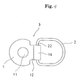
- Figs. 3 to 5 are views showing details of the hook member 3.
- the bolt insertion hole 11 is formed in a center of the approximately circular base plate 1, and a protruding piece 12 is provided in an end portion thereof.
- the hook 2 is formed by bending a metal wire in a D shape, and end portions 21 of the metal wire face each other in a linear portion 22 of the D-shaped portion. Notches 15 for easily bending a leading end of the protruding piece 12 are formed at two positions of the protruding piece 12. Accordingly, the leading end of the protruding piece 12 is wound around the end portion 21 of the metal wire so as to form a tubular portion 14, and the hook 2 is rotatably attached to the base plate 1 by the tubular portion 14.
- a protrusion piece 16 is formed between the notches 15, and the protrusion piece 16 is folded and pressed between the facing end portions 21 of the metal wire, so as to be formed as a stopper for inhibiting the hook 2 from moving in an axial direction within the tubular portion 14. Accordingly, it is possible to prevent a damage caused by a thrust of the hook 2 with the cover member 8 from a horizontal direction.
- a short tube portion 13 is provided in a protruding manner around the bolt insertion hole 11 in such a manner as to protrude to a back side of the base plate 1 from the bolt insertion hole 11.
- the short tube portion 13 has an end surface 13a in an end portion thereof.
- the bolt 5 has a head portion 51 formed in a hexagonal shape and engaging with a tool, and a flange 52 peripherally provided in a lower portion of the head portion 51, as shown in Figs. 1 and 2, and a shaft portion 53 with no thread fitted into the short tube portion 13 with no play is formed below a neck of the bolt 5, that is, in a lower side of the flange 52.
- the shaft portion 53 is formed so as to have a larger diameter than that of a male thread portion 54 of the bolt 5, and is provided with a step 55 protruding from the end surface 13a of the short tube portion 13 at a time when the flange 52 is brought into contact with the base plate 1.
- step 55 Since it is possible to form a small gap 17 between the end surface 13a of the short tube portion 13 and the spacer 9 even at a time when the spacer 9 installed to the bolt 5 is brought into contact with the step 55, it is possible to integrally rotate the bolt 5 and the spacer 9 without bringing the spacer 9 into contact with the end surface 13a.
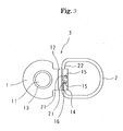
- the cover member 8 is constituted by an annular basement portion 6 provided with a window portion 61 in the center, and a cover body 7 connected to an end portion of the basement portion 6 via a connection portion 71.
- the basement portion 6 has an approximately circular board portion 62 pressing the flange 52 in a state in which the bolt head portion 51 is protruded from the window portion 61, and a peripheral wall portion 63 provided in a handing manner in an outer periphery of the board portion 62.
- the connection portion 71 is bent so as to cover the tubular portion 14 of the hook member 3.
- the cover body 7 is provided with a cover plate portion 72 covering the bolt head portion 51, and a side wall 73 provided in a rising manner around the cover plate portion. An end portion of the wide wall 73 is provided with a locking pawl 74 for locking the cover body 7 covering the bolt head portion 51 to the basement portion 6.
- the cover body 7 is formed in an outer shape dimension which is opened and closed by a hinge 75 so as to be capable of passing through an inner side of the hook 2.
- the board portion 62 is provided with a circular protuberance 64 going around the window portion 61, and a semicircular protuberance 65 formed so as to be spaced with respect to the circular protuberance 64, and a semicircular concave groove portion 66 is formed between the circular protuberance 64 and the semicircular protuberance 65.
- An end portion of the side wall 73 is fitted to the concave groove portion 66, and the concave groove portion 66 is provided with a notch portion 67 engaging with the locking pawl 74 so as to lock the cover body 7 in a closed state.
- peripheral wall portion 63 An inner side of the peripheral wall portion 63 is provided with a locking hook 68 for attaching the cover member 8 to the base plate 1, and the locking pawl 68 is locked to an outer peripheral edge of the base plate 1. Further, a notch portion 69 is provided in the peripheral wall portion 63 in a lower side of the connection portion 71, whereby the peripheral wall portion 63 does not form an obstacle to the protruding piece 12 at a time of fitting the base plate 1 to the board portion 62.
- the bolt 5 is inserted to the bolt insertion hole 11 of the base plate 1 of the hook member 3, and the flange 52 is brought into contact with the base plate 1. Further, the base plate 1 is fitted to the inner portion of the basement portion 6 so as to be locked, in a state in which the bolt head portion 51 is protruded from the window portion 61 of the basement portion 6. Accordingly, since the board portion 62 presses the flange 52, it is possible to integrally assemble the hook member 3, the bolt 5 and the cover member 8. Further, the hook attaching unit with a spacer 9 can be obtained by screwing the spacer 9 having a female thread as occasion demands.
- the bolt 5 When attaching the hook attaching unit with the spacer as mentioned above to the side surface of the room inside of the motor vehicle, the bolt 5 is inserted to a prepared hole 103 of a concave portion 101a of a first panel (a trim) 101, and a leading end thereof is screwed with a nut 105 firmly attached to a prepared hole 104 of a second panel (an inner panel) 102. Further, when carrying on the rotation of the bolt 5, the spacer 9 is seated on the second panel 102 as shown in Fig. 9, and the fastening of the attaching unit is finished.
- the locking pawl 74 is locked to the basement portion 6, and it is possible to cover the cover body 7 on the bolt head portion 51. Since a length of the spacer 9 is adjusted, the upper surface of the cover body 7 can be positioned on the same surface as a plate surface 101b of the first panel 101.
- the spacer 9 is structured, as shown in Fig. 2, such that a flat surface 91 and a circular arc surface 92 are formed in a side surface so as to be spaced, and an outer diameter of the circular arc surface 92 is set equal to an outer diameter of the short tube portion 13, the spacer 9 can easily pass through the prepared hole 103 of the first panel 101 together with the short tube portion 13.
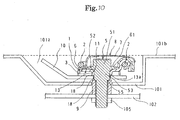
- Fig. 10 shows an embodiment in which the hook attaching unit is used for attaching the seat belt anchor 10.
- the shaft portion 53 is set to a length capable of installing the seat belt anchor plate 10, and is protruded from the end surface 13a of the short tube portion 13. Since a protruding length is set slightly longer than a thickness of the seat belt anchor plate 10, such that a play 18 is formed in upper and lower surfaces of the seat belt anchor plate 10, it is possible to flexibly tilt the seat belt anchor plate 10 at a time of installing the seat belt.
- the length of the spacer 9 is adjusted in such a manner that the upper surface of the cover body 7 is positioned on the same surface as the plate surface 101b of the first panel 101. Accordingly, as shown in Fig. 11, the cover body 7 can be attached to the first panel 101 without protruding from the concave portion 101a.
- the hook attaching unit in accordance with the present invention can be utilized for installing the seat belt anchor plate 10. Since the attachment of the hook and the attachment of the seat belt anchor plate have been conventionally achieved by the independent attaching members, the number of parts is increased and the cost is increased. However, it is possible to achieve a cost reduction on the basis of the present invention.
Abstract
Description
- The present invention relates to a hook attaching unit for attaching a hook to a room inside of a motor vehicle.
- It is often the case that a hook locking a clothes hanger, a cord of a shopping bag or the like is provided in a side surface in a room inside of a motor vehicle. As such a hook, in
Japanese Unexamined Patent Publication No. 2000-316704 - Further, since the hook and the bolt are not integrally assembled, there is a problem that a workability is deteriorated at a time of attaching the hook in a motor vehicle assembling line.
- Accordingly, an object of the present invention is to provide a hook attaching unit which has an improved outer appearance, and an excellent workability for attaching a hook.
- A hook attaching unit in accordance with the present invention carried out for achieving the object mentioned above is constituted by a hook member in which a hook is rotatably attached to an end portion of a base plate, a bolt inserted to a bolt insertion hole provided in the base plate, and a resin cover member installed to the base plate so as to prevent the bolt from coming off from the base plate and cover a bolt head portion invisibly. As mentioned above, in the hook attaching unit in accordance with the present invention, since the hook member, the cover member and the bolt are integrally assembled, it is not necessary to install the bolt point by point in a work field and install the cover member after attaching the hook, and a workability at a time of fastening is good. Further, since the cover member invisibly covers the bolt head portion, there can be obtained an effect that a safety and an improved outer appearance can be obtained.
- In accordance with a preferable embodiment, the hook is formed by bending a metal wire, and the base plate is structured such that a protruding piece made of a metal and provided in one end thereof is wound around the metal wire, and the hook is rotatably attached to the base plate. Accordingly, it is possible to rotatably attach the hook to the base plate. Further, since the hook and the base plate are made of the metal, a durability against an impact force is obtained in comparison with the resin structure. Accordingly, it is possible to install a seat belt anchor plate as mentioned below.
- In preferable, the hook is formed in a D shape, and end portions of the metal wire are faced to each other at an interval in a linear portion of the D-shaped portion, a protrusion piece is provided in a leading end of the protruding piece, and the protrusion piece is pushed into the gap so as to form a stopper inhibiting the hook from moving. Accordingly, it is possible to inhibit the hook frommoving in a horizontal direction, and it is possible to prevent the hook from injuring the cover member.
- Further, the structure may be made such that the bolt is constituted by a flange bolt, and the cover member is constituted by an annular basement portion pressing a flange in a state in which the bolt head portion is protruded from a center window portion, and a cover body flexibly connected to an end portion of the basement portion so as to release the bolt head portion at a time of fastening the bolt and cover the bolt head portion after fastening the bolt. In accordance with the structure mentioned above, it is possible to install the bolt so as to prevent the bolt from unthreading from the hook member by pressing the flange by the annular basement portion. Further, since the cover body can be released from the bolt head portion at a time of fastening the bolt, the cover body does not form an obstacle to the fastening work.
- Further, the structure may be made such that a short tube portion having an end surface is provided in a protruding manner around the bolt insertion hole of the base plate, and a stepped shaft portion protruding from the end surface at a time of being fitted into the short tube portion is provided below a neck of the bolt. Since it is possible to form a small gap between the end surface ot the short tube portion and the spacer even at a time when the spacer is installed to the bolt soas to be brought into contact with the step, it is possible to integrally rotate the bolt and the spacer without bringing the spacer into contact with the end surface. In this case, if the stepped shaft portion is protruded from the end surface of the short tube portion at a length capable of installing a seat belt anchor, it is possible to install the seat belt anchor to the short tube portion. Accordingly, it is possible to use one mounting unit in common for attaching the hook and the seat belt anchor plate, and there is an advantage that it is possible to reduce the number of parts and improve a workability.
- Further, if the bolt is provided with a spacer with a female thread for adjusting a height, it is possible to adjust the height by the spacer. Accordingly, an upper surface of the cover body neither protrudes from a panel plate surface of a vehicle body nor be positioned at the depth.
-
- Fig. 1 is a cross sectional view of a hook attaching unit;
- Fig. 2 is a perspective view of the hook attaching unit;
- Fig. 3 is a bottom elevational view of a hook member;
- Fig. 4 is a plan view of the hook member;
- Fig. 5 is a front elevational view of the hook member;
- Fig. 6 is a plan view of a cover member;
- Fig. 7 is a bottom elevational view of the cover member;
- Fig. 8 is a front elevational view of the cover member;
- Fig. 9 is a cross sectional view showing an attached state of the hook attaching unit;
- Fig. 10 is a cross sectional view of a state in which a seat belt anchor plate is installed; and
- Fig. 11 is a perspective view of a state in which the seat belt anchor plate is fixed to a concave portion of a trim.
- A description will be given below of a preferable embodiment in accordance with the present invention.
- Figs. 1 and 2 are views showing a hook attaching unit in accordance with the present invention. The unit is constituted by a
hook member 3 in which ahook 2 is rotatably attached to an end portion of abase plate 1, abolt 5 inserted to abolt insertion hole 11 provided in thebase plate 1, and aresin cover member 8 in which acover body 7 is connected to anannular basement portion 6 installed to thebase plate 1. Aspacer 9 is screwed with thebolt 5. - Figs. 3 to 5 are views showing details of the
hook member 3. Thebolt insertion hole 11 is formed in a center of the approximatelycircular base plate 1, and aprotruding piece 12 is provided in an end portion thereof. Thehook 2 is formed by bending a metal wire in a D shape, andend portions 21 of the metal wire face each other in alinear portion 22 of the D-shaped portion.Notches 15 for easily bending a leading end of the protrudingpiece 12 are formed at two positions of theprotruding piece 12. Accordingly, the leading end of theprotruding piece 12 is wound around theend portion 21 of the metal wire so as to form atubular portion 14, and thehook 2 is rotatably attached to thebase plate 1 by thetubular portion 14. Aprotrusion piece 16 is formed between thenotches 15, and theprotrusion piece 16 is folded and pressed between the facingend portions 21 of the metal wire, so as to be formed as a stopper for inhibiting thehook 2 from moving in an axial direction within thetubular portion 14. Accordingly, it is possible to prevent a damage caused by a thrust of thehook 2 with thecover member 8 from a horizontal direction. - A
short tube portion 13 is provided in a protruding manner around thebolt insertion hole 11 in such a manner as to protrude to a back side of thebase plate 1 from thebolt insertion hole 11. Theshort tube portion 13 has anend surface 13a in an end portion thereof. - The
bolt 5 has ahead portion 51 formed in a hexagonal shape and engaging with a tool, and aflange 52 peripherally provided in a lower portion of thehead portion 51, as shown in Figs. 1 and 2, and ashaft portion 53 with no thread fitted into theshort tube portion 13 with no play is formed below a neck of thebolt 5, that is, in a lower side of theflange 52. Theshaft portion 53 is formed so as to have a larger diameter than that of amale thread portion 54 of thebolt 5, and is provided with astep 55 protruding from theend surface 13a of theshort tube portion 13 at a time when theflange 52 is brought into contact with thebase plate 1. On the basis of thestep 55, since it is possible to form asmall gap 17 between theend surface 13a of theshort tube portion 13 and thespacer 9 even at a time when thespacer 9 installed to thebolt 5 is brought into contact with thestep 55, it is possible to integrally rotate thebolt 5 and thespacer 9 without bringing thespacer 9 into contact with theend surface 13a. - Details of the
cover member 8 will be shown in Figs. 6 to 8. Thecover member 8 is constituted by anannular basement portion 6 provided with awindow portion 61 in the center, and acover body 7 connected to an end portion of thebasement portion 6 via aconnection portion 71. Thebasement portion 6 has an approximatelycircular board portion 62 pressing theflange 52 in a state in which thebolt head portion 51 is protruded from thewindow portion 61, and aperipheral wall portion 63 provided in a handing manner in an outer periphery of theboard portion 62. Further, theconnection portion 71 is bent so as to cover thetubular portion 14 of thehook member 3. - The
cover body 7 is provided with acover plate portion 72 covering thebolt head portion 51, and aside wall 73 provided in a rising manner around the cover plate portion. An end portion of thewide wall 73 is provided with alocking pawl 74 for locking thecover body 7 covering thebolt head portion 51 to thebasement portion 6. Thecover body 7 is formed in an outer shape dimension which is opened and closed by ahinge 75 so as to be capable of passing through an inner side of thehook 2. Further, theboard portion 62 is provided with acircular protuberance 64 going around thewindow portion 61, and asemicircular protuberance 65 formed so as to be spaced with respect to thecircular protuberance 64, and a semicircularconcave groove portion 66 is formed between thecircular protuberance 64 and thesemicircular protuberance 65. An end portion of theside wall 73 is fitted to theconcave groove portion 66, and theconcave groove portion 66 is provided with anotch portion 67 engaging with the lockingpawl 74 so as to lock thecover body 7 in a closed state. - An inner side of the
peripheral wall portion 63 is provided with a lockinghook 68 for attaching thecover member 8 to thebase plate 1, and the lockingpawl 68 is locked to an outer peripheral edge of thebase plate 1. Further, anotch portion 69 is provided in theperipheral wall portion 63 in a lower side of theconnection portion 71, whereby theperipheral wall portion 63 does not form an obstacle to the protrudingpiece 12 at a time of fitting thebase plate 1 to theboard portion 62. - In order to assemble the hook attaching unit in accordance with the present invention, as shown in Fig. 1, the
bolt 5 is inserted to thebolt insertion hole 11 of thebase plate 1 of thehook member 3, and theflange 52 is brought into contact with thebase plate 1. Further, thebase plate 1 is fitted to the inner portion of thebasement portion 6 so as to be locked, in a state in which thebolt head portion 51 is protruded from thewindow portion 61 of thebasement portion 6. Accordingly, since theboard portion 62 presses theflange 52, it is possible to integrally assemble thehook member 3, thebolt 5 and thecover member 8. Further, the hook attaching unit with aspacer 9 can be obtained by screwing thespacer 9 having a female thread as occasion demands. - When attaching the hook attaching unit with the spacer as mentioned above to the side surface of the room inside of the motor vehicle, the
bolt 5 is inserted to aprepared hole 103 of aconcave portion 101a of a first panel (a trim) 101, and a leading end thereof is screwed with anut 105 firmly attached to aprepared hole 104 of a second panel (an inner panel) 102. Further, when carrying on the rotation of thebolt 5, thespacer 9 is seated on thesecond panel 102 as shown in Fig. 9, and the fastening of the attaching unit is finished. Thereafter, if thecover body 7 is weighed down in a direction of thebolt head portion 51, the lockingpawl 74 is locked to thebasement portion 6, and it is possible to cover thecover body 7 on thebolt head portion 51. Since a length of thespacer 9 is adjusted, the upper surface of thecover body 7 can be positioned on the same surface as aplate surface 101b of thefirst panel 101. - Since the
spacer 9 is structured, as shown in Fig. 2, such that aflat surface 91 and acircular arc surface 92 are formed in a side surface so as to be spaced, and an outer diameter of thecircular arc surface 92 is set equal to an outer diameter of theshort tube portion 13, thespacer 9 can easily pass through theprepared hole 103 of thefirst panel 101 together with theshort tube portion 13. - In this case, it is possible to accommodate the
hook 2 by rotating thehook 2 to an upper side of thebasement portion 6 as shown in Fig. 9 at a time when thehook 2 is not used. When thehook 2 is used, thehook 2 is used by rotating so as to detach from thebasement portion 6. - Fig. 10 shows an embodiment in which the hook attaching unit is used for attaching the
seat belt anchor 10. In this embodiment, theshaft portion 53 is set to a length capable of installing the seatbelt anchor plate 10, and is protruded from theend surface 13a of theshort tube portion 13. Since a protruding length is set slightly longer than a thickness of the seatbelt anchor plate 10, such that aplay 18 is formed in upper and lower surfaces of the seatbelt anchor plate 10, it is possible to flexibly tilt the seatbelt anchor plate 10 at a time of installing the seat belt. - Even in this case, the length of the
spacer 9 is adjusted in such a manner that the upper surface of thecover body 7 is positioned on the same surface as theplate surface 101b of thefirst panel 101. Accordingly, as shown in Fig. 11, thecover body 7 can be attached to thefirst panel 101 without protruding from theconcave portion 101a. - As mentioned above, the hook attaching unit in accordance with the present invention can be utilized for installing the seat
belt anchor plate 10. Since the attachment of the hook and the attachment of the seat belt anchor plate have been conventionally achieved by the independent attaching members, the number of parts is increased and the cost is increased. However, it is possible to achieve a cost reduction on the basis of the present invention.
Claims (7)
- A hook attaching unit comprising:a hook member in which a hook is rotatably attached to an end portion of a base plate;a bolt inserted to a bolt insertion hole provided in the base plate; anda resin cover member installed to the base plate so as to prevent the bolt from coming off from the base plate and cover a bolt head portion invisibly.
- The hook attaching unit as claimed in claim 1, wherein the hook is formed by bending a metal wire, and the base plate is structured such that a protruding piece made of a metal and provided in one end thereof is wound around the metal wire, and the hook is rotatably attached to the base plate.
- The hook attaching unit as claimed in claim 2, wherein the hook is formed in a D shape, and end portions of the metal wire are faced to each other at an interval in a linear portion of the D-shaped portion, a protrusion piece is provided in a leading end of the protruding piece, and the protrusion piece is pushed into the gap so as to form a stopper for inhibiting the hook from moving.
- The hook attaching unit as claimed in claim 1, wherein the bolt is constituted by a flange bolt, and the cover member is constituted by an annular basement portion pressing a flange in a state in which the bolt head portion is protruded from a center window portion, and a cover body flexibly connected to an end portion of the basement portion so as to release the bolt head portion at a time of fastening the bolt and cover the bolt head portion after fastening the bolt.
- The hook attaching unit as claimed in claim 1, wherein a short tube portion having an end surface is provided in a protruding manner around the bolt insertion hole of the base plate, and a stepped shaft portion protruding from the end surface at a time of being fitted into the short tube portion is provided below a neck of the bolt.
- The hook attaching unit as claimed in claim 5, wherein the stepped shaft portion is protruded from the end surface of the short tube portion at a length capable of installing a seat belt anchor.
- The hook attaching unit as claimed in claim 1, wherein the bolt is provided with a spacer with a female thread for adjusting a height.
Applications Claiming Priority (1)
| Application Number | Priority Date | Filing Date | Title |
|---|---|---|---|
| JP2005320926A JP2007125233A (en) | 2005-11-04 | 2005-11-04 | Hook mounting unit |
Publications (2)
| Publication Number | Publication Date |
|---|---|
| EP1783013A2 true EP1783013A2 (en) | 2007-05-09 |
| EP1783013A3 EP1783013A3 (en) | 2009-09-09 |
Family
ID=37701724
Family Applications (1)
| Application Number | Title | Priority Date | Filing Date |
|---|---|---|---|
| EP20060255655 Withdrawn EP1783013A3 (en) | 2005-11-04 | 2006-11-02 | Hook or ring attaching unit |
Country Status (4)
| Country | Link |
|---|---|
| US (1) | US7780384B2 (en) |
| EP (1) | EP1783013A3 (en) |
| JP (1) | JP2007125233A (en) |
| CN (1) | CN1966309B (en) |
Families Citing this family (19)
| Publication number | Priority date | Publication date | Assignee | Title |
|---|---|---|---|---|
| WO2008105647A1 (en) * | 2007-02-26 | 2008-09-04 | Power Retailing Group, S.A. De C.V. | Easy-to-dismantle display packaging |
| JP5374859B2 (en) * | 2007-11-07 | 2013-12-25 | トヨタ紡織株式会社 | Locking structure of hook member and skin material |
| JP5243304B2 (en) * | 2008-04-10 | 2013-07-24 | 株式会社ニフコ | Article fixing tool |
| JP5200958B2 (en) * | 2009-01-27 | 2013-06-05 | トヨタ紡織株式会社 | clip |
| JP2011051486A (en) * | 2009-09-02 | 2011-03-17 | Honda Motor Co Ltd | Tie-down hook mounting structure |
| GB2488137B (en) * | 2011-02-17 | 2015-10-07 | Bentley Motors Ltd | Mounting structure |
| JP2012233532A (en) * | 2011-04-28 | 2012-11-29 | Nifco Inc | Bolt cap fastening structure |
| ES2400428B1 (en) * | 2011-08-05 | 2014-02-28 | Illinois Toll Works Inc. | LOAD RING |
| JP6279103B2 (en) * | 2014-12-24 | 2018-02-14 | 株式会社パイオラックス | Holding device |
| CN106585505A (en) * | 2015-10-20 | 2017-04-26 | 福特环球技术公司 | Object plugging assembly capable of being used on vehicle |
| CN107327052A (en) * | 2017-05-25 | 2017-11-07 | 广东坚朗五金制品股份有限公司 | Articulated mounting and the fixture with the articulated mounting |
| JP6999082B2 (en) * | 2017-10-31 | 2022-01-18 | 川崎車両株式会社 | Underfloor duct |
| CN108099837A (en) * | 2017-12-26 | 2018-06-01 | 江铃汽车股份有限公司 | Seat-belt anchorage and vehicle |
| CN108973809A (en) * | 2018-06-25 | 2018-12-11 | 上海汽车集团股份有限公司 | Multifunctional interface device after motor vehicle seat back |
| US10927977B2 (en) * | 2018-08-28 | 2021-02-23 | Ofs Fitel, Llc | Concealed safety fasteners for communication lines |
| JP7153927B2 (en) * | 2019-03-01 | 2022-10-17 | 株式会社ピカコーポレイション | hook tool |
| KR102320380B1 (en) * | 2020-02-18 | 2021-11-03 | 아우토리브 디벨롭먼트 아베 | Apparatus for seat belt installation |
| US11879495B2 (en) * | 2021-02-02 | 2024-01-23 | Wei-Chih Chen | Thermally insulating fixture |
| CN113978373A (en) * | 2021-08-31 | 2022-01-28 | 北京长安汽车工程技术研究有限责任公司 | Hidden couple |
Citations (4)
| Publication number | Priority date | Publication date | Assignee | Title |
|---|---|---|---|---|
| JPH06115407A (en) * | 1992-10-09 | 1994-04-26 | Suzuki Motor Corp | Seat belt guiding device |
| JPH075988U (en) * | 1993-06-23 | 1995-01-27 | 株式会社東郷製作所 | Slip joint for seat belt |
| US5476286A (en) | 1994-10-21 | 1995-12-19 | Delfino; Nicholas A. | Extension bracket for attaching a seat-belt guide |
| JP2000316704A (en) | 1999-05-13 | 2000-11-21 | Kanto Auto Works Ltd | Removable hook |
Family Cites Families (9)
| Publication number | Priority date | Publication date | Assignee | Title |
|---|---|---|---|---|
| GB190628787A (en) * | 1906-12-17 | 1907-12-17 | Joseph Andre Fresco | |
| JPH0435036U (en) * | 1990-07-14 | 1992-03-24 | ||
| JPH07329709A (en) * | 1994-06-08 | 1995-12-19 | Nippon Seiko Kk | Mounting device for waving |
| CN2209734Y (en) * | 1994-10-01 | 1995-10-11 | 应远信 | Integral plastic hook |
| JP3489274B2 (en) * | 1995-06-28 | 2004-01-19 | スズキ株式会社 | Mounting structure of tether anchor bracket for child seat |
| US6209179B1 (en) | 1999-09-16 | 2001-04-03 | Chen Shou-Mao | Clasping device |
| US6213696B1 (en) * | 2000-02-22 | 2001-04-10 | M & C Corporation | Cargo restraint device |
| JP4147929B2 (en) * | 2002-12-17 | 2008-09-10 | トヨタ自動車株式会社 | Seat belt wrap outer anchor mounting structure |
| DE102004061087B4 (en) | 2004-12-18 | 2006-12-07 | A. Raymond Et Cie | Device for attaching an attachment and a support member at a distance from each other |
-
2005
- 2005-11-04 JP JP2005320926A patent/JP2007125233A/en active Pending
-
2006
- 2006-10-25 US US11/552,569 patent/US7780384B2/en active Active
- 2006-11-02 EP EP20060255655 patent/EP1783013A3/en not_active Withdrawn
- 2006-11-02 CN CN2006101433848A patent/CN1966309B/en active Active
Patent Citations (4)
| Publication number | Priority date | Publication date | Assignee | Title |
|---|---|---|---|---|
| JPH06115407A (en) * | 1992-10-09 | 1994-04-26 | Suzuki Motor Corp | Seat belt guiding device |
| JPH075988U (en) * | 1993-06-23 | 1995-01-27 | 株式会社東郷製作所 | Slip joint for seat belt |
| US5476286A (en) | 1994-10-21 | 1995-12-19 | Delfino; Nicholas A. | Extension bracket for attaching a seat-belt guide |
| JP2000316704A (en) | 1999-05-13 | 2000-11-21 | Kanto Auto Works Ltd | Removable hook |
Also Published As
| Publication number | Publication date |
|---|---|
| CN1966309A (en) | 2007-05-23 |
| JP2007125233A (en) | 2007-05-24 |
| CN1966309B (en) | 2011-11-23 |
| EP1783013A3 (en) | 2009-09-09 |
| US7780384B2 (en) | 2010-08-24 |
| US20070102610A1 (en) | 2007-05-10 |
Similar Documents
| Publication | Publication Date | Title |
|---|---|---|
| EP1783013A2 (en) | Hook or ring attaching unit | |
| CA2430170C (en) | Handrail and end member assembly | |
| US5377450A (en) | Adjustable door handle assembly | |
| JPH0452486Y2 (en) | ||
| JPS5934732Y2 (en) | Parts mounting structure | |
| US5884434A (en) | Door handle to latch rod connection | |
| AU2002235393A1 (en) | Handrail and end member assembly | |
| US5031953A (en) | Visor bracket | |
| US20050241121A1 (en) | Fastener | |
| US6836932B2 (en) | Assist grip | |
| US6216992B1 (en) | Mounting device for securing a sink to a countertop and method of using same | |
| US6735824B2 (en) | Accessory mounting mechanism | |
| US8376425B2 (en) | Automotive door striker | |
| US20020124606A1 (en) | Cylinder lock mounting device | |
| US6386518B1 (en) | Handrail and end member assembly | |
| JP2003516262A (en) | Fluid device with fixed accessory | |
| KR100628497B1 (en) | Supporting structure for double floor | |
| US8052189B2 (en) | Trim ring having reinforced snap posts | |
| JP3239687B2 (en) | Molding protector for wire harness | |
| JP3280996B2 (en) | Automotive door mirror mounting structure | |
| JP3571964B2 (en) | Mounting bracket for exterior material | |
| US5201157A (en) | Pole top cover expandable bracket assembly | |
| JP4580723B2 (en) | handrail | |
| JP2003267131A (en) | Structure of provisionally holding part of door mirror base assembly | |
| KR0163083B1 (en) | Inside handle housing establish structure of vehicle door |
Legal Events
| Date | Code | Title | Description |
|---|---|---|---|
| PUAI | Public reference made under article 153(3) epc to a published international application that has entered the european phase |
Free format text: ORIGINAL CODE: 0009012 |
|
| AK | Designated contracting states |
Kind code of ref document: A2 Designated state(s): AT BE BG CH CY CZ DE DK EE ES FI FR GB GR HU IE IS IT LI LT LU LV MC NL PL PT RO SE SI SK TR |
|
| AX | Request for extension of the european patent |
Extension state: AL BA HR MK YU |
|
| PUAL | Search report despatched |
Free format text: ORIGINAL CODE: 0009013 |
|
| AK | Designated contracting states |
Kind code of ref document: A3 Designated state(s): AT BE BG CH CY CZ DE DK EE ES FI FR GB GR HU IE IS IT LI LT LU LV MC NL PL PT RO SE SI SK TR |
|
| AX | Request for extension of the european patent |
Extension state: AL BA HR MK RS |
|
| RIC1 | Information provided on ipc code assigned before grant |
Ipc: B60R 7/10 20060101ALI20090803BHEP Ipc: F16B 45/00 20060101ALI20090803BHEP Ipc: F16B 41/00 20060101ALI20090803BHEP Ipc: B60R 22/18 20060101AFI20070213BHEP |
|
| 17P | Request for examination filed |
Effective date: 20100113 |
|
| 17Q | First examination report despatched |
Effective date: 20100219 |
|
| AKX | Designation fees paid |
Designated state(s): CZ DE FR GB TR |
|
| STAA | Information on the status of an ep patent application or granted ep patent |
Free format text: STATUS: THE APPLICATION IS DEEMED TO BE WITHDRAWN |
|
| 18D | Application deemed to be withdrawn |
Effective date: 20150707 |