EP1781924B1 - A linear free piston stirling machine - Google Patents
A linear free piston stirling machine Download PDFInfo
- Publication number
- EP1781924B1 EP1781924B1 EP05768092A EP05768092A EP1781924B1 EP 1781924 B1 EP1781924 B1 EP 1781924B1 EP 05768092 A EP05768092 A EP 05768092A EP 05768092 A EP05768092 A EP 05768092A EP 1781924 B1 EP1781924 B1 EP 1781924B1
- Authority
- EP
- European Patent Office
- Prior art keywords
- power piston
- piston
- resilient member
- contact
- machine
- Prior art date
- Legal status (The legal status is an assumption and is not a legal conclusion. Google has not performed a legal analysis and makes no representation as to the accuracy of the status listed.)
- Expired - Lifetime
Links
Images
Classifications
-
- F—MECHANICAL ENGINEERING; LIGHTING; HEATING; WEAPONS; BLASTING
- F02—COMBUSTION ENGINES; HOT-GAS OR COMBUSTION-PRODUCT ENGINE PLANTS
- F02G—HOT GAS OR COMBUSTION-PRODUCT POSITIVE-DISPLACEMENT ENGINE PLANTS; USE OF WASTE HEAT OF COMBUSTION ENGINES; NOT OTHERWISE PROVIDED FOR
- F02G1/00—Hot gas positive-displacement engine plants
- F02G1/04—Hot gas positive-displacement engine plants of closed-cycle type
- F02G1/043—Hot gas positive-displacement engine plants of closed-cycle type the engine being operated by expansion and contraction of a mass of working gas which is heated and cooled in one of a plurality of constantly communicating expansible chambers, e.g. Stirling cycle type engines
- F02G1/0435—Hot gas positive-displacement engine plants of closed-cycle type the engine being operated by expansion and contraction of a mass of working gas which is heated and cooled in one of a plurality of constantly communicating expansible chambers, e.g. Stirling cycle type engines the engine being of the free piston type
-
- F—MECHANICAL ENGINEERING; LIGHTING; HEATING; WEAPONS; BLASTING
- F02—COMBUSTION ENGINES; HOT-GAS OR COMBUSTION-PRODUCT ENGINE PLANTS
- F02G—HOT GAS OR COMBUSTION-PRODUCT POSITIVE-DISPLACEMENT ENGINE PLANTS; USE OF WASTE HEAT OF COMBUSTION ENGINES; NOT OTHERWISE PROVIDED FOR
- F02G2275/00—Controls
- F02G2275/20—Controls for preventing piston over stroke
-
- F—MECHANICAL ENGINEERING; LIGHTING; HEATING; WEAPONS; BLASTING
- F02—COMBUSTION ENGINES; HOT-GAS OR COMBUSTION-PRODUCT ENGINE PLANTS
- F02G—HOT GAS OR COMBUSTION-PRODUCT POSITIVE-DISPLACEMENT ENGINE PLANTS; USE OF WASTE HEAT OF COMBUSTION ENGINES; NOT OTHERWISE PROVIDED FOR
- F02G2280/00—Output delivery
- F02G2280/10—Linear generators
Definitions
- the present invention relates to a linear free piston Stirling machine.
- a machine may be an engine, for example, for use in a domestic combined heat and power system, or may be a cooler for a refrigerating system.
- the displacer and power piston within the free piston machine are tuned as a mechanical spring-mass-damper resonators which reciprocate independently.
- a flexible rod the lower end of which is fastened to a planar spring located in a lower dome of the machine, passes through the centre of the piston and is connected to the lower part of the displacer.
- a further alternative is to use a gas spring as shown in DE 1 953 8422 and JP 4047150 to provide a cushioning effect.
- these reduce the efficiency of the engine as, in order to exert sufficient force to prevent collisions, the gas spring forces must start to act at a point where overstroke is not a risk. This unnecessary expenditure of energy will reduce the efficiency of the design.
- a linear free piston Stirling machine comprising a displacer and a power piston which are reciprocally mounted within a casing; an alternator electromagnetically coupled, in use, with the power piston; and an overstroke prevention mechanism which is fixed with respect to the casing and which comprises at least one resilient member, wherein the power piston comes into contact with the overstroke prevention mechanism when its displacement exceeds a predetermined level.
- an overstroke prevention mechanism in the form of a resilient member mounted to the casing, there is no increase in the reciprocating mass. Further, by positioning the mechanism so that the piston comes into contact with the mechanism when its displacement exceeds a predetermined level no power loss is caused during normal operation.
- the resilient member is able to have a significant effect over its short range of motion, it therefore does not need to begin to operate in the normal operation region as in the case of the gas spring.
- the overstroke prevention mechanism can be used only to prevent overstroking in one direction as this may be sufficient in certain circumstances, or it is possible to use some different overstroke prevention mechanisms to prevent overstroking in the opposite direction.
- the power piston comes into contact with the overstroke prevention mechanism when its displacement exceeds a predetermined level in either direction of reciprocation of the power piston. Such an arrangement can prevent overstroking in either direction.
- the overstroke prevention mechanism comprises a resilient member, wherein the power piston is provided with a first portion which is arranged to contact the resilient member if the displacement of the power piston exceeds the predetermined level in a first direction, and a second portion which is arranged to contact the resilient member if the displacement of the power piston exceeds the predetermined level in a second direction.
- the single resilient member or a single group of resilient members prevent overstroking in both directions. This may be achieved either by providing the first and second portions in a recess within the power piston, or alternatively, providing the first and second portions on a separate component which projects from the power piston.
- the overstroke prevention mechanism may comprise a first resilient member which is arranged to contact the power piston if the displacement of the power piston exceeds the predetermined level in a first direction and a second resilient member which is arranged to contact the power piston if the displacement of the power piston exceeds the predetermined level in a second direction.
- Such a mechanism is more complex than the mechanism referred to above for the single resilient member or group of resilient members. However, there may be circumstances under which this would be the preferred option.
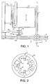
- a displacer piston (not shown) is connected to a flexible rod 1 as shown in Figure 1 which extends along the axis 2 of the machine.
- the machine is generally symmetrical about axis 2, although the right hand side is not shown in Figure 1 .
- the flexible rod 1 is connected at its lower end to a pair of planar springs 3 which provide a restoring force to the displacer.
- the rod 1 extends through the centre of power piston 4, the left-hand portion of which is shown in Figure 1 .
- the magnet drum 5 to which magnets 6 are attached is attached to reciprocate with the power piston.
- the magnets 6 reciprocate in the gap 7 within the alternator pack 8 which is fixed with respect to the machine housing.
- the overstroke mechanism is a resilient member 10 which is shown in detail in Figure 2 .
- This has an annular configuration and has a number of mounting holes 11 for mounting to the machine casing.
- a number of resilient tongues 12 project radially inwardly and are provided with holes 13.
- a spring contact peg 14 projects through each of these holes 13.
- the spring contact peg 14 is provided with a lower flange 15 and an upper flange 16.
- a number of further resilient tongues 17 are provided between the resilient tongues 12 these provide extreme one way stops.
- Four spring contact pegs 14 are contemplated and this is the optimum number. However, this example could be made to work with only two pegs positioned on opposite sides of the resilient member 10 so long as the power piston was correctly aligned. This example would also work reasonably with three spring contact pegs 14 spaced at 120° intervals.
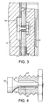
- FIG. 3 and 4 An alternative arrangement is shown in Figures 3 and 4 .
- the section has been taken from the right-hand side of the machine in that the piston 4 is within the alternator 8.
- the spring contact peg and resilient tongue arrangement of Figure 1 has been replaced by a recess 20 in the piston 4 which extends in an axial direction and a spring plug 21.
- Figure 3 where the spring plug 21 is mounted in the alternator 8 it projects into the groove 20.
- the spring plug is shown in greater detail in Figure 4 which shows the spring plug having an enlarged head 22, a tapered portion 23 and a thinner stem 24 which provides the resilience.
- the stem 24 is a heavy press-fit into a fixing bolt 25 which is screwed into the cylinder wall 26.
- Another identical arrangement is provided at the opposite side of the machine.
Landscapes
- Engineering & Computer Science (AREA)
- Chemical & Material Sciences (AREA)
- Combustion & Propulsion (AREA)
- Mechanical Engineering (AREA)
- General Engineering & Computer Science (AREA)
- Connection Of Motors, Electrical Generators, Mechanical Devices, And The Like (AREA)
- Compressors, Vaccum Pumps And Other Relevant Systems (AREA)
- Pistons, Piston Rings, And Cylinders (AREA)
- Emergency Lowering Means (AREA)
- Devices That Are Associated With Refrigeration Equipment (AREA)
Abstract
Description
- The present invention relates to a linear free piston Stirling machine. Such a machine may be an engine, for example, for use in a domestic combined heat and power system, or may be a cooler for a refrigerating system.
- The displacer and power piston within the free piston machine are tuned as a mechanical spring-mass-damper resonators which reciprocate independently. A flexible rod, the lower end of which is fastened to a planar spring located in a lower dome of the machine, passes through the centre of the piston and is connected to the lower part of the displacer.
- As the piston reciprocates in the Stirling engine, a magnet drum connected to this piston moves through coils of an alternator, so generating electricity.
- Various approaches have been adopted in order to maintain the amplitude of reciprocation of the power piston within the physical limit of the design and avoid collisions at the end of each stroke. For example, two rows of secondary magnets have been incorporated on the magnet drum, in addition to the main field magnet as described in
US 5,148,066 . The secondary magnets produce a magnetic spring which keeps the amplitude of reciprocation within the required limits. However, the inclusion of the magnets reduces the efficiency of the system due to a reduction in the density of magnetic flux produced by the field magnets, caused by fringing fields extending above and below the spring magnets. - An alternative approach adopted in
GB 2136087 - A further alternative is to use a gas spring as shown in
DE 1 953 8422 andJP 4047150 - Providing a cushioning effect with two resilient members is known from
US 3782839 orJP 58210379 - It is an object of the present invention to provide an overstroke prevention mechanism which does not increase the mass to be reciprocated and which also does not cause parasitic power loss when the engine is reciprocated within normal limits.
- According to the present invention, there is provided a linear free piston Stirling machine comprising a displacer and a power piston which are reciprocally mounted within a casing; an alternator electromagnetically coupled, in use, with the power piston; and an overstroke prevention mechanism which is fixed with respect to the casing and which comprises at least one resilient member, wherein the power piston comes into contact with the overstroke prevention mechanism when its displacement exceeds a predetermined level.
- By providing an overstroke prevention mechanism in the form of a resilient member mounted to the casing, there is no increase in the reciprocating mass. Further, by positioning the mechanism so that the piston comes into contact with the mechanism when its displacement exceeds a predetermined level no power loss is caused during normal operation. The resilient member is able to have a significant effect over its short range of motion, it therefore does not need to begin to operate in the normal operation region as in the case of the gas spring.
- In the broadest sense, the overstroke prevention mechanism can be used only to prevent overstroking in one direction as this may be sufficient in certain circumstances, or it is possible to use some different overstroke prevention mechanisms to prevent overstroking in the opposite direction. However, preferably, the power piston comes into contact with the overstroke prevention mechanism when its displacement exceeds a predetermined level in either direction of reciprocation of the power piston. Such an arrangement can prevent overstroking in either direction.
- One way of implementing this is for the overstroke prevention mechanism to comprise a resilient member, wherein the power piston is provided with a first portion which is arranged to contact the resilient member if the displacement of the power piston exceeds the predetermined level in a first direction, and a second portion which is arranged to contact the resilient member if the displacement of the power piston exceeds the predetermined level in a second direction. Effectively, the single resilient member or a single group of resilient members prevent overstroking in both directions. This may be achieved either by providing the first and second portions in a recess within the power piston, or alternatively, providing the first and second portions on a separate component which projects from the power piston.
- Alternatively, the overstroke prevention mechanism may comprise a first resilient member which is arranged to contact the power piston if the displacement of the power piston exceeds the predetermined level in a first direction and a second resilient member which is arranged to contact the power piston if the displacement of the power piston exceeds the predetermined level in a second direction. This effectively provides different resilient members to prevent overstroking in the two directions. Such a mechanism is more complex than the mechanism referred to above for the single resilient member or group of resilient members. However, there may be circumstances under which this would be the preferred option.
- Examples of Stirling machines in accordance with the present invention will now be described with reference to the accompanying drawings, in which:-
-
Figure 1 is a schematic view of the various components in the base of the Stirling machine (left hand side only) ; -
Figure 2 is a plan of the resilient member ofFigure 1 ; -
Figure 3 shows a portion of the Stirling engine incorporating a second example of a resilient mechanism; and -
Figure 4 is a schematic view of the resilient mechanism ofFigure 3 in greater detail. - The structure and operation of a linear free piston Stirling machine is well-known in the art and will not be described in detail here,
- As is well-known, a displacer piston (not shown) is connected to a flexible rod 1 as shown in
Figure 1 which extends along the axis 2 of the machine. The machine is generally symmetrical about axis 2, although the right hand side is not shown inFigure 1 . The flexible rod 1 is connected at its lower end to a pair ofplanar springs 3 which provide a restoring force to the displacer. The rod 1 extends through the centre of power piston 4, the left-hand portion of which is shown inFigure 1 . Themagnet drum 5 to whichmagnets 6 are attached is attached to reciprocate with the power piston. Themagnets 6 reciprocate in the gap 7 within thealternator pack 8 which is fixed with respect to the machine housing. - The overstroke mechanism is a
resilient member 10 which is shown in detail inFigure 2 . This has an annular configuration and has a number of mounting holes 11 for mounting to the machine casing. A number ofresilient tongues 12 project radially inwardly and are provided withholes 13. As shown inFigure 1 , a spring contact peg 14 projects through each of theseholes 13. Thespring contact peg 14 is provided with alower flange 15 and anupper flange 16. As shown inFigure 2 a number of furtherresilient tongues 17 are provided between theresilient tongues 12 these provide extreme one way stops. Fourspring contact pegs 14 are contemplated and this is the optimum number. However, this example could be made to work with only two pegs positioned on opposite sides of theresilient member 10 so long as the power piston was correctly aligned. This example would also work reasonably with three spring contact pegs 14 spaced at 120° intervals. - When the power piston 4 exceeds its normal travel in an upward direction, the
lower flanges 15 of each tongue will come into contact with theresilient tongues 12 which will immediately apply a retarding force on the power piston. Similarly, if the power piston 4 exceeds its normal motion in the downward direction, theupward flanges 16 will contact theresilient tongues 12 and again apply a retarding force. Should the power piston 4 further exceed its normal travel, the bottom of the power piston will strike the furtherresilient tongues 17 providing a further increase in the retarding force. - An alternative arrangement is shown in
Figures 3 and 4 . In this case, the section has been taken from the right-hand side of the machine in that the piston 4 is within thealternator 8. The spring contact peg and resilient tongue arrangement ofFigure 1 has been replaced by arecess 20 in the piston 4 which extends in an axial direction and aspring plug 21. As shown inFigure 3 , where thespring plug 21 is mounted in thealternator 8 it projects into thegroove 20. The spring plug is shown in greater detail inFigure 4 which shows the spring plug having an enlargedhead 22, atapered portion 23 and athinner stem 24 which provides the resilience. Thestem 24 is a heavy press-fit into afixing bolt 25 which is screwed into thecylinder wall 26. Another identical arrangement is provided at the opposite side of the machine. - If the piston 4 exceeds its allowed displacement in either direction, the
spring plug 21 will contact the ends of thegroove 20 and will apply a retarding force,
Claims (3)
- A linear free piston Stirling machine comprising a displace and a power piston (4) which are reciprocably mounted within a casing; an alternator electromagnetically coupled, in use, with the power piston; and an overstroke prevention mechanism which is fixed with respect to the casing and which comprises at least one resilient member (10) wherein the power piston (4) is provided with a first portion (15) which is arranged to contact the resilient member (10) if the displacement of the power piston (4) exceeds the predetermined level in a first direction, characterised in that the power piston is provided with a second portion (16) which is arranged to contact the same resilient member (10) if the displacement of the power piston exceeds the predetermined level in a second direction.
- A machine according to claim 1, wherein the first and second portions (15,16) are provided in a recess within the power piston (4).
- A machine according to claim 1, wherein the first and second portions (15,16) are on a separate component which projects from the power piston (4).
Applications Claiming Priority (2)
| Application Number | Priority Date | Filing Date | Title |
|---|---|---|---|
| GBGB0417610.3A GB0417610D0 (en) | 2004-08-06 | 2004-08-06 | A linear free piston stirling machine |
| PCT/GB2005/003075 WO2006013380A1 (en) | 2004-08-06 | 2005-08-04 | A linear free piston stirling machine |
Publications (2)
| Publication Number | Publication Date |
|---|---|
| EP1781924A1 EP1781924A1 (en) | 2007-05-09 |
| EP1781924B1 true EP1781924B1 (en) | 2010-11-10 |
Family
ID=32982682
Family Applications (1)
| Application Number | Title | Priority Date | Filing Date |
|---|---|---|---|
| EP05768092A Expired - Lifetime EP1781924B1 (en) | 2004-08-06 | 2005-08-04 | A linear free piston stirling machine |
Country Status (7)
| Country | Link |
|---|---|
| US (1) | US7584612B2 (en) |
| EP (1) | EP1781924B1 (en) |
| JP (1) | JP2008509322A (en) |
| AT (1) | ATE487867T1 (en) |
| DE (1) | DE602005024695D1 (en) |
| GB (1) | GB0417610D0 (en) |
| WO (1) | WO2006013380A1 (en) |
Families Citing this family (4)
| Publication number | Priority date | Publication date | Assignee | Title |
|---|---|---|---|---|
| CN102667248B (en) * | 2009-10-28 | 2016-03-02 | 全球制冷有限公司 | Stirling machine with a drive reciprocating piston connected to a converter |
| CN111608819B (en) * | 2019-02-25 | 2022-07-22 | 中国科学院理化技术研究所 | A Stirling heat engine |
| US11209192B2 (en) * | 2019-07-29 | 2021-12-28 | Cryo Tech Ltd. | Cryogenic Stirling refrigerator with a pneumatic expander |
| CN111691925B (en) * | 2020-06-24 | 2021-11-09 | 张谭伟 | Air engine |
Family Cites Families (16)
| Publication number | Priority date | Publication date | Assignee | Title |
|---|---|---|---|---|
| US3782859A (en) * | 1971-12-07 | 1974-01-01 | M Schuman | Free piston apparatus |
| US4397155A (en) * | 1980-06-25 | 1983-08-09 | National Research Development Corporation | Stirling cycle machines |
| GB2114673B (en) | 1982-02-12 | 1986-01-22 | Nat Res Dev | Improvements in or relating to free piston heat engines |
| JPS58210379A (en) | 1982-05-29 | 1983-12-07 | Matsushita Electric Ind Co Ltd | Reciprocating compressor driven by a heat engine |
| US4475346A (en) * | 1982-12-06 | 1984-10-09 | Helix Technology Corporation | Refrigeration system with linear motor trimming of displacer movement |
| GB2136087B (en) | 1983-03-08 | 1986-08-20 | Atomic Energy Authority Uk | Annular spring |
| JPH0447150A (en) | 1990-06-14 | 1992-02-17 | Mitsubishi Electric Corp | Free-piston stirling engine |
| US5593991A (en) * | 1993-07-16 | 1997-01-14 | Adams; Jerry L. | Imidazole compounds, use and process of making |
| DE19538422A1 (en) | 1995-10-16 | 1997-04-17 | Krauch Helmut Prof Dr | Controlling output of Stirling-type thermal engine |
| US5693991A (en) * | 1996-02-09 | 1997-12-02 | Medis El Ltd. | Synchronous twin reciprocating piston apparatus |
| US6050092A (en) * | 1998-08-28 | 2000-04-18 | Stirling Technology Company | Stirling cycle generator control system and method for regulating displacement amplitude of moving members |
| US6199381B1 (en) | 1999-09-02 | 2001-03-13 | Sunpower, Inc. | DC centering of free piston machine |
| JP3866974B2 (en) | 2001-06-19 | 2007-01-10 | シャープ株式会社 | Stirling agency |
| JP3865679B2 (en) | 2002-01-08 | 2007-01-10 | シャープ株式会社 | Stirling refrigerator |
| EP1467159A4 (en) | 2001-12-26 | 2006-06-07 | Sharp Kk | Stirling engine |
| GB0428057D0 (en) | 2004-12-22 | 2005-01-26 | Microgen Energy Ltd | A linear free piston stirling machine |
-
2004
- 2004-08-06 GB GBGB0417610.3A patent/GB0417610D0/en not_active Ceased
-
2005
- 2005-08-04 US US11/659,529 patent/US7584612B2/en not_active Expired - Fee Related
- 2005-08-04 JP JP2007524400A patent/JP2008509322A/en active Pending
- 2005-08-04 WO PCT/GB2005/003075 patent/WO2006013380A1/en not_active Ceased
- 2005-08-04 AT AT05768092T patent/ATE487867T1/en not_active IP Right Cessation
- 2005-08-04 EP EP05768092A patent/EP1781924B1/en not_active Expired - Lifetime
- 2005-08-04 DE DE602005024695T patent/DE602005024695D1/en not_active Expired - Lifetime
Also Published As
| Publication number | Publication date |
|---|---|
| DE602005024695D1 (en) | 2010-12-23 |
| ATE487867T1 (en) | 2010-11-15 |
| EP1781924A1 (en) | 2007-05-09 |
| GB0417610D0 (en) | 2004-09-08 |
| US7584612B2 (en) | 2009-09-08 |
| US20080047265A1 (en) | 2008-02-28 |
| WO2006013380A1 (en) | 2006-02-09 |
| JP2008509322A (en) | 2008-03-27 |
Similar Documents
| Publication | Publication Date | Title |
|---|---|---|
| KR100320093B1 (en) | Adaptive interlocking fluid bearing to adjust the center of reciprocating body | |
| EP1347252B1 (en) | Stirling refrigerating machine | |
| JP2002011676A (en) | Hand-held tool device with electromagnetic impact mechanism | |
| US20090094977A1 (en) | Linear free piston stirling machine | |
| US20040061384A1 (en) | Linear electric machine | |
| US8310113B2 (en) | Multiple armature linear motor/alternator having magnetic spring with no fringe fields and increased power output | |
| US20050129540A1 (en) | Constructive arrangement for a resonant compressor | |
| CN217282522U (en) | Linear motor for Stirling refrigerator | |
| US7584612B2 (en) | Linear free piston Stirling machine | |
| JP2013135566A (en) | Vibration power generator | |
| US7827789B2 (en) | Linear free piston stirling machine | |
| KR20040023918A (en) | Linear Reciprocating Flux Reversal PM Machine | |
| KR100273431B1 (en) | Motor Core Fixed Structure of Linear Compressor | |
| JP2006296161A (en) | Linear actuator | |
| KR100246428B1 (en) | Structure for fixing inner-lamination of linear motor | |
| KR200367248Y1 (en) | Mover for linear motor | |
| JP5742860B2 (en) | Vibration generator | |
| JP2867414B2 (en) | Linear generator | |
| JP2005147094A (en) | Stirling agency | |
| KR20090064999A (en) | Reciprocating device | |
| KR100253214B1 (en) | Linear motor structure of the compressor | |
| US20250385583A1 (en) | Vibration Motor | |
| KR101240455B1 (en) | The linear vibrating motor | |
| US20110012366A1 (en) | Stirling Machine | |
| KR101171122B1 (en) | Body cover for linear compressor |
Legal Events
| Date | Code | Title | Description |
|---|---|---|---|
| PUAI | Public reference made under article 153(3) epc to a published international application that has entered the european phase |
Free format text: ORIGINAL CODE: 0009012 |
|
| 17P | Request for examination filed |
Effective date: 20061227 |
|
| AK | Designated contracting states |
Kind code of ref document: A1 Designated state(s): AT BE BG CH CY CZ DE DK EE ES FI FR GB GR HU IE IS IT LI LT LU LV MC NL PL PT RO SE SI SK TR |
|
| DAX | Request for extension of the european patent (deleted) | ||
| RAP1 | Party data changed (applicant data changed or rights of an application transferred) |
Owner name: MICROGEN ENGINE CORPORATION HOLDING B.V. |
|
| GRAP | Despatch of communication of intention to grant a patent |
Free format text: ORIGINAL CODE: EPIDOSNIGR1 |
|
| GRAS | Grant fee paid |
Free format text: ORIGINAL CODE: EPIDOSNIGR3 |
|
| GRAA | (expected) grant |
Free format text: ORIGINAL CODE: 0009210 |
|
| AK | Designated contracting states |
Kind code of ref document: B1 Designated state(s): AT BE BG CH CY CZ DE DK EE ES FI FR GB GR HU IE IS IT LI LT LU LV MC NL PL PT RO SE SI SK TR |
|
| REG | Reference to a national code |
Ref country code: GB Ref legal event code: FG4D |
|
| REG | Reference to a national code |
Ref country code: CH Ref legal event code: EP |
|
| REG | Reference to a national code |
Ref country code: IE Ref legal event code: FG4D |
|
| REG | Reference to a national code |
Ref country code: NL Ref legal event code: T3 |
|
| REF | Corresponds to: |
Ref document number: 602005024695 Country of ref document: DE Date of ref document: 20101223 Kind code of ref document: P |
|
| LTIE | Lt: invalidation of european patent or patent extension |
Effective date: 20101110 |
|
| PG25 | Lapsed in a contracting state [announced via postgrant information from national office to epo] |
Ref country code: LT Free format text: LAPSE BECAUSE OF FAILURE TO SUBMIT A TRANSLATION OF THE DESCRIPTION OR TO PAY THE FEE WITHIN THE PRESCRIBED TIME-LIMIT Effective date: 20101110 |
|
| PG25 | Lapsed in a contracting state [announced via postgrant information from national office to epo] |
Ref country code: FI Free format text: LAPSE BECAUSE OF FAILURE TO SUBMIT A TRANSLATION OF THE DESCRIPTION OR TO PAY THE FEE WITHIN THE PRESCRIBED TIME-LIMIT Effective date: 20101110 Ref country code: CY Free format text: LAPSE BECAUSE OF FAILURE TO SUBMIT A TRANSLATION OF THE DESCRIPTION OR TO PAY THE FEE WITHIN THE PRESCRIBED TIME-LIMIT Effective date: 20101110 Ref country code: BG Free format text: LAPSE BECAUSE OF FAILURE TO SUBMIT A TRANSLATION OF THE DESCRIPTION OR TO PAY THE FEE WITHIN THE PRESCRIBED TIME-LIMIT Effective date: 20110210 Ref country code: PT Free format text: LAPSE BECAUSE OF FAILURE TO SUBMIT A TRANSLATION OF THE DESCRIPTION OR TO PAY THE FEE WITHIN THE PRESCRIBED TIME-LIMIT Effective date: 20110310 Ref country code: LV Free format text: LAPSE BECAUSE OF FAILURE TO SUBMIT A TRANSLATION OF THE DESCRIPTION OR TO PAY THE FEE WITHIN THE PRESCRIBED TIME-LIMIT Effective date: 20101110 Ref country code: AT Free format text: LAPSE BECAUSE OF FAILURE TO SUBMIT A TRANSLATION OF THE DESCRIPTION OR TO PAY THE FEE WITHIN THE PRESCRIBED TIME-LIMIT Effective date: 20101110 Ref country code: IS Free format text: LAPSE BECAUSE OF FAILURE TO SUBMIT A TRANSLATION OF THE DESCRIPTION OR TO PAY THE FEE WITHIN THE PRESCRIBED TIME-LIMIT Effective date: 20110310 Ref country code: SE Free format text: LAPSE BECAUSE OF FAILURE TO SUBMIT A TRANSLATION OF THE DESCRIPTION OR TO PAY THE FEE WITHIN THE PRESCRIBED TIME-LIMIT Effective date: 20101110 Ref country code: SI Free format text: LAPSE BECAUSE OF FAILURE TO SUBMIT A TRANSLATION OF THE DESCRIPTION OR TO PAY THE FEE WITHIN THE PRESCRIBED TIME-LIMIT Effective date: 20101110 |
|
| PG25 | Lapsed in a contracting state [announced via postgrant information from national office to epo] |
Ref country code: GR Free format text: LAPSE BECAUSE OF FAILURE TO SUBMIT A TRANSLATION OF THE DESCRIPTION OR TO PAY THE FEE WITHIN THE PRESCRIBED TIME-LIMIT Effective date: 20110211 |
|
| PG25 | Lapsed in a contracting state [announced via postgrant information from national office to epo] |
Ref country code: EE Free format text: LAPSE BECAUSE OF FAILURE TO SUBMIT A TRANSLATION OF THE DESCRIPTION OR TO PAY THE FEE WITHIN THE PRESCRIBED TIME-LIMIT Effective date: 20101110 Ref country code: BE Free format text: LAPSE BECAUSE OF FAILURE TO SUBMIT A TRANSLATION OF THE DESCRIPTION OR TO PAY THE FEE WITHIN THE PRESCRIBED TIME-LIMIT Effective date: 20101110 Ref country code: ES Free format text: LAPSE BECAUSE OF FAILURE TO SUBMIT A TRANSLATION OF THE DESCRIPTION OR TO PAY THE FEE WITHIN THE PRESCRIBED TIME-LIMIT Effective date: 20110221 Ref country code: CZ Free format text: LAPSE BECAUSE OF FAILURE TO SUBMIT A TRANSLATION OF THE DESCRIPTION OR TO PAY THE FEE WITHIN THE PRESCRIBED TIME-LIMIT Effective date: 20101110 |
|
| PG25 | Lapsed in a contracting state [announced via postgrant information from national office to epo] |
Ref country code: PL Free format text: LAPSE BECAUSE OF FAILURE TO SUBMIT A TRANSLATION OF THE DESCRIPTION OR TO PAY THE FEE WITHIN THE PRESCRIBED TIME-LIMIT Effective date: 20101110 Ref country code: SK Free format text: LAPSE BECAUSE OF FAILURE TO SUBMIT A TRANSLATION OF THE DESCRIPTION OR TO PAY THE FEE WITHIN THE PRESCRIBED TIME-LIMIT Effective date: 20101110 Ref country code: DK Free format text: LAPSE BECAUSE OF FAILURE TO SUBMIT A TRANSLATION OF THE DESCRIPTION OR TO PAY THE FEE WITHIN THE PRESCRIBED TIME-LIMIT Effective date: 20101110 Ref country code: RO Free format text: LAPSE BECAUSE OF FAILURE TO SUBMIT A TRANSLATION OF THE DESCRIPTION OR TO PAY THE FEE WITHIN THE PRESCRIBED TIME-LIMIT Effective date: 20101110 |
|
| PLBE | No opposition filed within time limit |
Free format text: ORIGINAL CODE: 0009261 |
|
| STAA | Information on the status of an ep patent application or granted ep patent |
Free format text: STATUS: NO OPPOSITION FILED WITHIN TIME LIMIT |
|
| 26N | No opposition filed |
Effective date: 20110811 |
|
| REG | Reference to a national code |
Ref country code: DE Ref legal event code: R097 Ref document number: 602005024695 Country of ref document: DE Effective date: 20110811 |
|
| PG25 | Lapsed in a contracting state [announced via postgrant information from national office to epo] |
Ref country code: IT Free format text: LAPSE BECAUSE OF FAILURE TO SUBMIT A TRANSLATION OF THE DESCRIPTION OR TO PAY THE FEE WITHIN THE PRESCRIBED TIME-LIMIT Effective date: 20101110 |
|
| PG25 | Lapsed in a contracting state [announced via postgrant information from national office to epo] |
Ref country code: MC Free format text: LAPSE BECAUSE OF NON-PAYMENT OF DUE FEES Effective date: 20110831 |
|
| REG | Reference to a national code |
Ref country code: CH Ref legal event code: PL |
|
| PG25 | Lapsed in a contracting state [announced via postgrant information from national office to epo] |
Ref country code: LI Free format text: LAPSE BECAUSE OF NON-PAYMENT OF DUE FEES Effective date: 20110831 Ref country code: CH Free format text: LAPSE BECAUSE OF NON-PAYMENT OF DUE FEES Effective date: 20110831 |
|
| REG | Reference to a national code |
Ref country code: FR Ref legal event code: ST Effective date: 20120430 |
|
| REG | Reference to a national code |
Ref country code: IE Ref legal event code: MM4A |
|
| PG25 | Lapsed in a contracting state [announced via postgrant information from national office to epo] |
Ref country code: IE Free format text: LAPSE BECAUSE OF NON-PAYMENT OF DUE FEES Effective date: 20110804 |
|
| PG25 | Lapsed in a contracting state [announced via postgrant information from national office to epo] |
Ref country code: FR Free format text: LAPSE BECAUSE OF NON-PAYMENT OF DUE FEES Effective date: 20110831 |
|
| PG25 | Lapsed in a contracting state [announced via postgrant information from national office to epo] |
Ref country code: LU Free format text: LAPSE BECAUSE OF NON-PAYMENT OF DUE FEES Effective date: 20110804 |
|
| PG25 | Lapsed in a contracting state [announced via postgrant information from national office to epo] |
Ref country code: TR Free format text: LAPSE BECAUSE OF FAILURE TO SUBMIT A TRANSLATION OF THE DESCRIPTION OR TO PAY THE FEE WITHIN THE PRESCRIBED TIME-LIMIT Effective date: 20101110 |
|
| PG25 | Lapsed in a contracting state [announced via postgrant information from national office to epo] |
Ref country code: HU Free format text: LAPSE BECAUSE OF FAILURE TO SUBMIT A TRANSLATION OF THE DESCRIPTION OR TO PAY THE FEE WITHIN THE PRESCRIBED TIME-LIMIT Effective date: 20101110 |
|
| PGFP | Annual fee paid to national office [announced via postgrant information from national office to epo] |
Ref country code: DE Payment date: 20140821 Year of fee payment: 10 Ref country code: NL Payment date: 20140820 Year of fee payment: 10 |
|
| PGFP | Annual fee paid to national office [announced via postgrant information from national office to epo] |
Ref country code: GB Payment date: 20140820 Year of fee payment: 10 |
|
| REG | Reference to a national code |
Ref country code: DE Ref legal event code: R119 Ref document number: 602005024695 Country of ref document: DE |
|
| GBPC | Gb: european patent ceased through non-payment of renewal fee |
Effective date: 20150804 |
|
| REG | Reference to a national code |
Ref country code: NL Ref legal event code: MM Effective date: 20150901 |
|
| PG25 | Lapsed in a contracting state [announced via postgrant information from national office to epo] |
Ref country code: NL Free format text: LAPSE BECAUSE OF NON-PAYMENT OF DUE FEES Effective date: 20150901 |
|
| PG25 | Lapsed in a contracting state [announced via postgrant information from national office to epo] |
Ref country code: GB Free format text: LAPSE BECAUSE OF NON-PAYMENT OF DUE FEES Effective date: 20150804 Ref country code: DE Free format text: LAPSE BECAUSE OF NON-PAYMENT OF DUE FEES Effective date: 20160301 |