EP1781019B1 - Camera module and electronic apparatus - Google Patents
Camera module and electronic apparatus Download PDFInfo
- Publication number
- EP1781019B1 EP1781019B1 EP06123082A EP06123082A EP1781019B1 EP 1781019 B1 EP1781019 B1 EP 1781019B1 EP 06123082 A EP06123082 A EP 06123082A EP 06123082 A EP06123082 A EP 06123082A EP 1781019 B1 EP1781019 B1 EP 1781019B1
- Authority
- EP
- European Patent Office
- Prior art keywords
- lens
- barrel
- front surface
- camera module
- spring piece
- Prior art date
- Legal status (The legal status is an assumption and is not a legal conclusion. Google has not performed a legal analysis and makes no representation as to the accuracy of the status listed.)
- Not-in-force
Links
- 230000003287 optical effect Effects 0.000 claims description 63
- 239000000758 substrate Substances 0.000 claims description 62
- 230000007246 mechanism Effects 0.000 claims description 14
- 230000005489 elastic deformation Effects 0.000 claims description 4
- 238000003780 insertion Methods 0.000 claims description 3
- 230000037431 insertion Effects 0.000 claims description 3
- 239000004020 conductor Substances 0.000 claims 1
- 239000013013 elastic material Substances 0.000 claims 1
- 239000000463 material Substances 0.000 description 14
- 244000145845 chattering Species 0.000 description 7
- 230000001413 cellular effect Effects 0.000 description 6
- 239000006185 dispersion Substances 0.000 description 6
- 229920001971 elastomer Polymers 0.000 description 4
- 238000005476 soldering Methods 0.000 description 4
- 230000009471 action Effects 0.000 description 3
- 229920002635 polyurethane Polymers 0.000 description 3
- 239000004814 polyurethane Substances 0.000 description 3
- 239000000853 adhesive Substances 0.000 description 2
- 230000001070 adhesive effect Effects 0.000 description 2
- 239000006059 cover glass Substances 0.000 description 2
- 230000000694 effects Effects 0.000 description 2
- 239000004973 liquid crystal related substance Substances 0.000 description 2
- 239000000696 magnetic material Substances 0.000 description 2
- 230000035939 shock Effects 0.000 description 2
- 229910000906 Bronze Inorganic materials 0.000 description 1
- RYGMFSIKBFXOCR-UHFFFAOYSA-N Copper Chemical compound [Cu] RYGMFSIKBFXOCR-UHFFFAOYSA-N 0.000 description 1
- OAICVXFJPJFONN-UHFFFAOYSA-N Phosphorus Chemical compound [P] OAICVXFJPJFONN-UHFFFAOYSA-N 0.000 description 1
- 239000004820 Pressure-sensitive adhesive Substances 0.000 description 1
- 230000004075 alteration Effects 0.000 description 1
- 239000010974 bronze Substances 0.000 description 1
- 238000001816 cooling Methods 0.000 description 1
- 229910052802 copper Inorganic materials 0.000 description 1
- 239000010949 copper Substances 0.000 description 1
- KUNSUQLRTQLHQQ-UHFFFAOYSA-N copper tin Chemical compound [Cu].[Sn] KUNSUQLRTQLHQQ-UHFFFAOYSA-N 0.000 description 1
- 230000002401 inhibitory effect Effects 0.000 description 1
- 238000012986 modification Methods 0.000 description 1
- 230000004048 modification Effects 0.000 description 1
- MOFOBJHOKRNACT-UHFFFAOYSA-N nickel silver Chemical compound [Ni].[Ag] MOFOBJHOKRNACT-UHFFFAOYSA-N 0.000 description 1
- 239000010956 nickel silver Substances 0.000 description 1
- 230000000149 penetrating effect Effects 0.000 description 1
- 230000000630 rising effect Effects 0.000 description 1
- 238000007789 sealing Methods 0.000 description 1
- 239000005028 tinplate Substances 0.000 description 1
Images


Classifications
-
- H—ELECTRICITY
- H04—ELECTRIC COMMUNICATION TECHNIQUE
- H04N—PICTORIAL COMMUNICATION, e.g. TELEVISION
- H04N23/00—Cameras or camera modules comprising electronic image sensors; Control thereof
- H04N23/50—Constructional details
- H04N23/55—Optical parts specially adapted for electronic image sensors; Mounting thereof
-
- H—ELECTRICITY
- H04—ELECTRIC COMMUNICATION TECHNIQUE
- H04N—PICTORIAL COMMUNICATION, e.g. TELEVISION
- H04N23/00—Cameras or camera modules comprising electronic image sensors; Control thereof
-
- G—PHYSICS
- G03—PHOTOGRAPHY; CINEMATOGRAPHY; ANALOGOUS TECHNIQUES USING WAVES OTHER THAN OPTICAL WAVES; ELECTROGRAPHY; HOLOGRAPHY
- G03B—APPARATUS OR ARRANGEMENTS FOR TAKING PHOTOGRAPHS OR FOR PROJECTING OR VIEWING THEM; APPARATUS OR ARRANGEMENTS EMPLOYING ANALOGOUS TECHNIQUES USING WAVES OTHER THAN OPTICAL WAVES; ACCESSORIES THEREFOR
- G03B17/00—Details of cameras or camera bodies; Accessories therefor
Definitions
- the present invention relates to a camera module and an electronic apparatus.
- a camera module includes a lens-barrel holding a shooting optical system, a substrate attached to the rear end of the lens-barrel, an image pickup device incorporated in the lens-barrel and operative to pick up an image of an object guided by the shooting optical system and to output an image pickup signal, and a signal processing unit provided on the substrate and operative to receive the image pickup signal outputted from the image pickup device and to perform a predetermined signal processing, and a shield case is provided for covering the lens-barrel and the substrate and providing electromagnetic shielding for the image pickup device and the signal processing unit (refer to, for example, Japanese Patent Laid-open No. 2005-86341 ).
- the lens-barrel of such a camera module is in many cases configured by stacking a plurality of lens-barrel component members.
- the dispersions of dimensions of the lens-barrel component members are added in the direction of stacking of the plurality of lens-barrel component members.
- a camera module including a camera body and a shield case.
- the camera body including: a lens-barrel holding a shooting optical system; a substrate attached to the lens-barrel; an image pickup device incorporated in the lens-barrel and operative to pick up an image of an object focused by the shooting optical system and to output an image pickup signal; and a signal processing unit provided on the substrate and operative to receive the image pickup signal outputted from the image pickup device and to perform a predetermined signal processing.
- the shield case covering the lens-barrel and the substrate and operative to provide electromagnetic shielding for the image pickup device and the signal processing unit.
- the lens-barrel includes a plurality of lens-barrel component members stacked together, and a clamping mechanism is provided by which a portion of two lens-barrel component members adjacent to each other is clamped from both ends in the direction of said stacking, whereby the shield case is positioned relative to the lens-barrel and mounted to the lens-barrel, in the direction of the stacking.
- the clamping mechanism includes: an elastically deformable spring piece provided in said shield case; a locking opening provided at a position of said shield case spaced from said spring piece along the direction of elastic deformation of said spring piece; a lock surface which is provided in one of two said lens-barrel component members adjacent to each other and to which said spring piece is locked; and a projection which is provided in the other of two said lens-barrel component members adjacent to each other and which is inserted in said locking opening; wherein, by the locking of said spring piece to said lock surface and the insertion of said projection in said locking opening, said spring piece is elastically deformed, said spring piece is pressed against said lock surface, and a portion of said projection located oppositely to said lock surface is normally pressed against to an edge, located at a position spaced from said spring piece, of said locking opening.
- an electronic apparatus including a casing, and a camera module according to the above characteristics incorporated in the casing.
- the clamping mechanism for clamping a portion of two adjacent lens-barrel component members by the shield case from both ends in the direction of stacking of the lens-barrel component members is provided. Therefore, even if the dispersions of dimensions of the lens-barrel component members are added in the stacking direction, this configuration is advantageous for positioning the shield case relative to the lens-barrel in the stacking direction and for mounting the shield case to the lens-barrel without possibility of chattering in the stacking direction of the two lens-barrel component members.
- Figs. 1A and 1B each show an appearance of an example of a cellular phone 10 as an electronic apparatus with a camera module incorporated therein.
- the cellular phone 10 has first and second casings 14 and 16 which are swingably connected to each other through a hinge portion 12.
- a liquid crystal display panel 1402 is provided at the inside surface of the first casing 14, and operating switches 1602 such as ten-keys and functional keys are provided at the inside surface of the second casing 16.
- a camera module 20 is incorporated in a base end portion of the first casing 14, and an image shot by the camera module 20 is displayed on the liquid crystal display panel 1402.
- Figs. 2A and 2B and Figs. 3A and 3B are perspective views of the camera module 20
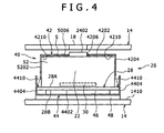
- Fig. 4 is a sectional view of the camera module 20 in the state of being incorporated in the first casing 14
- Figs. 5A and 5B and Figs. 6A and 6B are perspective views of the camera module 20 from which a shield case 40 has been removed.
- the camera module 20 includes a camera body 22 and the shield case 40.
- the camera body 22 includes a lens-barrel 26 holding a shooting optical system 24, a substrate 28 attached to the lens-barrel 26, an image pickup device 30 incorporated in the lens-barrel 26 and operative to pick up an image focused by the shooting optical system 24 and to output an image pickup signal, and a signal processing unit 32 provided on the substrate 28 and operative to receive the image pickup signal outputted from the image pickup device 30 and to perform a predetermined signal processing (see Figs. 7 and 8 .
- the lens-barrel 26 has a front end and a rear end at both side positions along the optical axis of the shooting optical system 24, and an optical member 2402 (in this embodiment, a lens cover) constituting the shooting optical system 24 and located at a frontmost position is disposed in the state of being exposed at the front end of the lens-barrel 26.
- an optical member 2402 in this embodiment, a lens cover
- the lens-barrel 26 is rectangular in shape, and is provided in its center with a containing space penetrating therethrough in the front-rear direction, in other words, extending along the optical axis of the shooting optical system 24.
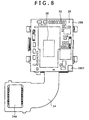
- Fig. 7 is a perspective view of the camera module 20, with a rear split body 44 detached therefrom, and Fig. 8 is a view along arrow A of Fig. 7 .
- the substrate 28 is attached to the rear end of the lens-barrel 26.
- the substrate 28 is rectangular in shape, and includes a front surface 28A fronting on the lens-barrel 26, and a rear surface 28B located on the opposite side.
- the substrate 28 is formed with a profile greater than that of the rear surface constituting the rear end of the lens-barrel 26, and the four side portions of the substrate 28 protrude to the outside of the four sides of the rear surface of the lens-barrel 26.
- a flexible substrate 34 is laid on the front surface 28A and attached to the front surface 28A by soldering, and an image pickup device 30 is mounted in a location where the flexible substrate 34 fronts on the lens-barrel 26.
- Electronic component parts inclusive of various ICs and the like constituting the signal processing unit 32 are mounted on the rear surface 28B.
- the rear surface 28B is provided with a ground land 2802 set at a reference potential.
- symbol 34A denotes a connector provided at the tip end of the flexible substrate 34.
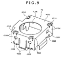
- Fig. 9 , 10A and 10B are perspective views of a front split body 42 constituting the shield case 40
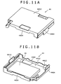
- Fig. 11A is a perspective view of the rear split body 44 constituting the shield case 40
- Fig. 11B is a perspective view, from inside, of the rear split body 44 constituting the shield case 40.
- the shield case 40 is configured to cover the lens-barrel 26 and the substrate 28 and to provide electromagnetic shielding for the image pickup device 30 and the signal processing unit 32.
- the shield case 40 in this embodiment, is composed of the front split body 42 covering a front portion of the lens-barrel 26, and the rear split body 44 covering a rear portion of the lens-barrel 26.
- the front split body 42 and the rear split body 44 are both formed of an electrically conductive and non-magnetic material such as phosphor bronze, nickel silver, tinplate and copper.
- the rear split body 44 has a rectangular substrate covering plate part 4402, and side surface portions 4404 rising up from the four sides of the substrate covering plate part 4402 and extending along the side portions of the lens-barrel 26.
- one opposed pair of side surface portions 4404 are provided with lock parts 4410 which are disengageably locked to the front surface 28A of the substrate 28 and the locking of which inhibits the substrate covering plate part 4402 from moving in a direction of spacing away from the substrate 28.
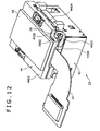
- Fig. 12 is a perspective view, from the rear side, of the camera module 20, and Fig. 13 is an enlarged perspective view of a main part of Fig. 12 .
- a grounding contact piece 4420 for grounding the shield case 40 is provided at the side surface portion 4404.
- the grounding contact piece 4420 is projected from the side surface portion 4404, extends in a direction intersecting with the direction of spacing away and approaching of the substrate covering plate part 4402 relative to the substrate 28, and has a tip portion joined to the ground land 2802 by soldering.
- the side surface portion 4404 is provided with an arm portion 4422 which projects from the side surface portion 4404, extends in a direction intersecting with the direction of spacing away and approaching of the substrate covering plate part 4402 relative to the substrate 28, and is elastically deformable in the direction of spacing away and approaching of the substrate covering plate part 4402 relative to the substrate 28.
- the grounding contact piece 4420 is provided at the tip end of the arm portion 4422.
- an insulating and elastic cushion material 46 is disposed between the substrate 28 and the substrate covering plate part 4402.
- the cushion material 46 there can be used an insulating and non-magnetic material, for example, foamed polyurethane or the like.
- foamed polyurethane is higher than air in thermal conductivity.
- the cushion material 46 is disposed in a compressed state between the substrate 28 and the substrate covering plate part 4402.
- lock parts 4410 are normally locked to the camera body 22 by the elastic force of the cushion material 46, whereby the rear split body 44 is mounted on the camera body 22 without possibility of chattering.
- the cushion material 46 is composed of a plate-like member having a uniform thickness, so that the substrate 28 and the substrate covering plate part 4402 are parallel to each other.
- Fig. 14 is an enlarged view of main parts of the front split body 42 and the rear split body 44.
- a part 4204A of the tip end of the side surface portion 4204 of the front split body 42 and a part 4404A of the tip end of the side surface portion 4404 of the rear split body 44 make elastic contact with each other, whereby the front split body 42 and the rear split body 44 are electrically connected to each other.
- a plate-like rubber vibration isolator 48 is interposed on the outside surface of the substrate covering plate part 4402, and four leg parts 5250 (see Fig. 18 ) projected from the lens-barrel body 52 are attached to an inside wall 1410 of the first casing 14, whereby the camera module 20 is disposed in position.
- the four leg parts 5250 projected from the lens-barrel body 52 are engaged with engaging parts of the inside wall 1410 of the first casing 14, whereby the rubber vibration isolator 48 is mounted in a compressed state and is made to display a cushioning action so as to prevent the rear split body 44 from slipping out of position.
- the cushion material 46 is disposed in a compressed state between the substrate 28 and the substrate covering plate part 4402 and the lock part 4410 is normally locked to the camera body 22 by the elastic force of the cushion material 46, this configuration is advantageous in mounting the rear split body 44 on the camera body 22 without possibility of chattering.
- the cushion material 46 is composed of a material higher than air in thermal conductivity, such as foamed polyurethane, the heat generated in the substrate 28 will easily be transferred to the rear split body 44 through the cushion material 46, which is advantageous for efficient cooling of the substrate 28.
- grounding contact piece 4420 put in contact with the ground land 2802 may be configured as follows.
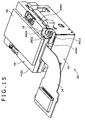
- Fig. 15 is a perspective view, from the rear side, of a camera module
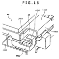
- Fig. 16 is an enlarged perspective view of a main part of Fig. 15 .
- grounding contact piece 4420 and the ground land 2802 are joined to each other by soldering in the above-described embodiment, in this embodiment a grounding contact piece 4420 and the ground land 2802 are normally kept in contact with each other by utilizing the elasticity of the arm part 4422; other points of configuration in this embodiment are the same as in the above-described embodiment.
- the arm part 4422 is provided which projects from the side surface portion 4404, extends in a direction intersecting the direction of spacing away and approaching of the substrate covering plate part 4402 relative to the substrate 28, and is deformable in the direction of spacing away and approaching of the substrate covering plate part 4402 relative to the substrate 28.
- the arm part 4422 is provided at its tip end with the grounding contact piece 4420 capable of making contact with the ground land 2802.
- the grounding contact piece 4420 is put into contact with the ground land 2802 and the contact condition is maintained, by the elasticity of the arm part 4422.
- grounding contact piece 4420 According to such a grounding contact piece 4420, the need for a soldering work is eliminated, which is advantageous in contriving a simpler assemblage, as compared with the case where the grounding contact piece 4420 and the ground land 2802 are soldered to each other.
- the force exerted on the joint portion between the grounding contact piece 4420 and the ground land 2802 can be lessened, which is more advantageous in securing the shock resistance of the joint portion between the grounding contact piece 4420 and the ground land 2802.
- lock part 4410 may be locked to the front split body 42.
- Fig. 17 is a sectional view of a camera module 20 in the state of being incorporated in a first casing 14.
- lock parts 4410 for inhibiting the substrate covering plate part 4402 from moving away from the substrate 28 are locked to the camera body 22 in the above-described embodiment, in this embodiment lock parts 4410A are locked to a front split body 42; the other points of configuration in this embodiment are the same as in the above-described embodiment.
- lock parts 4410A are provided at tip ends of one pair of side surface portions 4404 of two opposed pairs of side surface portions 4404 of the rear split body 44.
- the lock parts 4410A can be locked to lock parts 4230 of the front split body 42, and, by the locking of the lock parts 4410A to the lock parts 4230 of the front split body 42, the substrate covering plate part 4402 is inhibited from moving away from the substrate 28.
- a plate-like rubber vibration isolator 48 is interposed on the outside surface of the substrate covering plate part 4402, and four leg portions 5250 (see Fig. 18 ) projected from the lens-barrel body 52 are attached to the inside wall 1410 of the first casing 14, whereby the camera module 20 is disposed in position.
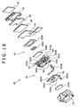
- Fig. 18 is an exploded perspective view, from the front side, of the camera module 20
- Fig. 19 is an exploded perspective view, from the rear side, of the camera module 20.
- the lens-barrel 26 is configured by stacking a plurality of lens-barrel component members.
- the lens-barrel 26 is configured by stacking a shutter supporting housing 50 and a lens-barrel body 52 along the optical axis direction of the shooting optical system 24.
- the lens-barrel body 52 is configured by stacking a front lens-barrel 54 and a rear lens-barrel 56 along the optical axis direction of the shooting optical system 24, and the front lens-barrel 54 and the rear lens-barrel 56 are joined to each other by a UV-curable type adhesive (UV adhesive).
- UV adhesive UV-curable type adhesive
- the shutter supporting housing 50 as well as the front lens-barrel 54 and the rear lens-barrel 56 have dispersions of dimensions thereof, but the dispersions are within the respective ranges of permissible errors.
- the shutter supporting housing 50 is provided in its center with an aperture 5002 of an optical path of the shooting optical system 24, and a shutter (not shown) for opening and closing the aperture 5002 and a shutter driving unit (not shown) are provided in the inside of the shutter supporting housing 50.
- the shutter supporting housing 50 corresponds to the front end lens-barrel component member located at the front end in the optical axis direction of the shooting optical system, of the plurality of lens-barrel component members stacked together, in the present invention.
- the shutter supporting housing 50 is connected to a boss part 5401 of the front lens-barrel 54 by a screw 5004, in the state of being positioned relative to the front lens-barrel 54.
- a portion on the opposite side of the front lens-barrel 54 is formed as a flat front surface 5006, and a portion on the opposite side of the front surface 5006 is formed as a flat rear surface 5008.
- An optical member 2402 (lens cover) constituting the shooting optical system 24 and located at the frontmost end in the optical axis direction of the shooting optical system 24 is attached to the front surface 5006 by a double sided pressure sensitive adhesive tape so as to close the aperture 5002.
- symbol 5010 denotes a flexible substrate configured to control the above-mentioned shutter driving unit.
- the front lens-barrel 54 has a front surface 5402 mated to the rear surface 5008 of the shutter supporting housing 50, and the front surface 5402 is rectangular in shape.
- a front portion of the lens-barrel body 52 has a front surface 5006, and side portions of the lens-barrel body 52 have four side surfaces 5202 corresponding to the four sides of the front surface 5006.
- one side surface 5202 is projectingly provided with two lock projections 5210, the remaining two side surfaces 5202 are each provided with a single lock projection 5210, and the remaining one side surface is not provided with such a projection.
- the lock projections 5210 are provided in the front lens-barrel 54.
- symbol 3002 denotes a CMOS sensor as an image pickup sensor mounted on the flexible substrate 34 and operative to pick up an image of an object and to produce an image pickup signal
- symbol 3004 denotes a rectangular package attached to the flexible substrate 34 so as to contain the CMOS sensor 3002
- symbol 3006 denotes a cover glass covering the front surface of the package 3004 and sealing the CMOS sensor 3002 in the package 3004.
- the CMOS sensor 3002, the package 3004, and the cover glass 3006 constitute the image pickup device 30.
- the CMOS sensor 3002 is used as the image pickup sensor in this embodiment, the present invention is not limited to this configuration, and, naturally, a CCD sensor or other known sensors can also be used.
- the front split body 42 has a rectangular front surface covering plate part 4202 covering the front surface 5006 of the shutter supporting housing 50, and four side surface portions 4204 bent from the four sides of the front surface covering plate part 4202.
- the front surface covering plate part 4202 is provided with an opening 4206 at a position corresponding to the optical member 2402 (lens cover).
- spring pieces 4210 are integrally formed at four positions along the periphery of the front surface covering plate part 4202.
- the spring pieces 4210 are each provided over the range from the front surface covering plate part 4202 to the side surface portion 4204 so as to be elastically deformable in the direction of spacing away from and approaching the front surface covering plate part 4202, in other words, to be elastically deformable in the optical axis direction of the shooting optical system 24, and further in other words, to be elastically deformable in the direction of stacking of the plurality of lens-barrel component members.
- two spring pieces 4210 are formed at both ends of one side of the front surface covering plate part 4202, and one spring piece 4210 is formed at an end portion of each of the two sides intersecting with the one side.
- the side surface portion 4204 provided with two spring piece 4210 is formed with a locking opening 4208 at a position spaced from the spring piece 4210 along the elastic deformation direction of the spring piece 4210 (along the stacking direction of the plurality of lens-barrel component members).
- the side surface portion 4204 provided with one spring piece 4210 is formed with a locking opening 4208 at a position spaced from the spring piece 4210 along the elastic deformation direction of the spring piece 4210 (along the stacking direction of the plurality of lens-barrel component members).
- a vertically extending vertical groove 4212 is provided in a side portion relative to one locking opening 4208.
- a bent piece 4220 bent to the outside of the side surface portion 4204 is provided so that, at the time of mounting the front split body 42 onto the camera body 22 (the lens-barrel body 52), the lock projections 5210 will be smoothly guided to the corresponding locking openings 4208.
- the profile of the four sides of the shutter supporting housing 50 is slightly larger than the profile of the four side surfaces 5202 of the lens-barrel body 52; therefore, with the inside surfaces of the four side surface portions 4204 abutted on the four sides of the shutter supporting housing 50, the front split body 42 is positioned in the direction orthogonal to the optical axis direction of the shooting optical system 24, and the center of the opening 4206 of the front split body 42 is aligned to the optical axis of the shooting optical system 24 (the center of the optical member 2402 (lens cover)).
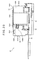
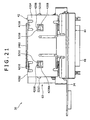
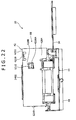
- Figs. 20 to 23 are side views showing the condition where the front split body 42 and the rear split body 44 are mounted to the lens-barrel 26, in which Fig. 20 corresponds to a view along arrow A of Fig. 2B , Fig. 21 corresponds to a view along arrow B of Fig. 2B , Fig. 22 corresponds to a view along arrow C of Fig. 2B , and Fig. 23 corresponds to a view along arrow D of Fig. 2B .
- the front surface covering plate part 4202 and the side surface portions 4204 cover the front surface 5006 and the side surfaces 5202 of the lens-barrel body 52, the spring pieces 4210 are locked to the front surface 5006 (the front surface 2602), and the lock projections 5210 are inserted into the locking openings 4208, whereon the spring pieces 4210 are elastically deformed, the spring pieces 4210 are pressed against the front surface 5006, and the portion of each lock projection 5210 located oppositely to the front surface 5006 is normally pressed against the edge 4208A, located at a position away from the spring piece 4210, of the locking opening 4208.
- the front surface 5006 of the lens-barrel body 52 constitutes a lock surface to which the spring pieces 4210 are locked.
- the spring pieces 4210, the front surface 5006 of the lens-barrel body 52, the lock projections 5210, and the locking openings 4208 constitute a clamping mechanism 60 which functions so that the portion of the two adjacent lens-barrel component members is clamped from both ends in the above-mentioned stacking direction, whereby the shield case 40 is positioned relative to the lens-barrel 26 and mounted to the lens-barrel 26, in the stacking direction.
- a gap S along the optical axis direction of the shooting optical system 24 is secured between the front surface covering plate part 4202 of the shield case 40 and the front surface 2602 of the lens-barrel 26.
- the clamping mechanism 60 is provided so that the portion of the stacked and adjacent two lens-barrel component members, i.e., the portion of the shutter supporting housing 50 and the lens-barrel body 52, is clamped by the shield case 40 (the front split body 42) from both sides in the direction of the stacking. Therefore, even if the dispersions of dimensions of the shutter supporting housing 50 and the lens-barrel body 52 are added in the stacking direction, this configuration is advantageous in positioning the front split body 42 relative to the lens-barrel body 52 in the stacking direction, and in mounting the front split body 42 onto the lens-barrel body 52 without possibility of chattering in the stacking direction.
- the spring pieces 4210 provided in the front split body 42 are pressed against the front surface 5006 (lock surface) of the lens-barrel body 52, and the portions where the lock projections 5210 inserted in the locking openings 4208 are located oppositely to the front surface 5006 are pressed against the edges 4208A, located at positions spaced away from the spring pieces 4210, of the locking openings 4208.
- this configuration is advantageous for accurately positioning the shield case 40 (the front split body 42) relative to the lens-barrel body 52 in the stacking direction, with the portions where the lock projections 5210 are located oppositely to the front surface 5006 as a reference, or with the edges 4208A, located at positions spaced from the spring pieces 4210, of the locking openings 4208, as a reference.
- the condition where the shield case 40 (the front split body 42) is accurately positioned relative to the lens-barrel body 52 without possibility of chattering in the above-mentioned stacking direction is advantageous in preventing the so-called eclipse, i.e., the phenomenon in which the optical path ranging from an object to be shot to the shooting optical system 24 of the lens-barrel body 52 is obstructed by an edge portion constituting the opening 4206 of the shield case 40.
- the gap S is secured between the front surface covering plate part 4202 of the shield case 40 and the front surface 5006 of the lens-barrel body 52. Therefore, where an external force in a rearward direction of from the front side of the camera module 20 toward the lens-barrel body 52, the presence of the gap S as above-mentioned is advantageous for lessening the impact on the front surface 5006 of the lens-barrel 52.
- the present invention naturally is applicable to the case where a plurality of lens-barrel component members are stacked in a direction orthogonal to the optical axis direction of the shooting optical system 24.
- the shield case 40 is positioned relative to the lens-barrel body 52 in the direction of stacking of the plurality of lens-barrel component members, so that the optical path of the shooting optical system 24 and the opening 4206 provided in the shield case 40 can be accurately positioned, which is advantageous in preventing the so-called eclipse.
- the configuration of the clamping mechanism 60 is not limited to this configuration, and known various clamping structures may be adopted.
- the configuration of the clamping mechanism 60 as in the above embodiment is advantageous for simplifying the structure.
- the number of the lens-barrel component members may naturally be three or more.
- the present invention is widely applicable to portable information terminals such as PDA, notebook type personal computers, etc. and various shooting apparatuses such as digital still cameras, video cameras, etc.
Landscapes
- Engineering & Computer Science (AREA)
- Multimedia (AREA)
- Signal Processing (AREA)
- Physics & Mathematics (AREA)
- General Physics & Mathematics (AREA)
- Studio Devices (AREA)
- Lens Barrels (AREA)
- Camera Bodies And Camera Details Or Accessories (AREA)
- Transforming Light Signals Into Electric Signals (AREA)
Description
- The present invention relates to a camera module and an electronic apparatus.
- In recent years there have been provided electronic apparatuses such as cellular phones and PDAs (Personal Digital Assistants) in which a camera module is incorporated.
- A camera module includes a lens-barrel holding a shooting optical system, a substrate attached to the rear end of the lens-barrel, an image pickup device incorporated in the lens-barrel and operative to pick up an image of an object guided by the shooting optical system and to output an image pickup signal, and a signal processing unit provided on the substrate and operative to receive the image pickup signal outputted from the image pickup device and to perform a predetermined signal processing, and a shield case is provided for covering the lens-barrel and the substrate and providing electromagnetic shielding for the image pickup device and the signal processing unit (refer to, for example,
Japanese Patent Laid-open No. 2005-86341 - Other examples of a camera module are given by the prior art documents
US2004075620 andDE10317827 . - Meanwhile, the lens-barrel of such a camera module is in many cases configured by stacking a plurality of lens-barrel component members.
- In such a lens-barrel, even where the dispersions of dimensions of each lens-barrel component member are within the respective ranges of permissible errors, the dispersions of dimensions of the lens-barrel component members are added in the direction of stacking of the plurality of lens-barrel component members.
- Therefore, how to position the shield case relative to the lens-barrel configured by stacking the plurality of lens-barrel component members and how to mount the shield case to the lens-barrel without possibility of chattering in the stacking direction of the plurality of lens-barrel component members are important problems.
- Thus, there is a need for a camera module and an electronic apparatus which are advantageous for positioning a shield case relative to a lens-barrel and mounting the shield case to the lens-barrel without possibility of chattering, in the direction of stacking of a plurality of lens-barrel component members.
- According to an embodiment of the present invention, there is provided a camera module including a camera body and a shield case. The camera body including: a lens-barrel holding a shooting optical system; a substrate attached to the lens-barrel; an image pickup device incorporated in the lens-barrel and operative to pick up an image of an object focused by the shooting optical system and to output an image pickup signal; and a signal processing unit provided on the substrate and operative to receive the image pickup signal outputted from the image pickup device and to perform a predetermined signal processing. The shield case covering the lens-barrel and the substrate and operative to provide electromagnetic shielding for the image pickup device and the signal processing unit. The lens-barrel includes a plurality of lens-barrel component members stacked together, and a clamping mechanism is provided by which a portion of two lens-barrel component members adjacent to each other is clamped from both ends in the direction of said stacking, whereby the shield case is positioned relative to the lens-barrel and mounted to the lens-barrel, in the direction of the stacking. The clamping mechanism includes: an elastically deformable spring piece provided in said shield case; a locking opening provided at a position of said shield case spaced from said spring piece along the direction of elastic deformation of said spring piece; a lock surface which is provided in one of two said lens-barrel component members adjacent to each other and to which said spring piece is locked; and a projection which is provided in the other of two said lens-barrel component members adjacent to each other and which is inserted in said locking opening; wherein, by the locking of said spring piece to said lock surface and the insertion of said projection in said locking opening, said spring piece is elastically deformed, said spring piece is pressed against said lock surface, and a portion of said projection located oppositely to said lock surface is normally pressed against to an edge, located at a position spaced from said spring piece, of said locking opening.
- Besides, according to another embodiment of the present invention, there is provided an electronic apparatus including a casing, and a camera module according to the above characteristics incorporated in the casing.
- According to the present invention, the clamping mechanism for clamping a portion of two adjacent lens-barrel component members by the shield case from both ends in the direction of stacking of the lens-barrel component members is provided. Therefore, even if the dispersions of dimensions of the lens-barrel component members are added in the stacking direction, this configuration is advantageous for positioning the shield case relative to the lens-barrel in the stacking direction and for mounting the shield case to the lens-barrel without possibility of chattering in the stacking direction of the two lens-barrel component members.
- The above and other features and advantages of the present invention will become apparent from the following description when taken in conjunction with the accompanying drawings which illustrate preferred embodiments of the present invention by way of example.
-
-
Figs. 1A and 1B each show an appearance of an example of a cellular phone with a camera module incorporated therein; -
Figs. 2A and 2B are perspective views of the camera module; -
Figs. 3A and 3B are perspective views of the camera module; -
Fig. 4 is a sectional view of the camera module in the state of being incorporated in a first casing; -
Figs. 5A and 5B are perspective views of the camera module from which a shield case has been detached; -
Figs. 6A and 6B are perspective views of the camera module from which the shield case has been detached; -
Fig. 7 is a perspective view of the camera module, with a rear split body detached therefrom -
Fig. 8 is a view along arrow A ofFig. 7 ; -
Fig. 9 is a perspective view of a front splitbody 42 constituting the shield case; -
Figs. 10A and 10B are perspective views of the front split body constituting the shield case; -
Fig. 11A is a perspective view of the rear split body constituting the shield case, andFig. 11B is a perspective view, from inside, of the rear split body constituting the shield case; -
Fig. 12 is a perspective view, from the rear side, of the camera module; -
Fig. 13 is an enlarged perspective view of a main part ofFig. 12 ; -
Fig. 14 is an enlarged view of main parts of the front split body and the rear split body; -
Fig. 15 is a perspective view, from the rear side, of the camera module; -
Fig. 16 is an enlarged perspective view of a main part ofFig. 15 ; -
Fig. 17 is a sectional view of the camera module; -
Fig. 18 is an exploded perspective view, from the front side, of the camera module; -
Fig. 19 is an exploded perspective view, from the rear side, of the camera module; -
Fig. 20 is a side view showing the condition where the front split body and the rear split body mounted to a lens-barrel (corresponding to a view along arrow A ofFig. 2B ); -
Fig. 21 is a side view showing the condition where the front split body and the rear split body are mounted to the lens-barrel (corresponding to a view along arrow B ofFig. 2B ); -
Fig. 22 is a side view showing the condition where the front split body and the rear split body are mounted to the lens-barrel (corresponding to a view along arrow C ofFig. 2B ); and -
Fig. 23 is a side view showing the condition where the front split body and the rear split body are mounted to the lens-barrel (corresponding to a view along arrow D ofFig. 2B ). - Now, a first embodiment of the present invention will be described below referring to the drawings.
-
Figs. 1A and 1B each show an appearance of an example of acellular phone 10 as an electronic apparatus with a camera module incorporated therein. - As shown in
Figs. 1A and 1B , thecellular phone 10 has first andsecond casings hinge portion 12. - A liquid
crystal display panel 1402 is provided at the inside surface of thefirst casing 14, andoperating switches 1602 such as ten-keys and functional keys are provided at the inside surface of thesecond casing 16. - A
camera module 20 is incorporated in a base end portion of thefirst casing 14, and an image shot by thecamera module 20 is displayed on the liquidcrystal display panel 1402. -
Figs. 2A and 2B andFigs. 3A and 3B are perspective views of thecamera module 20,Fig. 4 is a sectional view of thecamera module 20 in the state of being incorporated in thefirst casing 14, andFigs. 5A and 5B andFigs. 6A and 6B are perspective views of thecamera module 20 from which ashield case 40 has been removed. - The
camera module 20 includes acamera body 22 and theshield case 40. - As shown in
Figs. 4 ,5A and 5B , thecamera body 22 includes a lens-barrel 26 holding a shootingoptical system 24, asubstrate 28 attached to the lens-barrel 26, animage pickup device 30 incorporated in the lens-barrel 26 and operative to pick up an image focused by the shootingoptical system 24 and to output an image pickup signal, and asignal processing unit 32 provided on thesubstrate 28 and operative to receive the image pickup signal outputted from theimage pickup device 30 and to perform a predetermined signal processing (seeFigs. 7 and8 . - The lens-
barrel 26 has a front end and a rear end at both side positions along the optical axis of the shootingoptical system 24, and an optical member 2402 (in this embodiment, a lens cover) constituting the shootingoptical system 24 and located at a frontmost position is disposed in the state of being exposed at the front end of the lens-barrel 26. - The lens-
barrel 26 is rectangular in shape, and is provided in its center with a containing space penetrating therethrough in the front-rear direction, in other words, extending along the optical axis of the shootingoptical system 24. -
Fig. 7 is a perspective view of thecamera module 20, with arear split body 44 detached therefrom, andFig. 8 is a view along arrow A ofFig. 7 . - As shown in
Figs. 5 to 8 , thesubstrate 28 is attached to the rear end of the lens-barrel 26. - The
substrate 28 is rectangular in shape, and includes afront surface 28A fronting on the lens-barrel 26, and arear surface 28B located on the opposite side. - The
substrate 28 is formed with a profile greater than that of the rear surface constituting the rear end of the lens-barrel 26, and the four side portions of thesubstrate 28 protrude to the outside of the four sides of the rear surface of the lens-barrel 26. - A
flexible substrate 34 is laid on thefront surface 28A and attached to thefront surface 28A by soldering, and animage pickup device 30 is mounted in a location where theflexible substrate 34 fronts on the lens-barrel 26. - Electronic component parts inclusive of various ICs and the like constituting the
signal processing unit 32 are mounted on therear surface 28B. - Besides, the
rear surface 28B is provided with aground land 2802 set at a reference potential. - Incidentally, in
Figs. 7 and8 ,symbol 34A denotes a connector provided at the tip end of theflexible substrate 34. -
Fig. 9 ,10A and 10B are perspective views of afront split body 42 constituting theshield case 40,Fig. 11A is a perspective view of therear split body 44 constituting theshield case 40, andFig. 11B is a perspective view, from inside, of therear split body 44 constituting theshield case 40. - The
shield case 40 is configured to cover the lens-barrel 26 and thesubstrate 28 and to provide electromagnetic shielding for theimage pickup device 30 and thesignal processing unit 32. - The
shield case 40, in this embodiment, is composed of thefront split body 42 covering a front portion of the lens-barrel 26, and therear split body 44 covering a rear portion of the lens-barrel 26. - The front split
body 42 and therear split body 44 are both formed of an electrically conductive and non-magnetic material such as phosphor bronze, nickel silver, tinplate and copper. - First, the
rear split body 44 of theshield case 40 will be described as follows. - As shown in
Figs. 11A and 11B , therear split body 44 has a rectangular substrate coveringplate part 4402, andside surface portions 4404 rising up from the four sides of the substrate coveringplate part 4402 and extending along the side portions of the lens-barrel 26. - Of the two opposed pairs of
side surface portions 4404, one opposed pair ofside surface portions 4404 are provided withlock parts 4410 which are disengageably locked to thefront surface 28A of thesubstrate 28 and the locking of which inhibits the substrate coveringplate part 4402 from moving in a direction of spacing away from thesubstrate 28. -
Fig. 12 is a perspective view, from the rear side, of thecamera module 20, andFig. 13 is an enlarged perspective view of a main part ofFig. 12 . - A
grounding contact piece 4420 for grounding theshield case 40 is provided at theside surface portion 4404. - The
grounding contact piece 4420 is projected from theside surface portion 4404, extends in a direction intersecting with the direction of spacing away and approaching of the substrate coveringplate part 4402 relative to thesubstrate 28, and has a tip portion joined to theground land 2802 by soldering. - Specifically, the
side surface portion 4404 is provided with anarm portion 4422 which projects from theside surface portion 4404, extends in a direction intersecting with the direction of spacing away and approaching of the substrate coveringplate part 4402 relative to thesubstrate 28, and is elastically deformable in the direction of spacing away and approaching of the substrate coveringplate part 4402 relative to thesubstrate 28. Thegrounding contact piece 4420 is provided at the tip end of thearm portion 4422. - As shown in
Fig. 4 and11B , an insulating andelastic cushion material 46 is disposed between thesubstrate 28 and the substrate coveringplate part 4402. - As the
cushion material 46, there can be used an insulating and non-magnetic material, for example, foamed polyurethane or the like. Incidentally, foamed polyurethane is higher than air in thermal conductivity. - Besides, as shown in
Fig. 4 , with thelock parts 4410 locked to the camera body 22 (in this embodiment, thefront surface 28A of the substrate 28), thecushion material 46 is disposed in a compressed state between thesubstrate 28 and the substrate coveringplate part 4402. - In other words, the
lock parts 4410 are normally locked to thecamera body 22 by the elastic force of thecushion material 46, whereby therear split body 44 is mounted on thecamera body 22 without possibility of chattering. - The
cushion material 46 is composed of a plate-like member having a uniform thickness, so that thesubstrate 28 and the substrate coveringplate part 4402 are parallel to each other. -
Fig. 14 is an enlarged view of main parts of thefront split body 42 and therear split body 44. - As shown in
Fig. 14 , in the condition where thefront split body 42 and therear split body 44 are mounted on thecamera body 22, apart 4204A of the tip end of theside surface portion 4204 of thefront split body 42 and apart 4404A of the tip end of theside surface portion 4404 of therear split body 44 make elastic contact with each other, whereby thefront split body 42 and therear split body 44 are electrically connected to each other. - Besides, in this embodiment, as shown in
Fig. 4 , in incorporating thecamera module 20 into a base end portion of thefirst casing 14, a plate-likerubber vibration isolator 48 is interposed on the outside surface of the substrate coveringplate part 4402, and four leg parts 5250 (seeFig. 18 ) projected from the lens-barrel body 52 are attached to aninside wall 1410 of thefirst casing 14, whereby thecamera module 20 is disposed in position. To be more specific, the fourleg parts 5250 projected from the lens-barrel body 52 are engaged with engaging parts of theinside wall 1410 of thefirst casing 14, whereby therubber vibration isolator 48 is mounted in a compressed state and is made to display a cushioning action so as to prevent therear split body 44 from slipping out of position. - With such a
rear split body 44 provided, the following effects are displayed. - Even if an impact is exerted on the
camera module 20 due to dropping of thecellular phone 10 or the like, the presence of thecushion material 46 interposed between the substrate coveringplate part 4402 and thesubstrate 28, in addition to the cushioning action of therubber vibration isolator 48, ensures that the cushioning action of thecushion material 46 prevents an irrational force from acting on the portion between therear split body 44 and thesubstrate 28, which is advantageous in securing the impact resistance of thecamera module 20. - In addition, since the
cushion material 46 is disposed in a compressed state between thesubstrate 28 and the substrate coveringplate part 4402 and thelock part 4410 is normally locked to thecamera body 22 by the elastic force of thecushion material 46, this configuration is advantageous in mounting therear split body 44 on thecamera body 22 without possibility of chattering. - Besides, since the
rear split body 44 is joined to theground land 2802 of thesubstrate 28 through thearm part 4422 and thegrounding contact piece 4420, an impact force will be damped by flexure of thearm part 4422 when an impact is exerted on thecamera module 20. Therefore, an irrational force would not act on the joint portion between thegrounding contact piece 4420 and theground land 2802, which is advantageous in securing the shock resistance of the joint portion between thegrounding contact piece 4420 and theground land 2802. - Further, where the
cushion material 46 is composed of a material higher than air in thermal conductivity, such as foamed polyurethane, the heat generated in thesubstrate 28 will easily be transferred to therear split body 44 through thecushion material 46, which is advantageous for efficient cooling of thesubstrate 28. - Incidentally, the
grounding contact piece 4420 put in contact with theground land 2802 may be configured as follows. -
Fig. 15 is a perspective view, from the rear side, of a camera module, andFig. 16 is an enlarged perspective view of a main part ofFig. 15 . - While the
grounding contact piece 4420 and theground land 2802 are joined to each other by soldering in the above-described embodiment, in this embodiment agrounding contact piece 4420 and theground land 2802 are normally kept in contact with each other by utilizing the elasticity of thearm part 4422; other points of configuration in this embodiment are the same as in the above-described embodiment. - In this embodiment, the
arm part 4422 is provided which projects from theside surface portion 4404, extends in a direction intersecting the direction of spacing away and approaching of the substrate coveringplate part 4402 relative to thesubstrate 28, and is deformable in the direction of spacing away and approaching of the substrate coveringplate part 4402 relative to thesubstrate 28. - The
arm part 4422 is provided at its tip end with thegrounding contact piece 4420 capable of making contact with theground land 2802. - The
grounding contact piece 4420 is put into contact with theground land 2802 and the contact condition is maintained, by the elasticity of thearm part 4422. - According to such a
grounding contact piece 4420, the need for a soldering work is eliminated, which is advantageous in contriving a simpler assemblage, as compared with the case where thegrounding contact piece 4420 and theground land 2802 are soldered to each other. - In addition, since the
grounding contact piece 4420 and theground land 2802 are not fixed rigidly, the force exerted on the joint portion between thegrounding contact piece 4420 and theground land 2802 can be lessened, which is more advantageous in securing the shock resistance of the joint portion between thegrounding contact piece 4420 and theground land 2802. - Besides, the
lock part 4410 may be locked to thefront split body 42. -
Fig. 17 is a sectional view of acamera module 20 in the state of being incorporated in afirst casing 14. - While the
lock parts 4410 for inhibiting the substrate coveringplate part 4402 from moving away from thesubstrate 28 are locked to thecamera body 22 in the above-described embodiment, in thisembodiment lock parts 4410A are locked to afront split body 42; the other points of configuration in this embodiment are the same as in the above-described embodiment. - Specifically, the
lock parts 4410A are provided at tip ends of one pair ofside surface portions 4404 of two opposed pairs ofside surface portions 4404 of therear split body 44. - The
lock parts 4410A can be locked to lockparts 4230 of thefront split body 42, and, by the locking of thelock parts 4410A to thelock parts 4230 of thefront split body 42, the substrate coveringplate part 4402 is inhibited from moving away from thesubstrate 28. - In addition, a plate-like
rubber vibration isolator 48 is interposed on the outside surface of the substrate coveringplate part 4402, and four leg portions 5250 (seeFig. 18 ) projected from the lens-barrel body 52 are attached to theinside wall 1410 of thefirst casing 14, whereby thecamera module 20 is disposed in position. - By
such lock parts 4410, also, the same effects as in the above-described embodiment are displayed. - Incidentally, while the case where an elastic and insulating plate-like member is used as the
cushion material 46 has been described, a single or a plurality of coil springs formed from an elastic and insulating wire or the like can be used as thecushion material 46. However, the use of the plate-like member as in the above-described embodiment is advantageous in contriving a simpler structure and an easier assemblage. - Now, the portion of the lens-
barrel 26 covered with thefront split body 42, thefront split body 42, and aclamping mechanism 60, which are main parts in the present invention, will be described below. -
Fig. 18 is an exploded perspective view, from the front side, of thecamera module 20, andFig. 19 is an exploded perspective view, from the rear side, of thecamera module 20. - The lens-
barrel 26 is configured by stacking a plurality of lens-barrel component members. - Specifically, the lens-
barrel 26 is configured by stacking ashutter supporting housing 50 and a lens-barrel body 52 along the optical axis direction of the shootingoptical system 24. To be more specific, the lens-barrel body 52 is configured by stacking a front lens-barrel 54 and a rear lens-barrel 56 along the optical axis direction of the shootingoptical system 24, and the front lens-barrel 54 and the rear lens-barrel 56 are joined to each other by a UV-curable type adhesive (UV adhesive). - Incidentally, the
shutter supporting housing 50 as well as the front lens-barrel 54 and the rear lens-barrel 56 have dispersions of dimensions thereof, but the dispersions are within the respective ranges of permissible errors. - The
shutter supporting housing 50 is provided in its center with anaperture 5002 of an optical path of the shootingoptical system 24, and a shutter (not shown) for opening and closing theaperture 5002 and a shutter driving unit (not shown) are provided in the inside of theshutter supporting housing 50. Incidentally, theshutter supporting housing 50 corresponds to the front end lens-barrel component member located at the front end in the optical axis direction of the shooting optical system, of the plurality of lens-barrel component members stacked together, in the present invention. - The
shutter supporting housing 50 is connected to aboss part 5401 of the front lens-barrel 54 by ascrew 5004, in the state of being positioned relative to the front lens-barrel 54. - Of the
shutter supporting housing 50, a portion on the opposite side of the front lens-barrel 54 is formed as a flatfront surface 5006, and a portion on the opposite side of thefront surface 5006 is formed as a flatrear surface 5008. - An optical member 2402 (lens cover) constituting the shooting
optical system 24 and located at the frontmost end in the optical axis direction of the shootingoptical system 24 is attached to thefront surface 5006 by a double sided pressure sensitive adhesive tape so as to close theaperture 5002. - In
Fig. 18 ,symbol 5010 denotes a flexible substrate configured to control the above-mentioned shutter driving unit. - The front lens-
barrel 54 has afront surface 5402 mated to therear surface 5008 of theshutter supporting housing 50, and thefront surface 5402 is rectangular in shape. - Therefore, a front portion of the lens-
barrel body 52 has afront surface 5006, and side portions of the lens-barrel body 52 have fourside surfaces 5202 corresponding to the four sides of thefront surface 5006. - As shown in
Figs. 5 and6 , of the fourside surfaces 5202, oneside surface 5202 is projectingly provided with twolock projections 5210, the remaining twoside surfaces 5202 are each provided with asingle lock projection 5210, and the remaining one side surface is not provided with such a projection. In this embodiment, thelock projections 5210 are provided in the front lens-barrel 54. - Incidentally, in
Figs. 18 and19 ,symbol 3002 denotes a CMOS sensor as an image pickup sensor mounted on theflexible substrate 34 and operative to pick up an image of an object and to produce an image pickup signal,symbol 3004 denotes a rectangular package attached to theflexible substrate 34 so as to contain theCMOS sensor 3002, andsymbol 3006 denotes a cover glass covering the front surface of thepackage 3004 and sealing theCMOS sensor 3002 in thepackage 3004. TheCMOS sensor 3002, thepackage 3004, and thecover glass 3006 constitute theimage pickup device 30. Incidentally, while theCMOS sensor 3002 is used as the image pickup sensor in this embodiment, the present invention is not limited to this configuration, and, naturally, a CCD sensor or other known sensors can also be used. - As shown in
Figs. 4 ,9 ,10A and 10B , thefront split body 42 has a rectangular front surface coveringplate part 4202 covering thefront surface 5006 of theshutter supporting housing 50, and fourside surface portions 4204 bent from the four sides of the front surface coveringplate part 4202. - The front surface covering
plate part 4202 is provided with anopening 4206 at a position corresponding to the optical member 2402 (lens cover). - In addition,
spring pieces 4210 are integrally formed at four positions along the periphery of the front surface coveringplate part 4202. - The
spring pieces 4210 are each provided over the range from the front surface coveringplate part 4202 to theside surface portion 4204 so as to be elastically deformable in the direction of spacing away from and approaching the front surface coveringplate part 4202, in other words, to be elastically deformable in the optical axis direction of the shootingoptical system 24, and further in other words, to be elastically deformable in the direction of stacking of the plurality of lens-barrel component members. - In this embodiment, two
spring pieces 4210 are formed at both ends of one side of the front surface coveringplate part 4202, and onespring piece 4210 is formed at an end portion of each of the two sides intersecting with the one side. - The
side surface portion 4204 provided with twospring piece 4210 is formed with alocking opening 4208 at a position spaced from thespring piece 4210 along the elastic deformation direction of the spring piece 4210 (along the stacking direction of the plurality of lens-barrel component members). - Besides, the
side surface portion 4204 provided with onespring piece 4210 is formed with alocking opening 4208 at a position spaced from thespring piece 4210 along the elastic deformation direction of the spring piece 4210 (along the stacking direction of the plurality of lens-barrel component members). - As shown in
Fig. 10A , a vertically extendingvertical groove 4212 is provided in a side portion relative to onelocking opening 4208. - As shown in
Figs. 9 ,10A and 10B , at an end portion of theside surface portion 4204 passing through eachlocking opening 4208 in the direction of spacing away from the frontsurface plate part 4202, abent piece 4220 bent to the outside of theside surface portion 4204 is provided so that, at the time of mounting thefront split body 42 onto the camera body 22 (the lens-barrel body 52), thelock projections 5210 will be smoothly guided to thecorresponding locking openings 4208. - Incidentally, in plan view, the profile of the four sides of the
shutter supporting housing 50 is slightly larger than the profile of the fourside surfaces 5202 of the lens-barrel body 52; therefore, with the inside surfaces of the fourside surface portions 4204 abutted on the four sides of theshutter supporting housing 50, thefront split body 42 is positioned in the direction orthogonal to the optical axis direction of the shootingoptical system 24, and the center of theopening 4206 of thefront split body 42 is aligned to the optical axis of the shooting optical system 24 (the center of the optical member 2402 (lens cover)). -
Figs. 20 to 23 are side views showing the condition where thefront split body 42 and therear split body 44 are mounted to the lens-barrel 26, in whichFig. 20 corresponds to a view along arrow A ofFig. 2B ,Fig. 21 corresponds to a view along arrow B ofFig. 2B ,Fig. 22 corresponds to a view along arrow C ofFig. 2B , andFig. 23 corresponds to a view along arrow D ofFig. 2B . - As shown in
Figs. 4 and20 to 23 , the front surface coveringplate part 4202 and theside surface portions 4204 cover thefront surface 5006 and the side surfaces 5202 of the lens-barrel body 52, thespring pieces 4210 are locked to the front surface 5006 (the front surface 2602), and thelock projections 5210 are inserted into the lockingopenings 4208, whereon thespring pieces 4210 are elastically deformed, thespring pieces 4210 are pressed against thefront surface 5006, and the portion of eachlock projection 5210 located oppositely to thefront surface 5006 is normally pressed against theedge 4208A, located at a position away from thespring piece 4210, of thelocking opening 4208. In this embodiment, thefront surface 5006 of the lens-barrel body 52 constitutes a lock surface to which thespring pieces 4210 are locked. - In this embodiment, the
spring pieces 4210, thefront surface 5006 of the lens-barrel body 52, thelock projections 5210, and thelocking openings 4208 constitute aclamping mechanism 60 which functions so that the portion of the two adjacent lens-barrel component members is clamped from both ends in the above-mentioned stacking direction, whereby theshield case 40 is positioned relative to the lens-barrel 26 and mounted to the lens-barrel 26, in the stacking direction. - Besides, in this embodiment, as shown in
Fig. 4 , in the condition where the two adjacent lens-barrel component members, i.e., theshutter supporting housing 50 and the lens-barrel body 52, are clamped by the shield case 40 (the front split body 42) through theclamping mechanism 60, a gap S along the optical axis direction of the shootingoptical system 24 is secured between the front surface coveringplate part 4202 of theshield case 40 and thefront surface 2602 of the lens-barrel 26. - According to this embodiment, the
clamping mechanism 60 is provided so that the portion of the stacked and adjacent two lens-barrel component members, i.e., the portion of theshutter supporting housing 50 and the lens-barrel body 52, is clamped by the shield case 40 (the front split body 42) from both sides in the direction of the stacking. Therefore, even if the dispersions of dimensions of theshutter supporting housing 50 and the lens-barrel body 52 are added in the stacking direction, this configuration is advantageous in positioning the front splitbody 42 relative to the lens-barrel body 52 in the stacking direction, and in mounting thefront split body 42 onto the lens-barrel body 52 without possibility of chattering in the stacking direction. - In addition, in this embodiment, the
spring pieces 4210 provided in thefront split body 42 are pressed against the front surface 5006 (lock surface) of the lens-barrel body 52, and the portions where thelock projections 5210 inserted in thelocking openings 4208 are located oppositely to thefront surface 5006 are pressed against theedges 4208A, located at positions spaced away from thespring pieces 4210, of the lockingopenings 4208. Therefore, this configuration is advantageous for accurately positioning the shield case 40 (the front split body 42) relative to the lens-barrel body 52 in the stacking direction, with the portions where thelock projections 5210 are located oppositely to thefront surface 5006 as a reference, or with theedges 4208A, located at positions spaced from thespring pieces 4210, of the lockingopenings 4208, as a reference. - Besides, the condition where the shield case 40 (the front split body 42) is accurately positioned relative to the lens-
barrel body 52 without possibility of chattering in the above-mentioned stacking direction is advantageous in preventing the so-called eclipse, i.e., the phenomenon in which the optical path ranging from an object to be shot to the shootingoptical system 24 of the lens-barrel body 52 is obstructed by an edge portion constituting theopening 4206 of theshield case 40. - In addition, in this embodiment, the gap S is secured between the front surface covering
plate part 4202 of theshield case 40 and thefront surface 5006 of the lens-barrel body 52. Therefore, where an external force in a rearward direction of from the front side of thecamera module 20 toward the lens-barrel body 52, the presence of the gap S as above-mentioned is advantageous for lessening the impact on thefront surface 5006 of the lens-barrel 52. - Incidentally, while the case where a plurality of lens-barrel component members are stacked along the optical axis direction of the shooting
optical system 24 has been described in the above embodiment, the present invention naturally is applicable to the case where a plurality of lens-barrel component members are stacked in a direction orthogonal to the optical axis direction of the shootingoptical system 24. In this case, according to the present invention, theshield case 40 is positioned relative to the lens-barrel body 52 in the direction of stacking of the plurality of lens-barrel component members, so that the optical path of the shootingoptical system 24 and theopening 4206 provided in theshield case 40 can be accurately positioned, which is advantageous in preventing the so-called eclipse. - In addition, while the case where the
spring pieces 4210, thefront surface 5006 of the lens-barrel body 52, thelock projections 5210 and thelocking openings 4208 constitute theclamping mechanism 60 has been described in the above embodiment, the configuration of theclamping mechanism 60 is not limited to this configuration, and known various clamping structures may be adopted. However, the configuration of theclamping mechanism 60 as in the above embodiment is advantageous for simplifying the structure. - Besides, while the case where the plurality of lens-barrel component members include two members, namely, the
shutter supporting housing 50 and the lens-barrel body 52 has been described in the above embodiment, the number of the lens-barrel component members may naturally be three or more. - Furthermore, while the case where the electronic apparatus is a
cellular phone 10 has been described in the above embodiment, the present invention is widely applicable to portable information terminals such as PDA, notebook type personal computers, etc. and various shooting apparatuses such as digital still cameras, video cameras, etc. - It should be understood by those skilled in the art that various modifications, combinations, sub-combinations and alterations may occur depending on design and other factors insofar as they are within the scope of the appended claims or the equivalents thereof.
Claims (10)
- A camera module (20) comprising:a camera body (22) including a lens-barrel (26) holding a shooting optical system (24), a substrate (28) attached to said lens-barrel (26), an image pickup device (30) incorporated in said lens-barrel (26) and operative to pick up an image of an object focused by said shooting optical system (24) and to output an image pickup signal, and a signal processing unit (32) provided on said substrate (28) and operative to receive said image pickup signal outputted from said image pickup device (30) and to perform a predetermined signal processing, characterised in that the camera module (20) further comprises:wherein, by the locking of said spring piece to said lock surface and the insertion of said projection in said locking opening, said spring piece is elastically deformed, said spring piece is pressed against said lock surface, and a portion of said projection located oppositely to said lock surface is normally pressed against to an edge, located at a position spaced from said spring piece, of said locking opening.a shield case (40) covering said lens-barrel (26) and said substrate (28) and operative to provide electromagnetic shielding for said image pickup device (30) and said signal processing unit (32); wherein said lens-barrel (26) includes a plurality of lens-barrel component members stacked together; anda clamping mechanism (60) is provided by which a portion of two of said lens-barrel component members (50, 52) adjacent to each other is clamped from both ends in the direction of said stacking, whereby said shield case (40) is positioned relative to said lens-barrel (26) and mounted to said lens-barrel, in the direction of said stacking wherein said clamping mechanism (60) includes:an elastically deformable spring piece (4210) provided in said shield case (40);a locking opening (4208) provided at a position of said shield case (40) spaced from said spring piece along the direction of elastic deformation of said spring piece;a lock surface which is provided in one of two said lens-barrel component members adjacent to each other and to which said spring piece is locked; anda projection (5210) which is provided in the other of two said lens-barrel component members adjacent to each other and which is inserted in said locking opening;
- The camera module as set forth in claim 1, wherein the front end lens-barrel (54) component member located at the front end in the optical axis direction of said shooting optical system (24), of said plurality of lens-barrel component members, has a front surface (5006) formed with an aperture (5002) of an optical path constituting said shooting optical system (24), said shield case (40) has a front surface covering plate part (4202) covering the front surface of said front end lens-barrel (54) component member, and said front surface covering plate part (4202) is provided with an opening (4206) at a position corresponding to said aperture (5002) of said optical path.
- The camera module as set forth in claim 1, wherein the front end lens-barrel (54) component member located at the front end in the optical axis direction of said shooting optical system (24), of said plurality of lens-barrel component members, has a front surface (5006) formed with an aperture of an optical path constituting said shooting optical system (24); said shield case (40) includes a rectangular front surface covering plate part (4202) covering the front surface of said front end lens-barrel component member, and a side surface part bent from said front surface covering plate part; said spring piece (4210) is formed in said front surface covering plate part; and said locking opening (4208) is provided in said side surface part.
- The camera module as set forth in claim 1, wherein said lens-barrel (26) has a front end and a rear end at positions on both sides along the optical axis of said shooting optical system (24); said substrate (28) is attached to the rear end of said lens-barrel; said shield case (40) includes a front split body covering a portion inclusive of the front end of said lens-barrel, and a rear split body covering a portion inclusive of said substrate; said clamping mechanism (60) is provided over the range of said portion inclusive of the front end of said lens-barrel and said front split body; and, by said clamping mechanism, said front split body is positioned relative to said lens-barrel and mounted to said lens-barrel (26), in the direction of stacking of said plurality of lens-barrel component members.
- The camera module as set forth in claim 1,
wherein said lens-barrel (26) has a front end and a rear end at positions on both sides along the optical axis of said shooting optical system;
said substrate (28) is attached to the rear end of said lens-barrel;
said shield case (40) includes a front split body covering a portion inclusive of the front end of said lens-barrel, and a rear split body covering a portion inclusive of said substrate;
a front end lens-barrel (54) component member located at the front end in the optical axis direction, of said plurality of lens-barrel component members, has a front surface formed with an aperture of an optical path constituting said shooting optical system (24);
said front split body has a rectangular front surface covering plate part covering said front surface of said front end lens-barrel component member, and a side surface part bent from said front surface covering plate part; and
said elastically deformable spring piece (4210) is provided in said front surface covering plate part, said locking opening (4208) is provided at said side surface part, said lock surface is provided at said front surface of said front end lens-barrel component member to which said spring piece is locked, and said projection (5210) is provided in said lens-barrel component member stacked adjacently to said front end lens-barrel component member;
wherein by the locking of said spring piece to said front surface of said front end lens-barrel component member and the insertion of said projection in said locking opening, said spring piece is elastically deformed, said spring piece is pressed against said front surface of said front end lens-barrel component member, and a portion of said projection located oppositely to said front surface of said front end lens-barrel component member is normally pressed against to an edge, located at a position spaced from said spring piece, of said locking opening. - The camera module as set forth in claim 5, wherein an end portion of said side surface part passing through said locking opening (4208) in a direction of spacing away from said front surface covering plate part is provided with a bent piece (4220) bent to the outside of said side surface part.
- The camera module as set forth in claim 5, wherein the condition where said spring piece (4210) is pressed against to said front surface of said front end lens-barrel component member and said portion of said projection located oppositely to said front surface of said front end lens-barrel component member is normally pressed against said edge, located at a position spaced from said spring piece (4210), of said locking opening (4208), ensures that a gap (S) along said optical axis direction is secured between said front surface of said front end lens-barrel component member and said front surface covering plate part.
- The camera module as set forth in claim 1, wherein said shield case (40) is formed of an elastic and conductive material.
- The camera module as set forth in claim 1, wherein said plurality of lens-barrel component members are stacked along the optical axis direction of said shooting optical system.
- An electronic apparatus (10) comprising a camera module (20) according to anyone of claims 1 to 9; and a casing (14); said camera module (20) being incorporated in said casing (14).
Applications Claiming Priority (1)
| Application Number | Priority Date | Filing Date | Title |
|---|---|---|---|
| JP2005315313A JP4618507B2 (en) | 2005-10-28 | 2005-10-28 | Camera module and electronic equipment |
Publications (2)
| Publication Number | Publication Date |
|---|---|
| EP1781019A1 EP1781019A1 (en) | 2007-05-02 |
| EP1781019B1 true EP1781019B1 (en) | 2009-09-16 |
Family
ID=37698008
Family Applications (1)
| Application Number | Title | Priority Date | Filing Date |
|---|---|---|---|
| EP06123082A Not-in-force EP1781019B1 (en) | 2005-10-28 | 2006-10-27 | Camera module and electronic apparatus |
Country Status (7)
| Country | Link |
|---|---|
| US (1) | US7505215B2 (en) |
| EP (1) | EP1781019B1 (en) |
| JP (1) | JP4618507B2 (en) |
| KR (1) | KR20070045960A (en) |
| CN (1) | CN100464244C (en) |
| DE (1) | DE602006009201D1 (en) |
| TW (1) | TW200728887A (en) |
Families Citing this family (23)
| Publication number | Priority date | Publication date | Assignee | Title |
|---|---|---|---|---|
| JP4479643B2 (en) * | 2005-10-28 | 2010-06-09 | ソニー株式会社 | Camera module and electronic equipment |
| JP2008104037A (en) * | 2006-10-20 | 2008-05-01 | Fujifilm Corp | Imaging apparatus |
| JP4844829B2 (en) * | 2006-10-27 | 2011-12-28 | ソニー株式会社 | The camera module |
| JP2008225265A (en) * | 2007-03-14 | 2008-09-25 | Fujinon Corp | Lens device |
| JP4900118B2 (en) * | 2007-07-31 | 2012-03-21 | コニカミノルタオプト株式会社 | Camera module and electronic equipment |
| TWI363923B (en) * | 2007-10-17 | 2012-05-11 | Altek Corp | Metal shell, lens module structure having the same and assembling method therefor |
| KR100897799B1 (en) * | 2007-11-05 | 2009-05-15 | 삼성전기주식회사 | Assembly structure of camera module for shielding EMI and assembly method |
| JP5151497B2 (en) * | 2008-01-18 | 2013-02-27 | 株式会社リコー | Electronic imaging device |
| JP5169361B2 (en) * | 2008-03-21 | 2013-03-27 | ソニー株式会社 | The camera module |
| JP2010085494A (en) * | 2008-09-29 | 2010-04-15 | Sony Corp | Lens driver, camera module, imaging apparatus, and camera-equipped mobile terminal |
| JP5466412B2 (en) * | 2009-03-05 | 2014-04-09 | 日本電産サンキョー株式会社 | Lens drive device |
| JP2012113186A (en) * | 2010-11-26 | 2012-06-14 | Mitsumi Electric Co Ltd | Camera module |
| CN202003118U (en) * | 2011-03-04 | 2011-10-05 | 鸿富锦精密工业(深圳)有限公司 | Camera module |
| KR101093738B1 (en) | 2011-05-04 | 2011-12-19 | (주)차바이오앤디오스텍 | Lens driving device enabling miniaturization and light-weight |
| EP2703862B1 (en) * | 2012-09-04 | 2019-06-19 | CLAAS E-Systems GmbH | Camera lens |
| KR101452078B1 (en) * | 2012-12-28 | 2014-10-16 | 삼성전기주식회사 | Sheild-can and jig for manufacturing sheild-can |
| CN104284060B (en) * | 2013-07-12 | 2019-07-02 | 鸿富锦精密工业(深圳)有限公司 | Camera mould group |
| CN104469099A (en) * | 2013-09-25 | 2015-03-25 | 深圳富泰宏精密工业有限公司 | Camera installation structure and portable electronic device comprising same |
| CN108603992B (en) * | 2016-02-05 | 2021-10-01 | 意力速电子工业株式会社 | Component for imaging device and imaging device |
| JP2019117306A (en) * | 2017-12-27 | 2019-07-18 | 日本電産コパル株式会社 | Image capturing device |
| JP6991462B2 (en) * | 2018-03-15 | 2022-01-12 | オムロン株式会社 | Small photoelectric sensor |
| CN111665677B (en) * | 2020-04-29 | 2022-04-08 | 高瞻创新科技有限公司 | Folding circuit board structure |
| CN116437181A (en) * | 2021-12-29 | 2023-07-14 | 晋城三赢精密电子有限公司 | Lens module and terminal device |
Family Cites Families (12)
| Publication number | Priority date | Publication date | Assignee | Title |
|---|---|---|---|---|
| JPH034308U (en) * | 1989-05-29 | 1991-01-17 | ||
| JPH09275291A (en) * | 1996-04-04 | 1997-10-21 | Kansei Corp | Shielding case |
| JP3594439B2 (en) * | 1997-02-20 | 2004-12-02 | 松下電器産業株式会社 | camera |
| US7304684B2 (en) | 2000-11-14 | 2007-12-04 | Kabushiki Kaisha Toshiba | Image pickup apparatus, method of making, and electric apparatus having image pickup apparatus |
| JP3613193B2 (en) | 2001-03-30 | 2005-01-26 | 三菱電機株式会社 | Imaging device |
| JP4033669B2 (en) * | 2001-12-04 | 2008-01-16 | シャープ株式会社 | The camera module |
| WO2004003618A1 (en) * | 2002-07-01 | 2004-01-08 | Rohm Co., Ltd. | Image sensor module |
| US7633976B2 (en) * | 2002-09-19 | 2009-12-15 | Industrial Technology Research Institute | Method and apparatus for code group identification and frame synchronization by use of Reed-Solomon decoder and reliability measurement for UMTS W-CDMA |
| JP2004120670A (en) * | 2002-09-30 | 2004-04-15 | Hitachi Ltd | Folding type portable terminal equipment |
| DE10317827B4 (en) | 2003-04-16 | 2006-06-08 | Fraunhofer-Gesellschaft zur Förderung der angewandten Forschung e.V. | Apparatus for receiving radiation transmitted signals |
| JP3873951B2 (en) * | 2003-08-27 | 2007-01-31 | ミツミ電機株式会社 | Camera module connector |
| JP4117680B2 (en) * | 2003-09-05 | 2008-07-16 | ソニー株式会社 | CAMERA MODULE DEVICE PRODUCTION METHOD AND SHIELD CASE COMPOSITION CASE USED FOR THE METHOD |
-
2005
- 2005-10-28 JP JP2005315313A patent/JP4618507B2/en not_active Expired - Fee Related
-
2006
- 2006-09-26 US US11/526,741 patent/US7505215B2/en not_active Expired - Fee Related
- 2006-10-02 TW TW095136495A patent/TW200728887A/en not_active IP Right Cessation
- 2006-10-26 CN CNB2006101377284A patent/CN100464244C/en not_active Expired - Fee Related
- 2006-10-26 KR KR1020060104517A patent/KR20070045960A/en not_active Application Discontinuation
- 2006-10-27 DE DE602006009201T patent/DE602006009201D1/en active Active
- 2006-10-27 EP EP06123082A patent/EP1781019B1/en not_active Not-in-force
Also Published As
| Publication number | Publication date |
|---|---|
| US7505215B2 (en) | 2009-03-17 |
| US20070097518A1 (en) | 2007-05-03 |
| EP1781019A1 (en) | 2007-05-02 |
| JP2007121779A (en) | 2007-05-17 |
| CN1955833A (en) | 2007-05-02 |
| DE602006009201D1 (en) | 2009-10-29 |
| KR20070045960A (en) | 2007-05-02 |
| TW200728887A (en) | 2007-08-01 |
| JP4618507B2 (en) | 2011-01-26 |
| TWI328712B (en) | 2010-08-11 |
| CN100464244C (en) | 2009-02-25 |
Similar Documents
| Publication | Publication Date | Title |
|---|---|---|
| EP1781019B1 (en) | Camera module and electronic apparatus | |
| EP1781020B1 (en) | Camera module and electronic apparatus | |
| US7802996B2 (en) | Image pickup apparatus | |
| CN110832833B (en) | Camera module | |
| US8391700B1 (en) | Autofocus camera systems and methods | |
| JP5338025B2 (en) | The camera module | |
| EP3771195A1 (en) | Camera module and optical device comprising same | |
| WO2008050805A1 (en) | Camera module | |
| US7623180B2 (en) | Image pickup apparatus having compact, light weight, rigid internal chassis | |
| JP2007180218A (en) | Mobile terminal device, and imaging apparatus unit therefor | |
| CN114326010A (en) | Camera module and electronic device | |
| CN215340493U (en) | Optical element driving mechanism | |
| CN101487968B (en) | Electronic image pickup equipment and flexible baseboard configuration | |
| JP4787719B2 (en) | Imaging device | |
| WO2019013068A1 (en) | Imaging device | |
| KR101046132B1 (en) | Lens driving device for auto focus | |
| CN108957678B (en) | Optical drive mechanism | |
| US8994884B2 (en) | Broadcast receiver and electronic device | |
| US20240347945A1 (en) | Electronic apparatus improved in durability of solder joint | |
| KR20100019816A (en) | Lens driving device for auto focus | |
| JP2018169446A (en) | Electronic device | |
| JP2008113065A (en) | Imaging device | |
| KR20220157856A (en) | camera device | |
| CN118250547A (en) | Camera module |
Legal Events
| Date | Code | Title | Description |
|---|---|---|---|
| PUAI | Public reference made under article 153(3) epc to a published international application that has entered the european phase |
Free format text: ORIGINAL CODE: 0009012 |
|
| AK | Designated contracting states |
Kind code of ref document: A1 Designated state(s): AT BE BG CH CY CZ DE DK EE ES FI FR GB GR HU IE IS IT LI LT LU LV MC NL PL PT RO SE SI SK TR |
|
| AX | Request for extension of the european patent |
Extension state: AL BA HR MK YU |
|
| 17P | Request for examination filed |
Effective date: 20071026 |
|
| 17Q | First examination report despatched |
Effective date: 20071213 |
|
| AKX | Designation fees paid |
Designated state(s): DE FR GB |
|
| GRAP | Despatch of communication of intention to grant a patent |
Free format text: ORIGINAL CODE: EPIDOSNIGR1 |
|
| GRAS | Grant fee paid |
Free format text: ORIGINAL CODE: EPIDOSNIGR3 |
|
| GRAA | (expected) grant |
Free format text: ORIGINAL CODE: 0009210 |
|
| AK | Designated contracting states |
Kind code of ref document: B1 Designated state(s): DE FR GB |
|
| REG | Reference to a national code |
Ref country code: GB Ref legal event code: FG4D |
|
| REF | Corresponds to: |
Ref document number: 602006009201 Country of ref document: DE Date of ref document: 20091029 Kind code of ref document: P |
|
| PLBE | No opposition filed within time limit |
Free format text: ORIGINAL CODE: 0009261 |
|
| STAA | Information on the status of an ep patent application or granted ep patent |
Free format text: STATUS: NO OPPOSITION FILED WITHIN TIME LIMIT |
|
| 26N | No opposition filed |
Effective date: 20100617 |
|
| REG | Reference to a national code |
Ref country code: GB Ref legal event code: 746 Effective date: 20120703 |
|
| REG | Reference to a national code |
Ref country code: DE Ref legal event code: R084 Ref document number: 602006009201 Country of ref document: DE Effective date: 20120614 |
|
| PGFP | Annual fee paid to national office [announced via postgrant information from national office to epo] |
Ref country code: FR Payment date: 20121031 Year of fee payment: 7 |
|
| PGFP | Annual fee paid to national office [announced via postgrant information from national office to epo] |
Ref country code: GB Payment date: 20121019 Year of fee payment: 7 |
|
| GBPC | Gb: european patent ceased through non-payment of renewal fee |
Effective date: 20131027 |
|
| PG25 | Lapsed in a contracting state [announced via postgrant information from national office to epo] |
Ref country code: GB Free format text: LAPSE BECAUSE OF NON-PAYMENT OF DUE FEES Effective date: 20131027 |
|
| REG | Reference to a national code |
Ref country code: FR Ref legal event code: ST Effective date: 20140630 |
|
| PG25 | Lapsed in a contracting state [announced via postgrant information from national office to epo] |
Ref country code: FR Free format text: LAPSE BECAUSE OF NON-PAYMENT OF DUE FEES Effective date: 20131031 |
|
| PGFP | Annual fee paid to national office [announced via postgrant information from national office to epo] |
Ref country code: DE Payment date: 20141022 Year of fee payment: 9 |
|
| REG | Reference to a national code |
Ref country code: DE Ref legal event code: R119 Ref document number: 602006009201 Country of ref document: DE |
|
| PG25 | Lapsed in a contracting state [announced via postgrant information from national office to epo] |
Ref country code: DE Free format text: LAPSE BECAUSE OF NON-PAYMENT OF DUE FEES Effective date: 20160503 |