EP1780934A2 - System, Vorrichtung und Verfahren zur Quantumsver- und Quantumsentschlüsselung - Google Patents
System, Vorrichtung und Verfahren zur Quantumsver- und Quantumsentschlüsselung Download PDFInfo
- Publication number
- EP1780934A2 EP1780934A2 EP06011085A EP06011085A EP1780934A2 EP 1780934 A2 EP1780934 A2 EP 1780934A2 EP 06011085 A EP06011085 A EP 06011085A EP 06011085 A EP06011085 A EP 06011085A EP 1780934 A2 EP1780934 A2 EP 1780934A2
- Authority
- EP
- European Patent Office
- Prior art keywords
- random number
- pseudo random
- section
- input data
- demodulation
- Prior art date
- Legal status (The legal status is an assumption and is not a legal conclusion. Google has not performed a legal analysis and makes no representation as to the accuracy of the status listed.)
- Granted
Links
Images


Classifications
-
- H—ELECTRICITY
- H04—ELECTRIC COMMUNICATION TECHNIQUE
- H04L—TRANSMISSION OF DIGITAL INFORMATION, e.g. TELEGRAPHIC COMMUNICATION
- H04L9/00—Cryptographic mechanisms or cryptographic arrangements for secret or secure communications; Network security protocols
- H04L9/08—Key distribution or management, e.g. generation, sharing or updating, of cryptographic keys or passwords
- H04L9/0816—Key establishment, i.e. cryptographic processes or cryptographic protocols whereby a shared secret becomes available to two or more parties, for subsequent use
- H04L9/0852—Quantum cryptography
-
- H—ELECTRICITY
- H04—ELECTRIC COMMUNICATION TECHNIQUE
- H04L—TRANSMISSION OF DIGITAL INFORMATION, e.g. TELEGRAPHIC COMMUNICATION
- H04L9/00—Cryptographic mechanisms or cryptographic arrangements for secret or secure communications; Network security protocols
- H04L9/06—Cryptographic mechanisms or cryptographic arrangements for secret or secure communications; Network security protocols the encryption apparatus using shift registers or memories for block-wise or stream coding, e.g. DES systems or RC4; Hash functions; Pseudorandom sequence generators
- H04L9/065—Encryption by serially and continuously modifying data stream elements, e.g. stream cipher systems, RC4, SEAL or A5/3
- H04L9/0656—Pseudorandom key sequence combined element-for-element with data sequence, e.g. one-time-pad [OTP] or Vernam's cipher
- H04L9/0662—Pseudorandom key sequence combined element-for-element with data sequence, e.g. one-time-pad [OTP] or Vernam's cipher with particular pseudorandom sequence generator
-
- H—ELECTRICITY
- H04—ELECTRIC COMMUNICATION TECHNIQUE
- H04L—TRANSMISSION OF DIGITAL INFORMATION, e.g. TELEGRAPHIC COMMUNICATION
- H04L9/00—Cryptographic mechanisms or cryptographic arrangements for secret or secure communications; Network security protocols
- H04L9/08—Key distribution or management, e.g. generation, sharing or updating, of cryptographic keys or passwords
- H04L9/0891—Revocation or update of secret information, e.g. encryption key update or rekeying
-
- H—ELECTRICITY
- H04—ELECTRIC COMMUNICATION TECHNIQUE
- H04L—TRANSMISSION OF DIGITAL INFORMATION, e.g. TELEGRAPHIC COMMUNICATION
- H04L2209/00—Additional information or applications relating to cryptographic mechanisms or cryptographic arrangements for secret or secure communication H04L9/00
- H04L2209/08—Randomization, e.g. dummy operations or using noise
Definitions
- the present invention relates to an encryption/cryptogram decoding technique used in a system in which information is encrypted before being transmitted and received and, more particularly, to an encryption/cryptogram decoding technique having a far greater encryption strength than conventional mathematical encryption by using the classic physical random number etc. instead of quantum fluctuation in the Yuen quantum cryptography scheme and capable of being applied to a variety of media.
- Fig. 18 is a block diagram showing a configuration of a general transmission/reception system to which the stream cipher has been applied, and a transmission/reception system 100 shown in Fig. 18 is configured so as to provide an encryptor 110 on the side of a legitimate transmitter that encrypts a plain text and a cryptogram decoder 120 on the side of a legitimate receiver that decodes the cipher text transmitted via a network etc.
- the encryptor 110 is configured so as to provide a pseudo random number generator 111 and an encryptor (an exclusive OR arithmetic unit).
- the pseudo random number generator 111 generates and outputs a pseudo random number r i based on a encryption key K set in advance and, for example, if the encryption key K is a binary number of 100 bits, as a pseudo random number r i , a binary number of (2 100 -1) bits, that is, a pseudo random number with a period of (2 100 -1) bits is generated.
- the modulation section 112 calculates an eXclusive OR (XOR) of plain text x i to be encrypted and the pseudo random number generated by the pseudo random number generator 111 and outputs it as cipher text c i .
- XOR eXclusive OR
- the plain text x i is encrypted by the modulation section 112 based on the pseudo random number r i and output as cipher text c i .
- the cryptogram decoder 120 is configured so as to provide a pseudo random number generator 121 and a demodulation section (an exclusive OR arithmetic unit) 122.
- the pseudo random number generator 121 generates and outputs a pseudo random number r i in synchronization with the pseudo random number generator 111 based on the same encryption key K as that of the pseudo random number generator 111 of the encryptor 110.
- the demodulation section 122 calculates an exclusive OR (XOR) of cipher text c i transmitted from the encryptor 110 and a pseudo random number r i generated by the pseudo random number generator 121 and outputs it as plain text x i .
- XOR exclusive OR
- the cipher text c i is decoded by the demodulation section 122 based on the pseudo random number r i (the pseudo random number generated based on the same encryption key as the encryption key K used to generate the pseudo random number r i on the encryptor 110 side) in synchronization with the pseudo random number r i on the encryptor 110 side and output as plain text x i .
- cipher text c i may be decoded by an attack method called a known plain text attack.
- the known plain text attack is an attack method by which an interceptor not only intercepts cipher text c i but also acquires plain text x i before encrypted into the cipher text c i and obtains a pseudo random number by collating the cipher text c i and the plain text x i and using the pseudo random number, decodes the cipher text other than the part the plain text of which has been acquired.
- the pseudo random number generator 111 calculates and outputs a numerical sequence that seems to be a random number in a pseudo manner based on the encryption key K, if the pseudo random number sequence output from the pseudo random number generator 111 is acquired with a length more than the number of digits of the encryption key K, the encryption key K is calculated inversely from the pseudo random number sequence and all of the pseudo random numbers are reproduced as a result. For example, if 100 bits of cipher text and 100 bits of plain text corresponding to the cipher text are acquired, the 100 bits of the encryption key is calculated inversely and other cipher text is decoded.
- a quantum cipher technique is considered as impossible to decode (unconditionally safe) against any attack method including the above-mentioned known plain text attack.
- a technique called Yuen cipher (Y-00 scheme quantum cryptography) or a technique called quantum stream cipher is proposed.
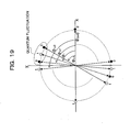
- the Y-00 scheme quantum cryptography is quantum cipher communication using a number of quantum states in a quantum-mechanically non-orthogonal state as a multi-valued signal.
- Coherent light beams arranged with adjoining phase angles are assigned with plain text of one bit "0” and plain text of one bit “1” by turns.
- the coherent light beams arranged at phase angles ⁇ i-1 , ⁇ i , ⁇ i+1 , and ⁇ i+2 are assigned with plain text "0” , "1", "0", "1", ⁇ , respectively.
- the interval of arrangement of phase multilevel signals is designed so that coherent light beams the phase angles of which are close cannot be distinguished from each other due to quantum fluctuation (coherent noise) by performing multilevel phase modulation of about 200 levels.
- the interval of arrangement of phase multilevel signals is designed so that the two coherent light beams arranged at adjoining phase angles ⁇ i-1 , ⁇ i+1 , respectively, are within quantum fluctuation by performing multilevel phase modulation of the coherent light with phase angle ⁇ i .
- coherent light beams 180 degrees different in phase angle from each other are assigned with plain text with inverted bits.
- the coherent light beam at a phase angle of 0 degree is assigned with plain text of one bit "0”
- the coherent light beams at a phase angle of 180 degrees is assigned with plain text of one bit "1”.
- which one of sets is used to express plain text of one bit is determined using a pseudo random number with which a transmitter side and a receiver side are synchronized and the pseudo random number is switched to another one for each communication of plain text of one bit.
- the respective coherent light beams at the phase angles ⁇ i-1 , ⁇ i , ⁇ i+1 , ⁇ i+2 , ⁇ are assigned with plain text "0", “1", “0”, “1”, ⁇ , and the coherent light beams 180 degrees different in phase angle from each other, that is, the respective coherent light angles at the phase angles ⁇ i-1 +180°, ⁇ i +180°, ⁇ i+1 +180°, ⁇ i+2 +180°, ⁇ , are assigned with plain text "1", "0", "1", "0", ⁇ .
- N (N is even) of the coherent light beams different in phase angle to one another are set, N/2 of sets of coherent light beams 180 degrees different in phase angle are set, as a result, and a value among N/2 of integer values, for example, among 0 to (N/2-1), is generated as a pseudo random number.
- the set of coherent light beams as the phase angles ⁇ i and ⁇ i +180° is selected and multilevel phase modulation of the coherent light beam at a phase angle of ⁇ i is performed so that the coherent light beams at a phase angle of ⁇ i and the adjoining coherent light beams as phase angles of ⁇ i-1 and ⁇ i+1 are within quantum fluctuation, and thus an optical signal after multilevel phase modulation is transmitted.
- the reception side knows which set of coherent light beams is used using the pseudo random number synchronized with the transmission side, therefore, it is possible to judge whether the plain text is "1" or "0" by discriminating the two states 180 degrees different in phase angle.
- the reception side receives a light signal having been subjected to multilevel phase modulation so that the coherent light beam at the phase angle ⁇ i and the coherent light beams at the phase angles ⁇ i-1 and ⁇ i+1 are within the quantum fluctuation, it is necessary for the interceptor to discriminate between the coherent light beams at the phase angles ⁇ i-1 , ⁇ i , and ⁇ i+1 (coherent light beams with small discrimination distance), therefore, decoding is impossible.
- DSR Deliberate Signal Randomization
- the above-mentioned scheme cannot be used with electric signals or electromagnetic waves because it uses a quantum-mechanical communication medium.
- a scheme called classic Y-00 scheme that performs such cryptography in a classic physical system has been researched in Tamagawa University etc.
- Non-patent document 2 O. Hirota, K. Kato, M. Sohma, T. Usuda, K. Harasawa, "Quantum stream cipher based on optical communications", Proc. On Quantum communication and quantum imaging, Proc. of SPIE, vol-5551, pp206-219,2004
- the applicants of the present invention have proposed a technique having a far greater encryption strength than conventional mathematical encryption by using the classic pseudo random number instead of quantum fluctuation in the Yuen quantum cryptography scheme and capable of realizing the classic Yuen cryptography applicable to a variety of media (refer to Japanese Patent Application No. 2005-276117 ).
- this technique the output of multilevel modification by a pseudo random number is further subjected to modulation in which a discrete DSR technique by a physical random number is performed, therefore, a discrete signal output is obtained and thus it is made possible to perform desired channel coding.
- the classic Y-00 scheme encryption has been proposed, which has a far greater encryption strength than the conventional mathematical encryption and capable of being stored as data in electric memories and a variety of recording media that can be used in electromagnetic wave communication and electrical communication and further capable of minimizing the influence on the communication rate without being influenced by noises.
- the applicants of the present invention have newly developed an encryption/cryptogram decoding technique applicable to a variety of media and having a far greater encryption strength than the conventional mathematical encryption (the same encryption strength as that of the above-mentioned classic Y-00 scheme cryptography) by using a method different from the above-mentioned classic Y-00 scheme cryptography.
- an encryption method of the present invention is characterized by comprising:
- an encryption method of the present invention is characterized by comprising a modulation step for modulating one-bit input data into a coded signal by associating the one-bit input data with a discrete value determined by a pseudo random number and a physical random number and for generating the discrete value as the coded signal, wherein:
- a second pseudo random number generated based on an encryption key periodically or non-periodically changed to a value determined by a physical random number may be used as the physical random number.
- a cryptogram decoding method of the present invention is characterized by comprising a demodulation step for demodulating a coded signal, the coded signal being obtained by performing modulation to associate one-bit input data with a discrete value determined by a pseudo random number and a physical random number, the modulation premising that:
- the pseudo random number generation section, the physical random number generation section, and the modulation section may be arranged in a tamper-resistant region for suppressing the probability distribution variations by physical disturbance in the physical random number generated by the physical random number generation section as well as suppressing the leakage of the encryption key and the pseudo random number, or the pseudo random number generation section may be configured so as to prohibit reset and repetition of the pseudo random number generation operation.
- the encryptor of the present invention may comprise:
- an encryption method of the present invention is characterized by comprising a modulation step for modulating one-bit input data into a coded signal by associating the one-bit input data with a discrete value determined by a pseudo random number and a physical random number and for generating the discrete value as the coded signal, wherein:
- the encryption method of the present invention may be one in which:
- the encryption method of the present invention may be one in which:
- a cryptogram decoder of the present invention is characterized by demodulating a coded signal, the coded signal being obtained by performing modulation to associate one-bit input data with a discrete value determined by a pseudo random number and a physical random number, the modulation premising that:
- the demodulation pseudo random number generation section and the demodulation section may be arranged in a tamper-resistant region for preventing leakage of the encryption key and the demodulation pseudo random number, or the demodulation pseudo random number generation section may be configured so as to prohibit reset and repetition of the demodulation pseudo random number generation operation.
- the cryptogram decoder of the present invention may comprise:
- the serial number or the number of output times may be included in the coded signal in the container section of each packet to be transmitted from the encryptor to the cryptogram decoder and the cryptogram decoder may comprise:
- a pseudo random number sequence generated by the pseudo random number generation section may be included as an intrinsic authentication code about the packet in the coded signal in the container section of each packet to be transmitted from the encryptor to the cryptogram decoder and the cryptogram decoder may comprise:
- the discrete DSR technique using a physical random number is performed and a discrete signal output of two bits can be obtained, therefore, it is made possible to perform desired channel coding and because of this, it is possible to provide an encryption/cryptogram decoding technique having a far greater encryption strength than the conventional mathematical encryption (the same encryption strength as that of the above-mentioned classic Y-00 scheme cryptography) and capable of being stored as data in electric memories and a variety of recording media that can be used in electromagnetic wave communication and electrical communication and further of minimizing the influence on the communication rate without being influenced by noises.
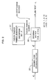
- Fig. 1 is a block diagram showing a configuration of an encryptor as a first embodiment of the present invention and as shown in Fig. 1, an encryptor 10 in the first embodiment is configured so as to provide a pseudo random number generator 11, a physical random number generator 12, a modulation section 13, and a channel coding section 14.
- the pseudo random number generator (first pseudo random number generation section, modulation pseudo random number generation section) 11 generates and outputs a modulation pseudo random number (first pseudo random number) r i based on an encryption key K set in advance.
- a modulation pseudo random number first pseudo random number
- the output from the physical random number generator 11 is dealt with as a pseudo random number r i .
- the pseudo random number r i has four integers 0, 1, 2, and 3 as its state. In other words, r i ⁇ 0, 1, 2, 3 ⁇ .
- the physical random number generator (physical random number generation section) 12 generates a physical random number f i based on a physical phenomenon.
- a physical phenomenon an essentially random phenomenon such as noises in the natural world, cosmic rays, thermal fluctuation (thermal noises), and decay of radioactive isotopes is used and by using such a physical phenomenon, it is possible for the physical random number generator 12 to generate a random number sequence that requires no encryption key, having no reproductivity or periodicity, and which cannot be predicted.
- the output from the physical random number generator 12 is dealt with as the physical random number f i .
- the physical random number f i has two integers 0 and 1 as its state. In other words, f i ⁇ 0, 1 ⁇ .
- the modulation section 13 modulates plain text x i as binary number input data by associating the plain text with a two-bit discrete value determined by a modulation pseudo random number r i generated by the pseudo random number generator 11 and a physical random number f i generated by the physical random number generator 12 and outputs as modulation output s i .
- the modulation output s i is dealt with an output of a modulation three-variable function the variables of which being the plain text x i , the pseudo random number r i , and the physical random number f i .
- the modulation three-variable function associates the plain text x i , the pseudo random number r i , and the physical random number f i with the output s i based on the encode table to be described later with reference to Fig. 5 to Fig. 7 and sets a correspondence relationship between the plain text x i , the pseudo random number r i , the physical random number f i , and the output s i so that all of the conditions in the following items [I], [II], and [III] are met simultaneously.
- the output (discrete value) s i has four integer values 0, 1, 2, and 3 as its state. In other words, s i ⁇ 0, 1, 2, 3 ⁇ .
- the modulation by the modulation section 13 be such one that the modulation output is a discrete multilevel signal with four levels, therefore, digital modulation such as intensity modulation, phase modulation, and PCM (Pulse Code Modulation) can be used regardless of its modulation scheme.
- An input signal of modulation and an output signal of modulation can also be used as long as they are a signal that can be expressed by a discrete value such as an intensity signal, a phase signal, a digital signal, a parallel signal using plural signal lines, and a serial signal to be time sequential data regardless of the type of the signal.
- the channel coding section 14 performs desired channel coding suited to the communication channel of the output s i of the modulation section 13 and outputs its output s i as cipher text (encrypted data) c i .
- the output s i is converted into a binary number.
- coding by error correction code is performed in order to add resistance to the errors in the communication channel and a series of coding processing such as processing for improving use efficiency of the code is performed if necessary. Examples of error correction code include hamming code, Reed-Solomon code, LDPC (Low Density Parity Check) code, turbo code, etc.
- the operation of the channel coding section 14 is expressed by identity mapping and at this time, the channel coding section 14 can be omitted.
- Fig. 2 is a block diagram showing a configuration of a cryptogram decoder as a first embodiment of the present invention and as shown in Fig. 2, a cryptogram decoder 20 in the present embodiment decodes cipher text c i obtained by the encryptor 10 described above and is configured so as to provide a pseudo random number generator 21, a demodulation section 22, and a channel decoding section 23.
- the channel decoding section 23 channel-decodes cipher text c i obtained by the encryptor 10 and obtains a decoded signal d i .
- the decoded signal d i and the output s i of the modulation section 13 of the encryptor 10 corresponding to the same plain text x i are equal.
- the operation of the channel decoding section 23 when using the demodulation section 22 capable of directly demodulating cipher text c i is expressed by identity mapping and at this time, the channel decoding section 23 can be omitted.
- the pseudo random number generator (pseudo random number generation section, demodulation pseudo random number generation section) 21 generates and outputs, based on the same encryption key K as the encryption key K having generated the pseudo random number r i used in the modulation by the modulation section 13 in the encryptor 10, a demodulation pseudo random number r i in synchronization with the modulation pseudo random number r i and has the same configuration as that of the pseudo random number generator 11 in the encryptor 10.
- the demodulation section 22 demodulates the decoded signal d i obtained by the channel decoding section 23 into the plain text x i as input data by the pseudo random number r i generated by the pseudo random number generator 21 and in the present embodiment, is designed so as to demodulate the decoded signal d i into the plain text x i by associating the decoded signal d i and the pseudo random number r i with the plain text x i based on the decode table, which will be described later with reference to Fig. 6 (B) or Fig. 7(B).
- the plain text x i is dealt with as the output of the demodulation two-variable function with the decoded signal d i and the pseudo random number r i being as variables.
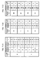
- Fig. 3 shows an example of the 2-2-2 type modulation three-variable function (encode table) the configuration of which is smaller than that of the 4-2-4 type, that is, an example of the modulation three-variable function (encode table)
- s i M (x i , r i , f i ) when the number of states of the pseudo random number r i is 2 and the number of states of the physical random number f i is 2 and the number of states of the modulation output s i is 2.
- r i ⁇ 0, 1 ⁇ , f i ⁇ 0, 1 ⁇ , and s i ⁇ 0, 1 ⁇ .
- examples (1) to (3) of the output (discrete value) s i are shown for the four kinds of set of the pseudo random number r i and the physical random number f i when the plain text x i is "0" and the four kinds of set of the pseudo random number r i and the physical random number f i when the plain text x i is "1", that is, in total, for the eight kinds of set of x i , r i , and f i .
- the 2-2-2 type modulation three-variable function (encode table) s i M (x i , r i , f i ) capable of realizing mapping that simultaneously meets all of the conditions in the above-mentioned items [I], [II], and [III] does not exist.
- Fig. 4 shows an example of the 2-2-4 type modulation three-variable function (encode table) the configuration of which is smaller than that of the 4-2-4 type and larger than that of the 2-2-2 type, that is, an example of the modulation three-variable function (encode table)
- s i M (x i , r i , f i ) when the number of states of the pseudo random number r i is 2 and the number of states of the physical random number f i is 2 and the number of states of the modulation output s i is 4.
- r i ⁇ 0, 1 ⁇ , f i ⁇ 0, 1 ⁇ , and s i ⁇ 0, 1, 2, 3 ⁇ .
- examples (1) to (5) of the output (discrete value) s i are shown for the four kinds of set of the pseudo random number r i and the physical random number f i when the plain text x i is "0" and the four kinds of set of the pseudo random number r i and the physical random number f i when the plain text x i is "1", that is, in total, for the eight kinds of set of x i , r i , and f i .
- the 2-2-4 type modulation three-variable function (encode table) s i M (x i , r i , f i ) capable of realizing mapping that simultaneously meets all of the conditions in the above-mentioned items [I], [II], and [III] does not exist.
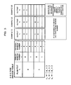
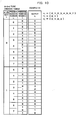
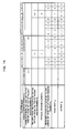
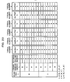
- Fig. 5 shows an example of the 4-2-4 type modulation three-variable function (encode table), that is, an example of the modulation three-variable function (encode table)
- s i M (x i , r i , f i ) when the number of states of the pseudo random number r i is 4 and the number of states of the physical random number f i is 2 and the number of states of the modulation output s i is 4.
- r i 0, 1, 2, 3 ⁇ , f i ⁇ 0, 1 ⁇
- s i ⁇ 0, 1, 2, 3 ⁇ .
- examples (1) to (7) of the output (discrete value) s i are shown for the eight kinds of set of the pseudo random number r i and the physical random number f i when the plain text x i is "0" and the eight kinds of set of the pseudo random number r i and the physical random number f i when the plain text x i is "1", that is, in total, for the 16 kinds of set of x i , r i , and f i .
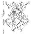
- Fig. 8 schematically shows a correspondence relationship between the plain text x i , the pseudo random number r i , the physical random number f i , and the output s i as to the example (1) of the output s i shown in Fig. 5, that is, as to the encode table shown in Fig. 6(A). As shown in Fig. 8, according to the encode table shown in Fig.
- the number of cases where the plain text x i corresponding to the output s i is "1" and the number of cases where that is "0" are equal and every correspondence relationship of the pseudo random number r i and the physical random number f i between the plain text x i and the output s i is distributed evenly (refer to the lines L0000, L0011, L0101, L0110, L0202, L0213, L0303, L0312, L1002, L1013, L1103, L1112, L1200, L1211, L1301, and L1310), and if the physical random number f i and the pseudo random number r i are random, the states of the output s i are distributed also randomly.
- Fig. 9 schematically shows a correspondence relationship between the plain text x i , the pseudo random number r i , the physical random number f i , and the output s i as to the example (7) of the output s i shown in Fig. 5, that is, as to the encode table shown in Fig. 7 (A).
- the number of cases where the plain text x i corresponding to the output s i is "1" and the number of cases where that is "0" are equal like the example shown in Fig.
- some of the setting patterns (the output s i for the set of x i , r i , f i ) possible with the 4-2-4 type may not meet one or two or more of the conditions in the above-mentioned items [I] to [III] as shown in the examples (3) to (5) of the output s i shown in Fig. 5, however, as the examples (1), (2), (6), and (7) of the output s i shown in Fig.
- the 23,040 encode tables there exist six typical elements (encode tables) and it is possible to completely express 23,040 equivalent patterns by performing replacement of the values of the pseudo random number r i and further performing replacement of the values of the physical random number f i as to the relationship between the pseudo random number r i , the physical random number f i , and the output s i of the respective typical elements.
- each S' j in which such replacements are performed as an equivalent encode table that satisfies all of the conditions in the above-mentioned items [I] to [III].
- each S' j replacement of physical random number f 0,i with physical random number f 1,i and replacement of physical random number f 10,i with physical random number f 11,i are performed and replacement is not performed for other physical random numbers as a result, therefore, it is also possible to use each S" j in which such replacements are performed as an equivalent encode tabel that satisfies all of the conditions in the above-mentioned items [I] to [III].
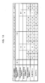
- r i ⁇ 0, 1, 2, 3, 4, 5, 6, 7 ⁇ , f i ⁇ 0, 1 ⁇ , and s i ⁇ 0, 1, 2, 3 ⁇ .
- the example (1) of the output (discrete value) s i is shown for 16 sets of pseudo random number r i and physical random number f i in the case where plain text x i is "0" and 16 sets of pseudo random number r i and physical random number f i in the case where plain text x i is "1", that is, for 32 sets in total of x i , r i , and f i .
- the physical random number f i is "1", however, there is the possibility that the physical random number f i may be "0" in addition to "1".
- the output s i of the modulation section 13 is given an irregular association using the physical random number f i while maintaining a situation in which the state of the plain text x i can be judged on the side of a legitimate receiver and the output s i of the modulation section 13 channel-coded by the channel coding section 14 is the cipher text c i .
- a cryptogram decoding procedure operation of the cryptogram decoder 20 in the first embodiment, more specifically, a cryptogram decoding procedure in the case where the cipher text c i of the plain text x i one bit is decoded using the decode table shown in Fig. 7(B) will be explained.
- the demodulation pseudo random number r i in synchronization with the modulation pseudo random number r i is output based on the same encryption key K as the encryption key K having generated the modulation pseudo random number r i in the encryptor 10 by the pseudo random number generator 21.
- the legitimate receiver side when receiving the cipher text c i corresponding to plain text one bit, the legitimate receiver side obtains a decoded signal d i by channel-decoding the cipher text c i with the channel decoding section 23 and at the same time, in synchronization with the reception timing, the demodulation pseudo random number r i in the same state as that of the modulation pseudo random number r i used when the cipher text c i was encrypted is generated and output by the pseudo random number generator 21, the plain text x i is obtained as the value of the demodulation two-variable function D (d i , r i ) in accordance with the decode table shown in Fig. 7(B), and the decoded signal d i is demodulated into the plain text x i .
- the output s i of the modulation section 13 is given an irregular association by physical random number f i and as described above, it is made possible for the legitimate receiver side to demodulate the decoded signal d i using only the pseudo random number r i without using the physical random number f i while guaranteeing a high safety capable of securing an extremely high encryption strength against not only the cipher text only attack but also the known plain text attack.
- the encryption technique in the present embodiment is realized by code (simple numerical values), different from the Y-00 scheme quantum cryptography, therefore, like the case of the already existing classic encryption, it is possible to transfer cipher text by means of electromagnetic waves or electric line and it is made possible to use cipher text in radio communication or electrical communication and, in addition, it is also made possible to store the cipher text c i in an electric memory or a variety of recording media (flexible disc, CD, DVD, etc.) Further, the cipher text c i can be stored in an electric memory, therefore, it is made possible to pass the cipher text c i through a router.
- the encryption technique in the present embodiment is realized by code (simple numerical values), therefore, it is not necessary to transmit and receive many physical states that are unstable like the Y-00 scheme quantum cryptography and it is unlikely to receive the influence of noises, and when the present encryption technique is used in optical communication, a light amplifier with low noise is no longer necessary and the number of relay stages is not restricted by the noise level of the light amplifier and, in addition, the development of a light source with excellent linearity and a light receiving device is also no longer necessary.
- the encryption technique in the present embodiment even if the number of states of the pseudo random number r i used in modulation is 4, a sufficiently high safety can be guaranteed, therefore, the number of states can be reduced considerably compared to the Y-00 scheme quantum cryptography that requires about 200 of states of a multilevel signal and it is possible to minimize the influence of the operation rate of the pseudo random number generators 11 and 21 on the communication rate by suppressing the number of bits of the pseudo random number r i .
- the modulation output s i per one bit of the plain text to be transmitted is two bits and thus the transfer efficiency is improved considerably.
- the stream cipher is vulnerable to a known plain text attack, therefore, it is necessary to frequently distribute and change the encryption key between the encryption side (the legitimate transmitter side) and the cryptogram decoding side (the legitimate receiver side) using the public key encryption.
- the safety of the public key encryption is based on only the fact that the algorithm for performing the prime factorization at high speed has not been discovered until now and once a calculation method for performing the prime factorization is discovered, the encryption key is decoded extremely easily. Because of this, it has been desired to obviate the need to perform distribution of the encryption key using the public key encryption.
- the pseudo random number generator including the encryption key K when the pseudo random number generator including the encryption key K is embedded, it is preferable to construct a structure having tamper-resistant properties by configuring at least a chip including a memory that stores the encryption key K into a state in which the encryption key K cannot be read from the outside in order to secure the safety by preventing the encryption key K from being read by not only the user but also an illegitimate person who accesses (an interceptor).
- a structure having tamper-resistant properties for example, a memory chip the recorded contents of which become extinct when the chip surface is exposed to air or a circuit that functions no longer if a probe to read a signal is attached thereto is used.
- the encryption/cryptogram decoding technique as the second embodiment of the present invention to be explained below with reference to Fig. 11 to Fig. 16 is a combination of the encryption/cryptogram decoding technique described above as the first embodiment with reference to Fig. 1 to Fig. 10 and the stream cipher scheme described above as the prior art with reference to Fig. 18, and in the second embodiment, it is so configured that the plain text x i is modulated into a nine-bit output s i for each of the eight bits.
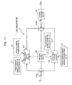
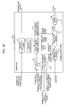
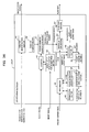
- Fig. 11 is a block diagram showing the configuration of the encryptor as the second embodiment of the present invention and as shown in Fig. 11, an encryptor 10A in the second embodiment comprises the pseudo random number generator 11, the physical random number generator 12, the modulation section 13, and the channel coding section 14, like those in the first embodiment and at the same time, further comprises pseudo random number generators 11' and 11", a modulation section 15, a switching control section 16 and switches 17a and 17b.
- pseudo random number generators 11' and 11 a modulation section 15 a switching control section 16 and switches 17a and 17b.
- the pseudo random number generator 11 in the second embodiment generates and outputs a modulation pseudo random number r i based on the encryption key K set in advance like the first embodiment, however, in the second embodiment, it is configured so as to generate and output two bits of the pseudo random number r i for eight-bit plain text x i .
- the pseudo random number generator (pseudo random number generation section, modulation pseudo random number generation section) 11' generates and outputs a modulation pseudo random number r i ' based on the encryption key K' set in advance.
- the encryption key K' is, for example, a 100-bit binary number
- a (2 100 -1)-bit binary number that is, a pseudo random number with a period of (2 100 -1) bits is generated from the pseudo random number generator 11'.
- the output from the pseudo random number generator 11' is dealt with as the pseudo random number r i ' and the pseudo random number r i ' is used in modulation (into stream cipher) in the modulation section 15 to be described later.
- seven bits of the pseudo random number r i ' are generated and output for the eight-bit plain text x i .
- the pseudo random number generator (pseudo random number generation section, modulation pseudo random number generation section) 11" generates and outputs a modulation pseudo random number r i " based on the encryption key K" set in advance.
- the encryption key K is, for example, a 100-bit binary number
- a (2 100 -1)-bit binary number that is, a pseudo random number with a period of (2 100 -1) bits is generated from the pseudo random number generator 11".
- the output from the pseudo random number generator 11" is dealt with as the pseudo random number r i " and the pseudo random number r i " is used for the switching control by the switching control section 16, which will be described later.
- the pseudo random number r i " has eight integer values 0, 1, 2, 3, 4, 5, 6, and 7 as its state. In other words, r i " ⁇ 0, 1, 2, 3, 4, 5, 6, 7 ⁇ .
- the modulation section (eXclusive OR arithmetic unit) 15 performs the same function as that of the modulation section 112 shown in Fig. 18 and calculates an XOR (eXclusive OR) of the plain text x i to be modulated and the pseudo random number r i ' generated by the pseudo random number generator 11' and outputs it as a modulation result.
- the plain text x i is modulated by the modulation section 15 based on the pseudo random number r i ' and output as the modulation result s i .
- the switch 17a inputs the plain text x i to be transmitted by selectively switching to either of the modulation section 13 and the modulation section 15, the switch 17b selectively switches to input either of the modulation result from the modulation section 13 and the modulation result from the modulation section 15 to the channel coding section 14 as the output s i , and the switching control section 16 controls the switches 17a and 17b to switch to either of the modulation section 13 side and the modulation section 15 side in accordance with the pseudo random number r i " generated by the pseudo random number generator 11".
- the switching control section 16 deals with the eight-bit plain text x i as one block, receives the pseudo random number r i " from the pseudo random number generator 11" and, as will be described later with reference to Fig. 13, regards the state value (0 to 7) of the pseudo random number r i " as one of the slot numbers in the above-mentioned block, and switches the switch 17a to the modulation section 13 side so as to input the one-bit plain text x i corresponding to the slot number (state value) to the modulation section 13 and at the same time, switches the switch 17b to the modulation section 13 side so as to input the modulation result by the modulation section 13 for the one-bit plain text x i to the channel coding section 14 as the output s i , and on the other hand, switches the switch 17a to the modulation section 15 side so as to input the seven-bit plain text x i other than the above-mentioned slot number (state value) to the modulation section 15 and at the same time, switches
- modulation is performed by the modulation section 13 for one bit among the eight-bit plain text x i
- modulation is performed by the modulation section 15 for the other seven bits
- the eight-bit plain text x i is modulated into a nine-bit output s i and output.
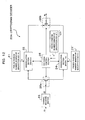
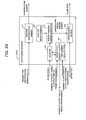
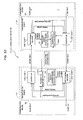
- Fig. 12 is a block diagram showing the configuration of the cryptogram decoder as the second embodiment of the present invention and as shown in Fig. 12, a cryptogram decoder 20A in the second embodiment comprises the pseudo random number generator 21, the demodulation section 22, and the channel decoding section 23, like those in the first embodiment and at the same time, further comprises pseudo random number generators 21' and 21", a demodulation section 24, a switching control section 25 and switches 26a and 26b.
- the same symbols as those already described denote the same or substantially the same portions, therefore, their detailed explanation is omitted.
- the pseudo random number generator 21 in the second embodiment like the first embodiment, generates and outputs the demodulation pseudo random number r i in synchronization with the modulation pseudo random number r i based on the same encryption key K as the encryption key K having generated the pseudo random number r i used in the modulation by the modulation section 13 in the encryptor 10A and has the same configuration as the pseudo random number generator 11 in the encryptor 10A, and is configured so as to generate and output two bits of the pseudo random number r i for the nine-bit decoded signal d i .
- the pseudo random number generator (pseudo random number generation section, demodulation pseudo random number generation section) 21' generates and outputs the demodulation pseudo random number r i ' in synchronization with the modulation pseudo random number r i ' based on the same encryption key K' as the encryption key K' having generated the pseudo random number r i ' in the encryptor 10A and has the same configuration as the pseudo random number generator 11' in the encryptor 10A, and is configured so as to generate and output seven bits of the pseudo random number r i ' for the 9-bit decoded signal d i .
- the pseudo random number generator (pseudo random number generation section, demodulation pseudo random number generation section) 21" generates and outputs the demodulation pseudo random number r i " in synchronization with the modulation pseudo random number r i " based on the same encryption key K" as the encryption key K" having generated the pseudo random number r i " in the encryptor 10A and has the same configuration as the pseudo random number generator 11" in the encryptor 10A, and is configured so as to generate and output three bits of the pseudo random number r i " for the 9-bit decoded signal d i .
- the pseudo random number r i " is used for the switching control by the switching control section 25, which will be described later.
- the pseudo random number r i " is used only to determine once the timing (the two-bit decoded signal d i to be demodulated by the demodulation section 22) at which the switches 26a and 26b are switched to the demodulation section 22 side by the switching control section 25 for each nine-bit decoded signal d i (one block), which will be described later.
- the demodulation section (exclusive OR arithmetic unit) 24 performs the same function as that of the demodulation section 122 shown in Fig. 18 and calculates an XOR of the decoded signal d i to be demodulated and the pseudo random number r i ' generated by the pseudo random number generator 21' and outputs it as the plain text x i .
- the decoded signal d i is demodulated by the demodulation section 24 based on the pseudo random number r i ' and its demodulation result is output as the plain text x i .
- the switch 26a inputs the decoded signal d i obtained by the channel decoding section 23 by selectively switching to either of the demodulation section 22 and the demodulation section 24, the switch 26b selectively switches to output either of the demodulation result from the demodulation section 22 and the demodulation result from the demodulation section 24 as the plain text x i , and the switching control section 25 controls the switches 26a and 26b to switch to either of the demodulation section 22 side and the demodulation section 24 side in accordance with the pseudo random number r i " generated by the pseudo random number generator 21".
- the switching control section 25 deals with the nine-bit decoded signal d i as one block, receives the pseudo random number r i " from the pseudo random number generator 21", and regards the state value (0 to 7) of the pseudo random number r i " as one of the slot numbers in the above-mentioned block, and switches the switch 26a to the demodulation section 22 side so as to input the one-bit corresponding to the slot number (state value) and the next bit, that is, the two-bit decoded signal d i to the demodulation section 22 and at the same time, switches the switch 26b to the demodulation section 22 side so as to output the demodulation result by the demodulation section 22 for the two-bit decoded signal d i as the plain text x i , and on the other hand, switches the switch 26a to the demodulation section 24 side so as to input the seven-bit decoded signal d i other than the above-mentioned two bits to the demodulation section 24 and at the
- demodulation is performed by the demodulation section 22 for the two bits among the nine-bit decoded signal d i
- demodulation is performed by the demodulation section 24 for the other seven bits
- the nine-bit decoded signal d i is demodulated into the eight-bit plain text x i and output.
- a decoded signal d i is obtained by channel-decoding the cipher text c i with the channel decoding section 23 and at the same time, in accordance with the reception timing, the demodulation pseudo random numbers r i , r i ' , r i " in the same state as the modulation pseudo random numbers r i , r i ' , r i " used when encrypting the cipher text c i are generated and output by the pseudo random number generators 21, 21', and 21".
- the encryption/cryptogram decoding technique described above as the first embodiment with reference to Fig. 1 to Fig. 10 and the stream cipher scheme described above as the prior art with reference to Fig. 18 are combined and the eight-bit plain text x i is modulated into the nine-bit output s i and the nine-bit decoded signal d i is demodulated into the eight-bit plain text x i .
- the modulation output s i per plain text one bit to be transmitted is two bits, however, in the second embodiment, the eight-bit plain text x i is modulated into the nine-bit output s i , therefore, transfer efficiency is further improved considerably compared to the first embodiment.
- the encryptor 10 in the first embodiment it is necessary to generate a one-bit physical random number f i for one-bit plain text x i by the physical random number generator 12, therefore, it is necessary to use the physical random number generator 12 capable of high speed operation, however, for the encryptor 10A in the second embodiment, it is only necessary to generate a one-bit physical random number f i for eight-bit plain text x i , therefore, it is possible to use one with lower speed operation than that in the first embodiment as the physical random number generation section 12 in the second embodiment.
- a physical random number generator capable of high speed operation is expensive, however, a physical random number generator that operates at low speed is inexpensive, therefore, it is possible to configure the encryptor 10A in the second embodiment at a lower cost than that of the encryptor 10 in the first embodiment.
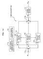
- Fig. 14 is a block diagram showing a configuration of a modification example of the encryptor in the second embodiment (the encryptor 10B)
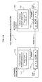
- Fig. 15 is a block diagram showing a configuration of a modification example of the cryptogram decoder in the second embodiment (the cryptogram decoder 20B)
- Fig. 16 is a diagram for specifically explaining the encryption operation by the encryptor 10B shown in Fig. 14.
- the encryptor 10B is provided with one pseudo random number generator 11a instead of the three pseudo random number generators 11, 11', and 11" of the encryptor 10A shown in Fig. 11.
- the pseudo random number generator (pseudo random number generation section, modulation pseudo random number generation section) 11a generates and outputs a 12-bit modulation pseudo random number R i for each eight-bit plain text x i (one block) based on the encryption key Ka set in advance.
- the encryption key Ka is, for example, a 100-bit binary number
- a (2 100 - 1) -bit binary number that is, a pseudo random number with a period of (2 100 - 1) bits is generated by the pseudo random number generator 11a.
- the three bits from the first bit to the third bit from the top are input to the switching control section 16 as a pseudo random number r i "
- the two bits from the fourth bit to the fifth bit from the top are input to the modulation section 13 as a pseudo random number r i
- the seven bits from the sixth bit to the lowest order bit from the top are input to the modulation section 15 as a pseudo random number r i '.
- the cryptogram decoder 20B comprises one pseudo random number generator 21a instead of the three pseudo random number generators 21, 21', and 21" of the cryptogram decoder 20A shown in Fig. 12.
- the pseudo random number generator (pseudo random number generation section, demodulation pseudo random number generation section) 21a generates and outputs the demodulation pseudo random number R i in synchronization with the modulation pseudo random number R i based on the same encryption key Ka as the encryption key Ka having generated the pseudo random number R i in the encryptor 10B and has the same configuration as the pseudo random number generator 11a in the encryptor 10B, and is configured so as to generate and output 12 bits of the pseudo random number R i for the nine-bit decoded signal d i .
- the cryptogram decoder 20B like the 12-bit modulation pseudo random number R i in the encryptor 10B, among the 12-bit modulation pseudo random number R i generated by the pseudo random number generator 21a, the three bits from the first bit to the third bit from the top are input to the switching control section 25 as a pseudo random number r i ", the two bits from the fourth bit to the fifth bit from the top are input to the demodulation section 22 as a pseudo random number r i , and the seven bits from the sixth bit to the lowest order bit from the top are input to the demodulation section 24 as a pseudo random number r i '.
- the same function and effect as those in the encryption/cryptogram decoding technique in the second embodiment described above are obtained and in addition, in the encryptor 10B and the cryptogram decoder 20B as a modification example, the pseudo random number generated by one of the pseudo random number generators 11a and 21a, respectively, is used as the three kinds of pseudo random numbers r i ", r i , and r i ', therefore, the configuration can be further simplified and at the same time, since the encryption key uses only one kind Ka, the management of the encryption key Ka becomes easy.
- the eight-bit plain text x i is regarded as one block and for each block, modulation by the modulation section 13 is performed for one bit among the eight-bit plain text x i , modulation by the modulation section 15 is performed for the other seven bits, and thus the eight-bit plain text x i is modulated into the nine-bit output s i , however, this is not limited.
- the switching control section 16 may also be possible for the switching control section 16 to control the switches 17a and 17b so that, for example, m-bit plain text (m is an integer greater than 1) is regarded as one block and for each block, modulation by the modulation section 13 is performed for the n bits (n is an integer not less than 1 and not greater than m-1) among the m-bit plain text x i , modulation by the modulation section 15 is performed for the other (m-n) bits, and the m-bit plain text x i is modulated into a (m+n)-bit output s i .
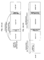
- Fig. 21 is a block diagram showing an entire configuration of a communication system 1 and 1A to which the encryption/cryptogram decoding technique as the third and fourth embodiments of the present invention has been applied, and the communication system 1 in the third embodiment shown in Fig. 21 comprises two communication devices 1a and 1b connected to each other so that communication is possible via a communication network etc.
- the communication system 1 in the third embodiment and the communication system 1A in the fourth embodiment to be described later a case where the two communication devices 1a and 1b are connected so that communication is possible by a communication channel (a signal line) without tampering and the two communication devices 1a and 1b perform synchronization processing by open communication will be explained.
- the communication devices 1a and 1b have the same configuration and the communication device 1a comprises an encryptor 10C for encrypting input data (plain text x i ) to be transmitted to the communication device 1b by the method described above in the first or second embodiment, a cryptogram decoder 20C for decoding the encrypted data (c i or s i ) received from the communication device 1b by the method described above in the first or second embodiment, and a transmission/reception section 52 and a synchronization adjustment section 53 to be described later, and the communication device 1b comprises the encryptor 10C for encrypting input data (plain text x i ) to be transmitted to the communication device 1a by the method described above in the first or second embodiment, the cryptogram decoder 20C for decoding the encrypted data (cipher text c i or s i ) received from the communication device 1a by the method described above in the first or second embodiment, and the transmission/reception section 52 and the synchronization adjustment section 53 to be described later.
- the encryptor 10C in the communication device 1a and the cryptogram decoder 20C in the communication device 1b are paired and the pseudo random number generators 11 and 21 in the devices 10C and 20C (refer to Fig. 22 and Fig. 23) are configured so as to synchronize and generate a pseudo random number r i based on the same encryption key.
- the encryptor 10C in the communication device 1b and the cryptogram decoder 20C in the communication device 1a are paired and the pseudo random number generators 11 and 21 in the devices 10C and 20C are also configured so as to synchronize and generate a pseudo random number r i based on the same encryption key.
- the encryption key used in each pair of devices described above different keys are set.
- the transmission data from the communication device 1a to the communication device 1b is encrypted by the above-mentioned encryption procedure by the encryptor 10C and transmitted to the communication device 1b as the cipher text and on the communication device 1b side, the cipher text received from the communication device 1a is decoded into plain text by the above-mentioned cryptogram decoding procedure by the cryptogram decoder 20C.
- the transmission data from the communication device 1b to the communication device 1a is encrypted by the above-mentioned encryption procedure by the encryptor 10C and transmitted to the communication device 1a as the cipher text and on the communication device 1a side, the cipher text received from the communication device 1b is decoded into plain text by the above-mentioned cryptogram decoding procedure by the cryptogram decoder 20C.
- the transmission/reception section 52 and the synchronization adjustment section 53 are used when synchronization shift occurs for some reason in the pseudo random number generation operation of the pseudo random number generators 11 and 21 and encryption communication between the encryptor 10C and the cryptogram decoder 20C becomes no longer possible.
- the transmission/reception section 52 transmits the number of output times of the modulation pseudo random number or the demodulation pseudo random number read from a nonvolatile memory 34 (refer to Fig. 22) or a nonvolatile memory 44 (refer to Fig. 23) to be described later to the communication device 1a or 1b, which is the other party of communication, as synchronization information and at the same time, receives synchronization information from the communication device 1a or 1b, which is the other party of communication.
- a general transceiver etc. that performs open communication is used.
- the above-mentioned number of output times is transmitted and received as synchronization information between the communication devices 1a and 1b (between the transmission/reception sections 52 and 52) via a network etc. (here, a communication channel without rewriting) using the transmission/reception sections 52 and 53 respectively provided to the communication devices 1a and 1b.
- the synchronization adjustment section 53 adjusts the numbers of output times of the pseudo random numbers from the pseudo random number generators 11 and 21 based on the numbers of output times read from the nonvolatile memory 34 or 44 in order to synchronize the pseudo random number generation operation by the modulation pseudo random number generator 11 (refer to Fig. 22) of the communication device 1a with the pseudo random number generation operation by the demodulation pseudo random number generator 21 (refer to Fig. 23) of the communication device 1b or in order to synchronize the pseudo random number generation operation by the modulation pseudo random number generator 11 (refer to Fig. 22) of the communication device 1b with the pseudo random number generation operation by the demodulation pseudo random number generator 21 (refer to Fig. 23) of the communication device 1a.
- the synchronization adjustment section 53 in the third embodiment adjusts to match the number of output times of the modulation pseudo random number from the pseudo random number generator 11 of the encryptor 10C (or the demodulation pseudo random number from the pseudo random number generator 21 of the cryptogram decoder 20C) with the number of output times of the demodulation pseudo random number (or the modulation pseudo random number) on the communication device 1a or 1b side of the other party of communication when the number of output times of the demodulation pseudo random number (or the modulation pseudo random number) on the communication device 1a or 1b side of the other party of communication, which is decoded by the transmission/reception section 52, is greater than the number of output times of the modulation pseudo random number (or the demodulation pseudo random number) read from the nonvolatile memory 34 (or 44).
- the synchronization adjustment section 53 in the third embodiment adjusts the number of output times from the pseudo random number generator 11 or 21 by setting the number of output times for the nonvolatile memory 34 of the encryptor 10C or the nonvolatile memory 44 of the cryptogram decoder 20C, or by performing dummy inputting of a clock signal for the pseudo random number generator 11 or 21.
- dummy inputting of a clock signal refers to an operation to input a clock signal for causing the pseudo random number generator 11 or 21 to perform the pseudo random number generation operation only to adjust the number of output times of pseudo random number without encrypting plain text.
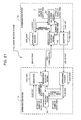
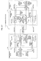
- Fig. 22 is a block diagram showing the configuration of the encryptor 10C as the third embodiment of the present invention and the encryptor 10C shown in Fig. 22 is configured so as to provide the modulation pseudo random number generator 11, the physical random number generator 12, and the modulation section 13 as those in the encryptor 10 in the first embodiment, and in addition, an identification number ROM (Read Only Memory) 31, an encryption key ROM (Read Only Memory) 32, a counter 33, and the nonvolatile memory 34.
- an identification number ROM Read Only Memory
- an encryption key ROM Read Only Memory
- the encryptor 10C in the present embodiment prevents leakage of the encryption key for pseudo random number generation or of the pseudo random number r i from the pseudo random number generator 11, and is arranged in a tamper-resistant region 60 for preventing probability distribution variations caused by physical disturbance in the physical random number f i generated by the physical random number generator 12.
- the tamper-resistant region 60 in which the encryptor 10C in the third embodiment is arranged provides such a structure like the following items (11) to (17).
- the encryptor 10C (the tamper-resistant region 60) shown in Fig. 22 is configured, for example, on a single chip (not shown).
- the channel coding section 14 (refer to Fig. 1, Fig. 11 and Fig. 14) is not shown schematically.
- the channel coding section 14 may be provided like the first and second embodiments or may not be provided.
- the channel coding section 14 may be arranged in the tamper-resistant region 60 or outside the tamper-resistant region 60.
- the modulation pseudo random number generator 11 in the third embodiment is configured so as to prohibit reset and repetition of the generation operation of the modulation pseudo random number r i .
- the pseudo random number generator 11 is configured so that "the reset (rewinding) of the pseudo random number output is possible in no case".
- the counter 33 and the nonvolatile memory 34 are so designed as to be capable of outputting "what number pseudo random number has been output" if there is a request from the outside.
- the modulation pseudo random number generator 11 in the third embodiment is capable of advancing the modulation pseudo random number r i (that is, the number of output times) one by one by performing dummy inputting of a clock signal and of generating and outputting a modulation pseudo random number r i from a desired number of output times (N-th) ahead of the current number of output times by setting a desired number of output times (for example, N) to the nonvolatile memory 34, which will be described later.
- N desired number of output times
- the identification number ROM 31 holds the identification number (ID number) inherent to the encryptor 10C and the identification number is output to the outside from the ROM 31 at the request for the output of the identification number from the outside.
- the identification number has no numerical relationship with the encryption key (seed) held in the encryption key ROM 32, however, it corresponds to the encryption key (seed) in a one-to-one manner and with this identification number, it is made possible to identify the cryptogram decoder 20C to be synchronized with the encryptor 10C, that is, the cryptogram decoder 20C holding the same encryption key (seed) as the encryption key (seed) held in the encryption key ROM 32 of the encryptor 10C.
- the encryption key ROM 32 holds the encryption key (seed) used in the modulation pseudo random number generator 11 and the modulation pseudo random number generator 11 in the third embodiment generates the modulation pseudo random number r i based on the encryption key (seed) held in the ROM 32.
- the counter 33 counts the number of input times of a clock signal input from the outside to cause the modulation pseudo random number generator 11 to perform the pseudo random number generation operation, that is, the number of output times of the modulation pseudo random number r i from the modulation pseudo random number generator 11.
- the nonvolatile memory (first hold section) 34 holds the number of output times (the number of input times of the clock signal) counted by the counter 33 and also has the function of outputting the held number of output times to the outside (outside the encryptor 10C/outside the tamper-resistant region 60) in response to an output command from the outside (outside the encryptor 10C/outside the tamper-resistant region 60).
- the nonvolatile memory 34 is configured so that a desired number of output times (for example, N) is set from the outside (outside the encryptor 10C/outside the tamper-resistant region 60) and when the number of output times is set to the nonvolatile memory 34, the number of output times is further set to the counter 33 from the nonvolatile memory 34.
- the modulation pseudo random number generator 11 is configured so as to generate a modulation pseudo random number r i from the N-th number corresponding to the number of output times set to the counter 33 based on the encryption key (seed) held in the encryption key ROM 32.
- the modulation pseudo random number generator 11 that generates a modulation pseudo random number r i from the N-th number corresponding to the number of output times set to the counter 33 based on the encryption key (seed) held in the encryption key ROM 32
- a BBS Blum, and Shub
- L. Blum, M. Blum, and M. Shub "A Simple Unpredictable Pseudo-Random Number Generator", SIAM Journal on Computing, v. 15, n.2, 1986, pp.364-383 ).
- this BBS generator it is possible to calculate the N-th modulation pseudo random number r i directly from the "seed" (encryption key).
- the modulation pseudo random number generator 11 is capable of sequentially generating the modulation pseudo random number r i each time a clock signal is input and in addition, of generating the N-th modulation pseudo random number r i directly from the encryption key (seed) held in the encryption key ROM 32 only by setting the number of output times N to the counter 33 (the nonvolatile memory 34).
- the number of output times of the modulation pseudo random number r i (the number of input times of the clock signal) from the modulation pseudo random number generator 11 is counted by the counter 33 at all times and recorded in the nonvolatile memory 34, therefore, even if the power of the encryptor 10C is cut off, when the power is turned on next time, the modulation pseudo random number generator 11 will start the output of the pseudo random number from one next to the pseudo random number output last before the power is cut off.
- the dummy inputting of a clock to the modulation pseudo random number generator 11 or setting of the number of output times to the nonvolatile memory 34 is performed at the request of a user at the time of initial setting and in addition, it is performed by the synchronization adjustment section 53 (refer to Fig. 21) in order to adjust the synchronization between the encryptor 10C and the cryptogram decoder 20C (to eliminate the synchronization shift that has occurred in the pseudo random number generation operation between the pseudo random number generators 11 and 21), as described above.
- the number of output times set to the nonvolatile memory 34 (the counter 33) by the input interface of the item (28) can be set at all times only in the direction of increment, however, it may also be possible to omit the input interface of the item (28) and perform the setting of the number of output times by performing dummy inputting of a clock signal for the counter 33/modulation pseudo random number generator 11.
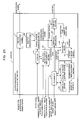
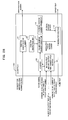
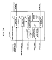
- Fig. 23 is a block diagram showing the configuration of the cryptogram decoder 20C as the third embodiment of the present invention and the cryptogram decoder 20C shown in Fig. 23 is configured so as to provide the demodulation pseudo random number generator 21 and the demodulation section 22 as those in the cryptogram decoder 20 in the first embodiment, and in addition, an identification number ROM (Read Only Memory) 41, an encryption key ROM (Read Only Memory) 42, a counter 43, and the nonvolatile memory 44.
- an identification number ROM Read Only Memory
- an encryption key ROM Read Only Memory
- the cryptogram decoder 20C in the present embodiment is arranged in the tamper-resistant region 60 for preventing leakage of the encryption key for pseudo random number generation or of the pseudo random number r i from the pseudo random number generator 11.
- the tamper-resistant region 60 in which the cryptogram decoder 20C in the third embodiment is arranged provides such a structure like the following items (31) to (35).
- the cryptogram decoder 20C (the tamper-resistant region 60) shown in Fig. 23 is configured, for example, on a single chip (not shown).
- the channel decoding section 23 is provided like the first and second embodiments if the channel coding section 14 is provided on the encryptor 10C side.
- the channel decoding section 23 may be arranged in the tamper-resistant region 60 or outside the tamper-resistant region 60.
- the demodulation pseudo random number generator 21 in the third embodiment is also configured so as to prohibit reset and repetition of the generation operation of the modulation pseudo random number r i , like the modulation pseudo random number generator 11 in the third embodiment.
- the pseudo random number generator 21 is configured so that "the reset (rewinding) of the pseudo random number output is possible in no case". Instead of this, in the present embodiment, if there is a request from the outside, "what number pseudo random number has been output" is output by the function of the counter 43 and the nonvolatile memory 44, which will be described later.
- the demodulation pseudo random number generator 21 in the third embodiment is also capable of advancing the demodulation pseudo random number r i (that is, the number of output times) one by one by performing dummy inputting of a clock signal and of generating and outputting a demodulation pseudo random number r i from a desired number of output times (N-th) ahead of the current number of output times by setting a desired number of output times (for example, N) to the nonvolatile memory 44, which will be described later.
- N desired number of output times
- the identification number ROM 41 holds the identification number (ID number) inherent to the cryptogram decoder 20C and the identification number is output to the outside from the ROM 41 at the request for the output of the identification number from the outside.
- the identification number has no numerical relationship with the encryption key (seed) held in the encryption key ROM 42, however, with this identification number, it is made possible to identify the encryptor 10C to be synchronized with the cryptogram decoder 20C, that is, the encryptor 10C holding the same encryption key (seed) as the encryption key (seed) held in the encryption key ROM 42 of the cryptogram decoder 20C.
- the encryption key ROM 42 holds the encryption key (seed) used in the demodulation pseudo random number generator 21 and the demodulation pseudo random number generator 21 in the third embodiment generates the demodulation pseudo random number r i based on the encryption key (seed) held in the ROM 42.
- the counter 43 counts the number of input times of a clock signal input from the outside to cause the demodulation pseudo random number generator 21 to perform the pseudo random number generation operation, that is, the number of output times of the demodulation pseudo random number r i from the demodulation pseudo random number generator 21.
- the nonvolatile memory (first hold section) 44 holds the number of output times (the number of input times of the clock signal) counted by the counter 43 and also has the function of outputting the held number of output times to the outside (outside the cryptogram decoder 20C/outside the tamper-resistant region 60) in response to an output command from the outside (outside the cryptogram decoder 20C/outside the tamper-resistant region 60).
- the nonvolatile memory 44 is configured so that a desired number of output times (for example, N) is set from the outside (outside the cryptogram decoder 20C/outside the tamper-resistant region 60) and when the number of output times is set to the nonvolatile memory 44, the number of output times is further set to the counter 43 from the nonvolatile memory 44.
- the demodulation pseudo random number generator 21 is configured so as to generate a demodulation pseudo random number r i from the N-th number corresponding to the number of output times set to the counter 43 based on the encryption key (seed) held in the encryption key ROM 42.
- a BBS generator is used like the modulation pseudo random number generator 11 in the third embodiment.
- the demodulation pseudo random number generator 21 is capable of sequentially generating the demodulation pseudo random number r i each time a clock signal is input and in addition, of generating the N-th demodulation pseudo random number r i directly from the encryption key (seed) held in the encryption key ROM 42 only by setting the number of output times N to the counter 43 (the nonvolatile memory 44).
- the number of output times of the demodulation pseudo random number r i (the number of input times of the clock signal) from the demodulation pseudo random number generator 21 is counted by the counter 43 at all times and recorded in the nonvolatile memory 44, therefore, even if the power of the cryptogram decoder 20C is cut off, when the power is turned on next time, the demodulation pseudo random number generator 21 will start the output of the pseudo random number from one next to the pseudo random number output last before the power is cut off.
- the dummy inputting of a clock to the demodulation pseudo random number generator 21 or setting of the number of output times to the nonvolatile memory 44 is performed at the request of a user at the time of initial setting etc. and in addition, it is performed by the synchronization adjustment section 53 (refer to Fig. 21) in order to adjust the synchronization between the encryptor 10C and the cryptogram decoder 20C (to eliminate the synchronization shift that has occurred in the pseudo random number generation operation between the pseudo random number generators 11 and 21), as described above.
- the number of output times set to the nonvolatile memory 44 (the counter 43) by the input interface of the item (48) can be set at all times only in the direction of increment, however, it may also be possible to omit the input interface of the item (48) and perform the setting of the number of output times by performing dummy inputting of a clock signal for the counter 43/demodulation pseudo random number generator 21.
- the encryptor 10C is configured similarly to the encryptor 10 shown in Fig. 1, however, it may also be configured so as to provide the same configuration as the encryptor 10A shown in Fig. 11 or the encryptor 10B shown in Fig. 14.
- the cryptogram decoder 20C is configured similarly to the encryptor 20 shown in Fig. 2, however, it may also be configured so as to provide the same configuration as the cryptogram decoder 20A shown in Fig. 12 or the cryptogram decoder 20B shown in Fig. 15.
- the communication system 1 (the encryptor 10C and the cryptogram decoder 20C) thus configured as the third embodiment of the present invention
- encryption communication to which the encryption technique in the present embodiment has been applied is realized between the communication device 1a and the communication device 1b and the same function and effect as those in the first and second embodiments can be obtained.
- the communication system 1 in the third embodiment it is possible to secure an extremely high encryption strength against a known plain text attack by applying the encryption technique in the first embodiment and the second embodiment, as described above, therefore, it is no longer necessary to perform redistribution of the intricate encryption key using the public key encryption and it is possible to use the fixed encryption key by embedding it in the encryptor 10C and the cryptogram decoder 20C in the communication devices 1a and 1b, respectively. Furthermore, by embedding the encryption key in the encryptor 10C and the cryptogram decoder 20C in the communication devices 1a and 1b, respectively, it is possible to operate the communication system until its life is reached in a state in which such high secrecy that the encryption key is secret even to the user is maintained.
- the encryptor 10C and the cryptogram decoder 20C are arranged, respectively, in the tamper-resistant region 60 on the chip, therefore, the tamper-resistant properties are secured and the input/output between the tamper-resistant region 60 and the outside is limited to those shown in the above-mentioned items (21) to (28) and (41) to (48).
- the tamper-resistant region 60 that provides the structure in the above-mentioned items (11) to (17) and the above-mentioned items (31) to (35), it is absolutely not possible to read the encryption key held in the ROMs 32 and 42, or to tap the signal line of the pseudo random number r i , or to tap the signal line of the physical random number f i even by disassembling the chip and furthermore, even if physical disturbance (heat or voltage) is applied from the outside of the chip, the probability distribution of the physical random number f i from the physical random number generator 12 does not change.
- the pseudo random number generators 11 and 21 are configured so as to prohibit reset and repetition of generation operation of the pseudo random number r i and "the reset (rewinding) of the pseudo random number output is possible in no case", therefore, even if an interceptor etc. steals the encryptor 10C or the cryptogram decoder 20C, it is not possible to reset (rewind) the pseudo random number r i to repeatedly generate and output the same pseudo random number sequence for reuse. Therefore, it is unlikely that extra information that can be used to decode the encryption key (seed) is provided to an interceptor etc.
- a chosen plain text attack is an attack in which an interceptor etc. steals the encryptor 10C and inversely calculates an encryption key (seed) from cipher text obtained by inputting plain text consisting of "0" or "1" only to the encryptor 10C (black box test).
- a chosen cipher text attack is an attack in which an interceptor etc. steals the cryptogram decoder 20C and inversely calculates an encryption key (seed) by conducting a black box test of the cryptogram decoder 20C.
- the transmission/reception section 52 in the communication device 1a and the transmission/reception section 52 in the communication device 1b perform open communication therebetween and the number of output times of the modulation pseudo random number r i and that of the demodulation pseudo random number r i (read from the nonvolatile memories 34 and 44, respectively) are exchanged as synchronization information.
- the synchronization adjustment section 53 in each of the communication devices 1a and 1b increments the number of output times with less value of the number of output times by setting the number of output times for the nonvolatile memory 34 of the encryptor 10C or the nonvolatile memory 44 of the cryptogram decoder 20C, or by performing dummy inputting of a clock signal to the pseudo random number generator 11 or 21, and matches the number of output times of the pseudo random number generator 11 in the encryptor 10C with the number of output times of the pseudo random number generator 21 in the cryptogram decoder 20C, and synchronizes the pseudo random number generation operation of the pseudo random number generator 11 in the encryptor 10C with the pseudo random number generation operation of the pseudo random number generator 21 in the cryptogram decoder 20C.
- the communication system 1A in the fourth embodiment is also configured so as to provide the two communication devices 1a and 1b connected to each other so that communication is possible via a communication network etc. , like the communication system 1 in the third embodiment.
- a communication channel a signal line
- the communication device 1a is configured so as to provide an encryptor 10D for encrypting input data (plain text x i ) to be transmitted to the communication device 1b by the method described above in the first or second embodiment, a cryptogram decoder 20D for decoding the encrypted data (c i or s i ) received from the communication device 1b by the method described above in the first or second embodiment, and the transmission/reception section 52 and the synchronization adjustment section 53 described above, and the communication device 1b is configured so as to provide the encryptor 10D for encrypting input data (plain text x i ) to be transmitted to the communication device 1a by the method described above in the first or second embodiment, the cryptogram decoder 20D for decoding the encrypted data (cipher text c i or s i ) received from the communication device 1a by the method described above in the first or second embodiment, and the transmission/reception section
- the encryptor 10D in the fourth embodiment is configured so as to transmit a coded signal (s i ) obtained by the modulation section 13 to the destination communication device 1a or 1b as a plurality of packets and the cryptogram decoder 20D in the fourth embodiment is configured so as to demodulate the coded signal (s i ) in each packet received from the encryptor 10D of the sender communication device 1a or 1b into input data (plain text x i ).
- the communication system 1A in the fourth embodiment aims at communication using a communication channel in which the order of arrival of packets may be changed or a packet may become extinct such as the IP (Internet Protocol) network and a system that needs to recognize whether or not the individual packets are transmitted from a legitimate transmitter (specifically, a communication system of IP telephone).
- IP Internet Protocol
- the encryptor 10D in the communication device 1a and the cryptogram decoder 20D in the communication device 1b are paired and the pseudo random number generators 11 and 21 in the devices 10D and 20D (refer to Fig. 24 and Fig. 25) are configured so as to synchronize and generate a pseudo random number r i based on the same encryption key.
- the encryptor 10D in the communication device 1b and the cryptogram decoder 20D in the communication device 1a are paired and the pseudo random number generators 11 and 21 in the devices 10D and 20D are also configured so as to synchronize and generate a pseudo random number r i based on the same encryption key.
- the encryption key used in each pair of devices described above different keys are set.
- the transmission data from the communication device 1a to the communication device 1b is encrypted by the above-mentioned encryption procedure by the encryptor 10D and transmitted to the communication device 1b as the cipher text and on the communication device 1b side, the cipher text received from the communication device 1a is decoded into plain text by the above-mentioned cryptogram decoding procedure by the cryptogram decoder 20D.
- the transmission data from the communication device 1b to the communication device 1a is encrypted by the above-mentioned encryption procedure by the encryptor 10D and transmitted to the communication device 1a as the cipher text and on the communication device 1a side, the cipher text received from the communication device 1b is decoded into plain text by the above-mentioned cryptogram decoding procedure by the cryptogram decoder 20D.
- the transmission/reception section 52 and the synchronization adjustment section 53 are the same as those explained in the third embodiment, therefore, their explanation is omitted.
- Fig. 24 is a block diagram showing the configuration of the encryptor 10D as the fourth embodiment of the present invention and the encryptor 10D shown in Fig. 24 is configured so as to provide the modulation pseudo random number generator 11, the physical random number generator 12, the modulation section 13, the identification number ROM 31, the encryption key ROM 32, the counter 33, and the nonvolatile memory 34, like those in the encryptor 10C in the third embodiment, and in addition, an incorporation section 35 and a packet section 36.
- the encryptor 10D in the present embodiment is also arranged in the tamper-resistant region 60 (what provides the structure like the above-mentioned items (11) to (17)) on a chip (not shown) like the encryptor 10C in the third embodiment.
- the packet section 36 may be arranged outside the tamper-resistant region 60.
- the encryptor 10D shown in Fig. 24 may be provided with the channel coding section 14 (refer to Fig. 1, Fig. 11 and Fig. 14), although not shown here, like the first and second embodiments, or may not be provided therewith.
- the channel coding section 14 may be arranged in the tamper-resistant region 60 or outside the tamper-resistant region 60.
- the incorporation section 35 divides input data x i into packet units [data units of a certain amount to be stored in a container section of a packet as shown in Fig. 26(B)] to be dealt with as a container section of a packet by the packet section 36, which will be described later, and obtains the number of output times (the value indicating what number pseudo random number) from the pseudo random number generator 11 of the modulation pseudo random number r i used when modulating the first data x i in the packet unit in the modulation section 13 based on the current count value counted by the counter 33 (the nonvolatile memory 34) for each packet unit, and incorporates the obtained number of output times in the packet units (within input data of a certain amount) and at the same time, incorporates a predetermined pseudo random number sequence from the pseudo random number generator 11 in the packet units (within input data of a certain amount) as to the packet unit as the unique authentication code. Due to this, the coded signal in the container section of each packet to be transmitted from the encrypt
- the incorporation section 35 determines the storage position of the number of output times and the authentication in the packet unit (incorporation/embedment position, that is, the storage position in the container section of each packet) based on the pseudo random number from the pseudo random number generator 11 and, as shown in Fig. 26 (A), incorporates the number of output times and the authentication code so that the number of output times and the authentication code are arranged at the determined position.
- the incorporation position/embedment position of the number of output times and the authentication code are scrambled with the pseudo random number from the pseudo random number generator 11.
- the packet section 36 stores the packet unit divided in the incorporation section 35 and modulated in the modulation section 13 in the container section and, by creating and attaching a header section not modulated or encrypted to the container section, creates a packet (performs packeting of the modulation result) and transmits it to the communication device 1a or 1b of the other party (destination) of communication.
- the packet section 36 describes that is the same number of output times as incorporated in each packet unit without modulation.
- the packet section 36 may describe the identification number of the encryption key used in the encryptor 10D (ID number; the device identification number held in the ROM 31) in the head section without modulation.
- Fig. 26(A) is a diagram showing an example of incorporation of the authentication code and the number of output times into input data (plain text) performed by the incorporation section 35 in the fourth embodiment
- Fig. 26(B) is a diagram showing an example in which the input data (plain text) shown in Fig. 26(A) is packeted by the packet section 36, which will be described later.
- a serial number indicating the order of transmission of the packet may be incorporated in the packet unit.
- the encryptor 10D is also provided with one corresponding to the above-mentioned items (21) to (28) as an interface between the inside and the outside of the tamper-resistant region 60.
- Fig. 25 is a block diagram showing the configuration of the cryptogram decoder 20D as the fourth embodiment of the present invention and the cryptogram decoder 20D shown in Fig.
- the 25 is configured so as to provide the demodulation pseudo random number generator 21, the demodulation section 22, the identification number ROM 41, the encryption key ROM 42, the counter 43, and the nonvolatile memory 44, like those in the cryptogram decoder 20C in the third embodiment, and in addition, a FIFO memory 45, a permutation section 46, a take-out section 47, a comparison section 48, a packet extinction judgment section 49, a packet discard section 50, and a number of output times adjustment section 54.
- the cryptogram decoder 20D in the present embodiment is also arranged in the tamper-resistant region 60 (that provides the structure like the above-mentioned items (31) to (35)) on a chip (not shown) like the cryptogram decoder 20C in the third embodiment.
- the same symbols as those already described denote the same or substantially the same portions, therefore, their explanation is omitted.
- the cryptogram decoder 20D shown in Fig. 25 may be provided with the channel decoding section 23 (refer to Fig. 2, Fig. 12 and Fig. 15), although not shown here, and like the first and second embodiments, when the channel coding section 14 is provided on the encryptor 10D side, the channel decoding section 23 is provided.
- the channel decoding section 23 may be arranged in the tamper-resistant region 60 or outside the tamper-resistant region 60.
- the FIFO (First In First Out) memory 45 is a sufficiently long reception memory and functions as a packet hold section for holding a plurality of packets received from the encryptor 10D of the communication device 1a or 1b of the other party of communication (the sender).
- the permutation section 46 permutates the plurality of packets held in the FIFO memory 45 into a sequence in accordance with the number of output times (or the serial number) described in the header section of each packet in the FIFO memory 45 and inputs the coded signal in the container section of the packet from the FIFO memory 45 into the demodulation section 22 in the sequence in accordance with the number of output times.
- the take-out section 47 takes out the number of output times and the authentication code incorporated by the incorporation section 35 from the demodulation result by the demodulation section 22 based on the demodulation pseudo random number (the same as the modulation pseudo random number used at the time of incorporation by the incorporation section 35) generated by the demodulation pseudo random number generator 21 and outputs the demodulation result from which the number of output times and the authentication code have been taken out as a formal demodulation result to the outside of the cryptogram decoder 20D.
- the demodulation pseudo random number the same as the modulation pseudo random number used at the time of incorporation by the incorporation section 35
- the comparison section (the first comparison section, the second comparison section) 48 compares the number of output times described in the header section of each packet and the number of output times taken out by the take-out section 47 from the demodulation result by the demodulation section 13 and compares the authentication code taken out by the take-out section 47 from the demodulation result by the demodulation section 13 and the demodulation pseudo random number sequence corresponding to the authentication code generated by the demodulation pseudo random number generator 21.
- the packet extinction judgment section 49 judges, when, after receiving one of the plurality of packets from the encryptor 10D, the packet to be received in accordance with the number of output times (or the serial number) described in the header section of the packet is not received within a predetermined time, that the packet has become extinct.
- the packet discard section 50 discards a packet when the result of comparison by the comparison section 48 is that the numbers of output times (or the serial numbers) do not coincide or the authentication codes do not coincide.
- the number of output times adjustment section 54 adjusts, when the packet discard section 50 has discarded the packet or when the packet extinction judgment section 49 has judged that the packet has become extinct, the number of output times of the demodulation pseudo random number r i output from the demodulation pseudo random number generator 21 to the demodulation section 22 to the number of output times of the packet normally received after the discarded packet or the packet judged to have become extinct (the number of output times of the modulation pseudo random number r i used when modulating the first data x i in the packet unit included in the container section of the packet).
- the number of output times adjustment section 54 is designed so as to perform adjustment of the number of output times from the pseudo random number generator 21 by performing the setting of the number of output times for the nonvolatile memory 44 of the cryptogram decoder 20D or performing dummy inputting of a clock signal for the pseudo random number generator 21, like the synchronization adjustment section 53 in the third embodiment.
- the cryptogram decoder 20D is also provided with one corresponding to the above-mentioned items (41) to (48) as an interface between the inside and the outside of the tamper-resistant region 60.
- the FIFO memory 45, the permutation section 46, the packet extinction judgment section 49, the packet discard section 50, and the number of output times adjustment section 54 are arranged within the tamper-resistant region 60, however, each of these components does not utilize the pseudo random number directly, therefore, they can be arranged outside the tamper-resistant region 60.
- the encryptor 10D is configured similarly to the encryptor 10 shown in Fig. 1, however, it may be configured so as to have the same configuration as that of the encryptor 10A shown in Fig. 11 or the encryptor 10B shown in Fig. 14.
- the cryptogram decoder 20D is configured similarly to the encryptor 20 shown in Fig. 2, however, it may be configured so as to have the same configuration as that of the cryptogram decoder 20A shown in Fig. 12 or the cryptogram decoder 20B shown in Fig. 15.
- the communication system 1A (the encryptor 10D and the cryptogram decoder 20D) configured in such a manner as the fourth embodiment of the present invention
- encryption communication to which the encryption technique in the present embodiment has been applied is realized between the communication device 1a and the communication device 1b, therefore, the same function and effect as those in the first and second embodiments can be obtained and in addition, the same function and effect as those of the communication system 1 (the encryptor 10C and the cryptogram decoder 20C) in the third embodiment can also be obtained.
- the encryptor 10D and the cryptogram decoder 20D are arranged within the tamper-resistant region 60, therefore, it is not possible to tap not only the signal line between the pseudo random number generators 11 and 21 and the modulation section 13 or the demodulation section 22 but also the signal line between the pseudo random number generators 11 and 21 and each component and even if the chip is disassembled, like the third embodiment, it is absolutely impossible to read the encryption key held in the ROMs 32 and 42, to tap the signal line of the pseudo random number r i , or to tap the signal line of the physical random number f i and further, even if physical disturbance is applied from the outside of the chip, the probability distribution of the physical random number f i from the physical random number generator 12 does not change. Consequently, also in the communication system 1A in the fourth embodiment, the same function and effect as those of the communication system 1 in the third embodiment can be obtained.
- the raw number of output times (or serial number) not modulated or encrypted is described in the header section of the packet.
- the permutation section 46 permutate the received packets into the correct sequence after packet reception, by referring to the number of output times (serial number) described in the header section of each packet in the FIFO memory 45 and permutating the packets in the holding sequence in the FIFO memory 45. In other words, it is possible to permutate the packets in the correct sequence by referring to the number of output times (serial number) described in the header section of each packet, before sending them to the demodulation section 22.
- the reception side is capable of permutating the packets into the correct sequence, therefore, it is made possible to correctly decode the cipher text (coded signal) while maintaining the correspondence relationship between the modulation pseudo random number and demodulation pseudo random number at all times.
- the number of output times (or serial number) of pseudo random number r i is embedded also in the coded signal (cipher text) held in the container section of each packet, and on the cryptogram decoder 20D side, the comparison section 48 compares the number of output times taken out from the container section by the take-out section 47 with the number of output times described in the header section, and if the numbers of output times do not coincide, it means that some bits have been reversed caused by the packet having been tampered or noises in the communication channel, therefore, the packet discard section 50 discards the packet.
- the authentication code (the pseudo random number sequence generated by the modulation pseudo random number generator 11) is embedded within an encrypted packet (cipher text in the container section) in order for the cryptogram decoder 20D side to recognize whether or not the packet is transmitted from a legitimate transmitter, and on the cryptogram decoder 20D side, the comparison section 48 compares the authentication code taken out from the container section by the taken-out section 47 with the demodulation pseudo random number sequence corresponding to the authentication code generated by the demodulation pseudo random number generator 21, and if the authentication codes do not coincide, it also means that some bits have been reversed caused by the packet having been tampered or noises in the communication channel, therefore, the packet discard section 50 discards the packet. By the way, after the packet is discarded, even if a packet arrives from a legitimate transmitter whose authentication code coincides therewith, the packet is discarded by the packet discard section 50.
- the packet extinction judgment section 49 monitors the header section (number of output times/serial number) of the packet held in the FIFO memory 45 and if a packet to be received is not received within a predetermined time, the packet is judged to have become extinct.
- the number of output times adjustment section 54 adjusts the number of output times of the demodulation pseudo random number r i output from the demodulation pseudo random number generator 21 to the demodulation section 22 to the number of output times of the packet normally received after the discarded packet or the packet judged to have become extinct, by performing the setting of the number of output times for the nonvolatile memory 44 of the cryptogram decoder 20D or performing dummy inputting of a clock signal for the pseudo random number generator 21. Due to this, even if a packet is discarded or extinction of a packet occurs, it is made possible to correctly decode the cipher text (coded signal) while maintaining the correspondence relationship between the modulation pseudo random number and demodulation pseudo random number at all times.
- the number of output times of pseudo random number, the authentication code, and a message (input data) are stored in the container section of each packet and if the storage position is fixed, an interceptor may be able to predict the storage position, create a forged packet the message of which is exchanged by duplicating the part of the number of output times of pseudo random number and the authentication code, and pretend to be legitimate.
- the incorporation section 35 scrambles the positions of embedment when embedding the number of output times and the authentication code using the pseudo random number from the pseudo random number generator 11 as shown in Fig. 26 (A) and Fig. 26(B). Due to this, it is made not possible for an interceptor etc. to pretend to be legitimate.
- the number of output times and the authentication code are scrambled with pseudo random number and embedded in input data before being modulated by the modulation section 13 and the number of output times and the authentication code themselves are also demodulated by the incorporation section 35, however, it may also be possible to scramble the number of output times and the authentication code not modulated by the modulation section 13 with pseudo random number and embed them in cipher text (packet unit) after modulated by the modulation section 13.
- the incorporation section 35 is provided between the modulation section 13 and the packet section 36, and packets the cipher text in which the number of output times and the authentication code are embedded on one hand
- the take-out section 47 is provided between the FIFO memory 45 and the demodulation section 22, and inputs the cipher text within the packet from which the number of output times and the authentication code have been taken out to the demodulation section 22, on the other.
- Fig. 27 is a block diagram showing the entire configuration of the communication systems 1' and 1A' to which the encryption/cryptogram decoding technique as the fifth and sixth embodiments of the present invention has been applied and the communication system 1 in the third embodiment shown in Fig. 27 is configured so as to provide two communication devices 1a' and 1b' connected so that communication is possible to each other via a communication network etc.
- the communication devices 1a' and 1b' have the same configuration and the communication device 1a' is configured so as to provide an encryptor 10C' for encrypting input data (plain text x i ) to be transmitted to the communication device 1b' by the method described above in the first or second embodiment, a cryptogram decoder 20C' for decoding encrypted data (c i or s i ) received from the communication device 1b' by the method described above in the first or second embodiment, and a nonvolatile memory 51, a transmission/reception section 52A and the synchronization adjustment section 53, and the communication device 1b' is configured so as to provide the encryptor 10C' for encrypting input data (plain text x i ) to be transmitted to the communication device 1a' by the method described above in the first or second embodiment, the cryptogram decoder 20C' for decoding encrypted data (cipher text c i , or s i ) received from the communication device 1a' by the method described above in the first or
- the encryptor 10C' in the communication device 1a' and the cryptogram decoder 20C' in the communication device 1b' are paired and the pseudo random number generators 11 and 21 in the devices 10C' and 20C' (refer to Fig. 28 and Fig. 29) are configured so as to synchronize and generate a pseudo random number r i based on the same encryption key.
- the encryptor 10C' in the communication device 1b' and the cryptogram decoder 20C' in the communication device 1a' are paired and the pseudo random number generators 11 and 21 in the devices 10C' and 20C' are also configured so as to synchronize and generate a pseudo random number r i based on the same encryption key.
- the encryption key used in each pair of devices described above different keys are set.
- the transmission data from the communication device 1a' to the communication device 1b' is encrypted by the above-mentioned encryption procedure by the encryptor 10C' and transmitted to the communication device 1b' as the cipher text, and on the communication device 1b' side, the cipher text received from the communication device 1a' is decoded into plain text by the above-mentioned cryptogram decoding procedure by the cryptogram decoder 20C'.
- the transmission data from the communication device 1b' to the communication device 1a' is encrypted by the above-mentioned encryption procedure by the encryptor 10C' and transmitted to the communication device 1a' as the cipher text, and on the communication device 1a' side, the cipher text received from the communication device 1b' is decoded into plain text by the above-mentioned cryptogram decoding procedure by the cryptogram decoder 20C'.
- the nonvolatile memory 51, the transmission/reception section 52A, and the synchronization adjustment section 53 are used when synchronization shift occurs for some reason in the pseudo random number generation operation of the pseudo random number generators 11 and 21, and encryption communication between the encryptor 10C' and the cryptogram decoder 20C' becomes no longer possible.
- the nonvolatile memory (the second hold section) 51 holds a random number table used for encryption/cryptogram decoding by the transmission/reception section 52A, which will be described later.
- the same random number table is accumulated and held by exchanging random number sequences in the above-mentioned random number table by encryption communication in between periods of exchange of encrypted data.
- the transmission/reception section (cryptogram transmission section/decoding and reception section) 52A encrypts the number of output times of the modulation pseudo random number or demodulation pseudo random number read from the nonvolatile memory 34 (refer to Fig. 28) or the nonvolatile memory 44 (refer to Fig.
- the communication device 1a' or 1b' which is the other party of communication
- the Vernam cipher is employed as an encryption scheme by the transmission/reception section 52A.
- the Vernam cipher is an encryption scheme that calculates an exclusive OR (XOR) of plain text (here, the number of output times) and the encryption key as cipher text using a random number with a length longer than the length of the plain text as the encryption key.
- XOR exclusive OR
- the transmission/reception sections 52A and 52A provided in the communication devices 1a' and 1b', respectively, are used and the encryption/cryptogram decoding operation is performed in synchronization in accordance with the same random number table held in the nonvolatile memories 51 and 51, respectively, and thus the above-mentioned number of output times is exchanged as the encrypted synchronization information via a communication network etc. (a signal line in which not only interception but also tampering may occur) between the communication devices 1a' and 1b' (between the transmission/reception sections 52A and 52A).
- a communication network etc. a signal line in which not only interception but also tampering may occur
- the synchronization adjustment section 53 is the same as that explained in the third and fourth embodiments, therefore, its details are not explained here.
- the synchronization adjustment section 53 in the fifth embodiment also adjusts the number of output times from the pseudo random number generators 11 and 21 based on the number of output times read from the nonvolatile memory 34 or 44 in order to synchronize the pseudo random number generation operation by the modulation pseudo random number generator 11 (refer to Fig. 28) of the communication device 1a' with the pseudo random number generation operation by the demodulation pseudo random number generator 21 (refer to Fig. 29) of the communication device 1b', or to synchronize the pseudo random number generation operation by the modulation pseudo random number generator 11 (refer to Fig. 28) of the communication device 1b' with the pseudo random number generation operation by the demodulation pseudo random number generator 21 (refer to Fig. 29) of the communication device 1a'.
- the encryptor 10C', the cryptogram decoder 20C', the nonvolatile memory 51, and the transmission/reception section 52A described above suppress leakage of the encryption key for generating a pseudo random number and the pseudo random number r i from the pseudo random number generators 11 and 21 and at the same time, are arranged in the tamper-resistant region 60 for suppressing the probability distribution variations caused by physical disturbance of the physical random number f i generated by the physical random number generator 12 (refer to Fig.28).
- the tamper-resistant region 60 in the fifth embodiment provides the structure in the following items (51) to (59).
- each of the communication devices 1a' and 1b' shown in Fig. 27 is configured, for example on one chip and the tamper-resistant region 60 is provided on the chip.
- Fig. 28 is a block diagram showing the configuration of the encryptor 10C' as the fifth embodiment of the present invention and the same symbols as the symbols already described denote the same or substantially the same portions.
- the encryptor 10C' in the fifth embodiment has the same configuration as that of the encryptor 10C in the third embodiment except in that the encryptor 10C in the third embodiment shown in Fig. 22 is arranged alone in the tamper-resistant region 60, therefore, its explanation is omitted.
- the encryptor 10C' in the fifth embodiment is arranged in the tamper-resistant region 60 along with the cryptogram decoder 20C', the nonvolatile memory 51, and the transmission/reception section 52A in the communication devices 1a' and 1b' as explained above with reference to Fig. 27.
- the channel coding section 14 (refer to Fig. 1, Fig. 11 and Fig. 14) is not shown schematically also in the encryptor 10C' shown in Fig. 28, the channel coding section 14 may be provided, like the first and second embodiments, or may not be provided.
- the channel coding section 14 may be arranged in the tamper-resistant region 60 or outside the tamper-resistant region 60.
- the encryptor 10C' also requires one corresponding to the above-mentioned items (21) to (28) as an interface between the inside and the outside of the tamper-resistant region 60.
- Fig. 29 is a block diagram showing the configuration of the cryptogram decoder 20C' as the fifth embodiment of the present invention and in Fig. 29, the same symbols as the symbols already described denote the same or substantially the same portions.
- the cryptogram decoder 20C' in the fifth embodiment has the same configuration as the cryptogram decoder 20C in the third embodiment except in that the cryptogram decoder 20C in the third embodiment shown in Fig. 23 is arranged alone in the tamper-resistant region 60, therefore, its explanation is omitted.
- the cryptogram decoder 20C' in the fifth embodiment is arranged in the tamper-resistant region 60 along with the encoder 10C', the nonvolatile memory 51, and the transmission/reception section 52A in the communication devices 1a' and 1b' as explained above with reference to Fig. 27.
- the channel decoding section 23 (refer to Fig. 2, Fig. 12 and Fig. 15) is not shown schematically also in the cryptogram decoder 20C' shown in Fig. 29, the channel decoding section 23 is provided when the channel coding section 14 is provided on the encryptor 10C' side like the first and second embodiments.
- the channel decoding section 23 may be arranged in the tamper-resistant region 60 or outside the tamper-resistant region 60.
- the cryptogram decoder 20C' also requires one corresponding to the above-mentioned items (41) to (48) as an interface between the inside and the outside of the tamper-resistant region 60.
- the encryptor 10C' is configured similarly to the encryptor 10 shown in Fig. 1, however, it may also be configured so as to provide the same configuration as the encryptor 10A shown in Fig. 11 or the encryptor 10B shown in Fig. 14.
- the cryptogram decoder 20C' is configured similarly to the encryptor 20 shown in Fig. 2, however, it may also be configured so as to provide the same configuration as the cryptogram decoder 20A shown in Fig. 12 or the cryptogram decoder 20B shown in Fig. 15.
- encryption communication to which the encryption technique in the present embodiment has been applied is realized between the communication device 1a' and the communication device 1b' and the same function and effect as those in the first and second embodiments can be obtained and in addition, the same function and effect as those in the communication system 1 (the encryptor 10C and the cryptogram decoder 20C) in the third embodiment can also be obtained.
- the encryptor 10C', the cryptogram decoder 20C', the nonvolatile memory 51, and the transmission/reception section 52A integrated into one are arranged in one of the tamper-resistant regions 60 that provide the structure in the above-mentioned items (51) to (59) on the chip and thus the tamper-resistant properties are secured and input/output between the tamper-resistant region 60 and its outside is limited to those shown in the above-mentioned items (21) to (28) and (41) to (48).
- the tamper-resistant region 60 that provides the structure in the above-mentioned items (51) to (59), it is absolutely not possible to read the encryption key held in the ROMs 32 and 42, or to tap the signal line of the pseudo random number r i , or to tap the signal line of the physical random number f i , or to read the random number table held in the nonvolatile memory 51, or to tap the signal line of the random number sequence of the random number table even by disassembling the chip and furthermore, even if physical disturbance (heat or voltage) is applied from the outside of the chip, the probability distribution of the physical random number f i from the physical random number generator 12 does not change. Therefore, also in the communication system 1' in the fifth embodiment, the same function and effect as those in the communication system 1 in the third embodiment can be obtained.
- the communication devices 1a' and 1b' in encryption communication with each other come to share the same random number table during the period of encryption communication and accumulate the common random number table in the nonvolatile memory 51 of each of the communication devices 1a' and 1b'.
- the transmission/reception section 52A in the communication device 1a' and the transmission/reception section 52A in the communication device 1b' perform encryption communication therebetween by the Vernam cipher using the random number table held in the nonvolatile memory 51 and the number of output times of the modulation pseudo random number r i and that of the demodulation pseudo random number r i (read from the nonvolatile memories 34 and 44, respectively) are exchanged as synchronization information.
- the synchronization adjustment section 53 in each of the communication devices 1a' and 1b' increments the number of output times with less value of the number of output times by setting the number of output times for the nonvolatile memory 34 of the encryptor 10C' or the nonvolatile memory 44 of the cryptogram decoder 20C', or by performing dummy inputting of a clock signal to the pseudo random number generator 11 or 21, and matches the number of output times of the pseudo random number generator 11 in the encryptor 10C' with the number of output times of the pseudo random number generator 21 in the cryptogram decoder 20C', and synchronizes the pseudo random number generation operation of the pseudo random number generator 11 in the encryptor 10C' with the pseudo random number generation operation of the pseudo random number generator 21 in the cryptogram decoder 20C'.
- the synchronization adjustment section 53 performs dummy inputting of a clock signal for the pseudo random number generator 11 or 21, if the seed (encryption key) of pseudo random number r i is assumed to be 100 bits, the information of the number of output times also includes 100 bits, however, it is unlikely that the number of output times reaches the order of 2 100 times. In other words, it can be predicted that the synchronization information (number of output times) is biased to lower digits of 100 bits. It is preferable to eliminate such a biased state in order not to give extra information to an interceptor etc.
- the dummy inputting of a clock signal for synchronization adjustment continues endlessly in the encryptor 10C' or the cryptogram decoder 20C' and there is the possibility that the encryptor 10C' or the cryptogram decoder 20C' can be used no longer.
- the number of output times (synchronization information) is transmitted and received after encrypted into Vernam cipher by the transmission/reception section 52A, therefore, it is no more tampered by an interceptor etc. and the above-mentioned vulnerability to tampering can be eliminated.
- the communication system 1A' in the sixth embodiment is also configured so as to provide the two communication devices 1a' and 1b' connected so that communication is possible to each other via a communication network etc., like the communication system 1' in the fifth embodiment, as shown in Fig. 27.
- a communication network etc. like the communication system 1' in the fifth embodiment, as shown in Fig. 27.
- the two communication devices 1a' and 1b' are connected so that communication is possible to each other via a communication channel (signal line) in which tampering may occur and the two communication devices 1a' and 1b' perform synchronization processing by Vernam cipher communication to be described.
- the communication devices 1a' and 1b' in the sixth embodiment have the same configuration and in the communication system 1A' in the sixth embodiment, the communication device 1a' is configured so as to provide an encryptor 10D' for encrypting input data (plain text x i ) to be transmitted to the communication device 1b' by the method described above in the first or second embodiment, a cryptogram decoder 20D' for decoding encrypted data (c i , or s i ) received from the communication device 1b' by the procedure described above in the first or second embodiment, and the nonvolatile memory 51, the transmission/reception section 52A, and the synchronization adjustment section 53 described in the fifth embodiment, and the communication device 1b' is configured so as to provide the encryptor 10D' for encrypting input data (plain text x i ) to be transmitted to the communication device 1a' by the method described above in the first or second embodiment, the cryptogram decoder 20D' for decoding encrypted data (cipher text c i , or
- the encryptor 10D' in the sixth embodiment is configured so as to transmit the coded signal (s i ) obtained by the modulation section 13 to the destination communication device 1a' or 1b' as a plurality of packets and the encryptor 10D' in the sixth embodiment is configured so as to decode the coded signal (s i ) in each packet received from the encryptor 10D' of the sender communication device 1a' or 1b' into input data (plain text x i ).
- the communication system 1A' in the sixth embodiment also aims at communication using a communication channel in which the order of arrival of packets may be changed or a packet may become extinct and a system that needs to recognize whether or not the individual packets are transmitted from a legitimate transmitter (specifically, a communication system of IP telephone).
- the encryptor 10D' in the communication device 1a' and the cryptogram decoder 20D' in the communication device 1b' are paired and the pseudo random number generators 11 and 21 in the devices 10D' and 20D' are configured so as to synchronize and generate a pseudo random number r i based on the same encryption key.
- the encryptor 10D' in the communication device 1b' and the cryptogram decoder 20D' in the communication device 1a' are paired and the pseudo random number generators 11 and 21 in the devices 10D' and 20D' are also configured so as to synchronize and generate a pseudo random number r i based on the same encryption key.
- different keys are set.
- the transmission data from the communication device 1a' to the communication device 1b' is encrypted by the above-mentioned encryption procedure by the encryptor 10D' and transmitted to the communication device 1b' as the cipher text and on the communication device 1b' side, the cipher text received from the communication device 1a' is decoded into plain text by the above-mentioned cryptogram decoding procedure by the cryptogram decoder 20D'.
- the transmission data from the communication device 1b' to the communication device 1a' is encrypted by the above-mentioned encryption procedure by the encryptor 10D' and transmitted to the communication device 1a' as the cipher text and on the communication device 1a' side, the cipher text received from the communication device 1b' is decoded into plain text by the above-mentioned cryptogram decoding procedure by the cryptogram decoder 20D'.
- the nonvolatile memory 51, the transmission/reception section 52A, and the synchronization adjustment section 53 are the same as those explained in the fifth embodiment, therefore, their explanation is omitted.
- the encryptor 10D', the cryptogram decoder 20D', the nonvolatile memory 51, and the transmission/reception section 52A are arranged in the tamper-resistant region 60 (that provides the structure in the above-mentioned items (51) to (59)) on a chip, like the fifth embodiment.
- Fig. 30 is a block diagram showing the configuration of the encryptor 10D' as the sixth embodiment of the present invention and in Fig. 30, the same symbols as the symbols already described denote the same or substantially the same portions.
- the encryptor 10D' has the same configuration as that of the encryptor 10D in the fourth embodiment except in that the encryptor 10D in the fourth embodiment shown in Fig. 24 is arranged alone in the tamper-resistant region 60, therefore, its explanation is omitted.
- the encryptor 10D' in the sixth embodiment is arranged in the tamper-resistant region 60 along with the cryptogram decoder 20D', the nonvolatile memory 51, and the transmission/reception section 52A in the communication devices 1a' and 1b' as explained above with reference to Fig. 27.
- the channel coding section 14 (refer to Fig. 1, Fig. 11 and Fig. 14) is not shown schematically also in the encryptor 10D' shown in Fig. 30, the channel coding section 14 may be provided, like the first and second embodiments, or may not be provided.
- the channel coding section 14 may be arranged in the tamper-resistant region 60 or outside the tamper-resistant region 60.
- the encryptor 10D' also requires one corresponding to the above-mentioned items (21) to (28) as an interface between the inside and the outside of the tamper-resistant region 60.
- Fig. 31 is a block diagram showing the configuration of the cryptogram decoder 20D' as the sixth embodiment of the present invention and in Fig. 31, the same symbols as the symbols already described denote the same or substantially the same portions.
- the cryptogram decoder 20D' in the sixth embodiment has the same configuration as the cryptogram decoder 20D in the fourth embodiment except in that the cryptogram decoder 20D in the fourth embodiment shown in Fig. 25 is arranged alone in the tamper-resistant region 60, therefore, its explanation is omitted.
- the cryptogram decoder 20D' in the sixth embodiment is arranged in the tamper-resistant region 60 along with the encryptor 10D', the nonvolatile memory 51, and the transmission/reception section 52A in the communication devices 1a' and 1b' as explained above with reference to Fig. 27.
- the channel decoding section 23 (refer to Fig. 2, Fig. 12 and Fig. 15) is not shown schematically also in the cryptogram decoder 20D' shown in Fig. 31, the channel decoding section 23 is provided when the channel coding section 14 is provided on the encryptor 10D' side like the first and second embodiments.
- the channel decoding section 23 may be arranged in the tamper-resistant region 60 or outside the tamper-resistant region 60.
- the cryptogram decoder 20D' also requires one corresponding to the above-mentioned items (41) to (48) as an interface between the inside and the outside of the tamper-resistant region 60.
- the encryptor 10D' is configured similarly to the encryptor 10 shown in Fig. 1, however, it may also be configured so as to provide the same configuration as the encryptor 10A shown in Fig. 11 or the encryptor 10B shown in Fig. 14.
- the cryptogram decoder 20D' is configured similarly to the encryptor 20 shown in Fig. 2, however, it may also be configured so as to provide the same configuration as the cryptogram decoder 20A shown in Fig. 12 or the cryptogram decoder 20B shown in Fig. 15.
- encryption communication to which the encryption technique in the present embodiment has been applied is realized between the communication device 1a' and the communication device 1b' and the same function and effect as those in the first and second embodiments can be obtained and in addition, the same function and effect as those in the communication system 1A (the encryptor 10D and the cryptogram decoder 20D) in the fourth embodiment can also be obtained.
- the encryptor 10D', the cryptogram decoder 20D', the nonvolatile memory 51, and the transmission/reception section 52A integrated into one are arranged in one of the tamper-resistant regions 60 that provide the structure in the above-mentioned items (51) to (59) on the chip and thus the tamper-resistant properties are secured and input/output between the tamper-resistant region 60 and its outside is limited to those shown in the above-mentioned items (21) to (28) and (41) to (48). Due to this, also in the communication system 1A' in the sixth embodiment, the same function and effect as those in the communication system 1' in the fifth embodiment can be obtained.
- the number of output times is notified as synchronization information by Vernam cipher communication and by setting the number of output times for the nonvolatile memory 34 of the encryptor 10C'/10D' or the nonvolatile memory 44 of the cryptogram decoder 20C' /20D' or performing dummy inputting of a clock signal for the pseudo random number generator 11 or 21 by the synchronization adjustment section 53, the pseudo random number r i is synchronized, however, the seventh embodiment or the eight embodiment to be described later is configured so as to synchronize the pseudo random number r i by newly encrypting the seed (encryption key) of the pseudo random number r i with Vernam cipher using the transmission/reception section 52A and redistributing it to each other to set the new encryption key (new encryption key) again in the encryption key ROMs 32 and 42 and by resetting the number of output times of the pseudo random number r
- Fig. 32 is a block diagram showing the entire configuration of the communication systems 1" and 1A" to which the encryption/cryptogram decoding technique as the seventh and eighth embodiments has been applied and the communication system 1" in the seventh embodiment shown in Fig. 32 is configured so as to provide two communication devices 1a" and 1b" connected so that that communication is possible to each other via a communication network etc.
- the communication devices 1a" and 1b" have the same configuration and the communication device 1a" is configured so as to provide an encryptor 10C" for encrypting input data (plain text x i ) to be transmitted to the communication device 1b" by the method described above in the first or second embodiment, a cryptogram decoder 20C" for decoding encrypted data (c i or s i ) received from the communication device 1b" by the method described above in the first or second embodiment, and the nonvolatile memory 51 and the transmission/reception section 52A the same as those described above, and the communication device 1b” is configured so as to provide the encryptor 10C" for encrypting input data (plain text x i ) to be transmitted to the communication device 1a" by the method described above in the first or second embodiment, the cryptogram decoder 20C” for decoding encrypted data (cipher text c i , or s i ) received from the communication device 1a" by the method described above in the first or second embodiment, and
- the communication system 1" in the seventh embodiment has a configuration in which the synchronization adjustment section 53 in the fifth embodiment is omitted.
- the configuration of the encryptor 10C" will be described later with reference to Fig. 33 and the configuration of the cryptogram decoder 20C" will be described later with reference to Fig. 34.
- the encryptor 10C" in the communication device 1a” and the cryptogram decoder 20C” in the communication device 1b" are paired and the pseudo random number generators 11 and 21 in the devices 10C” and 20C” are configured so as to synchronize and generate a pseudo random number r i based on the same encryption key.
- the encryptor 10C" in the communication device 1b” and the cryptogram decoder 20C” in the communication device 1a” are paired and the pseudo random number generators 11 and 21 in the devices 10C" and 20C” are also configured so as to synchronize and generate a pseudo random number r i based on the same encryption key.
- different keys are set.
- the transmission data from the communication device 1a" to the communication device 1b" is encrypted by the above-mentioned encryption procedure by the encryptor 10C" and transmitted to the communication device 1b" as the cipher text and on the communication device 1b" side, the cipher text received from the communication device 1a" is decoded into plain text by the above-mentioned cryptogram decoding procedure by the cryptogram decoder 20C".
- the transmission data from the communication device 1b" to the communication device 1a" is encrypted by the above-mentioned encryption procedure by the encryptor 10C" and transmitted to the communication device 1a" as the cipher text and on the communication device 1a" side, the cipher text received from the communication device 1b" is decoded into plain text by the above-mentioned cryptogram decoding procedure by the cryptogram decoder 20C".
- nonvolatile memory 51 and the transmission/reception section 52A are used when synchronization shift occurs for some reason in the pseudo random number generation operation of the pseudo random number generators 11 and 21 and encryption communication between the encryptor 10C' and the cryptogram decoder 20C' becomes no longer possible, and both perform the same functions as those explained in the fifth and sixth embodiments.
- the transmission/reception section 52A in the fifth embodiment encrypts a new encryption key, which is to be set again in the encryption key ROMs 32 and 42 at the time of synchronization processing, using the Vernam cipher based on the random number table held in the nonvolatile memory 51 and transmits it to the communication device 1a" or 1b", which is the other party of communication, as encrypted synchronization information and at the same time, decodes the encrypted synchronization information received from the communication device 1a" or 1b", which is the other party of communication, into the new encryption key based on the random number table held in the nonvolatile memory 51.
- the transmission/reception sections 52A and 52A provided in the communication devices 1a" and 1b", respectively, are used and the encryption/cryptogram decoding operation is performed in synchronization in accordance with the same random number table held in the nonvolatile memories 51 and 51, respectively, and thus the above-mentioned new encryption key is exchanged as the encrypted synchronization information via a communication network etc. (a signal line in which not only interception but also tampering may occur) between the communication devices 1a" and 1b" (between the transmission/reception sections 52A and 52A).
- a communication network etc. a signal line in which not only interception but also tampering may occur
- the transmission/reception section 52A having received the new encryption key sets the new encryption key again in the encryption key ROMs 32 and 42 and at the same time, outputs a reset signal to the encryptor 10C" or the cryptogram decoder 20C" with the same timing in the communication device 1a" and the communication device 1b", and resets the number of output times of pseudo random number r i in the counters 33 and 43 (nonvolatile memories 34 and 44) to "0".
- the synchronization adjustment section 53 is omitted, however, it may also be possible to configure so that the synchronization adjustment section 53 in the fifth and sixth embodiments sets the new encryption key again and outputs the reset signal as described above.
- the encryptor 10C", the cryptogram decoder 20C", the nonvolatile memory 51, and the transmission/reception section 52A described above are arranged in the tamper-resistant region 60 that provides the structure in the following items (60) and (61) in addition to that in the above-mentioned items (51) to (59) .
- Fig. 33 is a block diagram showing the configuration of the encryptor 10C" as the seventh embodiment of the present invention and the same symbols as the symbols already described denote the same or substantially the same portions.
- the encryptor 10C" in the seventh embodiment has the same configuration as that of the encryptor 10C' in the fifth embodiment shown in Fig. 28.
- the encryption key ROM 32 has a configuration with which the encryption key can be set again to the new encryption key in accordance with a direction from the transmission/reception section 52A and the counter 33 (nonvolatile memory 34) has a configuration with which the number of output times of pseudo random number r i can be reset to "0" in accordance with a reset signal from the transmission/reception section 52A.
- the modulation pseudo random number generator 11 has a configuration with which the number of output times can be returned (can be reset) to 0 when the nonvolatile memory 34, that is, the counter 33 is reset by the reset signal.
- the channel coding section 14 (refer to Fig. 1, Fig. 11 and Fig. 14) is not shown schematically also in the encryptor 10C" shown in Fig. 33, the channel coding section 14 may be provided, like the first and second embodiments, or may not be provided. When the channel coding section 14 is provided, the channel coding section 14 may be arranged in the tamper-resistant region 60 or outside the tamper-resistant region 60.
- the reset signal and the new encryption key notified from the transmission/reception section 52A in the same tamper-resistant region 60 are used as synchronization information, therefore, as an interface between the inside and the outside of the tamper-resistant region 60 as to the encryptor 10C" in the present embodiment, one corresponding to the above-mentioned items (21) to (25) is necessary and the interface relating to the number of output times of pseudo random number r i (one corresponding to the above-mentioned items (26) to (28)) is no longer necessary.
- Fig. 34 is a block diagram showing the configuration of the cryptogram decoder 20C" as the seventh embodiment of the present invention and in Fig. 34, the same symbols as the symbols already described denote the same or substantially the same portions.
- the cryptogram decoder 20C" in the seventh embodiment has the same configuration as that of the cryptogram decoder 20C' in the fifth embodiment shown in Fig. 29.
- the encryption key ROM 42 has a configuration with which the encryption key can be set again to the new encryption key in accordance with a direction from the transmission/reception section 52A and the counter 43 (nonvolatile memory 44) has a configuration with which the number of output times of pseudo random number r i can be reset to "0" in accordance with a reset signal from the transmission/reception section 52A.
- the demodulation pseudo random number generator 21 has a configuration with which the number of output times can be returned (can be reset) to 0 when the nonvolatile memory 44, that is, the counter 43 is reset by the reset signal.
- the channel decoding section 23 (refer to Fig. 2, Fig. 12 and Fig. 15) is not shown schematically also in the cryptogram decoder 20C" shown in Fig. 34, the channel decoding section 23 is provided when the channel coding section 14 is provided on the encryptor 10C" side like the first and second embodiments.
- the channel decoding section 23 may be arranged in the tamper-resistant region 60 or outside the tamper-resistant region 60.
- the reset signal and the new encryption key notified from the transmission/reception section 52A in the same tamper-resistant region 60 are used as synchronization information, therefore, as an interface between the inside and the outside of the tamper-resistant region 60 as to the cryptogram decoder 20C" in the present embodiment, one corresponding to the above-mentioned items (41) to (45) is necessary and the interface relating to the number of output times of pseudo random number r i (one corresponding to the above-mentioned items (46) to (48)) is no longer necessary.
- the encryptor 10C" is configured similarly to the encryptor 10 shown in Fig. 1, however, it may also be configured so as to provide the same configuration as the encryptor 10A shown in Fig. 11 or the encryptor 10B shown in Fig. 14.
- the cryptogram decoder 20C" is configured similarly to the encryptor 20 shown in Fig. 2, however, it may also be configured so as to provide the same configuration as the cryptogram decoder 20A shown in Fig. 12 or the cryptogram decoder 20B shown in Fig. 15.
- encryption communication to which the encryption technique in the present embodiment has been applied is realized between the communication device 1a" and the communication device 1b" and the same function and effect as those in the first and second embodiments can be obtained and in addition, the same function and effect as those in the communication system 1' (the encryptor 10C' and the cryptogram decoder 20C') in the fifth embodiment can also be obtained.
- the encryptor 10C", the cryptogram decoder 20C", the nonvolatile memory 51, and the transmission/reception section 52A integrated into one are arranged in one of the tamper-resistant regions 60 that provide the structure in the above-mentioned items (51) to (61) on the chip and thus the tamper-resistant properties are secured and input/output between the tamper-resistant region 60 and its outside is limited to those shown in the above-mentioned items (21) to (25) and (41) to (45).
- the tamper-resistant region 60 that provides the structure in the above-mentioned items (51) to (61), it is absolutely not possible to read the encryption key held in the ROMs 32 and 42, or to tap the signal line of the pseudo random number r i , or to tap the signal line of the physical random number f i , or to read the random number table held in the nonvolatile memory 51, or to tap the signal line of the random number sequence of the random number table, or to tap the signal line of the new encryption key or the reset signal even by disassembling the chip and furthermore, even if physical disturbance (heat or voltage) is applied from the outside of the chip, the probability distribution of the physical random number f i from the physical random number generator 12 does not change. Therefore, also in the communication system 1" in the seventh embodiment, the same function and effect as those in the communication system 1' in the fifth embodiment can be obtained.
- the communication devices 1a" and 1b" in encryption communication with each other come to share the same random number table during the period of encryption communication and come to accumulate the common random number table in the nonvolatile memory 51 of each of the communication devices 1a" and 1b".
- the transmission/reception section 52A in the communication device 1a" and the transmission/reception section 52A in the communication device 1b" mutually perform encryption communication therebetween by the Vernam cipher using the random number table held in the nonvolatile memory 51 and the new encryption keys are exchanged.
- the transmission/reception section 52A when performing synchronization processing of the pseudo random number r i in the communication devices 1a" and 1b", as described above, the transmission/reception section 52A having received the new encryption key resets the new encryption key in the encryption key ROMs 32 and 42 and at the same time, a reset signal is output to the encryptor 10C" or the cryptogram decoder 20C" with the same timing in the communication devices 1a" and 1b" and thus the number of output times of the pseudo random number r i in the counters 33 and 43 (the nonvolatile memories 34 and 44) is reset to "0".
- the pseudo random number generator 11 in the encryptor 10C" and the pseudo random number generator 21 in the cryptogram decoder 20C" resume the operation simultaneously using the same new encryption key, and, therefore, it is possible to synchronize the pseudo random number generation operation of the pseudo random number generator 11 in the encryptor 10C" with the pseudo random number generation operation of the pseudo random number generator 21 in the cryptogram decoder 20C".
- the communication system 1A" in the eighth embodiment is also configured so as to provide the two communication devices 1a" and 1b" connected so that communication is possible to each other via a communication network etc., like the communication system 1" in the seventh embodiment, as shown in Fig. 32.
- a communication network etc.
- the two communication devices 1a" and 1b" are connected so that communication is possible to each other via a communication channel (signal line) in which tampering may occur and the two communication devices 1a" and 1b" perform synchronization processing by the same synchronization method as that in the seventh embodiment.
- the communication devices 1a" and 1b" in the eighth embodiment have the same configuration and in the communication system 1A" in the eighth embodiment, the communication device 1a" is configured so as to provide an encryptor 10D" for encrypting input data (plain text x i ) to be transmitted to the communication device 1b" by the method described above in the first or second embodiment, a cryptogram decoder 20D" for decoding encrypted data (c i or s i ) received from the communication device 1b" by the method described above in the first or second embodiment, and the nonvolatile memory 51 and the transmission/reception section 52A described in the seventh embodiment, and the communication device 1b" is configured so as to provide the encryptor 10D" for encrypting input data (plain text x i ) to be transmitted to the communication device 1a" by the method described above in the first or second embodiment, the cryptogram decoder 20D" for decoding encrypted data (cipher text c i , or s i ) received from the communication device 1
- the communication system 1A" in the eighth embodiment has a configuration in which the synchronization adjustment section 53 in the sixth embodiment is omitted.
- the configuration of the encryptor 10D" will be described later with reference to Fig. 35 and the configuration of the cryptogram decoder 20D" will be described later with reference to Fig. 36.
- the encryptor 10D" in the eighth embodiment is configured so as to transmit the coded signal (s i ) obtained by the modulation section 13 to the destination communication device 1a" or 1b" as a plurality of packets and the encryptor 10D" in the eighth embodiment is configured so as to decode the coded signal (s i ) in each packet received from the encryptor 10D" of the sender communication device 1a" or 1b" into input data (plain text x i ).
- the communication system 1A" in the eighth embodiment also aims at communication using a communication channel in which the order of arrival of packets may be changed or a packet may become extinct and a system that needs to recognize whether or not the individual packets are transmitted from a legitimate transmitter (specifically, a communication system of IP telephone), like the fourth and sixth embodiments.
- the encryptor 10D" in the communication device 1a" and the cryptogram decoder 20D” in the communication device 1b" are paired and the pseudo random number generators 11 and 21 in the devices 10D” and 20D” are configured so as to synchronize and generate a pseudo random number r i based on the same encryption key.
- the encryptor 10D" in the communication device 1b" and the cryptogram decoder 20D” in the communication device 1a” are paired and the pseudo random number generators 11 and 21 in the devices 10D" and 20D” are also configured so as to synchronize and generate a pseudo random number r i based on the same encryption key.
- different keys are set.
- the transmission data from the communication device 1a" to the communication device 1b" is encrypted by the above-mentioned encryption procedure by the encryptor 10D" and transmitted to the communication device 1b" as the cipher text and on the communication device 1b" side, the cipher text received from the communication device 1a" is decoded into plain text by the above-mentioned cryptogram decoding procedure by the cryptogram decoder 20D".
- the transmission data from the communication device 1b" to the communication device 1a" is encrypted by the above-mentioned encryption procedure by the encryptor 10D" and transmitted to the communication device 1a" as the cipher text and on the communication device 1a" side, the cipher text received from the communication device 1b" is decoded into plain text by the above-mentioned cryptogram decoding procedure by the cryptogram decoder 20D".
- the nonvolatile memory 51 and the transmission/reception section 52A are the same as those explained in the seventh embodiment, therefore, their explanation is omitted.
- the encryptor 10D", the cryptogram decoder 20D", the nonvolatile memory 51, and the transmission/reception section 52A are arranged in the tamper-resistant region 60 (what provides the structure in the above-mentioned items (51) to (61)) on a chip, like the seventh embodiment.
- Fig. 30 is a block diagram showing the configuration of the encryptor 10D" as the eighth embodiment of the present invention and in Fig. 35, the same symbols as the symbols already described denote the same or substantially the same portions.
- the encryptor 10D" in the eighth embodiment has substantially the same configuration as that of the encryptor 10D' in the sixth embodiment shown in Fig. 30.
- the encryption key ROM 32 has a configuration with which the encryption key can be set again to the new encryption key in accordance with a direction from the transmission/reception section 52A and the counter 33 (nonvolatile memory 34) has a configuration with which the number of output times of pseudo random number r i can be reset to "0" in accordance with a reset signal from the transmission/reception section 52A.
- the modulation pseudo random number generator 11 has a configuration with which the number of output times can be returned (can be reset) to 0 when the nonvolatile memory 34, that is, the counter 33 is reset by the reset signal.
- the channel coding section 14 (refer to Fig. 1, Fig. 11 and Fig. 14) is not shown schematically also in the encryptor 10D" shown in Fig. 35, the channel coding section 14 may be provided, like the first and second embodiments, or may not be provided. When the channel coding section 14 is provided, the channel coding section 14 may be arranged in the tamper-resistant region 60 or outside the tamper-resistant region 60.
- Fig. 36 is a block diagram showing the configuration of the cryptogram decoder 20D" as the eighth embodiment of the present invention and in Fig. 36, the same symbols as the symbols already described denote the same or substantially the same portions.
- the cryptogram decoder 20D" in the eighth embodiment has substantially the same configuration as that of the cryptogram decoder 20D' in the sixth embodiment shown in Fig. 31.
- the encryption key ROM 42 has a configuration with which the encryption key can be set again to the new encryption key in accordance with a direction from the transmission/reception section 52A and the counter 43 (nonvolatile memory 44) has a configuration with which the number of output times of pseudo random number r i can be reset to "0" in accordance with a reset signal from the transmission/reception section 52A.
- the demodulation pseudo random number generator 21 has a configuration with which the number of output times can be returned (can be reset) to 0 when the nonvolatile memory 44, that is, the counter 43 is reset by the reset signal.
- the channel decoding section 23 (refer to Fig. 2, Fig. 12 and Fig. 15) is not shown schematically also in the cryptogram decoder 20D" shown in Fig. 36, the channel decoding section 23 is provided when the channel coding section 14 is provided on the encryptor 10C" side, like the first and second embodiments.
- the channel decoding section 23 may be arranged in the tamper-resistant region 60 or outside the tamper-resistant region 60.
- the encryptor 10D" is configured similarly to the encryptor 10 shown in Fig. 1, however, it may also be configured so as to provide the same configuration as the encryptor 10A shown in Fig. 11 or the encryptor 10B shown in Fig. 14.
- the cryptogram decoder 20D" is configured similarly to the encryptor 20 shown in Fig. 2, however, it may also be configured so as to provide the same configuration as the cryptogram decoder 20A shown in Fig. 12 or the cryptogram decoder 20B shown in Fig. 15.
- encryption communication to which the encryption technique in the present embodiment has been applied is mutually realized between the communication device 1a" and the communication device 1b" and the same function and effect as those in the first and second embodiments can be obtained and in addition, the same function and effect as those in the communication system 1A' (the encryptor 10D' and the cryptogram decoder 20D') in the sixth embodiment can also be obtained.
- the encryptor 10D", the cryptogram decoder 20D", the nonvolatile memory 51, and the transmission/reception section 52A integrated into one are arranged in one of the tamper-resistant regions 60 that provide the structure in the above-mentioned items (51) to (61) on the chip and thus the tamper-resistant properties are secured and input/output between the tamper-resistant region 60 and its outside is limited to those shown in the above-mentioned items (21) to (28) and (41) to (48). Due to this, also in the communication system 1A" in the eighth embodiment, the same function and effect as those in the communication system 1" in the seventh embodiment can be obtained.
- the physical random number generator 12 is used, however, a pseudo random number generator or a random number generator 18 as shown in Fig. 17 may be used instead of the physical random number generator 12.
- encryptors 10, 10A, 10B, 10C, 10D, 10C', 10D', 10C" and 10D by using a pseudo random number generator (encryption key is fixed; not shown) different from the pseudo random number generators 11, 11' , 11", 11a; 21, 21', 21" and 21a instead of the physical random number generator 12, it is no longer necessary to use an expensive physical random number generator and it is made possible to configure the encryptors 10, 10A, 10B, 10C, 10D, 10C', 10D', 10C" and 10D" at a low cost and in addition, an advantage that implementation is perfectly enabled only with software is obtained.
- the random number generator 18 shown in Fig. 17 is configured so as to provide a pseudo random number generator 11b different from the pseudo random number generators 11, 11', 11", 11a; 21, 21', 21" and 21a and a physical random number generator 12a.
- the pseudo random number generator (the second pseudo random number generation section, the modulation pseudo random number generation section) 11b generates and outputs a pseudo random number (a second pseudo random number) f i ' instead of the above-mentioned physical random number f i
- the physical random number generator (physical random number generation section) 12a generates the physical random number f i , based on a physical phenomenon, like the above-mentioned physical random number generator 12.
- the encryption key Kb of the pseudo random number generator 11b is configured so as to change periodically or non-periodically to a value determined by the physical random number f i , generated by the physical random number generator 12a.
- the timing to change the encryption key Kb may be configured so as to be determined by the output value of the physical random number generator.
- a physical random number generator capable of high speed operation needs to be used, however, as the physical random number generator 12a in the random number generator 18, it is possible to use one with lower speed operation than that in the first embodiment.
- a physical random number generator capable of high speed operation is expensive, however, a physical random number generator with low speed operation is inexpensive, therefore, it is made possible to configure the encryptor of the present invention without sacrificing the safety (encryption strength) significantly when the pseudo random number generator 18 shown in Fig. 17 is used instead of the physical random number generator 12.
- the encryptor of the present invention is realized by utilizing a personal computer etc.
- a pseudo random number generator which operates with data such as "the position on a screen pointed by a mouse pointer at a certain point of time" as an encryption key, is used instead of the physical random number generator 12, it is possible to realize an encryptor that secures substantially the same encryption strength (safety) as that when a physical random number generator is used without the need to mount an expensive physical random number generator.
- the contents distributor charges a user and provides the user with the contents recorded in an optical disc
- the contents distributor uses, for example, the encryptor 10D as a contents recording device to an optical disc
- the user uses, for example, the cryptogram decoder 20D as an optical disc reproducing device (a player), on the other.
- the packets in the fourth embodiment are dealt with as those corresponding to the contents to be recorded in one optical disc.
- the contents provider records the encrypted contents obtained by modulating the contents by the encryptor 10D in the encrypted region of an optical disc and at the same time, writes an identification number (a character string corresponding to the encryption key one-to-one, however, from which the encryption key cannot be predicted) and the number of output times of the pseudo random number (or information indicating what number optical disc) in the label on the optical disc surface or the non-encrypted region of the optical disc and provides the user with the optical disc.
- an identification number a character string corresponding to the encryption key one-to-one, however, from which the encryption key cannot be predicted
- the number of output times of the pseudo random number or information indicating what number optical disc
- the identification number for example, the identification number (ID number) held in the identification number ROM 31 is read and written into the above-mentioned non-encrypted region.
- the number of output times of pseudo random number the number of output times (a numerical value indicating what order of number of the pseudo random number) of the modulation pseudo random number r i from the pseudo random number generator 11 used when modulating the first data x i of the contents to be provided by the modulation section 13 is read from the counter 33 (the nonvolatile memory 34) and written into the above-mentioned non-encrypted region.
- the above-mentioned number of output times of pseudo random number is also embedded. It is preferable for the embedment position to be scrambled using the pseudo random number generated by the pseudo random number generator 11, like the fourth embodiment.
- the cryptogram decoder 20D When starting reproduction of the optical disc, the cryptogram decoder 20D reads the number of output times of pseudo random number written into the non-encrypted region and if there are some missing discs and when, for example, plural optical discs are reproduced in a predetermined sequence, if an attempt is made to reproduce without following the predetermined sequence but by skipping one or more optical discs, "warning" is issued to the user.
- the cryptogram decoder 20D confirms the number of output times again and starts reproduction. Further, if the user refers to the "warning" and agrees to reproduce with one or more optical discs skipped, the cryptogram decoder 20D uses, for example, the function of the number of output times adjustment section 54 and adjusts the number of output times of the demodulation pseudo random number r i output to the demodulation section 22 from the pseudo random number generator 21 to the number of output times as to the optical disc to be reproduced next by setting the number of output times for the nonvolatile memory 44, or by performing dummy inputting of a clock signal for the pseudo random number generator 21.
- the pseudo random number generator 21 of the cryptogram decoder 20D is configured so as to prohibit reset and repetition of the generation operation of the demodulation pseudo random number r i , therefore, the encrypted contents of the skipped optical disc cannot be reproduce any longer.
- the pseudo random number generator 21 of the cryptogram decoder 20D is configured so as to prohibit reset and repetition of the generation operation of the demodulation pseudo random number r i , therefore, if the user once reproduces the contents of the optical disc, the contents cannot be reproduced any longer again. Due to this, if the user desires reproduction of the contents two or more times, the user pays the fee corresponding to the number of reproduction times to the contents provider and by the number of reproduction times, the contents are modulated repeatedly and recorded in the optical disc as the encrypted contents. Therefore, it is made possible for the contents provider to make clear the relationship between the number of reproduction times of the contents and the charge and to charge the user in accordance with the number of reproduction times without fail.
- the cryptogram decoder 20D may be configured so as to compare, when starting reproduction of an optical disc, the number of output times demodulated and taken out from the encrypted region and the number of output times written into the non-encrypted region and, if the numbers of output times do not coincide, regard that some tampering has been made to the contents of the optical disc and prohibit the reproduction of the optical disc in substantially the same manner like the fourth embodiment.
- the reproduced signal output from the tamper-resistant region 60 of the cryptogram decoder 20D can be converted into an analog signal, therefore, the duplication of the digital reproduction signal can be suppressed and therefore effective.
- the functions (all of the functions or part of them) as the pseudo random number generator 11, the physical random number generator 12, the modulation sections 13 and 15, the channel coding section 14, the counter 33, the incorporation section 35 and the packet section 36 in the above-mentioned encryptors 10, 10A to 10D, 10C', 10D', 10C" and 10D", or the functions (all of the functions or part of them) as the channel decoding section 23, the pseudo random number generator 21, the demodulation sections 22 and 24, the counter 43, the permutation section 46, the take-out section 47, the comparison section 48, the packet extinction judgment section 49, the packet discard section 50 and the number of output times adjustment section 54 in the above-mentioned cryptogram decoders 20, 20A to 20D, 20C', 20D', 20C" and 20D", or the functions (all of the functions or part of them) as the transmission/reception section 52, 52A and the synchronization adjustment section 53 in the above-mentioned communication devices 1a and 1b can be realized by
- the program is provided in a form recorded in a computer-readable recording medium such as a flexible disc, a CD (CD-ROM, CD-R, CD-RW, etc.), a DVD (DVD-ROM, DVD-RAM, DVD-R, DVD-RW, DVD+R, DVD+RW, etc.) etc.
- the computer reads the program from the recording medium, transfers it to an internal storage device or an external storage device, and stores it for use.
- the program may be recorded in a storage device (a recording medium) such as a magnetic disc, an optical disc, an opto-magnetic disc and provided to a computer from the storage device via a communication line.
- a computer is a concept including hardware and an OS (operating system) and means hardware that operates under the control of the OS. Further, when hardware is operated with an application program alone without an OS, the hardware itself corresponds to a computer. Hardware is provided with at least a microprocessor such as CPU and a means to read a program recorded in a recording medium.
- An application program as the above-mentioned encryption program or the cryptogram decoding program includes program code for causing a computer to realize the functions (all of the functions or part of them) as the pseudo random number generator 11, the physical random number generator 12, the modulation sections 13 and 15, the channel coding section 14, the counter 33, the incorporation section 35, the packet section 36, the pseudo random number generator 21, the channel decoding section 23, the decoding sections 22 and 24, the counter 43, the permutation section 46, the take-out section 47, the comparison section 48, the packet extinction judgment section 49, the packet discard section 50, the transmission/reception section 52, 52A, the synchronization adjustment section 53 and the number of output times adjustment section 54.
- part of the functions may be realized not by an application program but by an OS.
- the recording medium in the present invention in addition to the flexible disc, CD, DVD, magnetic disc, optical disc, or opto-magnetic disc, a variety of computer-readable media such as an IC card, ROM cartridge, magnetic tape, punch card, internal storage device (memory as RAM, ROM, etc.) of a computer, an external storage device, and a printing on which code such as bar code is printed may be used.
Landscapes
- Engineering & Computer Science (AREA)
- Computer Security & Cryptography (AREA)
- Computer Networks & Wireless Communication (AREA)
- Signal Processing (AREA)
- Physics & Mathematics (AREA)
- Electromagnetism (AREA)
- Theoretical Computer Science (AREA)
- Signal Processing For Digital Recording And Reproducing (AREA)
- Mobile Radio Communication Systems (AREA)
Applications Claiming Priority (2)
| Application Number | Priority Date | Filing Date | Title |
|---|---|---|---|
| JP2005317823 | 2005-10-31 | ||
| JP2006027749A JP4829628B2 (ja) | 2005-10-31 | 2006-02-03 | 暗号化方法,暗号復号化方法,暗号化装置,暗号復号化装置および通信システム |
Publications (3)
| Publication Number | Publication Date |
|---|---|
| EP1780934A2 true EP1780934A2 (de) | 2007-05-02 |
| EP1780934A3 EP1780934A3 (de) | 2007-07-11 |
| EP1780934B1 EP1780934B1 (de) | 2017-03-22 |
Family
ID=37636115
Family Applications (1)
| Application Number | Title | Priority Date | Filing Date |
|---|---|---|---|
| EP06011085.5A Active EP1780934B1 (de) | 2005-10-31 | 2006-05-30 | System, Vorrichtung und Verfahren zur Quantumsver- und Quantumsentsclüsselung |
Country Status (4)
| Country | Link |
|---|---|
| US (1) | US7471790B2 (de) |
| EP (1) | EP1780934B1 (de) |
| JP (1) | JP4829628B2 (de) |
| CN (1) | CN1959770B (de) |
Cited By (3)
| Publication number | Priority date | Publication date | Assignee | Title |
|---|---|---|---|---|
| EP2533459A4 (de) * | 2010-10-08 | 2015-05-13 | Tamagawa K 12 & University | Vorrichtung für optische übertragungen sowie empfangsvorrichtung für yuen-verschlüsselungen, verfahren für optische übertragungen sowie empfangsverfahren für yuen-verschlüsselungen und verschlüsseltes kommunikationssystem |
| EP3182638A1 (de) * | 2015-12-18 | 2017-06-21 | ID Quantique S.A. | Vorrichtung und verfahren zum hinzufügen einer entropiequelle zu quanten-schlüsselverteilungssystemen |
| CN109525560A (zh) * | 2018-10-26 | 2019-03-26 | 北京邮电大学 | 基于密文取非映射的信息传输方法和客户端 |
Families Citing this family (26)
| Publication number | Priority date | Publication date | Assignee | Title |
|---|---|---|---|---|
| US7813510B2 (en) * | 2005-02-28 | 2010-10-12 | Motorola, Inc | Key management for group communications |
| US20060280307A1 (en) * | 2005-06-10 | 2006-12-14 | Tsuyoshi Ikushima | Data transmission apparatus and data reception apparatus |
| US8054976B2 (en) * | 2005-06-16 | 2011-11-08 | Keith Alexander Harrison | Quantum key distribution apparatus and method |
| US9191198B2 (en) | 2005-06-16 | 2015-11-17 | Hewlett-Packard Development Company, L.P. | Method and device using one-time pad data |
| US8183980B2 (en) * | 2005-08-31 | 2012-05-22 | Assa Abloy Ab | Device authentication using a unidirectional protocol |
| US7912215B2 (en) * | 2006-02-07 | 2011-03-22 | Panasonic Corporation | Data transmission apparatus, data receiving apparatus and method executed thereof |
| GB2439771A (en) * | 2006-07-05 | 2008-01-09 | Qinetiq Ltd | Clock controlled gating in quantum cryptography apparatus |
| JP4870495B2 (ja) * | 2006-08-04 | 2012-02-08 | パナソニック株式会社 | データ送信装置 |
| US7907670B2 (en) * | 2006-08-23 | 2011-03-15 | Panasonic Corporation | Data transmitting apparatus and data receiving apparatus |
| US9846866B2 (en) * | 2007-02-22 | 2017-12-19 | First Data Corporation | Processing of financial transactions using debit networks |
| JP4535119B2 (ja) * | 2007-11-20 | 2010-09-01 | 沖電気工業株式会社 | 共通鍵生成システム、共通鍵生成方法及びそれを用いるノード |
| GB2457066A (en) * | 2008-01-31 | 2009-08-05 | Nec Corp | Method of setting up radio bearers in a mobile communications system |
| EP2316180A4 (de) | 2008-08-11 | 2011-12-28 | Assa Abloy Ab | Sichere wiegand-kommunikation |
| WO2012057134A1 (ja) * | 2010-10-26 | 2012-05-03 | 日本電信電話株式会社 | 代理計算システム、計算装置、能力提供装置、代理計算方法、能力提供方法、プログラム、及び記録媒体 |
| CN103840937A (zh) * | 2012-11-23 | 2014-06-04 | 许丰 | 虚拟量子加密系统 |
| US20140270165A1 (en) * | 2013-03-15 | 2014-09-18 | Alexandre Andre DURAND | Cryptographic system based on reproducible random sequences |
| JP6199385B2 (ja) * | 2013-06-12 | 2017-09-20 | 株式会社日立製作所 | 高セキュリティ通信システム、並びにそれに用いる送信機及び受信機 |
| KR102208226B1 (ko) * | 2014-03-25 | 2021-01-27 | 한국전자통신연구원 | 송수신 방법 및 장치 |
| CN105095795B (zh) * | 2014-05-14 | 2020-04-17 | 国民技术股份有限公司 | 防探针攻击的芯片信号处理方法和处理系统 |
| DE102015225651A1 (de) * | 2015-12-17 | 2017-06-22 | Robert Bosch Gmbh | Verfahren und Vorrichtung zum Übertragen einer Software |
| CN105516973B (zh) * | 2016-01-21 | 2019-02-26 | 北京奇虎科技有限公司 | 基于RSSI隐秘通信的Zigbee初始密钥分配方法 |
| CN106612176B (zh) * | 2016-12-16 | 2019-09-24 | 中国电子科技集团公司第三十研究所 | 一种基于量子真随机数协商密钥协商系统及协商方法 |
| US10452877B2 (en) | 2016-12-16 | 2019-10-22 | Assa Abloy Ab | Methods to combine and auto-configure wiegand and RS485 |
| CN107425958A (zh) * | 2017-05-31 | 2017-12-01 | 中国科学院半导体研究所 | 保密通信装置及方法 |
| CN108377182A (zh) * | 2018-01-12 | 2018-08-07 | 电子科技大学 | 一种安全性强的rc4流密码生成装置及方法 |
| CN114124370A (zh) * | 2021-10-14 | 2022-03-01 | 阿里云计算有限公司 | 密钥生成方法及装置 |
Citations (4)
| Publication number | Priority date | Publication date | Assignee | Title |
|---|---|---|---|---|
| EP0877508A1 (de) * | 1997-05-06 | 1998-11-11 | France Telecom | Verfahren und Vorrichtung zur Schlüsselverteilung mittels Quanten-Kryptographie |
| US20040076295A1 (en) * | 2002-06-18 | 2004-04-22 | Tadashi Kojima | Signal processing device and signal processing method |
| US20040109564A1 (en) * | 2002-07-05 | 2004-06-10 | Nicolas Cerf | High-rate quantum key distribution scheme relying on continuously phase and amplitude-modulated coherent light pulses |
| EP1653654A1 (de) * | 2004-11-01 | 2006-05-03 | Nec Corporation | Verfahren und System zur Generierung einer gemeinsamen Information |
Family Cites Families (14)
| Publication number | Priority date | Publication date | Assignee | Title |
|---|---|---|---|---|
| JP2546504B2 (ja) * | 1993-07-14 | 1996-10-23 | 日本電気株式会社 | 暗号における暗号化前処理装置および復号後処理装置 |
| US5515438A (en) * | 1993-11-24 | 1996-05-07 | International Business Machines Corporation | Quantum key distribution using non-orthogonal macroscopic signals |
| GB2325123A (en) * | 1997-05-08 | 1998-11-11 | Ibm | Data encryption/decryption using random numbers |
| JPH1153173A (ja) * | 1997-08-07 | 1999-02-26 | Nec Corp | 擬似乱数発生方法及び装置 |
| JP2001344094A (ja) * | 2000-05-31 | 2001-12-14 | Ntt Electornics Corp | 乱数発生回路 |
| JP2002111660A (ja) * | 2000-09-29 | 2002-04-12 | Toshiba Corp | 暗号通信方法及び暗号通信装置 |
| GB2392063B (en) * | 2002-05-31 | 2005-06-22 | Corning Inc | Method and apparatus for use in encrypted communications |
| DE60220083T2 (de) * | 2002-09-26 | 2008-01-10 | Mitsubishi Denki K.K. | Kryptographische Kommunikationsvorrichtung |
| JP4288057B2 (ja) * | 2002-11-15 | 2009-07-01 | 三洋電機株式会社 | 乱数生成装置 |
| EP1687980A4 (de) * | 2003-11-13 | 2009-04-29 | Magiq Technologies Inc | Qkd mit klassischer bitverschlüsselung |
| JP4200909B2 (ja) * | 2004-01-29 | 2008-12-24 | 日本電気株式会社 | 乱数生成共有システム、暗号化通信装置及びそれらに用いる乱数生成共有方法 |
| US7181011B2 (en) * | 2004-05-24 | 2007-02-20 | Magiq Technologies, Inc. | Key bank systems and methods for QKD |
| JP4654649B2 (ja) * | 2004-10-07 | 2011-03-23 | ソニー株式会社 | 量子暗号通信方法、および量子暗号通信装置、並びに量子暗号通信システム |
| JP4912772B2 (ja) * | 2005-09-22 | 2012-04-11 | 富士通株式会社 | 暗号化方法,暗号復号化方法,暗号化装置,暗号復号化装置,送受信システムおよび通信システム |
-
2006
- 2006-02-03 JP JP2006027749A patent/JP4829628B2/ja active Active
- 2006-05-24 US US11/439,367 patent/US7471790B2/en active Active
- 2006-05-30 EP EP06011085.5A patent/EP1780934B1/de active Active
- 2006-06-19 CN CN200610093038.3A patent/CN1959770B/zh active Active
Patent Citations (4)
| Publication number | Priority date | Publication date | Assignee | Title |
|---|---|---|---|---|
| EP0877508A1 (de) * | 1997-05-06 | 1998-11-11 | France Telecom | Verfahren und Vorrichtung zur Schlüsselverteilung mittels Quanten-Kryptographie |
| US20040076295A1 (en) * | 2002-06-18 | 2004-04-22 | Tadashi Kojima | Signal processing device and signal processing method |
| US20040109564A1 (en) * | 2002-07-05 | 2004-06-10 | Nicolas Cerf | High-rate quantum key distribution scheme relying on continuously phase and amplitude-modulated coherent light pulses |
| EP1653654A1 (de) * | 2004-11-01 | 2006-05-03 | Nec Corporation | Verfahren und System zur Generierung einer gemeinsamen Information |
Cited By (4)
| Publication number | Priority date | Publication date | Assignee | Title |
|---|---|---|---|---|
| EP2533459A4 (de) * | 2010-10-08 | 2015-05-13 | Tamagawa K 12 & University | Vorrichtung für optische übertragungen sowie empfangsvorrichtung für yuen-verschlüsselungen, verfahren für optische übertragungen sowie empfangsverfahren für yuen-verschlüsselungen und verschlüsseltes kommunikationssystem |
| EP3182638A1 (de) * | 2015-12-18 | 2017-06-21 | ID Quantique S.A. | Vorrichtung und verfahren zum hinzufügen einer entropiequelle zu quanten-schlüsselverteilungssystemen |
| WO2017102797A1 (en) * | 2015-12-18 | 2017-06-22 | Id Quantique Sa | Apparatus and method for adding an entropy source to quantum key distribution systems |
| CN109525560A (zh) * | 2018-10-26 | 2019-03-26 | 北京邮电大学 | 基于密文取非映射的信息传输方法和客户端 |
Also Published As
| Publication number | Publication date |
|---|---|
| JP2007148317A (ja) | 2007-06-14 |
| US20070183593A1 (en) | 2007-08-09 |
| EP1780934A3 (de) | 2007-07-11 |
| EP1780934B1 (de) | 2017-03-22 |
| US7471790B2 (en) | 2008-12-30 |
| JP4829628B2 (ja) | 2011-12-07 |
| CN1959770A (zh) | 2007-05-09 |
| CN1959770B (zh) | 2011-04-13 |
Similar Documents
| Publication | Publication Date | Title |
|---|---|---|
| EP1780934B1 (de) | System, Vorrichtung und Verfahren zur Quantumsver- und Quantumsentsclüsselung | |
| US7822204B2 (en) | Encryption method, cryptogram decoding method, encryptor, cryptogram decoder, transmission/reception system, and communication system | |
| CN100555363C (zh) | 加密方法、密码解码方法、加密器、密码解码器、发送/接收系统和通信系统 | |
| CA1258305A (en) | Encryption/decryption system | |
| US5345507A (en) | Secure message authentication for binary additive stream cipher systems | |
| US9043606B2 (en) | Apparatus for verifying and for generating an encrypted token and methods for same | |
| US20060265595A1 (en) | Cascading key encryption | |
| US11457001B2 (en) | System and method for securely encrypting data | |
| US6851052B1 (en) | Method and device for generating approximate message authentication codes | |
| Rashwan et al. | Security of the GPT cryptosystem and its applications to cryptography | |
| EP1260052A2 (de) | Kryptographisches vermittlungsverfahren und gerät | |
| KR101365603B1 (ko) | 조건부 인증 코드 삽입 방법 및 그 장치, 인증을 통한조건부 데이터 사용 방법 및 그 장치 | |
| JP4879183B2 (ja) | データ送信装置、及びデータ受信装置 | |
| CN108964910B (zh) | 网络时间同步报文安全传输方法及装置 | |
| SG191427A1 (en) | Method and system making it possible to test a cryptographic integrity of an error tolerant data item | |
| Kumar et al. | A Secure Authentication System-Using Enhanced One Time Pad Technique | |
| Simmons | Symmetric and asymmetric encryption | |
| JP5458026B2 (ja) | 暗号化システム、暗号化装置、復号装置、暗号化方法、プログラム | |
| RU2141169C1 (ru) | Способ передачи и приема с обеспечением подлинности сообщения | |
| Shoushtari | Securing Wireless Communication via Information-Theoretic Approaches: Innovative Schemes and Code Design Techniques | |
| Reinhold | Terakey-An Encryption Method Whose Security Can Be Analyzed from First Principles | |
| JP2007020159A (ja) | データ送信装置、及びデータ受信装置 | |
| JP2001005382A (ja) | 暗号化方法 | |
| JP2001357011A (ja) | ユーザ認証装置 |
Legal Events
| Date | Code | Title | Description |
|---|---|---|---|
| PUAI | Public reference made under article 153(3) epc to a published international application that has entered the european phase |
Free format text: ORIGINAL CODE: 0009012 |
|
| AK | Designated contracting states |
Kind code of ref document: A2 Designated state(s): AT BE BG CH CY CZ DE DK EE ES FI FR GB GR HU IE IS IT LI LT LU LV MC NL PL PT RO SE SI SK TR |
|
| AX | Request for extension of the european patent |
Extension state: AL BA HR MK YU |
|
| PUAL | Search report despatched |
Free format text: ORIGINAL CODE: 0009013 |
|
| AK | Designated contracting states |
Kind code of ref document: A3 Designated state(s): AT BE BG CH CY CZ DE DK EE ES FI FR GB GR HU IE IS IT LI LT LU LV MC NL PL PT RO SE SI SK TR |
|
| AX | Request for extension of the european patent |
Extension state: AL BA HR MK YU |
|
| 17P | Request for examination filed |
Effective date: 20071203 |
|
| AKX | Designation fees paid |
Designated state(s): DE FR GB |
|
| 17Q | First examination report despatched |
Effective date: 20081208 |
|
| GRAP | Despatch of communication of intention to grant a patent |
Free format text: ORIGINAL CODE: EPIDOSNIGR1 |
|
| INTG | Intention to grant announced |
Effective date: 20161007 |
|
| GRAS | Grant fee paid |
Free format text: ORIGINAL CODE: EPIDOSNIGR3 |
|
| GRAJ | Information related to disapproval of communication of intention to grant by the applicant or resumption of examination proceedings by the epo deleted |
Free format text: ORIGINAL CODE: EPIDOSDIGR1 |
|
| GRAL | Information related to payment of fee for publishing/printing deleted |
Free format text: ORIGINAL CODE: EPIDOSDIGR3 |
|
| GRAJ | Information related to disapproval of communication of intention to grant by the applicant or resumption of examination proceedings by the epo deleted |
Free format text: ORIGINAL CODE: EPIDOSDIGR1 |
|
| GRAP | Despatch of communication of intention to grant a patent |
Free format text: ORIGINAL CODE: EPIDOSNIGR1 |
|
| GRAR | Information related to intention to grant a patent recorded |
Free format text: ORIGINAL CODE: EPIDOSNIGR71 |
|
| GRAA | (expected) grant |
Free format text: ORIGINAL CODE: 0009210 |
|
| INTC | Intention to grant announced (deleted) | ||
| REG | Reference to a national code |
Ref country code: FR Ref legal event code: PLFP Year of fee payment: 12 |
|
| INTG | Intention to grant announced |
Effective date: 20170208 |
|
| AK | Designated contracting states |
Kind code of ref document: B1 Designated state(s): DE FR GB |
|
| REG | Reference to a national code |
Ref country code: GB Ref legal event code: FG4D |
|
| REG | Reference to a national code |
Ref country code: DE Ref legal event code: R096 Ref document number: 602006052019 Country of ref document: DE |
|
| REG | Reference to a national code |
Ref country code: DE Ref legal event code: R097 Ref document number: 602006052019 Country of ref document: DE |
|
| PLBE | No opposition filed within time limit |
Free format text: ORIGINAL CODE: 0009261 |
|
| STAA | Information on the status of an ep patent application or granted ep patent |
Free format text: STATUS: NO OPPOSITION FILED WITHIN TIME LIMIT |
|
| 26N | No opposition filed |
Effective date: 20180102 |
|
| REG | Reference to a national code |
Ref country code: FR Ref legal event code: PLFP Year of fee payment: 13 |
|
| REG | Reference to a national code |
Ref country code: FR Ref legal event code: PLFP Year of fee payment: 18 |
|
| PGFP | Annual fee paid to national office [announced via postgrant information from national office to epo] |
Ref country code: FR Payment date: 20230411 Year of fee payment: 18 Ref country code: DE Payment date: 20230404 Year of fee payment: 18 |
|
| PGFP | Annual fee paid to national office [announced via postgrant information from national office to epo] |
Ref country code: GB Payment date: 20230406 Year of fee payment: 18 |