EP1780396B1 - Gaseinspritzsystem für funkgezündeten Brennkraftmaschinen - Google Patents
Gaseinspritzsystem für funkgezündeten Brennkraftmaschinen Download PDFInfo
- Publication number
- EP1780396B1 EP1780396B1 EP06021675A EP06021675A EP1780396B1 EP 1780396 B1 EP1780396 B1 EP 1780396B1 EP 06021675 A EP06021675 A EP 06021675A EP 06021675 A EP06021675 A EP 06021675A EP 1780396 B1 EP1780396 B1 EP 1780396B1
- Authority
- EP
- European Patent Office
- Prior art keywords
- wall
- electrovalve
- chamber
- gas
- injecting device
- Prior art date
- Legal status (The legal status is an assumption and is not a legal conclusion. Google has not performed a legal analysis and makes no representation as to the accuracy of the status listed.)
- Not-in-force
Links
- 238000002485 combustion reaction Methods 0.000 title claims abstract description 56
- 238000002347 injection Methods 0.000 title claims abstract description 23
- 239000007924 injection Substances 0.000 title claims abstract description 23
- 230000000903 blocking effect Effects 0.000 claims description 15
- 230000033001 locomotion Effects 0.000 claims description 4
- VNWKTOKETHGBQD-UHFFFAOYSA-N methane Chemical compound C VNWKTOKETHGBQD-UHFFFAOYSA-N 0.000 claims description 4
- 239000003638 chemical reducing agent Substances 0.000 claims description 3
- 230000000694 effects Effects 0.000 claims description 3
- 239000000446 fuel Substances 0.000 abstract description 7
- 235000001674 Agaricus brunnescens Nutrition 0.000 abstract description 3
- 230000004888 barrier function Effects 0.000 description 1
- 238000001816 cooling Methods 0.000 description 1
- 238000010586 diagram Methods 0.000 description 1
- 238000003912 environmental pollution Methods 0.000 description 1
- 238000002955 isolation Methods 0.000 description 1
- 238000005259 measurement Methods 0.000 description 1
- 239000000203 mixture Substances 0.000 description 1
- 239000000126 substance Substances 0.000 description 1
Images


Classifications
-
- F—MECHANICAL ENGINEERING; LIGHTING; HEATING; WEAPONS; BLASTING
- F02—COMBUSTION ENGINES; HOT-GAS OR COMBUSTION-PRODUCT ENGINE PLANTS
- F02M—SUPPLYING COMBUSTION ENGINES IN GENERAL WITH COMBUSTIBLE MIXTURES OR CONSTITUENTS THEREOF
- F02M21/00—Apparatus for supplying engines with non-liquid fuels, e.g. gaseous fuels stored in liquid form
- F02M21/02—Apparatus for supplying engines with non-liquid fuels, e.g. gaseous fuels stored in liquid form for gaseous fuels
- F02M21/0218—Details on the gaseous fuel supply system, e.g. tanks, valves, pipes, pumps, rails, injectors or mixers
- F02M21/0248—Injectors
- F02M21/0257—Details of the valve closing elements, e.g. valve seats, stems or arrangement of flow passages
- F02M21/0272—Ball valves; Plate valves; Valves having deformable or flexible parts, e.g. membranes; Rotatable valves
-
- F—MECHANICAL ENGINEERING; LIGHTING; HEATING; WEAPONS; BLASTING
- F02—COMBUSTION ENGINES; HOT-GAS OR COMBUSTION-PRODUCT ENGINE PLANTS
- F02M—SUPPLYING COMBUSTION ENGINES IN GENERAL WITH COMBUSTIBLE MIXTURES OR CONSTITUENTS THEREOF
- F02M21/00—Apparatus for supplying engines with non-liquid fuels, e.g. gaseous fuels stored in liquid form
- F02M21/02—Apparatus for supplying engines with non-liquid fuels, e.g. gaseous fuels stored in liquid form for gaseous fuels
- F02M21/0218—Details on the gaseous fuel supply system, e.g. tanks, valves, pipes, pumps, rails, injectors or mixers
- F02M21/0248—Injectors
- F02M21/0251—Details of actuators therefor
- F02M21/0254—Electric actuators, e.g. solenoid or piezoelectric
-
- F—MECHANICAL ENGINEERING; LIGHTING; HEATING; WEAPONS; BLASTING
- F02—COMBUSTION ENGINES; HOT-GAS OR COMBUSTION-PRODUCT ENGINE PLANTS
- F02M—SUPPLYING COMBUSTION ENGINES IN GENERAL WITH COMBUSTIBLE MIXTURES OR CONSTITUENTS THEREOF
- F02M21/00—Apparatus for supplying engines with non-liquid fuels, e.g. gaseous fuels stored in liquid form
- F02M21/02—Apparatus for supplying engines with non-liquid fuels, e.g. gaseous fuels stored in liquid form for gaseous fuels
- F02M21/0218—Details on the gaseous fuel supply system, e.g. tanks, valves, pipes, pumps, rails, injectors or mixers
- F02M21/0248—Injectors
- F02M21/0275—Injectors for in-cylinder direct injection, e.g. injector combined with spark plug
-
- F—MECHANICAL ENGINEERING; LIGHTING; HEATING; WEAPONS; BLASTING
- F02—COMBUSTION ENGINES; HOT-GAS OR COMBUSTION-PRODUCT ENGINE PLANTS
- F02B—INTERNAL-COMBUSTION PISTON ENGINES; COMBUSTION ENGINES IN GENERAL
- F02B19/00—Engines characterised by precombustion chambers
- F02B19/02—Engines characterised by precombustion chambers the chamber being periodically isolated from its cylinder
-
- F—MECHANICAL ENGINEERING; LIGHTING; HEATING; WEAPONS; BLASTING
- F02—COMBUSTION ENGINES; HOT-GAS OR COMBUSTION-PRODUCT ENGINE PLANTS
- F02B—INTERNAL-COMBUSTION PISTON ENGINES; COMBUSTION ENGINES IN GENERAL
- F02B75/00—Other engines
- F02B75/02—Engines characterised by their cycles, e.g. six-stroke
- F02B2075/022—Engines characterised by their cycles, e.g. six-stroke having less than six strokes per cycle
- F02B2075/025—Engines characterised by their cycles, e.g. six-stroke having less than six strokes per cycle two
-
- Y—GENERAL TAGGING OF NEW TECHNOLOGICAL DEVELOPMENTS; GENERAL TAGGING OF CROSS-SECTIONAL TECHNOLOGIES SPANNING OVER SEVERAL SECTIONS OF THE IPC; TECHNICAL SUBJECTS COVERED BY FORMER USPC CROSS-REFERENCE ART COLLECTIONS [XRACs] AND DIGESTS
- Y02—TECHNOLOGIES OR APPLICATIONS FOR MITIGATION OR ADAPTATION AGAINST CLIMATE CHANGE
- Y02T—CLIMATE CHANGE MITIGATION TECHNOLOGIES RELATED TO TRANSPORTATION
- Y02T10/00—Road transport of goods or passengers
- Y02T10/10—Internal combustion engine [ICE] based vehicles
- Y02T10/30—Use of alternative fuels, e.g. biofuels
Definitions
- the present invention relates to a system for injecting gaseous fuel directly in the combustion chamber of a spark ignition engine.
- this system can be used in engines for motorcycles, and is in particular, adapted to two-stroke engines.
- Engines are known equipped with the so-called direct fuel injection systems, which use specially developed injectors protruding directly in a combustion chamber and adapted to resist at high pressure and high temperature conditions.
- the direct injection has the advantages of les environmental pollution by fuel unburnt and a better combustion efficiency.
- Direct injectors exist both for petrol and for gas, both for two-stroke and four stroke engines. In both cases, they are expensive and specifically developed components, adapted to be exposed directly in a combustion chamber.
- an injecting device adapted to be located in the head of a internal combustion spark ignited engine, the injecting device having a wall that faces in the combustion chamber, the injecting device comprising
- Said electrovalve can be supplied by pressurized gas and can be such that it can be opened by electric control means, at opening the electrovalve the pressurized gas entering the chamber and causing the wall to move and the gas to enter the combustion chamber owing to the automatic opening of the passive valve.
- the passive valve, the chamber and the electrovalve are integrated in a single element having a hollow portion defining the chamber.
- the passive valve and the chamber are integrated in a hollow element, having a mouth opposite to the wall, in the mouth an end of the electrovalve being engaged.
- the electrovalve portion is an injecting device for indirect injection of methane of a type available on the market.
- the electrovalve is not directly exposed to the conditions of pressure and combustion owing to the presence of the passive valve and of the chamber.
- the passive valve comprises at least one opening made in the wall, and a blocking element suitable to cover the opening in the wall and arranged on the side of the combustion chamber, the blocking element being kept pressed by resilient means against the wall in order to stop the opening and and detaching from the wall under the effect of the pressure of gas delivered in the chamber in order to oppose to the resilient means, whereby the gas can cross the opening and enter the combustion chamber.
- the blocking element is at least one plate having a stem that crosses the wall and ends with an enlarged portion, the plate being kept pressed against the wall by a spring arranged in the chamber about the stem and that faces the enlarged portion.
- the blocking element is at least one resilient plate connected to the wall in at least one point in order to cover the opening, the plate being adapted to bend under the action of the pressure of the gas leaving the opening free.
- the gas is injected by an injecting device that associates a simple gas distributing part, i.e. the electrovalve, to another simple part, the wall that can be crossed by the gas for the presence of the passive valve, and the chamber that is arranged between the wall and the electrovalve for shielding the latter from the combustion environment.
- a simple gas distributing part i.e. the electrovalve
- the electrovalve which can be of the type with electric drive and electronic control, is capable of injecting a desired amount of gas in the chamber, leaving it with a minimum delay to enter the combustion chamber, against the action of a mechanical contrast system, the passive valve.
- a gas injection system for internal combustion spark ignited engines comprises a pressurized gas container; a pressure reducer ; an injecting device for injecting gas directly in the combustion chamber of the engine, and has the feature that the injecting device provides:
- a compressor is not needed, like instead it is present in known air-assisted petrol injection systems.
- the gaseous nature aeriforme of the fuel owing to its high specific volume, allows the use of an automatic valve for conveying the gas into the combustion chamber. Therefore the proposed system is much easier than the systems for air assiste injection owing to the absence of the compressor. Furthermore, it provides an direct injection using a simplified fuel distributor, since it does not need to be exposed to the combustion environment.
- a gas injection system provides an injecting device 10 mounted on a two stoke engine 20.
- the latter in an exemplary way, comprises a discharge duct 21 and a fresh air inlect duct 22 in a combustion chamber 23 enclosed by a head 24, and a spark plug 25.
- the injection system comprises a reservoir 1 for storing the gas, fed to the injecting device 10 by means of ducts 2 and 4, between which a pressure reducer 3 is arranged. Furthermore, the injecting device 10 is fed through a cable 5 by an electronic control unit 6 that operates in a known way.
- the injecting device 10 comprises an electrovalve 11 for distributing the gas and a wall 13 that faces combustion chamber 24.
- a chamber 12 is provided that is arranged between electrovalve 11 and wall 13.
- Wall 13 is such that it can be opened automatically for causing the gas to enter combustion chamber 24.
- a automatic valve of passive type is arranged described in more detail hereinafter (indicated as 30 or 40 respectively in figures 2 , 8 or 6 ).
- Electrovalve 11 is supplied by pressurized gas and is such that it can be opened by electric control means 5 and 6. At opening electrovalve 11 the pressurized gas enters chamber and causes instantly the automatic opening of wall 13 and the subsequent inlet of gas in the combustion chamber.
- the high specific volume and the pressure are exploited of the fuel injected in chamber 12 as power to enter the combustion chamber 23, allowing it to cross wall 13.
- a first exemplary embodiment of the invention provides an injecting device 10 having a wall 13 that in use faces combustion chamber 24 of figure 4 .
- the injecting device 10 comprises an electrovalve portion 11 located opposite with respect to combustion chamber 24 and a passive valve 30 arranged at wall 13. Between electrovalve portion 11 and passive valve 30 a chamber 12 is present.
- Electrovalve portion 11 is supplied by pressurized gas coming from a fitting 19, connected to duct 4 of figure 1 .
- a needle stopper 16 is housed that opens/closes a hole 18 for causing the pressurized gas to enter chamber 13.
- Stopper 16 is pushed by a spring 15 against the hole 18 and is such that it can be opened by a solenoid electric control 17 fed through the electric cable 5 by control unit 6 of figure 1 .
- solenoid 17 crossed by current creates a push biased by spring 15 and pushing stopper 16 to an open position.
- passive valve 30 comprises a blocking element 31 suitable to cover apertures 14 made in wall 13, shown in a cross sectional view in figure 4 .
- Blocking element 31 coats the outer face of the wall 31 i.e. arranged on the side of the combustion chamber. Blocking element 31 is biased by a spring 33 in order to stop apertures 14.
- blocking element 31 has the shape of a plate having a stem 32 that crosses wall 13 and ends with an enlarged portion 34.
- the plate is kept pressed against the wall by spring 33 that is arranged about the stem and that faces enlarged portion 34.
- the external position of the blocking element is advantageous, because the pressure present in combustion chamber 24, during the combustion, keeps wall 13 pressed, avoiding that the flames reach chamber 12 through apertures 14.
- the blocking element also a mushroom shape instead of a plate, with subsequent conical shape of wall 13.
- stopper 16 moves up allowing the pressurized gas to exit suddenly, as shown by the arrows.
- the position of spring 33 allows plate 31 to detach from wall 13 under the effect of the pressure of the gas delivered suddenly in chamber 12, against the action of spring 33. This way, the gas can cross apertures 14, as shown by the arrows, and enters the combustion chamber.
- stopper 16 and of plate 31 are qualitatively indicated in figure 5 . It is clear from the figure that the two motions 51 and 52, respectively of the plate and of stopper 16, are substantially simultaneous, with a light delay of plate 31 with respect to stopper 16. Being the cycle 51 of moving stopper 16 about of a millisecond, the delay of opening cycle 52 dor moving plate 31 is sensibly less than this magnitude, whereby the opening plate 31 substantially follows the motion of stopper 16, with a minimum and fixed delay. This way, there is a direct control of the supply of gas in the combustion chamber notwithstanding the presence of a double valve.
- chamber 12 The height of chamber 12 is minimum possible keeping in mind that the closer hole 18 is to valve 30, the quicker is the response of plate 31 and then the lower is the delay shown in figure 5 .
- an suitable height of chamber 12 gives a measurement of the protection given to electrovalve portion 11 with respect to the heat developed in the combustion chamber 23, which would damage the electrovalve.
- a good compromise between these two extremes is to set a suitable height of chamber 12.
- this height can be about 2-10 mm.
- chamber 12 provides a gas barrier that is arranged between wall 13, which is at high temperature, and electrovalve portion 11. Furthermore, the heat produced by the high temperature of wall 13 in chamber 12 does not accumulate, owing to the continuous supply of fresh gas, and the heat that can be transmitted for conductivity is dissipated through the cooling system of head 23 of the engine.
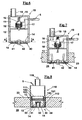
- FIG. 6 a diagrammatical view is provided of injecting device 10 of figures 2 and 3 , with a different passive valve 40.
- the blocking element consists of a resilient plate 41 connected to wall 13 in at least one point 42, in order to cover apertures 14.
- the plate 41 is adapted to bend under the action of the pressure of the gas, leaving apertures 14 free and allowing the flow of the gas towards the combustion chamber as indicated by the arrows.
- more plates can be provided, one for each opening 14.
- passive valve 30 or 40, chamber 12 and electrovalve 11 are integrated in a single element.
- wall 13 and chamber 12 are integrated in a hollow element 112, having a mouth 150 opposite to wall 13, in which an end 152 engages of electrovalve 111.
- electrovalve 111 is an injecting device for indirect injection of gas of a type available on the market.
- this electrovalve 111 is not directly exposed to the conditions of pressure and temperature present in combustion chamber 24 owing to the presence of the chamber and of the passive valve.
- the hollow element 112 houses head 23 like in the previous case, for example screwed or by a fixed joint. Its mouth 150 has a shoulder 151 against which the end 152 of electrovalve 111 abuts.
- the latter is not described in detail since of commercial type, and has an inner quick response solenoid and a stopper capable of releasing an amount of pressurized gas in quick time from feeding chamber 12.
- the gas entering chamber 12 opens automatically passive valve 30 and enters, with minimum delay, the combustion chamber.
- Valve 30, during the combustion is sealed owing to the mushroom shape of plate 31 and to the corresponding substantially conical shape of wall 13, without reducing the quick response capacity of the valve same.
- the gas is injected by an injecting device that combines a simple gas distributing part, i.e. the electrovalve, to a correspondingly easy part, i.e. the wall that can be crossed by the gas for the presence of the passive valve, and the chamber that is arranged between the wall and the electrovalve for shielding the latter from the combustion environment.
- an injecting device that combines a simple gas distributing part, i.e. the electrovalve, to a correspondingly easy part, i.e. the wall that can be crossed by the gas for the presence of the passive valve, and the chamber that is arranged between the wall and the electrovalve for shielding the latter from the combustion environment.
Landscapes
- Engineering & Computer Science (AREA)
- Chemical & Material Sciences (AREA)
- Combustion & Propulsion (AREA)
- Chemical Kinetics & Catalysis (AREA)
- General Chemical & Material Sciences (AREA)
- Oil, Petroleum & Natural Gas (AREA)
- Mechanical Engineering (AREA)
- General Engineering & Computer Science (AREA)
- Analytical Chemistry (AREA)
- Combustion Methods Of Internal-Combustion Engines (AREA)
- Exhaust Gas After Treatment (AREA)
- Output Control And Ontrol Of Special Type Engine (AREA)
- Portable Nailing Machines And Staplers (AREA)
Claims (8)
- Einspritzvorrichtung, die dafür vorgesehen ist, im Kopf eines Ottomotors angeordnet zu werden, dadurch gekennzeichnet, dass die Einspritzvorrichtung eine Wand (13) aufweist, die dem Brennraum zugewandt ist, und Folgendes umfasst:- einen Elektroventilabschnitt (11), welcher der Wand gegenüberliegend angeordnet ist,- ein passives Ventil (30), das an der Wand angeordnet ist, und- eine Kammer (12), die zwischen dem Elektroventilabschnitt und dem passiven Ventil angeordnet ist,wobei das Elektroventil mit druckbeaufschlagtem Gas beschickt wird und so ausgeführt ist, dass es mit Hilfe eines elektrischen Steuerungsmittels geöffnet werden kann, wobei beim Öffnen des Elektroventils das druckbeaufschlagte Gas in die Kammer einströmt und eine Bewegung der Wand und das anschließende Einströmen des Gases in den Brennraum aufgrund des automatischen Öffnens des passiven Ventils verursacht.
- Einspritzvorrichtung nach Anspruch 1, wobei das passive Ventil, die Kammer und das Elektroventil in einem einzigen Element integriert sind, das einen hohlen Bereich aufweist, der die Kammer definiert.
- Einspritzvorrichtung nach Anspruch 1, wobei das passive Ventil und die Kammer in einem hohlen Element integriert sind, das eine Mündung gegenüber der Wand aufweist, wobei ein Ende des Elektroventils in die Mündung eingreift.
- Einspritzvorrichtung nach Anspruch 3, wobei das Elektroventil eine Einspritzvorrichtung für die indirekte Einspritzung von Methan eines marktüblichen Typs ist.
- Einspritzvorrichtung nach Anspruch 1, wobei das passive Ventil mindestens eine in der Wand ausgebildete Öffnung und ein Blockierelement, das für das Abdecken der Öffnung in der Wand geeignet und auf der Seite des Brennraums angeordnet ist, umfasst, wobei das Blockierelement durch ein elastisches Mittel gegen die Wand gedrückt gehalten wird, um die Öffnung zu verschließen, und unter der Wirkung des Drucks von in die Kammer einströmendem Gas entgegen der Kraft des elastischen Mittels von der Wand gelöst wird, wodurch das Gas durch die Öffnung hindurch und in den Brennraum hinein strömen kann.
- Einspritzvorrichtung nach Anspruch 5, wobei das Blockierelement mindestens eine einzelne Platte ist, die einen Schaft aufweist, der sich durch die Wand hindurch erstreckt und in einen vergrößerten Abschnitt mündet, wobei die Platte durch eine Feder, die in der Kammer um den Schaft herum angeordnet und dem vergrößerten Abschnitt zugewandt ist, gegen die Wand gedrückt gehalten wird.
- Einspritzvorrichtung nach Anspruch 5, wobei das Blockierelement mindestens eine einzelne elastische Platte ist, die an mindestens einem Punkt mit der Wand verbunden ist, um die Öffnung abzudecken, wobei die Platte dafür geeignet ist, sich unter der Wirkung des Drucks des Gases durchzubiegen, wodurch die Öffnung frei gelassen wird.
- Gaseinspritzsystem für Ottomotoren mit einem Druckgasbehälter, einem Druckminderer und einer Einspritzvorrichtung zum Einspritzen von Gas direkt in den Brennraum des Motors, dadurch gekennzeichnet, dass die Einspritzvorrichtung Folgendes enthält:- einen Elektroventilabschnitt, welcher der Wand gegenüberliegend angeordnet ist,- ein passives Ventil, das an der Wand angeordnet ist, und- eine Kammer, die zwischen dem Elektroventilabschnitt und dem passiven Ventil angeordnet ist,wobei der Elektroventilabschnitt mit druckbeaufschlagtem Gas beschickt wird und so ausgeführt ist, dass er mit Hilfe eines elektrischen Steuerungsmittels geöffnet werden kann, so dass beim Öffnen des Elektroventils das druckbeaufschlagte Gas in die Kammer einströmt und das automatische Öffnen des passiven Ventils verursacht, wodurch das Gas in den Brennraum einströmen kann.
Applications Claiming Priority (1)
| Application Number | Priority Date | Filing Date | Title |
|---|---|---|---|
| IT000119A ITPI20050119A1 (it) | 2005-10-28 | 2005-10-28 | Sistema per l'iniezione di gas in motori a combustione interna ad accensione comandata |
Publications (3)
| Publication Number | Publication Date |
|---|---|
| EP1780396A2 EP1780396A2 (de) | 2007-05-02 |
| EP1780396A3 EP1780396A3 (de) | 2007-10-03 |
| EP1780396B1 true EP1780396B1 (de) | 2009-07-29 |
Family
ID=37758805
Family Applications (1)
| Application Number | Title | Priority Date | Filing Date |
|---|---|---|---|
| EP06021675A Not-in-force EP1780396B1 (de) | 2005-10-28 | 2006-10-16 | Gaseinspritzsystem für funkgezündeten Brennkraftmaschinen |
Country Status (4)
| Country | Link |
|---|---|
| EP (1) | EP1780396B1 (de) |
| AT (1) | ATE438032T1 (de) |
| DE (1) | DE602006008085D1 (de) |
| IT (1) | ITPI20050119A1 (de) |
Family Cites Families (3)
| Publication number | Priority date | Publication date | Assignee | Title |
|---|---|---|---|---|
| US5758865A (en) * | 1996-08-21 | 1998-06-02 | Kavlico Corporation | Fuel injection valve and engine including the same |
| US5752489A (en) * | 1997-02-10 | 1998-05-19 | Cummins Engine Company, Inc. | Integrated fuel measurement and control system for gaseous fuels |
| US6588406B2 (en) * | 2000-06-07 | 2003-07-08 | Radu Oprea | Dual fuel metering and supply system for internal combustion engines |
-
2005
- 2005-10-28 IT IT000119A patent/ITPI20050119A1/it unknown
-
2006
- 2006-10-16 EP EP06021675A patent/EP1780396B1/de not_active Not-in-force
- 2006-10-16 DE DE602006008085T patent/DE602006008085D1/de active Active
- 2006-10-16 AT AT06021675T patent/ATE438032T1/de not_active IP Right Cessation
Also Published As
| Publication number | Publication date |
|---|---|
| EP1780396A3 (de) | 2007-10-03 |
| EP1780396A2 (de) | 2007-05-02 |
| ATE438032T1 (de) | 2009-08-15 |
| ITPI20050119A1 (it) | 2007-04-29 |
| DE602006008085D1 (de) | 2009-09-10 |
Similar Documents
| Publication | Publication Date | Title |
|---|---|---|
| US5069189A (en) | Fuel injector system for internal combustion engine | |
| DE3681711D1 (de) | Kraftstoffeinspritzanlage fuer brennkraftmaschinen. | |
| US20130098325A1 (en) | Air supply device for 2 stroke engine | |
| CA2330609A1 (en) | Multi-fuel engine | |
| US7013847B2 (en) | Heading gas injection system (HGIS) direct injection system | |
| US4589386A (en) | Carburetor priming system for internal combustion engines | |
| WO2002073010A3 (de) | Abgaskrümmer | |
| TW358849B (en) | 2-stroke internal combustion engine | |
| PL1697627T3 (pl) | Elektrycznie zasilany wtryskiwacz do paliwa gazowego | |
| EP1780396A2 (de) | Gaseinspritzsystem für funkgezündeten Brennkraftmaschinen | |
| US5269280A (en) | Fuel injector for gaseous fuel | |
| JP2006188976A (ja) | 水素ガスエンジンと水素ガスエンジンに使用するインジェクター | |
| EP1856387B1 (de) | Kraftstoffeinspritzsystem für zweitaktverbrennungsmotoren | |
| RU2039644C1 (ru) | Самозапускаемый портативный инструмент | |
| JPS63207569A (ja) | 内燃式ピストン駆動装置 | |
| DE69208475D1 (de) | Kraftstoffeinspritzvorrichtung | |
| US4046115A (en) | Free piston engine fuel feeding apparatus | |
| CA1094412A (en) | Compressed air-actuated fluid injection apparatus | |
| US5700402A (en) | Crankcase fuel injection system for two-cycle internal combustion engines | |
| US20030041818A1 (en) | Internal combustion engine fuel check valve | |
| CN214063164U (zh) | 燃气喷嘴 | |
| US878933A (en) | Fuel-feeding mechanism for internal-combustion engines. | |
| ATE300671T1 (de) | Gaseinspritzventil | |
| JP2006177200A (ja) | 水素ガスエンジンと水素ガスエンジンに使用するインジェクター | |
| CN118855615A (zh) | 一种船舶双燃料发动机燃料喷射装置 |
Legal Events
| Date | Code | Title | Description |
|---|---|---|---|
| PUAI | Public reference made under article 153(3) epc to a published international application that has entered the european phase |
Free format text: ORIGINAL CODE: 0009012 |
|
| AK | Designated contracting states |
Kind code of ref document: A2 Designated state(s): AT BE BG CH CY CZ DE DK EE ES FI FR GB GR HU IE IS IT LI LT LU LV MC NL PL PT RO SE SI SK TR |
|
| AX | Request for extension of the european patent |
Extension state: AL BA HR MK YU |
|
| PUAL | Search report despatched |
Free format text: ORIGINAL CODE: 0009013 |
|
| AK | Designated contracting states |
Kind code of ref document: A3 Designated state(s): AT BE BG CH CY CZ DE DK EE ES FI FR GB GR HU IE IS IT LI LT LU LV MC NL PL PT RO SE SI SK TR |
|
| AX | Request for extension of the european patent |
Extension state: AL BA HR MK YU |
|
| 17P | Request for examination filed |
Effective date: 20080331 |
|
| AKX | Designation fees paid |
Designated state(s): AT BE BG CH CY CZ DE DK EE ES FI FR GB GR HU IE IS IT LI LT LU LV MC NL PL PT RO SE SI SK TR |
|
| GRAP | Despatch of communication of intention to grant a patent |
Free format text: ORIGINAL CODE: EPIDOSNIGR1 |
|
| GRAS | Grant fee paid |
Free format text: ORIGINAL CODE: EPIDOSNIGR3 |
|
| GRAA | (expected) grant |
Free format text: ORIGINAL CODE: 0009210 |
|
| AK | Designated contracting states |
Kind code of ref document: B1 Designated state(s): AT BE BG CH CY CZ DE DK EE ES FI FR GB GR HU IE IS IT LI LT LU LV MC NL PL PT RO SE SI SK TR |
|
| REG | Reference to a national code |
Ref country code: GB Ref legal event code: FG4D |
|
| REG | Reference to a national code |
Ref country code: CH Ref legal event code: EP |
|
| REG | Reference to a national code |
Ref country code: IE Ref legal event code: FG4D |
|
| REF | Corresponds to: |
Ref document number: 602006008085 Country of ref document: DE Date of ref document: 20090910 Kind code of ref document: P |
|
| NLV1 | Nl: lapsed or annulled due to failure to fulfill the requirements of art. 29p and 29m of the patents act | ||
| PG25 | Lapsed in a contracting state [announced via postgrant information from national office to epo] |
Ref country code: LT Free format text: LAPSE BECAUSE OF FAILURE TO SUBMIT A TRANSLATION OF THE DESCRIPTION OR TO PAY THE FEE WITHIN THE PRESCRIBED TIME-LIMIT Effective date: 20090729 Ref country code: IS Free format text: LAPSE BECAUSE OF FAILURE TO SUBMIT A TRANSLATION OF THE DESCRIPTION OR TO PAY THE FEE WITHIN THE PRESCRIBED TIME-LIMIT Effective date: 20091129 Ref country code: ES Free format text: LAPSE BECAUSE OF FAILURE TO SUBMIT A TRANSLATION OF THE DESCRIPTION OR TO PAY THE FEE WITHIN THE PRESCRIBED TIME-LIMIT Effective date: 20091109 Ref country code: SE Free format text: LAPSE BECAUSE OF FAILURE TO SUBMIT A TRANSLATION OF THE DESCRIPTION OR TO PAY THE FEE WITHIN THE PRESCRIBED TIME-LIMIT Effective date: 20090729 Ref country code: FI Free format text: LAPSE BECAUSE OF FAILURE TO SUBMIT A TRANSLATION OF THE DESCRIPTION OR TO PAY THE FEE WITHIN THE PRESCRIBED TIME-LIMIT Effective date: 20090729 Ref country code: AT Free format text: LAPSE BECAUSE OF FAILURE TO SUBMIT A TRANSLATION OF THE DESCRIPTION OR TO PAY THE FEE WITHIN THE PRESCRIBED TIME-LIMIT Effective date: 20090729 |
|
| PG25 | Lapsed in a contracting state [announced via postgrant information from national office to epo] |
Ref country code: SI Free format text: LAPSE BECAUSE OF FAILURE TO SUBMIT A TRANSLATION OF THE DESCRIPTION OR TO PAY THE FEE WITHIN THE PRESCRIBED TIME-LIMIT Effective date: 20090729 Ref country code: PL Free format text: LAPSE BECAUSE OF FAILURE TO SUBMIT A TRANSLATION OF THE DESCRIPTION OR TO PAY THE FEE WITHIN THE PRESCRIBED TIME-LIMIT Effective date: 20090729 Ref country code: NL Free format text: LAPSE BECAUSE OF FAILURE TO SUBMIT A TRANSLATION OF THE DESCRIPTION OR TO PAY THE FEE WITHIN THE PRESCRIBED TIME-LIMIT Effective date: 20090729 Ref country code: LV Free format text: LAPSE BECAUSE OF FAILURE TO SUBMIT A TRANSLATION OF THE DESCRIPTION OR TO PAY THE FEE WITHIN THE PRESCRIBED TIME-LIMIT Effective date: 20090729 |
|
| PG25 | Lapsed in a contracting state [announced via postgrant information from national office to epo] |
Ref country code: PT Free format text: LAPSE BECAUSE OF FAILURE TO SUBMIT A TRANSLATION OF THE DESCRIPTION OR TO PAY THE FEE WITHIN THE PRESCRIBED TIME-LIMIT Effective date: 20091129 Ref country code: BG Free format text: LAPSE BECAUSE OF FAILURE TO SUBMIT A TRANSLATION OF THE DESCRIPTION OR TO PAY THE FEE WITHIN THE PRESCRIBED TIME-LIMIT Effective date: 20091029 |
|
| PG25 | Lapsed in a contracting state [announced via postgrant information from national office to epo] |
Ref country code: RO Free format text: LAPSE BECAUSE OF FAILURE TO SUBMIT A TRANSLATION OF THE DESCRIPTION OR TO PAY THE FEE WITHIN THE PRESCRIBED TIME-LIMIT Effective date: 20090729 Ref country code: DK Free format text: LAPSE BECAUSE OF FAILURE TO SUBMIT A TRANSLATION OF THE DESCRIPTION OR TO PAY THE FEE WITHIN THE PRESCRIBED TIME-LIMIT Effective date: 20090729 Ref country code: CZ Free format text: LAPSE BECAUSE OF FAILURE TO SUBMIT A TRANSLATION OF THE DESCRIPTION OR TO PAY THE FEE WITHIN THE PRESCRIBED TIME-LIMIT Effective date: 20090729 Ref country code: EE Free format text: LAPSE BECAUSE OF FAILURE TO SUBMIT A TRANSLATION OF THE DESCRIPTION OR TO PAY THE FEE WITHIN THE PRESCRIBED TIME-LIMIT Effective date: 20090729 |
|
| PG25 | Lapsed in a contracting state [announced via postgrant information from national office to epo] |
Ref country code: SK Free format text: LAPSE BECAUSE OF FAILURE TO SUBMIT A TRANSLATION OF THE DESCRIPTION OR TO PAY THE FEE WITHIN THE PRESCRIBED TIME-LIMIT Effective date: 20090729 Ref country code: MC Free format text: LAPSE BECAUSE OF NON-PAYMENT OF DUE FEES Effective date: 20091031 Ref country code: BE Free format text: LAPSE BECAUSE OF FAILURE TO SUBMIT A TRANSLATION OF THE DESCRIPTION OR TO PAY THE FEE WITHIN THE PRESCRIBED TIME-LIMIT Effective date: 20090729 |
|
| PLBE | No opposition filed within time limit |
Free format text: ORIGINAL CODE: 0009261 |
|
| STAA | Information on the status of an ep patent application or granted ep patent |
Free format text: STATUS: NO OPPOSITION FILED WITHIN TIME LIMIT |
|
| 26N | No opposition filed |
Effective date: 20100503 |
|
| PG25 | Lapsed in a contracting state [announced via postgrant information from national office to epo] |
Ref country code: IE Free format text: LAPSE BECAUSE OF NON-PAYMENT OF DUE FEES Effective date: 20091016 Ref country code: GR Free format text: LAPSE BECAUSE OF FAILURE TO SUBMIT A TRANSLATION OF THE DESCRIPTION OR TO PAY THE FEE WITHIN THE PRESCRIBED TIME-LIMIT Effective date: 20091030 |
|
| PGFP | Annual fee paid to national office [announced via postgrant information from national office to epo] |
Ref country code: DE Payment date: 20101021 Year of fee payment: 5 |
|
| PGFP | Annual fee paid to national office [announced via postgrant information from national office to epo] |
Ref country code: IT Payment date: 20101030 Year of fee payment: 5 |
|
| PG25 | Lapsed in a contracting state [announced via postgrant information from national office to epo] |
Ref country code: LU Free format text: LAPSE BECAUSE OF NON-PAYMENT OF DUE FEES Effective date: 20091016 |
|
| REG | Reference to a national code |
Ref country code: CH Ref legal event code: PL |
|
| GBPC | Gb: european patent ceased through non-payment of renewal fee |
Effective date: 20101016 |
|
| PG25 | Lapsed in a contracting state [announced via postgrant information from national office to epo] |
Ref country code: HU Free format text: LAPSE BECAUSE OF FAILURE TO SUBMIT A TRANSLATION OF THE DESCRIPTION OR TO PAY THE FEE WITHIN THE PRESCRIBED TIME-LIMIT Effective date: 20100130 |
|
| PG25 | Lapsed in a contracting state [announced via postgrant information from national office to epo] |
Ref country code: CH Free format text: LAPSE BECAUSE OF NON-PAYMENT OF DUE FEES Effective date: 20101031 Ref country code: LI Free format text: LAPSE BECAUSE OF NON-PAYMENT OF DUE FEES Effective date: 20101031 |
|
| PG25 | Lapsed in a contracting state [announced via postgrant information from national office to epo] |
Ref country code: GB Free format text: LAPSE BECAUSE OF NON-PAYMENT OF DUE FEES Effective date: 20101016 Ref country code: TR Free format text: LAPSE BECAUSE OF FAILURE TO SUBMIT A TRANSLATION OF THE DESCRIPTION OR TO PAY THE FEE WITHIN THE PRESCRIBED TIME-LIMIT Effective date: 20090729 |
|
| PG25 | Lapsed in a contracting state [announced via postgrant information from national office to epo] |
Ref country code: CY Free format text: LAPSE BECAUSE OF FAILURE TO SUBMIT A TRANSLATION OF THE DESCRIPTION OR TO PAY THE FEE WITHIN THE PRESCRIBED TIME-LIMIT Effective date: 20090729 |
|
| PGFP | Annual fee paid to national office [announced via postgrant information from national office to epo] |
Ref country code: FR Payment date: 20111104 Year of fee payment: 6 |
|
| REG | Reference to a national code |
Ref country code: FR Ref legal event code: ST Effective date: 20130628 |
|
| PG25 | Lapsed in a contracting state [announced via postgrant information from national office to epo] |
Ref country code: DE Free format text: LAPSE BECAUSE OF NON-PAYMENT OF DUE FEES Effective date: 20130501 |
|
| REG | Reference to a national code |
Ref country code: DE Ref legal event code: R119 Ref document number: 602006008085 Country of ref document: DE Effective date: 20130501 |
|
| PG25 | Lapsed in a contracting state [announced via postgrant information from national office to epo] |
Ref country code: IT Free format text: LAPSE BECAUSE OF NON-PAYMENT OF DUE FEES Effective date: 20121016 Ref country code: FR Free format text: LAPSE BECAUSE OF NON-PAYMENT OF DUE FEES Effective date: 20121031 |