EP1780109A2 - Control system and motorcycle with the same - Google Patents
Control system and motorcycle with the same Download PDFInfo
- Publication number
- EP1780109A2 EP1780109A2 EP06022863A EP06022863A EP1780109A2 EP 1780109 A2 EP1780109 A2 EP 1780109A2 EP 06022863 A EP06022863 A EP 06022863A EP 06022863 A EP06022863 A EP 06022863A EP 1780109 A2 EP1780109 A2 EP 1780109A2
- Authority
- EP
- European Patent Office
- Prior art keywords
- rear wheel
- motorcycle
- roll rate
- control system
- holding member
- Prior art date
- Legal status (The legal status is an assumption and is not a legal conclusion. Google has not performed a legal analysis and makes no representation as to the accuracy of the status listed.)
- Granted
Links
Images






Classifications
-
- B—PERFORMING OPERATIONS; TRANSPORTING
- B62—LAND VEHICLES FOR TRAVELLING OTHERWISE THAN ON RAILS
- B62K—CYCLES; CYCLE FRAMES; CYCLE STEERING DEVICES; RIDER-OPERATED TERMINAL CONTROLS SPECIALLY ADAPTED FOR CYCLES; CYCLE AXLE SUSPENSIONS; CYCLE SIDECARS, FORECARS, OR THE LIKE
- B62K21/00—Steering devices
- B62K21/005—Steering pivot axis arranged within the wheel, e.g. for a hub center steering arrangement
-
- B—PERFORMING OPERATIONS; TRANSPORTING
- B62—LAND VEHICLES FOR TRAVELLING OTHERWISE THAN ON RAILS
- B62J—CYCLE SADDLES OR SEATS; AUXILIARY DEVICES OR ACCESSORIES SPECIALLY ADAPTED TO CYCLES AND NOT OTHERWISE PROVIDED FOR, e.g. ARTICLE CARRIERS OR CYCLE PROTECTORS
- B62J45/00—Electrical equipment arrangements specially adapted for use as accessories on cycles, not otherwise provided for
- B62J45/40—Sensor arrangements; Mounting thereof
- B62J45/41—Sensor arrangements; Mounting thereof characterised by the type of sensor
- B62J45/415—Inclination sensors
- B62J45/4151—Inclination sensors for sensing lateral inclination of the cycle
-
- B—PERFORMING OPERATIONS; TRANSPORTING
- B62—LAND VEHICLES FOR TRAVELLING OTHERWISE THAN ON RAILS
- B62K—CYCLES; CYCLE FRAMES; CYCLE STEERING DEVICES; RIDER-OPERATED TERMINAL CONTROLS SPECIALLY ADAPTED FOR CYCLES; CYCLE AXLE SUSPENSIONS; CYCLE SIDECARS, FORECARS, OR THE LIKE
- B62K25/00—Axle suspensions
- B62K25/005—Axle suspensions characterised by the axle being supported at one end only
Definitions
- the present invention relates to a control system of a motorcycle and a motorcycle including such a control system.
- front-and-rear-wheel steering systems have been developed that steer the rear wheel according to the steering of the front wheel of a motorcycle.
- Some conventional front-and-rear-wheel steering systems have a mechanism that steers the rear wheel mechanically or electrically according to the steering angle of the front wheel (for example, see JP 61-160374 A , JP 2927477 B , and JP 3206610 B ), and other systems have a mechanism that steer the rear wheel automatically according to a lateral force exerted on the rear wheel (for example, see JP 2829009 B and JP 7-98507 B ).
- JP 61-160374 A , JP 2927477 B , JP 3206610 B , JP 2829009 B , and JP 7-98507 B when any one of the mechanisms disclosed in JP 61-160374 A , JP 2927477 B , JP 3206610 B , JP 2829009 B , and JP 7-98507 B is used, the stability of the motorcycle at the time of straight running is improved while the stability of the motorcycle at the time of turning is decreased.
- the steering amount of the rear wheel is changed between the high speed running and the low and middle speed running. This is intended to give the desired stability during straight running and stability during steering at high speed running and during the low and middle speed running, respectively.
- a speed, a yaw rate, a roll rate and the like are detected and the rear wheel is steered in phase with the steering direction of the front wheel based on the detection results.
- the vibration of the motorcycle during steering the rear wheel is damped.
- the steering angle of the rear wheel is determined based on that of the front wheel.
- a large steering torque and a large roll angle are needed to turn the motorcycle in an unstable condition. For this reason, the drivability of the motorcycle decreases and stable turning cannot be performed in some cases.
- preferred embodiments of the present invention provide a control system of amotorcycle that is capable of improving running stability and preventing turning performance from being degraded, and a motorcycle including such a novel control system.
- the rear wheel supporting mechanism rotatably and swingably holds the rear wheel.
- the controller causes the swinging device to swing the rear wheel based on the roll rate of the motorcycle detected by the roll rate detector.
- the rear wheel is swung based on the roll rate of the motorcycle, thereby making it possible to adjust the ratio of a lateral force of the front wheel to a lateral force of the rear wheel so as to reduce the roll rate of the motorcycle. This improves the running stability of the motorcycle and prevents the turning performance from being degraded.
- the rear wheel supporting mechanism may support the rear wheel tiltably with respect to an axis that is substantially parallel to the up-and-down direction of the holding member, and the controller may tilt the rear wheel with respect to the axis that is substantially parallel to the up-and-down direction of the holding member based on the roll rate detected by the roll rate detector.
- the controller tilts the rear wheel with respect to the axis parallel to the up-and-down direction of the holding member based on the roll rate of the motorcycle detected by the roll rate detector.
- the ratio of the lateral force of the front wheel to the lateral force of the rear wheel can be adjusted so that the roll rate of the motorcycle can be reduced.
- the running stability of the motorcycle can be improved and the turning performance can be prevented from being degraded.
- the rear wheel supporting mechanism may support the rear wheel tiltably with respect to an axis that is substantially parallel to the back-and-forth direction of the holding member, and the controller may tilt the rear wheel with respect to the axis that is substantially parallel to the back-and-forth direction of the holding member based on the roll rate detected by the roll rate detector.
- the controller tilts the rear wheel with respect to the axis parallel to the back-and-forth direction of the holding member based on the roll rate of the motorcycle detected by the roll rate detector.
- the ratio of the lateral force of the front wheel to the lateral force of the rear wheel can be adjusted so that the roll rate of the motorcycle can be reduced.
- the running stability of the motorcycle can be improved and the turning performance can be prevented from being degraded.
- the control system may further include a speed detector that detects the vehicle speed of the motorcycle, the controller may determine a lean angle of the rear wheel based on the product of the roll rate detected by the roll rate detector and a factor, and the factor may be determined based on the vehicle speed detected by the speed detector.
- the lean angle of the rear wheel can be determined depending on the roll rate and the vehicle speed of the motorcycle.
- the roll rate of the motorcycle can be reliably reduced.
- the running stability of the motorcycle can be reliably improved and the turning performance can be reliably prevented from being degraded.
- the controller may tilt the rear wheel at a response speed determined based on the vehicle speed detected by the speed detector.
- the controller may tilt the rear wheel with a first-order delay filter and a time constant of the first-order delay filter may be determined based on the vehicle speed detected by the speed detector.
- the instability phenomenon unique to the motorcycle can be more reliably prevented.
- the running stability of the motorcycle can be more reliably improved and the turning performance can be more reliably prevented from being degraded.
- a motorcycle includes a control system arranged to control the balance of a motorcycle, a driving device arranged to generate a driving force to rotate a rear wheel of the motorcycle and a driving force transmission mechanism arranged to transmit the driving force generated by the driving device to the rear wheel
- the control system includes a holding member arranged to rotatably and steerably hold a front wheel, a rear wheel supporting mechanism connected to the holding member and arranged to rotatably and swingably support the rear wheel, a roll rate detector arranged to detect a roll rate of the motorcycle, a swinging device arranged to swing the rear wheel, and a controller arranged to cause the swinging device to swing the rear wheel based on the roll rate detected by the roll rate detector.
- the driving force generated by the driving device is transmitted to the rear wheel by the driving force transmission mechanism and the rear wheel is driven.
- the balance of the motorcycle is controlled by the control system.
- the roll rate of the motorcycle can be reduced.
- the running stability of the motorcycle can be improved and the turning performance can be prevented from being degraded.
- the first holding member holding the front wheel and the second holding member holding the rear wheel are swingably attached to each other.
- the controller swings one of the first and second holding members with respect to the other based on the roll rate of the motorcycle detected by the roll rate detector.
- one of the first and second holding members is swung with respect to the other based on the roll rate of the motorcycle, thereby making it possible to adjust the ratio of a lateral force of the front wheel to a lateral force of the rear wheel so as to reduce the roll rate of the motorcycle.
- the running stability of the motorcycle can be improved and the turning performance can be prevented from being degraded.
- the first and second holding members may be attached to each other rotatably about an axis that extends in the back-and-forth direction, an extension line of the axis that extends in the back-and-forth direction may pass substantially through a contact point between the rear wheel and the ground, and the controller may relatively rotate one of the first and second holding members with respect to the other based on the roll rate detected by the roll rate detector.
- the controller relatively rotates one of the first and second holding members with respect to the other about the axis that extends in the back-and-forth direction based on the roll rate of the motorcycle detected by the roll rate detector.
- the ratio of the lateral force of the front wheel to the lateral force of the rear wheel can be adjusted so that the roll rate of the motorcycle can be reduced.
- the running stability of the motorcycle can be improved and the turning performance can be prevented from being degraded.
- first and second holding members are attached to each other so that the extension line of the axis that extends in the above-mentioned back-and-forth direction passes substantially through the contact point between the rear wheel and the ground. For this reason, when the second holding member is rotated with respect to the first holding member, the rear wheel rotates about the vicinity of the contact point with the ground. Thus, the rear wheel can be prevented from slipping on the ground and safety can be improved.
- the control system may further include a speed detector that detects a vehicle speed of the motorcycle and the controller may determine a relative rotation angle of the second holding member with respect to the first holding member based on the product of the roll rate detected by the roll rate detector and a factor, the factor being determined based on the vehicle speed detected by the speed detector.
- the relative rotation angle of the second holding member with respect to the first holding member may be determined depending on the roll rate and the vehicle speed of the motorcycle.
- the roll rate of the motorcycle can be reliably reduced.
- the running stability of the motorcycle can be reliably improved and the turning performance can be reliably prevented from being degraded.
- the controller may relatively rotate one of the first and second holding members with respect to the other at a response speed determined based on the vehicle speed detected by the speed detector.
- the instability phenomenon unique to the motorcycle can be reliably prevented.
- the running stability of the motorcycle can be reliably improved and the turning performance can be reliably prevented from being degraded.
- the controller may relatively rotate one of the first and second holding members with respect to the other with a first-order delay filter and a time constant of the first-order delay filter may be determined based on the vehicle speed detected by the speed detector.
- the instability phenomenon unique to the motorcycle can be more reliably prevented.
- the running stability of the motorcycle can be more reliably improved and the turning performance can be more reliably prevented from being degraded.
- a motorcycle includes a control system arranged to control the balance of a motorcycle, a driving device arranged to generate a driving force to rotate a rear wheel of the motorcycle and a driving force transmission mechanism arranged to transmit the driving force generated by the driving device to the rear wheel, and the control system includes a first holding member arranged to rotatably and steerably hold a front wheel of the motorcycle, a second holding member that is attached to the first holding member arranged to swingably hold a rear wheel, a roll rate detector arranged to detect a roll rate of the motorcycle, a swinging device arranged to swing one of the first and second holding members with respect to the other, and a controller arranged to cause the swinging device to swing one of the first and second holding members with respect to the other based on the roll rate detected by the roll rate detector.
- the driving force generated by the driving device is transmitted to the rear wheel by the driving force transmission mechanism and the rear wheel is driven.
- the balance of the motorcycle is controlled by the control system.
- the roll rate of the motorcycle can be reduced.
- the running stability of the motorcycle can be improved and the turning performance can be prevented from being degraded.
- Fig. 1 is an external side view of a motorcycle according to a first preferred embodiment of the present invention.
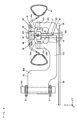
- Fig. 2 is a sectional view taken along the arrowed line A-A in the motorcycle in Fig. 1.
- Fig. 3 is a sectional view taken along the arrowed line B-B in the motorcycle in Fig. 1.
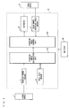
- Fig. 4 is a block diagram showing one example of a control system of the motorcycle according to the first preferred embodiment of the present invention.
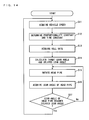
- Fig. 5 is a flowchart showing one example of a control method by the control system of the motorcycle according to the first preferred embodiment of the present invention.
- Fig. 6 is a diagram showing one example of a proportionality constant.
- Fig. 7 is a diagram showing one example of a time constant.
- Fig. 8 is a sectional view taken along the arrowed line B-B in Fig. 1 according to a second preferred embodiment of the present invention.
- Fig. 9 is an external side view of a motorcycle according to a third preferred embodiment of the present invention.
- Fig. 10 is a schematic side sectional view of a coupling portion of a head pipe and a main body frame.
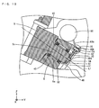
- Fig. 11 is a schematic top view of the coupling portion of the head pipe and the main body frame.
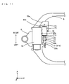
- Fig. 12 is a schematic rear view of the coupling portion of the head pipe and the main body frame.
- Fig. 13 is a block diagram showing one example of a control system of the motorcycle according to the third preferred embodiment of the present invention.
- Fig. 14 is a flowchart showing one example of a control method by the control system of the motorcycle according to the third preferred embodiment of the present invention.
- Fig. 1 is an external side view of a motorcycle according to a first preferred embodiment of the present invention.
- a front wheel 1 is rotatably held by a front fork 2.
- the front fork 2 is attached to a head pipe 5 so as to be turnable to the right and left.
- a handle 3 is attached to the upper end of the front fork 2.
- a rider operates the handle 3, so that the front fork 2 turns to the right and left of the motorcycle 100.
- the front wheel 1 is steered.
- a main body frame 6 is connected to the rear side of the head pipe 5.
- An engine 7 is held in the center of the main body frame 6.
- a fuel tank 8 is provided above the engine 7, and a front seat 9a and a rear seat 9b are provided behind the fuel tank 8.
- a rear arm 52 (see Figs. 2 and 3) is connected to the main body frame 6 so as to extend behind the engine 7.
- the rear arm 52 rotatably holds a rear wheel 4 and a chain sprocket 54.
- a vehicle speed sensor 11 is provided in the vicinity of the lower end of the front fork 2.
- a roll rate sensor 14 is provided under the rear seat 9b.
- a rear wheel steering angle sensor 17 is provided in the rear arm 52 on the side of the rear wheel 4.
- a steering angle calculation unit 15a and a steering angle control unit 15b are provided below the front seat 9a, and an actuator 16 is provided on the rear arm 52 near the rear wheel 4.
- the vehicle speed sensor 11, the roll rate sensor 14, the steering angle calculation unit 15a, the steering angle control unit 15b, the actuator 16, and the rear wheel steering angle sensor 17 will be described in detail below.
- Fig. 2 is a sectional view taken along the arrowed line A-A in the motorcycle 100 in Fig. 1
- Fig. 3 is a sectional view taken along the arrowed line B-B in the motorcycle 100 in Fig. 1.
- the side-to-side direction of the motorcycle 100 is defined as the X direction and the back-and-forth direction of the motorcycle 100 is defined as the Y direction
- the vertical direction of the motorcycle 100 is defined as the Z direction.
- one end of the rear arm 52 that extends in the Y direction is connected to the main body frame 6 with a rotary connection shaft 53c. This enables the rear arm 52 to swing up and down.
- the rear arm 52 has a wide portion 52d formed in the X direction near a portion connected to the main body frame 6.
- a narrow portion 52c narrower than the wide portion 52d is arranged so as to extend in the Y direction from one side of the wide portion 52d in the X direction.
- Supporters 52a, 52b extend substantially parallel to each other in the X direction from the center of the narrow portion 52c and the end thereof.
- a drive shaft holding hole 52h that extends in the X direction is formed in the narrow portion 52c between the supporters 52a and 52b.
- a drive shaft 51 is inserted into the drive shaft holding hole 52h.
- the drive shaft 51 is rotatably held by the rear arm 52.
- One end of the drive shaft 51 is coupled to a constant velocity universal joint 51j.
- the constant velocity universal joint 51j is shown in a simplified manner in Figs. 2 and 3, the constant velocity universal joint 51j is composed of an inner race that holds one end of the drive shaft 51, an outer race that arranged so as to cover the inner race, a plurality of balls attached between the inner race and the outer race, a boot and the like.
- the constant velocity universal joint 51j is positioned between the supporters 52a and 52b and connected to the rear wheel rotary shaft 43, described below.
- the chain sprocket 54 is connected to the other end of the drive shaft 51.
- a chain 55 is put on the chain sprocket 54.
- Coupling members 45a and 45b in an axle shaft supporting member 45 are attached in the vicinity of each of the edges of the supporters 52a, 52b with the rotary connection shafts 53a, 53b, respectively. This enables the axle shaft supporting member 45 to swing with respect to the supporters 52a, 52b of the rear arm 52 about the rotary connection shafts 53a, 53b as indicated by the arrow P in Fig. 3.
- the coupling portions 45a, 45b of the axle shaft supporting member 45 are formed in an L-shape in the X-Y plane, respectively, and provided so as to be opposite to each other.
- a cylindrical portion 45c that extends in the X direction from the coupling portions 45a, 45b is formed in the axle shaft supporting member 45.
- the rear wheel rotary shaft 43 is rotatably held inside the cylindrical portion 45c with a bearing 44 provided therebetween.
- One end of the rear wheel rotary shaft 43 is connected to the constant velocity universal joint 51j.
- the other end of the rear wheel rotary shaft 43 is connected to a rear wheel hub 42.
- the one end of the rear wheel rotary shaft 43 may be integral with the outer race of the constant velocity universal joint 51j.
- the rear wheel hub 42 is substantially circular (not shown) in the Z-Y plane.
- the rear wheel 4 is connected to the rear wheel hub 42.
- a tire 41 is mounted on the periphery of the rear wheel 4.
- the driving force of the engine 7 in Fig. 1 is transmitted through the chain 55 to the chain sprocket 54, and causes the chain sprocket 54 to rotate.
- the drive shaft 51 rotates with the chain sprocket 54 as indicated by the arrow K in Fig. 2.
- the rear wheel rotary shaft 43 is rotated, so that the rear wheel hub 42 and the rear wheel 4 are rotated.
- the drive shaft 51 and the rear wheel rotary shaft 43 are connected to each other by the constant velocity universal joint 51j, thereby transmitting the turning force of the drive shaft 51 to the rear wheel rotary shaft 43 even if the axial center of the drive shaft 51 is misaligned with that of the rear wheel rotary shaft 43.
- the actuator 16 is provided on the narrow portion 52c of the rear arm 52.
- a knuckle arm 46 is preferably integral with and formed above the cylindrical portion 45c of the axle shaft supporting member 45, which extends so as to tilt with respect to the Z direction.
- the actuator 16 includes, for example, a servo motor.
- a rotary shaft 161 of the servo motor sticks out so as to extend from substantially the center of the actuator 16 in the Y direction.
- One end of a swing arm 162 is coupled to the rotary shaft 161.
- One end of a tie-rod 164 is swingably coupled to the other end of the swing arm 162.
- the other end of the tie-rod 164 is swingably coupled to the upper end of the knuckle arm 46.
- the actuator 16 operates to rotate the rotary shaft 161. This causes the other end of the swing arm 162 to swing about the rotary shaft 161 in the directions indicated by the arrow Q. Thus, the upper end of the knuckle arm 46 is moved in the X direction by the tie-rod 164. As a result, as mentioned above, the axle shaft supporting member 45 swings about the rotary connection shafts 53a, 53b as indicated by the arrow P.
- the operation of the actuator 16 makes the rear wheel 4 tilt with respect to the Z direction in the X-Z plane.
- the lean angle of the rear wheel 4 with respect to the Z direction is referred to as a rear wheel steering angle ⁇ 1.
- the actuator 16 is controlled by the steering angle control unit 15b.
- the inventors discovered through a variety of experiments and the like that reducing the roll rate of the motorcycle can prevent the instability phenomenon unique to the motorcycle including sway during low speed running, unpleasant vibrations during the high speed running, behavior of the motorcycle caused by external influences such as wind and irregularity of the ground, and the like.
- the inventors focused attention on the fact that the frequency of the above-mentioned instability phenomenon and a damping factor thereof are determined depending on the speed of the motorcycle.
- the proportionality constant is determined according to the speed of the motorcycle 100, and then the target steering angle of the rear wheel 4 is determined by multiplying the roll rate of the motorcycle 100 by the proportionality constant.
- the ratio of the lateral force of the front wheel 1 to that of the rear wheel 4 is adjusted by steering the rear wheel 4 so that the rear wheel 4 is tilted at this target steering angle.
- the roll rate of the motorcycle 100 is reduced.
- the proportionality constant is determined so that the ratio of the lateral force of the front wheel 1 to that of the rear wheel 4 is the most appropriate value to reduce the roll rate of the motorcycle 100.
- the response speed is determined based on the speed of the motorcycle 100 and the rear wheel 4 is steered when the motorcycle 100 reaches the response speed so that the rear wheel 4 is tilted at the target steering angle. This makes it possible to more reliably prevent the above-mentioned instability phenomenon. Details will be described below.
- Fig. 4 is a block diagram showing one example of a control system 10 of the motorcycle 100 according to this preferred embodiment.
- the control system 10 of the motorcycle 100 includes the vehicle speed sensor 11, the roll rate sensor 14, the steering angle calculation unit 15a, the steering angle control unit 15b, the actuator 16, and the rear wheel steering angle sensor 17.
- the vehicle speed sensor 11 detects the speed of the motorcycle 100 based on the number of revolutions of the front wheel 1.
- the roll rate sensor 14 detects the roll rate of the motorcycle 100, that is, the angular velocity of the motorcycle 100 around the axis that extends in the back-and-forth direction.
- the rear wheel steering angle sensor 17 detects the rear wheel steering angle ⁇ 1.
- the steering angle calculation unit 15a and the steering angle control unit 15b preferably include, for example, a CPU (Central Processing Unit) and a storage device or a microcomputer.
- the detected values of the vehicle speed sensor 11 and the roll rate sensor 14 are input to the steering angle calculation unit 15a.
- the steering angle calculation unit 15a calculates the target steering angle of the rear wheel 4 based on the input detected values.
- the steering angle control unit 15b controls the operation of the actuator 16 based on the target steering angle calculated by the steering angle calculation unit 15a.
- the steering angle control unit 15b controls the operation of the actuator 16 to adjust the rear wheel steering angle ⁇ 1 of the rear wheel 4.
- the adjusted rear wheel steering angle ⁇ 1 is detected by the rear wheel steering angle sensor 17 and the detected rear wheel steering angle ⁇ 1 is input to the steering angle control unit 15b. In this way, feedback control is performed on the actuator 16 based on the rear wheel steering angle ⁇ 1.
- Fig. 5 is a flowchart showing one example of a control method by the control system 10 of the motorcycle 100 according to this preferred embodiment.
- the steering angle calculation unit 15a of the control system 10 initially acquires the speed of the motorcycle 100 from the vehicle speed sensor 11 (step S1). Next, the steering angle calculation unit 15a determines the proportionality constant and time constant based on the speed of the motorcycle 100 acquired in step S1 (step S2). The proportionality constant and time constant change depending on the vehicle speed. The relationships between the proportionality constant and the vehicle speed are stored in the steering angle calculation unit 15a.
- the steering angle calculation unit 15a subsequently acquires the roll rate ⁇ from the roll rate sensor 14 (step S3) . Then, the steering angle calculation unit 15a calculates the target steering angle ⁇ 1 and the delayed steering angle ⁇ 2 by the formulas (1) and (2) mentioned below (step S4).
- K is the proportionality constant determined in step S2.
- T is the time constant determined in step S2 and s is a Laplacean.
- the steering angle control unit 15b acquires the rear wheel steering angle ⁇ 1 from the rear wheel steering angle sensor 17 (step S6).
- the steering angle control unit 15b subsequently determines whether or not the rear wheel steering angle ⁇ 1 acquired in step S6 reaches the delayed steering angle ⁇ 2 (step S7).
- the steering angle calculation unit 15a returns to step S1.
- step S7 When the rear wheel steering angle ⁇ 1 does not reach the delayed steering angle ⁇ 2 in step S7, the steering angle control unit 15b repeats step S5 to step S7 until the rear wheel steering angle ⁇ 1 reaches the delayed steering angle ⁇ 2.
- the proportionality constant K and the time constant T determined in step S2 are, for example, the values indicated in Figs. 6 and 7.
- the ordinate axis indicates the proportionality constant K and the abscissa axis indicates the vehicle speed.
- the ordinate axis indicates the time constant T and the abscissa axis indicates the vehicle speed.
- the time constant T and the proportionality constant K are appropriately determined depending on the vehicle speed by a variety of experiments, analysis and the like taking into consideration the structure of the motorcycle 100 or the like so that the above-mentioned instability phenomenon can be prevented.
- the target steering angle ⁇ 1 has a positive value when the rear wheel 4 is tilted in the same direction as the arrow P1 in reference to the Z direction and the target steering angle ⁇ 1 has a negative value when the rear wheel 4 is tilted in the direction opposite to the arrow P1.
- the roll rate ⁇ detected at a vehicle speed of 30 km/h has a positive value
- the proportionality constant K is a negative value at a vehicle speed of 30 km/h in the example of Fig. 6
- the target steering angle ⁇ 1 has a negative value.
- the rear wheel 4 is controlled so as to be tilted in the direction opposite to the arrow P1.
- the roll rate ⁇ detected at a vehicle speed of 30 km/h has a negative value
- the target steering angle ⁇ 1 has a positive value, and thus the rear wheel 4 is controlled so as to be tilted in the same direction as the arrow P1.
- the value of the time constant T increases in a low and middle speed region.
- the rear wheel 4 is steered during a certain period of time.
- the rear wheel 4 is steered in a short time. In such a way, the time constant T is determined depending on the vehicle speed, which enables in a constantly stable running.
- the roll rate ⁇ and vehicle speed of the motorcycle 100 are detected and the steering angle of the rear wheel 4 is controlled based on the proportionality constant K determined depending on the detected roll rate ⁇ and vehicle speed.
- the ratio of the lateral force of the front wheel 1 to that of the rear wheel 4 is adjusted to reduce the roll rate of the motorcycle 100.
- the running stability can be improved and the turning performance can be prevented from being degraded.
- the time constant T is determined taking into consideration the frequency of the instability phenomenon unique to the motorcycle and the damping factor thereof, and the steering angle of the rear wheel 4 is controlled with the first-order delay filter of the time constant T. That is to say, the rear wheel 4 is steered at the response speed depending on the speed of the motorcycle 100.
- the running stability can be reliably improved and the turning performance can be reliably prevented from being degraded.
- the target steering angle ⁇ 1 and the delayed steering angle ⁇ 2 can be determined based on only the vehicle speed and the roll rate ⁇ , thereby making it easier to control the rear wheel 4.
- a motorcycle according to a second preferred embodiment differs from the motorcycle 100 according to the first preferred embodiment as described below. Since an external side view of the motorcycle according to the second preferred embodiment is the same as that of the motorcycle 100 according to the first preferred embodiment, the motorcycle according to this preferred embodiment will be described with reference to Fig. 1.
- Fig. 8 is a sectional view taken along the arrowed line B-B in Fig. 1.
- a rear arm 52 that extends in the Y direction is connected to a main body frame 6 with a rotary connection shaft 53c. This enables the rear arm 52 to swing up and down.
- the rear arm 52 has a wide portion 52d in the X direction near a portion connected to the main body frame 6.
- a narrow portion 52c narrower than the wide portion 52d is arranged so as to extend in the Y direction from one side of the wide portion 52d in the X direction.
- Supporters 82a, 82b having the same structures as those of the supporters 52a, 52b in Fig. 2 are provided in the X-Z plane at the end of the narrow portion 52c.
- An axle shaft supporting member 45 and a constant velocity universal joint 51j (not shown in Fig. 8) are attached between the supporters 82a and 82b in the same configuration as that in Fig. 2.
- a rear wheel rotary shaft 43, a rear wheel hub 42, and a rear wheel 4 are attached to the axle shaft supporting member 45 in the same configuration as that in Fig. 2.
- An actuator 16 is provided in the narrow portion 52c of the rear arm 52.
- a knuckle arm 46 is integral with and disposed on one side of a cylindrical portion 45c of the axle shaft supporting member 45, which extends so as to be inclined with respect to the Y direction.
- One end of a swing arm 162 is coupled to a rotary shaft 161 of the actuator 16.
- One end of a tie-rod 164 is swingably coupled to the other end of the swing arm 162.
- the actuator 16 operates to rotate the rotary shaft 161. This causes the other end of the swing arm 162 to swing about the rotary shaft 161 in the directions indicated by the arrow R.
- the portion of the knuckle arm 46 connected to the tie-rod 164 is moved in the X direction by the tie-rod 164.
- the axle shaft supporting member 45 swings about rotary connection shafts 53a, 53b as indicated by the arrow S.
- the operation of the actuator 16 makes the rear wheel 4 tilt with respect to the Y direction in the X-Y plane.
- the lean angle of the rear wheel 4 with respect to the Y direction is referred to as a rear wheel steering angle ⁇ 1.
- the rear wheel 4 is fixed so as not to swing respect to the Z direction.
- the rear wheel steering angle ⁇ 1 is controlled similarly to the control method described in Fig. 5 using the above-mentioned formulas (1) and (2) with the configuration as described above.
- the proportionality constant K and the time constant T are appropriately determined depending on the vehicle speed by a variety of experiments, analysis and the like taking into consideration the structure of the motorcycle or the like, as mentioned above.
- the roll rate ⁇ and vehicle speed of the motorcycle are detected and the steering angle of the rear wheel 4 is controlled based on the proportionality constant K determined depending on the detected roll rate ⁇ and vehicle speed.
- the ratio of the lateral force of a front wheel 1 to that of the rear wheel 4 is adjusted to reduce the roll rate of the motorcycle.
- the time constant T is determined taking into consideration the frequency of the instability phenomenon unique to the motorcycle and the damping factor thereof and the steering angle of the rear wheel 4 is controlled with the first-order delay filter of the time constant T. That is to say, the rear wheel 4 is steered at the response speed according to the speed of the motorcycle.
- the running stability can be reliably improved and the turning performance can be reliably prevented from being degraded.
- a motorcycle according to a third preferred embodiment differs from the motorcycles according to the first and second preferred embodiments as described below.
- Fig. 9 is an external side view of the motorcycle according to the third preferred embodiment of the present invention.
- a rear wheel 4 is not steered and is fixed so as not to swing.
- a lean angle calculation unit 35a and a lean angle control unit 35b are provided below a front seat 9a, and a lean angle sensor 37 is provided on a main body frame 6.
- a head pipe 5 is rotatably coupled to the main body frame 6.
- the structure of the coupling portion of the head pipe 5 and the main body frame 6 is described.
- Fig. 10 is a schematic side sectional view of the coupling portion of the heap pipe 5 and the main body frame 6
- Fig. 11 is a schematic top view of the coupling portion of the head pipe 5 and the main body frame 6
- Fig. 12 is a schematic rear view of the coupling portion of the head pipe 5 and the main body frame 6.
- the side-to-side direction of the motorcycle is defined as the X direction
- the back-and-forth direction of the motorcycle is defined as the Y direction
- the vertical direction of the motorcycle is defined as the Z direction similarly to Fig. 2.
- a cylindrical shaft 5a is formed in the rear portion of the head pipe 5.
- a shaft insertion hole 6a is formed in the center of the front portion of the main body frame 6. The shaft 5a is inserted into this shaft insertion hole 6a.
- a tapered roller bearing 40 is provided between the inner surface of the shaft insertion hole 6a and the shaft 5a. This enables the head pipe 5 to rotate about an axial center L1 extending in the back-and-forth direction of the shaft 5a with respect to the main body frame 6.
- the tapered roller bearing 40 is arranged so that its central axis is substantially identical to the axial center L1.
- an extension line of the axial center L1 extends rearward and obliquely downward and passes through the vicinity of the contact point between the rear wheel 4 and the ground G.
- a projection 5b having a substantially rectangular cross section (see Fig. 12) is provided on the rear end of the shaft 5a of the head pipe 5.
- a rotation member 30 having the function of transmitting the driving force is fixed to this projection 5b by a bolt 81.
- an engagement portion 30a having an engagement hole with a substantially rectangular cross section is formed in one end of the rotation member 30, which engages the projection 5b of the shaft 5a.
- An engagement portion 30b having an engagement hole with a substantially circular cross section is formed in the other end of the rotation member 30.
- a leaf spring 31 is attached to the main body frame 6 by use of a supporting member 32 such that the rotation member 30 is pinched by the leaf spring 31 from opposite sides of the rotation member 30.
- the leaf spring 31 has a spring portion 31a abutting against the left side of the rotation member 30 and a spring portion 31b abutting against the right side of the rotation member 30.
- a pair of position limiting members 33a, 33b are attached to the main body frame 6 so as to be opposite to each other, which abut against the spring portions 31a, 31b of the leaf spring 31 and limit the rotation angle in the arrow A direction and the arrow B direction of the rotation member 30.
- These position limiting members 33a, 33b are arranged such that the rotation member 30 is held in the neutral position in the rotation directions (directions indicated by the arrows A, B). Specifically, if the rotation member 30 rotates in the arrow A direction or in the arrow B direction and is not in the neutral position, a drag for returning the rotation member 30 to the neutral position is produced by the spring portions 31a or 31b.
- a hydraulic cylinder (actuator) 70 for rotating the head pipe 5 with respect to the main body frame 6 is attached to the upper portion of the main body frame 6 with a cylinder bracket 70a (see Fig. 11).
- the hydraulic cylinder 70 includes a tube 71, a piston 72 (Fig. 12) provided in the tube 71, a piston rod 73 fixed to the piston 72, and a coupling member 74 attached to one end of the piston rod 73.
- the tube 71 is fixed to the cylinder bracket 70a.
- the inner portion of the tube 71 is divided into two regions R1, R2 by the piston 72 which are filled with oil.
- a pump 50 is provided above the hydraulic cylinder 70.
- the regions R1, R2 of the hydraulic cylinder 70 communicate with the pump 50 through hydraulic pipes 60a, 60b. Oil is supplied to the hydraulic cylinder 70 by the pump 50 through the hydraulic pipes 60a, 60b.
- the piston rod 73 is provided so as to pass through the tube 71.
- the coupling member 74 is coupled to the engagement portion 30b of the rotation member 30, preferably by a bolt 62.
- the tube 71 is connected to the main body frame 6, and the piston 72 and the piston rod 73 are connected to the head pipe 5 with the rotation member 30.
- the linear motion of the piston 72 in the hydraulic cylinder 70 is converted to the rotary motion of the rotation member 30 and then transmitted to the shaft 5a of the head pipe 5 to rotate the head pipe 5 about the axial center L1 (see Fig. 10) with respect to the main body frame 6. Accordingly, it is possible to rotate the head pipe 5 by controlling the amount of oil supplied to the cylinder 70.
- Fig. 13 is a block diagram showing one example of a control system 10A of the motorcycle 300 according to this preferred embodiment of the present invention.
- the control system 10A of the motorcycle 300 includes a vehicle speed sensor 11, a roll rate sensor 14, the lean angle calculation unit 35a, the lean angle control unit 35b, the lean angle sensor 37, and the pump 50.
- electric power is supplied to the control system 10A from a battery 20.
- the lean angle sensor 37 detects a lean angle ⁇ 2 of the head pipe 5 relative to the main body frame 6 to the right and left by detecting the lean angle from the neutral position of the rotation member 30.
- the lean angle calculation unit 35a and the lean angle control unit 35b preferably include, for example, a CPU (Central Processing Unit) and a storage device or a microcomputer.
- the detected values of the vehicle speed sensor 11 and the roll rate sensor 14 are input to the lean angle calculation unit 35a.
- the lean angle calculation unit 35a calculates the target lean angle of the head pipe 5 based on the input detected values.
- the lean angle control unit 35b controls the operation of the pump 50 based on the target lean angle calculated by the lean angle calculation unit 35a.
- the lean angle control unit 35b controls the operation of the pump 50 (hydraulic cylinder 70) to adjust the lean angle ⁇ 2 of the head pipe 5.
- the adjusted lean angle ⁇ 2 is detected by the lean angle sensor 37 and the detected lean angle ⁇ 2 is input to the lean angle control unit 35b. In this way, feedback control is performed on the pump 50 (hydraulic cylinder 70) based on the lean angle ⁇ 2.
- Fig. 14 is a flowchart showing one example of the control method by the control system 10A of the motorcycle 300 according to this preferred embodiment of the present invention.
- the lean angle calculation unit 35a of the control system 10A initially acquires the speed of the motorcycle 300 from the vehicle speed sensor 11 (step S11). Next, the lean angle calculation unit 35a determines the proportionality constant and time constant based on the speed of the motorcycle 300 acquired in step S11 (step S12).
- the lean angle calculation unit 35a subsequently acquires the roll rate ⁇ from the roll rate sensor 14 (step S13). Then, the lean angle calculation unit 35a calculates the target lean angle ⁇ 1 and the delayed lean angle ⁇ 2 of the head pipe 5 by the formulas (1) and (2) mentioned above (step S14).
- the lean angle calculation unit 35a provides the lean angle control unit 35b with the delayed lean angle ⁇ 2 of the head pipe 5 determined by the above formula (2) and the lean angle control unit 35b controls the pump 50 (hydraulic cylinder 70) based on the provided delayed lean angle ⁇ 2 to rotate the head pipe 5 (step S15).
- the lean angle control unit 35b subsequently acquires the lean angle ⁇ 2 of the head pipe 5 from the lean angle sensor 37 (step S16). Then, the lean angle control unit 35b determines whether or not the lean angle ⁇ 2 acquired in step S16 reaches the delayed lean angle ⁇ 2 (step S17). When the lean angle ⁇ 2 reaches the delayed lean angle ⁇ 2, the lean angle calculation unit 35a returns to step S11.
- step S17 When the lean angle ⁇ 2 does not reach the delayed lean angle ⁇ 2 in step S17, the lean angle control unit 35b repeats step S15 to step S17 until the lean angle ⁇ 2 reaches the delayed lean angle ⁇ 2.
- the proportionality constant K and the time constant T are appropriately determined depending on the vehicle speed by a variety of experiments, analysis and the like taking into consideration the structure of the motorcycle 300 or the like, as described in the first and second preferred embodiments. That is, the proportionality constants K and the time constants T are preferably different in the first, second, and third preferred embodiments, respectively.
- the roll rate ⁇ and vehicle speed of the motorcycle 300 are detected and the lean angle ⁇ 2 of the head pipe 5 is controlled based on the proportionality constant K determined according to the detected roll rate ⁇ and vehicle speed.
- the ratio of the lateral force of the front wheel 1 to that of the rear wheel 4 is adjusted to reduce the roll rate of the motorcycle 300.
- the running stability can be improved and the turning performance can be prevented from being degraded.
- the time constant T is determined taking into consideration the frequency of the instability phenomenon unique to the motorcycle and the damping factor thereof and the lean angle of the head pipe 5 is controlled with the first-order delay filter of the time constant T. That is to say, the head pipe 5 is tilted at the response speed depending on the speed of the motorcycle 300.
- the running stability can be reliably improved and the turning performance can be reliably prevented from being degraded.
- the head pipe 5 and the main body frame 6 are attached such that an extension line of the axial center L1 passes substantially through the contact point between the rear wheel 4 and the ground G. For this reason, when the main body frame 6 is rotated with respect to the head pipe 5, the rear wheel 4 rotates about the vicinity of the contact point between the rear wheel 4 and the ground G. Accordingly, the rear wheel 4 can be prevented from slipping on the ground G and safety can be improved.
- the target lean angle ⁇ 1 and the delayed lean angle ⁇ 2 can be determined based on only the vehicle speed and the roll rate ⁇ , thereby making it easy to control the rear wheel 4.
- the rear wheel steering angle ⁇ 1 or the lean angle ⁇ 2 is preferably controlled with the first-order delay filter in the above-described first to third preferred embodiments, the rear wheel steering angle ⁇ 1 or the lean angle ⁇ 2 may be controlled with a first-order active filter, a washout filter, or the like.
- the lean angle of the head pipe 5 with respect to the main body frame 6 is preferably controlled by rotating the head pipe 5 in the third preferred embodiment, the lean angle of the main body frame 6 with respect to the head pipe 5 may be controlled by rotating the main body frame 6.
- the head pipe 5 and the main body frame 6 are an example of a holding member;
- the rear arm 52, the bearing 44, the axle shaft supporting member 45,the knuckle arm 46 and the tie-rod 164 are an example of a rear wheel supporting mechanism;
- the roll rate sensor 14 is an example of a roll rate detector;
- the actuator 16 is an example of a swinging device;
- the steering angle calculation unit 15a and the steering angle control unit 15b are an example of a controller;
- the vehicle speed sensor 11 is an example of a speed detector; and the proportionality constant K is an example of a factor.
- the engine 7 is an example of a driving device and the chain sprocket 54 and the chain 55 are an example of a driving force transmission mechanism.
Landscapes
- Engineering & Computer Science (AREA)
- Mechanical Engineering (AREA)
- Steering Devices For Bicycles And Motorcycles (AREA)
Abstract
Description
- The present invention relates to a control system of a motorcycle and a motorcycle including such a control system.
- Conventionally, front-and-rear-wheel steering systems have been developed that steer the rear wheel according to the steering of the front wheel of a motorcycle.
- Some conventional front-and-rear-wheel steering systems have a mechanism that steers the rear wheel mechanically or electrically according to the steering angle of the front wheel (for example, see
JP 61-160374 A JP 2927477 B JP 3206610 B JP 2829009 B JP 7-98507 B - However, when any one of the mechanisms disclosed in
JP 61-160374 A JP 2927477 B JP 3206610 B JP 2829009 B JP 7-98507 B - In the front-and-rear-wheel steering system described in
JP 2938911 B JP 3200771 B - Additionally, in the systems described in
JP 2938911 B JP 3200771 B - In order to overcome the problems described above, preferred embodiments of the present invention provide a control system of amotorcycle that is capable of improving running stability and preventing turning performance from being degraded, and a motorcycle including such a novel control system.
- A control system according to a first preferred embodiment of the present invention that controls the balance of a motorcycle includes a holding member arranged to rotatably and steerably hold a front wheel of the motor cycle, a rear wheel supporting mechanism connected to the holding member and arranged to rotatably and swingably support a rear wheel of the motor cycle, a roll rate detector arranged to detect a roll rate of the motorcycle, a swinging device arranged to swing the rear wheel, and a controller arranged to cause the swinging device to swing the rear wheel based on the roll rate detected by the roll rate detector.
- In the control system, the rear wheel supporting mechanism rotatably and swingably holds the rear wheel. The controller causes the swinging device to swing the rear wheel based on the roll rate of the motorcycle detected by the roll rate detector.
- In such a way, the rear wheel is swung based on the roll rate of the motorcycle, thereby making it possible to adjust the ratio of a lateral force of the front wheel to a lateral force of the rear wheel so as to reduce the roll rate of the motorcycle. This improves the running stability of the motorcycle and prevents the turning performance from being degraded.
- The rear wheel supporting mechanism may support the rear wheel tiltably with respect to an axis that is substantially parallel to the up-and-down direction of the holding member, and the controller may tilt the rear wheel with respect to the axis that is substantially parallel to the up-and-down direction of the holding member based on the roll rate detected by the roll rate detector.
- In this case, the controller tilts the rear wheel with respect to the axis parallel to the up-and-down direction of the holding member based on the roll rate of the motorcycle detected by the roll rate detector. Thus, the ratio of the lateral force of the front wheel to the lateral force of the rear wheel can be adjusted so that the roll rate of the motorcycle can be reduced. As a result, the running stability of the motorcycle can be improved and the turning performance can be prevented from being degraded.
- The rear wheel supporting mechanism may support the rear wheel tiltably with respect to an axis that is substantially parallel to the back-and-forth direction of the holding member, and the controller may tilt the rear wheel with respect to the axis that is substantially parallel to the back-and-forth direction of the holding member based on the roll rate detected by the roll rate detector.
- In this case, the controller tilts the rear wheel with respect to the axis parallel to the back-and-forth direction of the holding member based on the roll rate of the motorcycle detected by the roll rate detector. Thus, the ratio of the lateral force of the front wheel to the lateral force of the rear wheel can be adjusted so that the roll rate of the motorcycle can be reduced. As a result, the running stability of the motorcycle can be improved and the turning performance can be prevented from being degraded.
- The control system may further include a speed detector that detects the vehicle speed of the motorcycle, the controller may determine a lean angle of the rear wheel based on the product of the roll rate detected by the roll rate detector and a factor, and the factor may be determined based on the vehicle speed detected by the speed detector.
- In this case, the lean angle of the rear wheel can be determined depending on the roll rate and the vehicle speed of the motorcycle. Thus, the roll rate of the motorcycle can be reliably reduced. As a result, the running stability of the motorcycle can be reliably improved and the turning performance can be reliably prevented from being degraded.
- The controller may tilt the rear wheel at a response speed determined based on the vehicle speed detected by the speed detector.
- Inthiscase, since the rear wheel is tilted at the response speed depending on the vehicle speed, the instability phenomenon unique to the motorcycle can be reliably prevented. Thus, the running stability of the motorcycle can be reliably improved and the turning performance can be reliably prevented from being degraded.
- The controller may tilt the rear wheel with a first-order delay filter and a time constant of the first-order delay filter may be determined based on the vehicle speed detected by the speed detector.
- In this case, since the rear wheel is tilted with the first-order delay filter of the time constant depending on the vehicle speed of the motorcycle, the instability phenomenon unique to the motorcycle can be more reliably prevented. Thus, the running stability of the motorcycle can be more reliably improved and the turning performance can be more reliably prevented from being degraded.
- A motorcycle according to another preferred embodiment of the present invention includes a control system arranged to control the balance of a motorcycle, a driving device arranged to generate a driving force to rotate a rear wheel of the motorcycle and a driving force transmission mechanism arranged to transmit the driving force generated by the driving device to the rear wheel, and the control system includes a holding member arranged to rotatably and steerably hold a front wheel, a rear wheel supporting mechanism connected to the holding member and arranged to rotatably and swingably support the rear wheel, a roll rate detector arranged to detect a roll rate of the motorcycle, a swinging device arranged to swing the rear wheel, and a controller arranged to cause the swinging device to swing the rear wheel based on the roll rate detected by the roll rate detector.
- In the motorcycle, the driving force generated by the driving device is transmitted to the rear wheel by the driving force transmission mechanism and the rear wheel is driven. In addition, the balance of the motorcycle is controlled by the control system.
- In this case, since the ratio of a lateral force of the front wheel to a lateral force of the rear wheel is adjusted by the control system, the roll rate of the motorcycle can be reduced. Thus, the running stability of the motorcycle can be improved and the turning performance can be prevented from being degraded.
- A control system according to still another preferred embodiment of the present invention that controls the balance of a motorcycle includes a first holding member arranged to rotatably and steerably hold a front wheel of the motorcycle, a second holding member that is attached to the first holding member arranged to swingably hold a rear wheel, a roll rate detector arranged to detect a roll rate of the motorcycle, a swinging device arranged to swing one of the first and second holding members with respect to the other, and a controller arranged to cause the swinging device to swing one of the first and second holding members with respect to the other based on the roll rate detected by the roll rate detector.
- In the control system, the first holding member holding the front wheel and the second holding member holding the rear wheel are swingably attached to each other. The controller swings one of the first and second holding members with respect to the other based on the roll rate of the motorcycle detected by the roll rate detector.
- In such a way, one of the first and second holding members is swung with respect to the other based on the roll rate of the motorcycle, thereby making it possible to adjust the ratio of a lateral force of the front wheel to a lateral force of the rear wheel so as to reduce the roll rate of the motorcycle. Thus, the running stability of the motorcycle can be improved and the turning performance can be prevented from being degraded.
- The first and second holding members may be attached to each other rotatably about an axis that extends in the back-and-forth direction, an extension line of the axis that extends in the back-and-forth direction may pass substantially through a contact point between the rear wheel and the ground, and the controller may relatively rotate one of the first and second holding members with respect to the other based on the roll rate detected by the roll rate detector.
- In this case, the controller relatively rotates one of the first and second holding members with respect to the other about the axis that extends in the back-and-forth direction based on the roll rate of the motorcycle detected by the roll rate detector. Thus, the ratio of the lateral force of the front wheel to the lateral force of the rear wheel can be adjusted so that the roll rate of the motorcycle can be reduced. As a result, the running stability of the motorcycle can be improved and the turning performance can be prevented from being degraded.
- Furthermore, the first and second holding members are attached to each other so that the extension line of the axis that extends in the above-mentioned back-and-forth direction passes substantially through the contact point between the rear wheel and the ground. For this reason, when the second holding member is rotated with respect to the first holding member, the rear wheel rotates about the vicinity of the contact point with the ground. Thus, the rear wheel can be prevented from slipping on the ground and safety can be improved.
- The control system may further include a speed detector that detects a vehicle speed of the motorcycle and the controller may determine a relative rotation angle of the second holding member with respect to the first holding member based on the product of the roll rate detected by the roll rate detector and a factor, the factor being determined based on the vehicle speed detected by the speed detector.
- In this case, the relative rotation angle of the second holding member with respect to the first holding member may be determined depending on the roll rate and the vehicle speed of the motorcycle. Thus, the roll rate of the motorcycle can be reliably reduced. As a result, the running stability of the motorcycle can be reliably improved and the turning performance can be reliably prevented from being degraded.
- The controller may relatively rotate one of the first and second holding members with respect to the other at a response speed determined based on the vehicle speed detected by the speed detector.
- In this case, since one of the first and second holding members is relatively rotated with respect to the other at the response speed depending on the vehicle speed, the instability phenomenon unique to the motorcycle can be reliably prevented. Thus, the running stability of the motorcycle can be reliably improved and the turning performance can be reliably prevented from being degraded.
- The controller may relatively rotate one of the first and second holding members with respect to the other with a first-order delay filter and a time constant of the first-order delay filter may be determined based on the vehicle speed detected by the speed detector.
- In this case, since one of the first and second holding members is relatively rotated with respect to the other with the first-order delay filter of the time constant depending on the vehicle speed of the motorcycle, the instability phenomenon unique to the motorcycle can be more reliably prevented. Thus, the running stability of the motorcycle can be more reliably improved and the turning performance can be more reliably prevented from being degraded.
- A motorcycle according to still another preferred embodiment of the present invention includes a control system arranged to control the balance of a motorcycle, a driving device arranged to generate a driving force to rotate a rear wheel of the motorcycle and a driving force transmission mechanism arranged to transmit the driving force generated by the driving device to the rear wheel, and the control system includes a first holding member arranged to rotatably and steerably hold a front wheel of the motorcycle, a second holding member that is attached to the first holding member arranged to swingably hold a rear wheel, a roll rate detector arranged to detect a roll rate of the motorcycle, a swinging device arranged to swing one of the first and second holding members with respect to the other, and a controller arranged to cause the swinging device to swing one of the first and second holding members with respect to the other based on the roll rate detected by the roll rate detector.
- In the motorcycle, the driving force generated by the driving device is transmitted to the rear wheel by the driving force transmission mechanism and the rear wheel is driven. In addition, the balance of the motorcycle is controlled by the control system.
- In this case, since the ratio of a lateral force of the front wheel to a lateral force of the rear wheel is adjusted by the control system, the roll rate of the motorcycle can be reduced. Thus, the running stability of the motorcycle can be improved and the turning performance can be prevented from being degraded.
- Other features, elements, characteristics, and advantages of the present invention will become more apparent from the following description of preferred embodiments of the present invention with reference to the attached drawings.
- Fig. 1 is an external side view of a motorcycle according to a first preferred embodiment of the present invention.
- Fig. 2 is a sectional view taken along the arrowed line A-A in the motorcycle in Fig. 1.
- Fig. 3 is a sectional view taken along the arrowed line B-B in the motorcycle in Fig. 1.
- Fig. 4 is a block diagram showing one example of a control system of the motorcycle according to the first preferred embodiment of the present invention.
- Fig. 5 is a flowchart showing one example of a control method by the control system of the motorcycle according to the first preferred embodiment of the present invention.
- Fig. 6 is a diagram showing one example of a proportionality constant.
- Fig. 7 is a diagram showing one example of a time constant.
- Fig. 8 is a sectional view taken along the arrowed line B-B in Fig. 1 according to a second preferred embodiment of the present invention.
- Fig. 9 is an external side view of a motorcycle according to a third preferred embodiment of the present invention.
- Fig. 10 is a schematic side sectional view of a coupling portion of a head pipe and a main body frame.
- Fig. 11 is a schematic top view of the coupling portion of the head pipe and the main body frame.
- Fig. 12 is a schematic rear view of the coupling portion of the head pipe and the main body frame.
- Fig. 13 is a block diagram showing one example of a control system of the motorcycle according to the third preferred embodiment of the present invention.
- Fig. 14 is a flowchart showing one example of a control method by the control system of the motorcycle according to the third preferred embodiment of the present invention.
- Hereinafter, a control system according to preferred embodiments of the present invention and a motorcycle including the same will be described with reference to drawings.
- Fig. 1 is an external side view of a motorcycle according to a first preferred embodiment of the present invention.
- In a
motorcycle 100, afront wheel 1 is rotatably held by afront fork 2. Thefront fork 2 is attached to ahead pipe 5 so as to be turnable to the right and left. Ahandle 3 is attached to the upper end of thefront fork 2. - A rider operates the
handle 3, so that thefront fork 2 turns to the right and left of themotorcycle 100. Thus, thefront wheel 1 is steered. - A
main body frame 6 is connected to the rear side of thehead pipe 5. Anengine 7 is held in the center of themain body frame 6. Afuel tank 8 is provided above theengine 7, and afront seat 9a and arear seat 9b are provided behind thefuel tank 8. - A rear arm 52 (see Figs. 2 and 3) is connected to the
main body frame 6 so as to extend behind theengine 7. Therear arm 52 rotatably holds arear wheel 4 and achain sprocket 54. - A
vehicle speed sensor 11 is provided in the vicinity of the lower end of thefront fork 2. In addition, aroll rate sensor 14 is provided under therear seat 9b. - A rear wheel
steering angle sensor 17 is provided in therear arm 52 on the side of therear wheel 4. In addition, a steeringangle calculation unit 15a and a steeringangle control unit 15b are provided below thefront seat 9a, and anactuator 16 is provided on therear arm 52 near therear wheel 4. Thevehicle speed sensor 11, theroll rate sensor 14, the steeringangle calculation unit 15a, the steeringangle control unit 15b, theactuator 16, and the rear wheelsteering angle sensor 17 will be described in detail below. - Fig. 2 is a sectional view taken along the arrowed line A-A in the
motorcycle 100 in Fig. 1, and Fig. 3 is a sectional view taken along the arrowed line B-B in themotorcycle 100 in Fig. 1. In Figs. 2 and 3, as indicated by the arrows, the side-to-side direction of themotorcycle 100 is defined as the X direction and the back-and-forth direction of themotorcycle 100 is defined as the Y direction, and the vertical direction of themotorcycle 100 is defined as the Z direction. - As shown in Fig. 2, one end of the
rear arm 52 that extends in the Y direction is connected to themain body frame 6 with arotary connection shaft 53c. This enables therear arm 52 to swing up and down. - The
rear arm 52 has awide portion 52d formed in the X direction near a portion connected to themain body frame 6. Anarrow portion 52c narrower than thewide portion 52d is arranged so as to extend in the Y direction from one side of thewide portion 52d in the X direction. -
Supporters narrow portion 52c and the end thereof. - A drive
shaft holding hole 52h that extends in the X direction is formed in thenarrow portion 52c between thesupporters drive shaft 51 is inserted into the driveshaft holding hole 52h. Thus, thedrive shaft 51 is rotatably held by therear arm 52. One end of thedrive shaft 51 is coupled to a constant velocity universal joint 51j. - Although the constant velocity universal joint 51j is shown in a simplified manner in Figs. 2 and 3, the constant velocity universal joint 51j is composed of an inner race that holds one end of the
drive shaft 51, an outer race that arranged so as to cover the inner race, a plurality of balls attached between the inner race and the outer race, a boot and the like. - The constant velocity universal joint 51j is positioned between the
supporters rotary shaft 43, described below. Thechain sprocket 54 is connected to the other end of thedrive shaft 51. Achain 55 is put on thechain sprocket 54. - Coupling
members shaft supporting member 45 are attached in the vicinity of each of the edges of thesupporters rotary connection shafts shaft supporting member 45 to swing with respect to thesupporters rear arm 52 about therotary connection shafts - The
coupling portions shaft supporting member 45 are formed in an L-shape in the X-Y plane, respectively, and provided so as to be opposite to each other. In addition, acylindrical portion 45c that extends in the X direction from thecoupling portions shaft supporting member 45. - The rear wheel
rotary shaft 43 is rotatably held inside thecylindrical portion 45c with abearing 44 provided therebetween. One end of the rear wheelrotary shaft 43 is connected to the constant velocity universal joint 51j. In addition, the other end of the rear wheelrotary shaft 43 is connected to arear wheel hub 42. The one end of the rear wheelrotary shaft 43 may be integral with the outer race of the constant velocity universal joint 51j. - The
rear wheel hub 42 is substantially circular (not shown) in the Z-Y plane. Therear wheel 4 is connected to therear wheel hub 42. Atire 41 is mounted on the periphery of therear wheel 4. - The driving force of the
engine 7 in Fig. 1 is transmitted through thechain 55 to thechain sprocket 54, and causes thechain sprocket 54 to rotate. Thedrive shaft 51 rotates with thechain sprocket 54 as indicated by the arrow K in Fig. 2. Thus, the rear wheelrotary shaft 43 is rotated, so that therear wheel hub 42 and therear wheel 4 are rotated. - In this preferred embodiment, the
drive shaft 51 and the rear wheelrotary shaft 43 are connected to each other by the constant velocity universal joint 51j, thereby transmitting the turning force of thedrive shaft 51 to the rear wheelrotary shaft 43 even if the axial center of thedrive shaft 51 is misaligned with that of the rear wheelrotary shaft 43. - The
actuator 16 is provided on thenarrow portion 52c of therear arm 52. In addition, aknuckle arm 46 is preferably integral with and formed above thecylindrical portion 45c of the axleshaft supporting member 45, which extends so as to tilt with respect to the Z direction. - The
actuator 16 includes, for example, a servo motor. In this example, as indicated in Figs. 2 and 3, arotary shaft 161 of the servo motor sticks out so as to extend from substantially the center of theactuator 16 in the Y direction. - One end of a
swing arm 162 is coupled to therotary shaft 161. One end of a tie-rod 164 is swingably coupled to the other end of theswing arm 162. The other end of the tie-rod 164 is swingably coupled to the upper end of theknuckle arm 46. - The
actuator 16 operates to rotate therotary shaft 161. This causes the other end of theswing arm 162 to swing about therotary shaft 161 in the directions indicated by the arrow Q. Thus, the upper end of theknuckle arm 46 is moved in the X direction by the tie-rod 164. As a result, as mentioned above, the axleshaft supporting member 45 swings about therotary connection shafts - In such a way, the operation of the
actuator 16 makes therear wheel 4 tilt with respect to the Z direction in the X-Z plane. In the following description, the lean angle of therear wheel 4 with respect to the Z direction is referred to as a rear wheel steering angle θ1. Theactuator 16 is controlled by the steeringangle control unit 15b. - The inventors discovered through a variety of experiments and the like that reducing the roll rate of the motorcycle can prevent the instability phenomenon unique to the motorcycle including sway during low speed running, unpleasant vibrations during the high speed running, behavior of the motorcycle caused by external influences such as wind and irregularity of the ground, and the like. In addition, the inventors focused attention on the fact that the frequency of the above-mentioned instability phenomenon and a damping factor thereof are determined depending on the speed of the motorcycle.
- Consequently, in this preferred embodiment, the proportionality constant is determined according to the speed of the
motorcycle 100, and then the target steering angle of therear wheel 4 is determined by multiplying the roll rate of themotorcycle 100 by the proportionality constant. The ratio of the lateral force of thefront wheel 1 to that of therear wheel 4 is adjusted by steering therear wheel 4 so that therear wheel 4 is tilted at this target steering angle. Thus, the roll rate of themotorcycle 100 is reduced. As a result, the above-mentioned instability phenomenon can be prevented. The proportionality constant is determined so that the ratio of the lateral force of thefront wheel 1 to that of therear wheel 4 is the most appropriate value to reduce the roll rate of themotorcycle 100. - Furthermore, taking into consideration the above-mentioned frequency of the instability phenomenon and the damping factor thereof, the response speed is determined based on the speed of the
motorcycle 100 and therear wheel 4 is steered when themotorcycle 100 reaches the response speed so that therear wheel 4 is tilted at the target steering angle. This makes it possible to more reliably prevent the above-mentioned instability phenomenon. Details will be described below. - Hereinafter, a control system of the
motorcycle 100 according to this preferred embodiment and a control method thereof will be described. - Fig. 4 is a block diagram showing one example of a
control system 10 of themotorcycle 100 according to this preferred embodiment. - As shown in Fig. 4, the
control system 10 of themotorcycle 100 includes thevehicle speed sensor 11, theroll rate sensor 14, the steeringangle calculation unit 15a, the steeringangle control unit 15b, theactuator 16, and the rear wheelsteering angle sensor 17. - Here, electric power is supplied from a
battery 20 to thecontrol system 10. Thevehicle speed sensor 11 detects the speed of themotorcycle 100 based on the number of revolutions of thefront wheel 1. Theroll rate sensor 14 detects the roll rate of themotorcycle 100, that is, the angular velocity of themotorcycle 100 around the axis that extends in the back-and-forth direction. The rear wheelsteering angle sensor 17 detects the rear wheel steering angle θ1. - The steering
angle calculation unit 15a and the steeringangle control unit 15b preferably include, for example, a CPU (Central Processing Unit) and a storage device or a microcomputer. The detected values of thevehicle speed sensor 11 and theroll rate sensor 14 are input to the steeringangle calculation unit 15a. The steeringangle calculation unit 15a calculates the target steering angle of therear wheel 4 based on the input detected values. The steeringangle control unit 15b controls the operation of theactuator 16 based on the target steering angle calculated by the steeringangle calculation unit 15a. - The steering
angle control unit 15b controls the operation of theactuator 16 to adjust the rear wheel steering angle θ1 of therear wheel 4. The adjusted rear wheel steering angle θ1 is detected by the rear wheelsteering angle sensor 17 and the detected rear wheel steering angle θ1 is input to the steeringangle control unit 15b. In this way, feedback control is performed on theactuator 16 based on the rear wheel steering angle θ1. - Fig. 5 is a flowchart showing one example of a control method by the
control system 10 of themotorcycle 100 according to this preferred embodiment. - As shown in Fig. 5, the steering
angle calculation unit 15a of the control system 10 (see Fig. 4) initially acquires the speed of themotorcycle 100 from the vehicle speed sensor 11 (step S1). Next, the steeringangle calculation unit 15a determines the proportionality constant and time constant based on the speed of themotorcycle 100 acquired in step S1 (step S2). The proportionality constant and time constant change depending on the vehicle speed. The relationships between the proportionality constant and the vehicle speed are stored in the steeringangle calculation unit 15a. - The steering
angle calculation unit 15a subsequently acquires the roll rate γ from the roll rate sensor 14 (step S3) . Then, the steeringangle calculation unit 15a calculates the target steering angle δ1 and the delayed steering angle δ2 by the formulas (1) and (2) mentioned below (step S4).

- In the above formula (1), K is the proportionality constant determined in step S2. In addition, in the above formula (2), T is the time constant determined in step S2 and s is a Laplacean.
- Next, the steering
angle calculation unit 15a provides the steeringangle control unit 15b with the delayed steering angle δ2 of therear wheel 4 determined by the above formula (2) and the steeringangle control unit 15b controls theactuator 16 based on the provided delayed steering angle δ2 to steer the rear wheel 4 (step S5). That is, in this preferred embodiment, the target steering angle δ1 (= K · γ) of therear wheel 4 is determined according to the proportionality constant K, and therear wheel 4 is steered so that therear wheel 4 is tilted at the delayed steering angle δ2 with the first-order delay filter of the time constant T. - Then, the steering
angle control unit 15b acquires the rear wheel steering angle θ1 from the rear wheel steering angle sensor 17 (step S6). The steeringangle control unit 15b subsequently determines whether or not the rear wheel steering angle θ1 acquired in step S6 reaches the delayed steering angle δ2 (step S7). When the rear wheel steering angle θ1 reaches the delayed steering angle δ2, the steeringangle calculation unit 15a returns to step S1. - When the rear wheel steering angle θ1 does not reach the delayed steering angle δ2 in step S7, the steering
angle control unit 15b repeats step S5 to step S7 until the rear wheel steering angle θ1 reaches the delayed steering angle δ2. - The proportionality constant K and the time constant T determined in step S2 are, for example, the values indicated in Figs. 6 and 7. In Fig. 6, the ordinate axis indicates the proportionality constant K and the abscissa axis indicates the vehicle speed. In Fig. 7, the ordinate axis indicates the time constant T and the abscissa axis indicates the vehicle speed. The time constant T and the proportionality constant K are appropriately determined depending on the vehicle speed by a variety of experiments, analysis and the like taking into consideration the structure of the
motorcycle 100 or the like so that the above-mentioned instability phenomenon can be prevented. - If the roll rate in the direction indicated by the arrow P1 in Fig. 3 is regarded as a positive value, for example, the target steering angle δ1 has a positive value when the
rear wheel 4 is tilted in the same direction as the arrow P1 in reference to the Z direction and the target steering angle δ1 has a negative value when therear wheel 4 is tilted in the direction opposite to the arrow P1. For example, if the roll rate γ detected at a vehicle speed of 30 km/h has a positive value, since the proportionality constant K is a negative value at a vehicle speed of 30 km/h in the example of Fig. 6, the target steering angle δ1 has a negative value. Accordingly, therear wheel 4 is controlled so as to be tilted in the direction opposite to the arrow P1. In contrast, if the roll rate γ detected at a vehicle speed of 30 km/h has a negative value, the target steering angle δ1 has a positive value, and thus therear wheel 4 is controlled so as to be tilted in the same direction as the arrow P1. - Furthermore, in the example of Fig. 7, the value of the time constant T increases in a low and middle speed region. When the
motorcycle 100 runs at low or middle speed in this example, therear wheel 4 is steered during a certain period of time. In addition, when themotorcycle 100 runs at high speed, therear wheel 4 is steered in a short time. In such a way, the time constant T is determined depending on the vehicle speed, which enables in a constantly stable running. - As described above, in this preferred embodiment, the roll rate γ and vehicle speed of the
motorcycle 100 are detected and the steering angle of therear wheel 4 is controlled based on the proportionality constant K determined depending on the detected roll rate γ and vehicle speed. Thus, the ratio of the lateral force of thefront wheel 1 to that of therear wheel 4 is adjusted to reduce the roll rate of themotorcycle 100. As a result, the running stability can be improved and the turning performance can be prevented from being degraded. - Furthermore, the time constant T is determined taking into consideration the frequency of the instability phenomenon unique to the motorcycle and the damping factor thereof, and the steering angle of the
rear wheel 4 is controlled with the first-order delay filter of the time constant T. That is to say, therear wheel 4 is steered at the response speed depending on the speed of themotorcycle 100. Thus, the running stability can be reliably improved and the turning performance can be reliably prevented from being degraded. - Moreover, the target steering angle δ1 and the delayed steering angle δ2 can be determined based on only the vehicle speed and the roll rate γ, thereby making it easier to control the
rear wheel 4. - A motorcycle according to a second preferred embodiment differs from the
motorcycle 100 according to the first preferred embodiment as described below. Since an external side view of the motorcycle according to the second preferred embodiment is the same as that of themotorcycle 100 according to the first preferred embodiment, the motorcycle according to this preferred embodiment will be described with reference to Fig. 1. - Fig. 8 is a sectional view taken along the arrowed line B-B in Fig. 1. As shown in Fig. 8, in the second preferred embodiment, one end of a
rear arm 52 that extends in the Y direction is connected to amain body frame 6 with arotary connection shaft 53c. This enables therear arm 52 to swing up and down. - The
rear arm 52 has awide portion 52d in the X direction near a portion connected to themain body frame 6. Anarrow portion 52c narrower than thewide portion 52d is arranged so as to extend in the Y direction from one side of thewide portion 52d in the X direction. -
Supporters supporters narrow portion 52c. - An axle
shaft supporting member 45 and a constant velocity universal joint 51j (not shown in Fig. 8) are attached between thesupporters rotary shaft 43, arear wheel hub 42, and arear wheel 4 are attached to the axleshaft supporting member 45 in the same configuration as that in Fig. 2. - An
actuator 16 is provided in thenarrow portion 52c of therear arm 52. In addition, aknuckle arm 46 is integral with and disposed on one side of acylindrical portion 45c of the axleshaft supporting member 45, which extends so as to be inclined with respect to the Y direction. - One end of a
swing arm 162 is coupled to arotary shaft 161 of theactuator 16. One end of a tie-rod 164 is swingably coupled to the other end of theswing arm 162. - The
actuator 16 operates to rotate therotary shaft 161. This causes the other end of theswing arm 162 to swing about therotary shaft 161 in the directions indicated by the arrow R. Thus, the portion of theknuckle arm 46 connected to the tie-rod 164 is moved in the X direction by the tie-rod 164. As a result, the axleshaft supporting member 45 swings aboutrotary connection shafts - In such a way, the operation of the
actuator 16 makes therear wheel 4 tilt with respect to the Y direction in the X-Y plane. In this preferred embodiment, the lean angle of therear wheel 4 with respect to the Y direction is referred to as a rear wheel steering angle θ1. Note that therear wheel 4 is fixed so as not to swing respect to the Z direction. - The rear wheel steering angle θ1 is controlled similarly to the control method described in Fig. 5 using the above-mentioned formulas (1) and (2) with the configuration as described above. The proportionality constant K and the time constant T are appropriately determined depending on the vehicle speed by a variety of experiments, analysis and the like taking into consideration the structure of the motorcycle or the like, as mentioned above.
- As described above, also in this preferred embodiment, the roll rate γ and vehicle speed of the motorcycle are detected and the steering angle of the
rear wheel 4 is controlled based on the proportionality constant K determined depending on the detected roll rate γ and vehicle speed. Thus, the ratio of the lateral force of afront wheel 1 to that of therear wheel 4 is adjusted to reduce the roll rate of the motorcycle. As a result, the running stability can be improved and the turning performance can be prevented from being degraded. - Furthermore, the time constant T is determined taking into consideration the frequency of the instability phenomenon unique to the motorcycle and the damping factor thereof and the steering angle of the
rear wheel 4 is controlled with the first-order delay filter of the time constant T. That is to say, therear wheel 4 is steered at the response speed according to the speed of the motorcycle. Thus, the running stability can be reliably improved and the turning performance can be reliably prevented from being degraded. - A motorcycle according to a third preferred embodiment differs from the motorcycles according to the first and second preferred embodiments as described below.
- Fig. 9 is an external side view of the motorcycle according to the third preferred embodiment of the present invention. In the third preferred embodiment, a
rear wheel 4 is not steered and is fixed so as not to swing. - As shown in Fig. 9, in a
motorcycle 300 according to the third preferred embodiment, a leanangle calculation unit 35a and a leanangle control unit 35b are provided below afront seat 9a, and alean angle sensor 37 is provided on amain body frame 6. - Furthermore, a
head pipe 5 is rotatably coupled to themain body frame 6. Hereinafter, the structure of the coupling portion of thehead pipe 5 and themain body frame 6 is described. - Fig. 10 is a schematic side sectional view of the coupling portion of the
heap pipe 5 and themain body frame 6, Fig. 11 is a schematic top view of the coupling portion of thehead pipe 5 and themain body frame 6, and Fig. 12 is a schematic rear view of the coupling portion of thehead pipe 5 and themain body frame 6. In Figs. 10 to 12, the side-to-side direction of the motorcycle is defined as the X direction, the back-and-forth direction of the motorcycle is defined as the Y direction, and the vertical direction of the motorcycle is defined as the Z direction similarly to Fig. 2. - As shown in Fig. 10, a
cylindrical shaft 5a is formed in the rear portion of thehead pipe 5. Ashaft insertion hole 6a is formed in the center of the front portion of themain body frame 6. Theshaft 5a is inserted into thisshaft insertion hole 6a. - A tapered
roller bearing 40 is provided between the inner surface of theshaft insertion hole 6a and theshaft 5a. This enables thehead pipe 5 to rotate about an axial center L1 extending in the back-and-forth direction of theshaft 5a with respect to themain body frame 6. The taperedroller bearing 40 is arranged so that its central axis is substantially identical to the axial center L1. In addition, as shown in Fig. 9, an extension line of the axial center L1 extends rearward and obliquely downward and passes through the vicinity of the contact point between therear wheel 4 and the ground G. - A
projection 5b having a substantially rectangular cross section (see Fig. 12) is provided on the rear end of theshaft 5a of thehead pipe 5. Arotation member 30 having the function of transmitting the driving force is fixed to thisprojection 5b by abolt 81. As shown in Fig. 12, anengagement portion 30a having an engagement hole with a substantially rectangular cross section is formed in one end of therotation member 30, which engages theprojection 5b of theshaft 5a. Anengagement portion 30b having an engagement hole with a substantially circular cross section is formed in the other end of therotation member 30. - As shown in Figs. 10 and 12, a
leaf spring 31 is attached to themain body frame 6 by use of a supportingmember 32 such that therotation member 30 is pinched by theleaf spring 31 from opposite sides of therotation member 30. Theleaf spring 31 has aspring portion 31a abutting against the left side of therotation member 30 and aspring portion 31b abutting against the right side of therotation member 30. - A pair of
position limiting members main body frame 6 so as to be opposite to each other, which abut against thespring portions leaf spring 31 and limit the rotation angle in the arrow A direction and the arrow B direction of therotation member 30. Theseposition limiting members rotation member 30 is held in the neutral position in the rotation directions (directions indicated by the arrows A, B). Specifically, if therotation member 30 rotates in the arrow A direction or in the arrow B direction and is not in the neutral position, a drag for returning therotation member 30 to the neutral position is produced by thespring portions - As shown in Figs. 10 and 11, a hydraulic cylinder (actuator) 70 for rotating the
head pipe 5 with respect to themain body frame 6 is attached to the upper portion of themain body frame 6 with acylinder bracket 70a (see Fig. 11). As shown in Figs. 11 and 12, thehydraulic cylinder 70 includes atube 71, a piston 72 (Fig. 12) provided in thetube 71, apiston rod 73 fixed to thepiston 72, and acoupling member 74 attached to one end of thepiston rod 73. - The
tube 71 is fixed to thecylinder bracket 70a. In addition, as shown in Fig. 12, the inner portion of thetube 71 is divided into two regions R1, R2 by thepiston 72 which are filled with oil. - A
pump 50 is provided above thehydraulic cylinder 70. The regions R1, R2 of thehydraulic cylinder 70 communicate with thepump 50 throughhydraulic pipes hydraulic cylinder 70 by thepump 50 through thehydraulic pipes piston rod 73 is provided so as to pass through thetube 71. - As shown in Fig. 11, the
coupling member 74 is coupled to theengagement portion 30b of therotation member 30, preferably by abolt 62. In this preferred embodiment, thetube 71 is connected to themain body frame 6, and thepiston 72 and thepiston rod 73 are connected to thehead pipe 5 with therotation member 30. - With such a configuration, the linear motion of the
piston 72 in thehydraulic cylinder 70 is converted to the rotary motion of therotation member 30 and then transmitted to theshaft 5a of thehead pipe 5 to rotate thehead pipe 5 about the axial center L1 (see Fig. 10) with respect to themain body frame 6. Accordingly, it is possible to rotate thehead pipe 5 by controlling the amount of oil supplied to thecylinder 70. - Next, a control system of the
motorcycle 300 according to this preferred embodiment and its control method are described. - Fig. 13 is a block diagram showing one example of a
control system 10A of themotorcycle 300 according to this preferred embodiment of the present invention. - As shown in Fig. 13, the
control system 10A of themotorcycle 300 includes avehicle speed sensor 11, aroll rate sensor 14, the leanangle calculation unit 35a, the leanangle control unit 35b, thelean angle sensor 37, and thepump 50. In addition, electric power is supplied to thecontrol system 10A from abattery 20. - The
lean angle sensor 37 detects a lean angle θ2 of thehead pipe 5 relative to themain body frame 6 to the right and left by detecting the lean angle from the neutral position of therotation member 30. - The lean
angle calculation unit 35a and the leanangle control unit 35b preferably include, for example, a CPU (Central Processing Unit) and a storage device or a microcomputer. The detected values of thevehicle speed sensor 11 and theroll rate sensor 14 are input to the leanangle calculation unit 35a. The leanangle calculation unit 35a calculates the target lean angle of thehead pipe 5 based on the input detected values. The leanangle control unit 35b controls the operation of thepump 50 based on the target lean angle calculated by the leanangle calculation unit 35a. - The lean
angle control unit 35b controls the operation of the pump 50 (hydraulic cylinder 70) to adjust the lean angle θ2 of thehead pipe 5. The adjusted lean angle θ2 is detected by thelean angle sensor 37 and the detected lean angle θ2 is input to the leanangle control unit 35b. In this way, feedback control is performed on the pump 50 (hydraulic cylinder 70) based on the lean angle θ2. - Fig. 14 is a flowchart showing one example of the control method by the
control system 10A of themotorcycle 300 according to this preferred embodiment of the present invention. - As shown in Fig. 14, the lean
angle calculation unit 35a of thecontrol system 10A (see Fig. 13) initially acquires the speed of themotorcycle 300 from the vehicle speed sensor 11 (step S11). Next, the leanangle calculation unit 35a determines the proportionality constant and time constant based on the speed of themotorcycle 300 acquired in step S11 (step S12). - The lean
angle calculation unit 35a subsequently acquires the roll rate γ from the roll rate sensor 14 (step S13). Then, the leanangle calculation unit 35a calculates the target lean angle δ1 and the delayed lean angle δ2 of thehead pipe 5 by the formulas (1) and (2) mentioned above (step S14). - Next, the lean
angle calculation unit 35a provides the leanangle control unit 35b with the delayed lean angle δ2 of thehead pipe 5 determined by the above formula (2) and the leanangle control unit 35b controls the pump 50 (hydraulic cylinder 70) based on the provided delayed lean angle δ2 to rotate the head pipe 5 (step S15). - The lean
angle control unit 35b subsequently acquires the lean angle θ2 of thehead pipe 5 from the lean angle sensor 37 (step S16). Then, the leanangle control unit 35b determines whether or not the lean angle θ2 acquired in step S16 reaches the delayed lean angle δ2 (step S17). When the lean angle θ2 reaches the delayed lean angle δ2, the leanangle calculation unit 35a returns to step S11. - When the lean angle θ2 does not reach the delayed lean angle δ2 in step S17, the lean
angle control unit 35b repeats step S15 to step S17 until the lean angle θ2 reaches the delayed lean angle δ2. - The proportionality constant K and the time constant T are appropriately determined depending on the vehicle speed by a variety of experiments, analysis and the like taking into consideration the structure of the
motorcycle 300 or the like, as described in the first and second preferred embodiments. That is, the proportionality constants K and the time constants T are preferably different in the first, second, and third preferred embodiments, respectively. - As described above, in this preferred embodiment; the roll rate γ and vehicle speed of the
motorcycle 300 are detected and the lean angle θ2 of thehead pipe 5 is controlled based on the proportionality constant K determined according to the detected roll rate γ and vehicle speed. Thus, the ratio of the lateral force of thefront wheel 1 to that of therear wheel 4 is adjusted to reduce the roll rate of themotorcycle 300. As a result, the running stability can be improved and the turning performance can be prevented from being degraded. - Furthermore, the time constant T is determined taking into consideration the frequency of the instability phenomenon unique to the motorcycle and the damping factor thereof and the lean angle of the
head pipe 5 is controlled with the first-order delay filter of the time constant T. That is to say, thehead pipe 5 is tilted at the response speed depending on the speed of themotorcycle 300. Thus, the running stability can be reliably improved and the turning performance can be reliably prevented from being degraded. - In addition, the
head pipe 5 and themain body frame 6 are attached such that an extension line of the axial center L1 passes substantially through the contact point between therear wheel 4 and the ground G. For this reason, when themain body frame 6 is rotated with respect to thehead pipe 5, therear wheel 4 rotates about the vicinity of the contact point between therear wheel 4 and the ground G. Accordingly, therear wheel 4 can be prevented from slipping on the ground G and safety can be improved. - Moreover, the target lean angle δ1 and the delayed lean angle δ2 can be determined based on only the vehicle speed and the roll rate γ, thereby making it easy to control the
rear wheel 4. - Although the rear wheel steering angle θ1 or the lean angle θ2 is preferably controlled with the first-order delay filter in the above-described first to third preferred embodiments, the rear wheel steering angle θ1 or the lean angle θ2 may be controlled with a first-order active filter, a washout filter, or the like.
- Furthermore, although the lean angle of the
head pipe 5 with respect to themain body frame 6 is preferably controlled by rotating thehead pipe 5 in the third preferred embodiment, the lean angle of themain body frame 6 with respect to thehead pipe 5 may be controlled by rotating themain body frame 6. - In the following paragraphs, non-limiting examples of correspondences between various elements recited in the claims below and those described above with respect to various preferred embodiments of the present invention are explained.
- In the first and second preferred embodiments described above, the
head pipe 5 and themain body frame 6 are an example of a holding member; therear arm 52, thebearing 44, the axleshaft supporting member 45,theknuckle arm 46 and the tie-rod 164 are an example of a rear wheel supporting mechanism; theroll rate sensor 14 is an example of a roll rate detector; theactuator 16 is an example of a swinging device; the steeringangle calculation unit 15a and the steeringangle control unit 15b are an example of a controller; thevehicle speed sensor 11 is an example of a speed detector; and the proportionality constant K is an example of a factor. - Further, in the third preferred embodiment, the
head pipe 5 is an example of a first holding member; themain body frame 6 is an example of a second holding member; theroll rate sensor 14 is an example of a roll rate detector; therotation member 30, theleaf spring 31, thepump 50, and thehydraulic cylinder 70 are an example of a swinging device; the leanangle calculation unit 35a and the leanangle control unit 35b are an example of a controller; the axial center L1 is an example of an axis that extends in the back-and-forth directions; thevehicle speed sensor 11 is an example of a speed detector; and the proportionality constant K is an example of a factor. - Moreover, in the above-described first to thirdpreferred embodiments, the
engine 7 is an example of a driving device and thechain sprocket 54 and thechain 55 are an example of a driving force transmission mechanism. - While preferred embodiments of the present invention have been described above, it is to be understood that variations and modifications will be apparent to those skilled in the art without departing the scope and spirit of the present invention. The scope of the present invention, therefore, is to be determined solely by the following claims.
Claims (13)
- A control system that controls the balance of a motorcycle comprising:a holding member arranged to rotatably and steerably hold a front wheel of the motorcycle;a rear wheel supporting mechanism connected to the holding member and arranged to rotatably and swingably support a rear wheel of the motorcycle;a roll rate detector arranged to detect a roll rate of the motorcycle;a swinging device arranged to swing the rear wheel; anda controller arranged to cause the swinging device to swing the rear wheel based on the roll rate detected by the roll rate detector.
- The control system according to claim 1, wherein
the rear wheel supporting mechanism supports the rear wheel tiltably with respect to an axis that is substantially parallel to the up-and-down direction of the holding member; and
the controller tilts the rear wheel with respect to the axis that is substantially parallel to the up-and-down direction of the holding member based on the roll rate detected by the roll rate detector. - The control system according to claim 1, wherein
the rear wheel supporting mechanism supports the rear wheel tiltably with respect to an axis that is substantially parallel to the back-and-forth directions of the holding member; and
the controller tilts the rear wheel with respect to the axis that is substantially parallel to the back-and-forth directions of the holding member based on the roll rate detected by the roll rate detector. - The control system according to claim 1, further comprising a speed detector that detects the vehicle speed of the motorcycle, wherein
the controller determines a lean angle of the rear wheel based on the product of the roll rate detected by the roll rate detector and a factor, and
the factor is determined based on the vehicle speed detected by the speed detector. - The control system according to claim 4, wherein
the controller tilts the rear wheel at a response speed determined based on the vehicle speed detected by the speed detector. - The control system according to claim 4, wherein
the controller tilts the rear wheel with a first-order delay filter, and
a time constant of the first-order delay filter is determined based on the vehicle speed detected by the speed detector. - A motorcycle comprising:a control system arranged to control the balance of a motorcycle;a driving device arranged to generate a driving force to rotate a rear wheel of the motorcycle; anda driving force transmission mechanism arranged to transmit the driving force generated by the driving device to the rear wheel; whereinthe control system includes:a holding member arranged to rotatably and steerably hold a front wheel;a rear wheel supporting mechanism connected to the holding member and arranged to rotatably and swingably support the rear wheel;a roll rate detector arranged to detect a roll rate of the motorcycle;a swinging device arranged to swing the rear wheel; anda controller arranged to cause the swinging device to swing the rear wheel based on the roll rate detected by the roll rate detector.
- A control system that controls the balance of a motorcycle comprising:a first holding member arranged to rotatably and steerably hold a front wheel of the motorcycle;a second holding member that is attached to the first holding member arranged to swingably hold a rear wheel;a roll rate detector arranged to detect a roll rate of the motorcycle;a swinging device arranged to swing one of the first and second holding members with respect to the other; anda controller arranged to cause the swinging device to swing one of the first and second holding members with respect to the other based on the roll rate detected by the roll rate detector.
- The control system according to claim 8, wherein
the first and second holding members are attached to each other rotatably about an axis that extends in the back-and-forth directions,
an extension line of the axis that extends in the back-and-forth direction passes substantially through a contact point between the rear wheel and the ground, and
the controller relatively rotates one of the first and second holding members with respect to the other based on the roll rate detected by the roll rate detector. - The control system according to claim 9, further comprising a speed detector that detects a vehicle speed of the motorcycle, wherein
the controller determines a relative rotation angle of the second holding member with respect to the first holding member based on the product of the roll rate detected by the roll rate detector and a factor, and
the factor is determined based on the vehicle speed detected by the speed detector. - The control system according to claim 10, wherein
the controller relatively rotates one of the first and second holding members with respect to the other at a response speed determined based on the vehicle speed detected by the speed detector. - The control system according to claim 10, wherein
the controller relatively rotates one of the first and second holding members with respect to the other with a first-order delay filter, and
a time constant of the first-order delay filter is determined based on the vehicle speed detected by the speed detector. - A motorcycle comprising:a control system arranged to control the balance of a motorcycle;a driving device arranged to generate a driving force to rotate a rear wheel of the motorcycle; anda driving force transmission mechanism arranged to transmit the driving force generated by the driving device to the rear wheel; whereinthe control system includes:a first holding member arranged to rotatably and steerably hold a front wheel of the motorcycle;a second holding member that is attached to the first holding member arranged to swingably hold a rear wheel;a roll rate detector arranged to detect a roll rate of the motorcycle;a swinging device arranged to swing one of the first and second holding members with respect to the other; anda controller arranged to cause the swinging device to swing one of the first and second holding members with respect to the other based on the roll rate detected by the roll rate detector.
Applications Claiming Priority (1)
| Application Number | Priority Date | Filing Date | Title |
|---|---|---|---|
| JP2005318200A JP2007125917A (en) | 2005-11-01 | 2005-11-01 | Control system and motorcycle equipped with the same |
Publications (3)
| Publication Number | Publication Date |
|---|---|
| EP1780109A2 true EP1780109A2 (en) | 2007-05-02 |
| EP1780109A3 EP1780109A3 (en) | 2009-09-16 |
| EP1780109B1 EP1780109B1 (en) | 2011-07-06 |
Family
ID=37684975
Family Applications (1)
| Application Number | Title | Priority Date | Filing Date |
|---|---|---|---|
| EP06022863A Not-in-force EP1780109B1 (en) | 2005-11-01 | 2006-11-02 | Control system and motorcycle with the same |
Country Status (4)
| Country | Link |
|---|---|
| US (1) | US7648000B2 (en) |
| EP (1) | EP1780109B1 (en) |
| JP (1) | JP2007125917A (en) |
| AT (1) | ATE515426T1 (en) |
Cited By (7)
| Publication number | Priority date | Publication date | Assignee | Title |
|---|---|---|---|---|
| WO2010023668A1 (en) * | 2008-08-28 | 2010-03-04 | Technion Research & Development Foundation Ltd. | System and method for stabilizing a single-track vehicle |
| DE102008059115B4 (en) * | 2007-11-30 | 2011-07-21 | Honda Motor Co., Ltd., Tokyo | Steering support system for a motorcycle |
| EP2436586A1 (en) * | 2010-09-30 | 2012-04-04 | Honda Motor Co., Ltd. | Posture control device of motorcycle and motorcycle |
| EP2159147A3 (en) * | 2008-08-29 | 2012-05-02 | Honda Motor Co., Ltd. | Motorcycle with inclination sensor |
| EP2727806A1 (en) * | 2012-11-01 | 2014-05-07 | Honda Motor Co., Ltd. | Mobile vehicle |
| EP3031708A1 (en) | 2014-12-12 | 2016-06-15 | Vysoká Skola Bánská - Technická Univerzita Ostrava | Device for changing suspension geometry of a vehicle |
| EP3756988A1 (en) * | 2019-06-28 | 2020-12-30 | Grzegorz Zielinski | Bicycle |
Families Citing this family (14)
| Publication number | Priority date | Publication date | Assignee | Title |
|---|---|---|---|---|
| JP4927496B2 (en) * | 2006-10-23 | 2012-05-09 | ヤマハ発動機株式会社 | vehicle |
| US7887077B2 (en) * | 2007-02-23 | 2011-02-15 | Jean-Michel Thiers | Motorcycle steering |
| CN102686476B (en) * | 2009-12-25 | 2014-10-08 | 雅马哈发动机株式会社 | Driver characteristic judging device and saddled vehicle including said driver characteristic judging device |
| US10120391B2 (en) * | 2010-05-06 | 2018-11-06 | Dong Li | Self-balancing enclosed motorcycle |
| JP5892922B2 (en) * | 2012-12-27 | 2016-03-23 | 本田技研工業株式会社 | Moving body |
| JP5890771B2 (en) * | 2012-12-27 | 2016-03-22 | 本田技研工業株式会社 | Moving body |
| ITPD20130136A1 (en) * | 2013-05-16 | 2014-11-17 | Piaggio & C Spa | MOTORCYCLE SUSPENSION |
| US10023103B2 (en) | 2013-09-13 | 2018-07-17 | J.W. Speaker, Corporation | Systems and methods for illumination control and distribution during a vehicle bank |
| WO2017200095A1 (en) * | 2016-05-19 | 2017-11-23 | ヤマハ発動機株式会社 | Saddled vehicle having handlebar |
| DE112018007376B4 (en) * | 2018-03-28 | 2025-11-06 | Honda Motor Co., Ltd. | Object detection system for a semi-trailer-type vehicle and semi-trailer-type vehicle |
| JP7198602B2 (en) * | 2018-07-11 | 2023-01-04 | カワサキモータース株式会社 | motorcycle |
| US11027786B2 (en) | 2018-11-20 | 2021-06-08 | Harley-Davidson Motor Company Group, LLC | Gyroscopic rider assist device |
| WO2024048534A1 (en) * | 2022-08-29 | 2024-03-07 | ヤマハ発動機株式会社 | Leaning vehicle |
| JP7742387B2 (en) * | 2023-10-06 | 2025-09-19 | ヤマハ発動機株式会社 | Steering control system for motorcycles |
Citations (9)
| Publication number | Priority date | Publication date | Assignee | Title |
|---|---|---|---|---|
| JPS61160374A (en) | 1985-01-09 | 1986-07-21 | ヤマハ発動機株式会社 | Steering gear for motorcycle |
| JPS6478993A (en) | 1988-05-16 | 1989-03-24 | Honda Motor Co Ltd | Motorcycle |
| JPH05246310A (en) | 1992-03-10 | 1993-09-24 | Jidosha Kiki Co Ltd | Modulator for antiskid brake control device |
| JPH0798507B2 (en) | 1987-12-04 | 1995-10-25 | 本田技研工業株式会社 | Motorcycle |
| JP2829009B2 (en) | 1988-11-22 | 1998-11-25 | ヤマハ発動機株式会社 | Rear wheel steering system for motorcycles |
| JP2927477B2 (en) | 1989-12-27 | 1999-07-28 | ヤマハ発動機株式会社 | Front and rear wheel steering system for motorcycles |
| JP2938911B2 (en) | 1989-12-27 | 1999-08-25 | ヤマハ発動機株式会社 | Front and rear wheel steering systems for vehicles |
| JP3200771B2 (en) | 1992-03-04 | 2001-08-20 | ヤマハ発動機株式会社 | Front and rear wheel steering system for motorcycles |
| JP3206610B2 (en) | 1992-05-29 | 2001-09-10 | ヤマハ発動機株式会社 | Rear wheel steering system for motorcycles |
Family Cites Families (12)
| Publication number | Priority date | Publication date | Assignee | Title |
|---|---|---|---|---|
| JPS5981290A (en) * | 1982-11-01 | 1984-05-10 | 本田技研工業株式会社 | Attitude controller on braking of motorcycle |
| US4624470A (en) * | 1985-09-20 | 1986-11-25 | Love W Gregory | Motorcycle steering mechanism |
| EP0282333B1 (en) * | 1987-03-13 | 1993-10-13 | Honda Giken Kogyo Kabushiki Kaisha | Motorcycle |
| US5361864A (en) * | 1990-11-30 | 1994-11-08 | Yamaha Hatsudoki Kabushiki Kaisha | Front wheel suspension for motorcycle |
| JPH0798507A (en) | 1993-09-28 | 1995-04-11 | Fuji Photo Film Co Ltd | Planographic printing material |
| JP4719344B2 (en) | 2000-09-19 | 2011-07-06 | 本田技研工業株式会社 | Vehicle rear wheel suspension system |
| JP2003011863A (en) | 2001-07-04 | 2003-01-15 | Yamaha Motor Co Ltd | Motorcycle |
| US7059619B2 (en) * | 2002-10-25 | 2006-06-13 | Dom Thomas G | Single wheel steering and suspension system |
| JP2004338507A (en) | 2003-05-14 | 2004-12-02 | Yamaha Motor Co Ltd | Motorcycle |
| DE20313102U1 (en) * | 2003-08-25 | 2004-01-15 | Trw Fahrwerksysteme Gmbh & Co Kg | Stabilizer assembly for a motor vehicle |
| JP2006044528A (en) | 2004-08-06 | 2006-02-16 | Yamaha Motor Co Ltd | Rear wheel steering apparatus and motorcycle including the same |
| JP4482442B2 (en) * | 2004-12-27 | 2010-06-16 | ヤマハ発動機株式会社 | vehicle |
-
2005
- 2005-11-01 JP JP2005318200A patent/JP2007125917A/en not_active Withdrawn
-
2006
- 2006-11-01 US US11/555,332 patent/US7648000B2/en not_active Expired - Fee Related
- 2006-11-02 EP EP06022863A patent/EP1780109B1/en not_active Not-in-force
- 2006-11-02 AT AT06022863T patent/ATE515426T1/en not_active IP Right Cessation
Patent Citations (9)
| Publication number | Priority date | Publication date | Assignee | Title |
|---|---|---|---|---|
| JPS61160374A (en) | 1985-01-09 | 1986-07-21 | ヤマハ発動機株式会社 | Steering gear for motorcycle |
| JPH0798507B2 (en) | 1987-12-04 | 1995-10-25 | 本田技研工業株式会社 | Motorcycle |
| JPS6478993A (en) | 1988-05-16 | 1989-03-24 | Honda Motor Co Ltd | Motorcycle |
| JP2829009B2 (en) | 1988-11-22 | 1998-11-25 | ヤマハ発動機株式会社 | Rear wheel steering system for motorcycles |
| JP2927477B2 (en) | 1989-12-27 | 1999-07-28 | ヤマハ発動機株式会社 | Front and rear wheel steering system for motorcycles |
| JP2938911B2 (en) | 1989-12-27 | 1999-08-25 | ヤマハ発動機株式会社 | Front and rear wheel steering systems for vehicles |
| JP3200771B2 (en) | 1992-03-04 | 2001-08-20 | ヤマハ発動機株式会社 | Front and rear wheel steering system for motorcycles |
| JPH05246310A (en) | 1992-03-10 | 1993-09-24 | Jidosha Kiki Co Ltd | Modulator for antiskid brake control device |
| JP3206610B2 (en) | 1992-05-29 | 2001-09-10 | ヤマハ発動機株式会社 | Rear wheel steering system for motorcycles |
Cited By (10)
| Publication number | Priority date | Publication date | Assignee | Title |
|---|---|---|---|---|
| DE102008059115B4 (en) * | 2007-11-30 | 2011-07-21 | Honda Motor Co., Ltd., Tokyo | Steering support system for a motorcycle |
| US8606464B2 (en) | 2007-11-30 | 2013-12-10 | Honda Motor Co., Ltd. | Steering assist system for motorcycle |
| WO2010023668A1 (en) * | 2008-08-28 | 2010-03-04 | Technion Research & Development Foundation Ltd. | System and method for stabilizing a single-track vehicle |
| US8565979B2 (en) | 2008-08-28 | 2013-10-22 | Technion Research & Development Foundation Limited | System and method for stabilizing a single-track vehicle |
| EP2159147A3 (en) * | 2008-08-29 | 2012-05-02 | Honda Motor Co., Ltd. | Motorcycle with inclination sensor |
| EP2436586A1 (en) * | 2010-09-30 | 2012-04-04 | Honda Motor Co., Ltd. | Posture control device of motorcycle and motorcycle |
| EP2727806A1 (en) * | 2012-11-01 | 2014-05-07 | Honda Motor Co., Ltd. | Mobile vehicle |
| US8838338B2 (en) | 2012-11-01 | 2014-09-16 | Honda Motor Co., Ltd. | Mobile vehicle |
| EP3031708A1 (en) | 2014-12-12 | 2016-06-15 | Vysoká Skola Bánská - Technická Univerzita Ostrava | Device for changing suspension geometry of a vehicle |
| EP3756988A1 (en) * | 2019-06-28 | 2020-12-30 | Grzegorz Zielinski | Bicycle |
Also Published As
| Publication number | Publication date |
|---|---|
| EP1780109A3 (en) | 2009-09-16 |
| ATE515426T1 (en) | 2011-07-15 |
| US20070102217A1 (en) | 2007-05-10 |
| JP2007125917A (en) | 2007-05-24 |
| EP1780109B1 (en) | 2011-07-06 |
| US7648000B2 (en) | 2010-01-19 |
Similar Documents
| Publication | Publication Date | Title |
|---|---|---|
| EP1780109B1 (en) | Control system and motorcycle with the same | |
| KR960010219B1 (en) | Vehicle steering control | |
| CN108622272B (en) | Automatic tilting vehicle | |
| JP5405969B2 (en) | Motorcycle steering device | |
| US9796417B2 (en) | Rolling type vehicle | |
| JP6118830B2 (en) | Swing type vehicle | |
| JP2020075518A (en) | Front two-wheel reverse steering lean vehicle | |
| CN116113573B (en) | Balance support system for saddle-type motor vehicles | |
| JP2018079706A (en) | Auto tilt vehicle | |
| WO2018181750A1 (en) | Vehicle | |
| EP3342696B1 (en) | Vehicle steering mechanism | |
| JP2006168548A (en) | vehicle | |
| US12181239B2 (en) | Arrangement and method for balancing a gun barrel of a vehicle mounted weapon system | |
| JPH05246370A (en) | Front and rear wheel steering system for motorcycles | |
| WO2023119422A1 (en) | Tilting vehicle | |
| JP2021195072A (en) | Vehicle steering device | |
| JP2006248413A (en) | Roll characteristic control device for vehicle | |
| JP2000247250A (en) | Power steering in industrial vehicle and industrial vehicle | |
| JP2002541021A (en) | Inductive variable pendulum vehicle | |
| EP4725819A1 (en) | Vehicle | |
| JP2006213087A (en) | Steering control device | |
| EP4725818A1 (en) | Vehicle | |
| JP7018120B2 (en) | Mobile | |
| WO2023144922A1 (en) | Tilting vehicle | |
| KR20090064893A (en) | Toe control device and control method of wheel by variable rigid bush |
Legal Events
| Date | Code | Title | Description |
|---|---|---|---|
| PUAI | Public reference made under article 153(3) epc to a published international application that has entered the european phase |
Free format text: ORIGINAL CODE: 0009012 |
|
| AK | Designated contracting states |
Kind code of ref document: A2 Designated state(s): AT BE BG CH CY CZ DE DK EE ES FI FR GB GR HU IE IS IT LI LT LU LV MC NL PL PT RO SE SI SK TR |
|
| AX | Request for extension of the european patent |
Extension state: AL BA HR MK YU |
|
| PUAL | Search report despatched |
Free format text: ORIGINAL CODE: 0009013 |
|
| AK | Designated contracting states |
Kind code of ref document: A3 Designated state(s): AT BE BG CH CY CZ DE DK EE ES FI FR GB GR HU IE IS IT LI LT LU LV MC NL PL PT RO SE SI SK TR |
|
| AX | Request for extension of the european patent |
Extension state: AL BA HR MK RS |
|
| 17P | Request for examination filed |
Effective date: 20100223 |
|
| AKX | Designation fees paid |
Designated state(s): AT BE BG CH CY CZ DE DK EE ES FI FR GB GR HU IE IS IT LI LT LU LV MC NL PL PT RO SE SI SK TR |
|
| 17Q | First examination report despatched |
Effective date: 20100927 |
|
| GRAP | Despatch of communication of intention to grant a patent |
Free format text: ORIGINAL CODE: EPIDOSNIGR1 |
|
| GRAS | Grant fee paid |
Free format text: ORIGINAL CODE: EPIDOSNIGR3 |
|
| GRAA | (expected) grant |
Free format text: ORIGINAL CODE: 0009210 |
|
| AK | Designated contracting states |
Kind code of ref document: B1 Designated state(s): AT BE BG CH CY CZ DE DK EE ES FI FR GB GR HU IE IS IT LI LT LU LV MC NL PL PT RO SE SI SK TR |
|
| REG | Reference to a national code |
Ref country code: GB Ref legal event code: FG4D |
|
| REG | Reference to a national code |
Ref country code: DE Ref legal event code: R082 Ref document number: 602006022874 Country of ref document: DE Representative=s name: GRUENECKER, KINKELDEY, STOCKMAIR & SCHWANHAEUS, DE Ref country code: DE Ref legal event code: R082 Ref document number: 602006022874 Country of ref document: DE Representative=s name: GRUENECKER PATENT- UND RECHTSANWAELTE PARTG MB, DE |
|
| REG | Reference to a national code |
Ref country code: CH Ref legal event code: EP |
|
| REG | Reference to a national code |
Ref country code: IE Ref legal event code: FG4D |
|
| REG | Reference to a national code |
Ref country code: DE Ref legal event code: R096 Ref document number: 602006022874 Country of ref document: DE Effective date: 20110901 |
|
| REG | Reference to a national code |
Ref country code: NL Ref legal event code: VDEP Effective date: 20110706 |
|
| PG25 | Lapsed in a contracting state [announced via postgrant information from national office to epo] |
Ref country code: SI Free format text: LAPSE BECAUSE OF FAILURE TO SUBMIT A TRANSLATION OF THE DESCRIPTION OR TO PAY THE FEE WITHIN THE PRESCRIBED TIME-LIMIT Effective date: 20110706 |
|
| REG | Reference to a national code |
Ref country code: AT Ref legal event code: MK05 Ref document number: 515426 Country of ref document: AT Kind code of ref document: T Effective date: 20110706 |
|
| PG25 | Lapsed in a contracting state [announced via postgrant information from national office to epo] |
Ref country code: FI Free format text: LAPSE BECAUSE OF FAILURE TO SUBMIT A TRANSLATION OF THE DESCRIPTION OR TO PAY THE FEE WITHIN THE PRESCRIBED TIME-LIMIT Effective date: 20110706 Ref country code: NL Free format text: LAPSE BECAUSE OF FAILURE TO SUBMIT A TRANSLATION OF THE DESCRIPTION OR TO PAY THE FEE WITHIN THE PRESCRIBED TIME-LIMIT Effective date: 20110706 Ref country code: BE Free format text: LAPSE BECAUSE OF FAILURE TO SUBMIT A TRANSLATION OF THE DESCRIPTION OR TO PAY THE FEE WITHIN THE PRESCRIBED TIME-LIMIT Effective date: 20110706 Ref country code: IS Free format text: LAPSE BECAUSE OF FAILURE TO SUBMIT A TRANSLATION OF THE DESCRIPTION OR TO PAY THE FEE WITHIN THE PRESCRIBED TIME-LIMIT Effective date: 20111106 Ref country code: SE Free format text: LAPSE BECAUSE OF FAILURE TO SUBMIT A TRANSLATION OF THE DESCRIPTION OR TO PAY THE FEE WITHIN THE PRESCRIBED TIME-LIMIT Effective date: 20110706 Ref country code: LT Free format text: LAPSE BECAUSE OF FAILURE TO SUBMIT A TRANSLATION OF THE DESCRIPTION OR TO PAY THE FEE WITHIN THE PRESCRIBED TIME-LIMIT Effective date: 20110706 Ref country code: PT Free format text: LAPSE BECAUSE OF FAILURE TO SUBMIT A TRANSLATION OF THE DESCRIPTION OR TO PAY THE FEE WITHIN THE PRESCRIBED TIME-LIMIT Effective date: 20111107 |
|
| PG25 | Lapsed in a contracting state [announced via postgrant information from national office to epo] |
Ref country code: PL Free format text: LAPSE BECAUSE OF FAILURE TO SUBMIT A TRANSLATION OF THE DESCRIPTION OR TO PAY THE FEE WITHIN THE PRESCRIBED TIME-LIMIT Effective date: 20110706 Ref country code: AT Free format text: LAPSE BECAUSE OF FAILURE TO SUBMIT A TRANSLATION OF THE DESCRIPTION OR TO PAY THE FEE WITHIN THE PRESCRIBED TIME-LIMIT Effective date: 20110706 Ref country code: CY Free format text: LAPSE BECAUSE OF FAILURE TO SUBMIT A TRANSLATION OF THE DESCRIPTION OR TO PAY THE FEE WITHIN THE PRESCRIBED TIME-LIMIT Effective date: 20110706 Ref country code: LV Free format text: LAPSE BECAUSE OF FAILURE TO SUBMIT A TRANSLATION OF THE DESCRIPTION OR TO PAY THE FEE WITHIN THE PRESCRIBED TIME-LIMIT Effective date: 20110706 Ref country code: GR Free format text: LAPSE BECAUSE OF FAILURE TO SUBMIT A TRANSLATION OF THE DESCRIPTION OR TO PAY THE FEE WITHIN THE PRESCRIBED TIME-LIMIT Effective date: 20111007 |
|
| PG25 | Lapsed in a contracting state [announced via postgrant information from national office to epo] |
Ref country code: SK Free format text: LAPSE BECAUSE OF FAILURE TO SUBMIT A TRANSLATION OF THE DESCRIPTION OR TO PAY THE FEE WITHIN THE PRESCRIBED TIME-LIMIT Effective date: 20110706 Ref country code: CZ Free format text: LAPSE BECAUSE OF FAILURE TO SUBMIT A TRANSLATION OF THE DESCRIPTION OR TO PAY THE FEE WITHIN THE PRESCRIBED TIME-LIMIT Effective date: 20110706 |
|
| PLBE | No opposition filed within time limit |
Free format text: ORIGINAL CODE: 0009261 |
|
| STAA | Information on the status of an ep patent application or granted ep patent |
Free format text: STATUS: NO OPPOSITION FILED WITHIN TIME LIMIT |
|
| PG25 | Lapsed in a contracting state [announced via postgrant information from national office to epo] |
Ref country code: RO Free format text: LAPSE BECAUSE OF FAILURE TO SUBMIT A TRANSLATION OF THE DESCRIPTION OR TO PAY THE FEE WITHIN THE PRESCRIBED TIME-LIMIT Effective date: 20110706 Ref country code: IT Free format text: LAPSE BECAUSE OF FAILURE TO SUBMIT A TRANSLATION OF THE DESCRIPTION OR TO PAY THE FEE WITHIN THE PRESCRIBED TIME-LIMIT Effective date: 20110706 Ref country code: EE Free format text: LAPSE BECAUSE OF FAILURE TO SUBMIT A TRANSLATION OF THE DESCRIPTION OR TO PAY THE FEE WITHIN THE PRESCRIBED TIME-LIMIT Effective date: 20110706 |
|
| 26N | No opposition filed |
Effective date: 20120411 |
|
| PG25 | Lapsed in a contracting state [announced via postgrant information from national office to epo] |
Ref country code: MC Free format text: LAPSE BECAUSE OF NON-PAYMENT OF DUE FEES Effective date: 20111130 Ref country code: DK Free format text: LAPSE BECAUSE OF FAILURE TO SUBMIT A TRANSLATION OF THE DESCRIPTION OR TO PAY THE FEE WITHIN THE PRESCRIBED TIME-LIMIT Effective date: 20110706 |
|
| REG | Reference to a national code |
Ref country code: CH Ref legal event code: PL |
|
| PG25 | Lapsed in a contracting state [announced via postgrant information from national office to epo] |
Ref country code: LI Free format text: LAPSE BECAUSE OF NON-PAYMENT OF DUE FEES Effective date: 20111130 Ref country code: CH Free format text: LAPSE BECAUSE OF NON-PAYMENT OF DUE FEES Effective date: 20111130 |
|
| REG | Reference to a national code |
Ref country code: DE Ref legal event code: R097 Ref document number: 602006022874 Country of ref document: DE Effective date: 20120411 |
|
| REG | Reference to a national code |
Ref country code: IE Ref legal event code: MM4A |
|
| PG25 | Lapsed in a contracting state [announced via postgrant information from national office to epo] |
Ref country code: IE Free format text: LAPSE BECAUSE OF NON-PAYMENT OF DUE FEES Effective date: 20111102 |
|
| PG25 | Lapsed in a contracting state [announced via postgrant information from national office to epo] |
Ref country code: ES Free format text: LAPSE BECAUSE OF FAILURE TO SUBMIT A TRANSLATION OF THE DESCRIPTION OR TO PAY THE FEE WITHIN THE PRESCRIBED TIME-LIMIT Effective date: 20111017 |
|
| PG25 | Lapsed in a contracting state [announced via postgrant information from national office to epo] |
Ref country code: LU Free format text: LAPSE BECAUSE OF NON-PAYMENT OF DUE FEES Effective date: 20111102 |
|
| PG25 | Lapsed in a contracting state [announced via postgrant information from national office to epo] |
Ref country code: BG Free format text: LAPSE BECAUSE OF FAILURE TO SUBMIT A TRANSLATION OF THE DESCRIPTION OR TO PAY THE FEE WITHIN THE PRESCRIBED TIME-LIMIT Effective date: 20111006 |
|
| PG25 | Lapsed in a contracting state [announced via postgrant information from national office to epo] |
Ref country code: TR Free format text: LAPSE BECAUSE OF FAILURE TO SUBMIT A TRANSLATION OF THE DESCRIPTION OR TO PAY THE FEE WITHIN THE PRESCRIBED TIME-LIMIT Effective date: 20110706 |
|
| PG25 | Lapsed in a contracting state [announced via postgrant information from national office to epo] |
Ref country code: HU Free format text: LAPSE BECAUSE OF FAILURE TO SUBMIT A TRANSLATION OF THE DESCRIPTION OR TO PAY THE FEE WITHIN THE PRESCRIBED TIME-LIMIT Effective date: 20110706 |
|
| REG | Reference to a national code |
Ref country code: FR Ref legal event code: PLFP Year of fee payment: 10 |
|
| REG | Reference to a national code |
Ref country code: FR Ref legal event code: PLFP Year of fee payment: 11 |
|
| REG | Reference to a national code |
Ref country code: FR Ref legal event code: PLFP Year of fee payment: 12 |
|
| PGFP | Annual fee paid to national office [announced via postgrant information from national office to epo] |
Ref country code: DE Payment date: 20181120 Year of fee payment: 13 |
|
| PGFP | Annual fee paid to national office [announced via postgrant information from national office to epo] |
Ref country code: GB Payment date: 20181120 Year of fee payment: 13 Ref country code: FR Payment date: 20181123 Year of fee payment: 13 |
|
| REG | Reference to a national code |
Ref country code: DE Ref legal event code: R119 Ref document number: 602006022874 Country of ref document: DE |
|
| GBPC | Gb: european patent ceased through non-payment of renewal fee |
Effective date: 20191102 |
|
| PG25 | Lapsed in a contracting state [announced via postgrant information from national office to epo] |
Ref country code: DE Free format text: LAPSE BECAUSE OF NON-PAYMENT OF DUE FEES Effective date: 20200603 Ref country code: GB Free format text: LAPSE BECAUSE OF NON-PAYMENT OF DUE FEES Effective date: 20191102 Ref country code: FR Free format text: LAPSE BECAUSE OF NON-PAYMENT OF DUE FEES Effective date: 20191130 |