EP1777482B1 - Filtergitter zur Trennung von Reinigungskörpern aus der Trägerflüssigkeit eines Wärmetauschers - Google Patents
Filtergitter zur Trennung von Reinigungskörpern aus der Trägerflüssigkeit eines Wärmetauschers Download PDFInfo
- Publication number
- EP1777482B1 EP1777482B1 EP06291623A EP06291623A EP1777482B1 EP 1777482 B1 EP1777482 B1 EP 1777482B1 EP 06291623 A EP06291623 A EP 06291623A EP 06291623 A EP06291623 A EP 06291623A EP 1777482 B1 EP1777482 B1 EP 1777482B1
- Authority
- EP
- European Patent Office
- Prior art keywords
- supports
- plates
- filter grid
- welded
- filtering element
- Prior art date
- Legal status (The legal status is an assumption and is not a legal conclusion. Google has not performed a legal analysis and makes no representation as to the accuracy of the status listed.)
- Not-in-force
Links
- 238000004140 cleaning Methods 0.000 title claims abstract description 11
- 239000012530 fluid Substances 0.000 title claims abstract description 11
- 238000001914 filtration Methods 0.000 claims abstract description 17
- 239000002184 metal Substances 0.000 claims abstract description 16
- 238000004519 manufacturing process Methods 0.000 claims abstract description 8
- 238000011144 upstream manufacturing Methods 0.000 claims description 5
- 238000003466 welding Methods 0.000 abstract description 2
- 241000446313 Lamella Species 0.000 abstract 5
- 238000000926 separation method Methods 0.000 description 3
- 125000006850 spacer group Chemical group 0.000 description 3
- 239000013529 heat transfer fluid Substances 0.000 description 2
- 238000004064 recycling Methods 0.000 description 2
- 229910001220 stainless steel Inorganic materials 0.000 description 2
- 239000010935 stainless steel Substances 0.000 description 2
- 239000004793 Polystyrene Substances 0.000 description 1
- 229910000831 Steel Inorganic materials 0.000 description 1
- 241001080024 Telles Species 0.000 description 1
- 230000008021 deposition Effects 0.000 description 1
- 239000012535 impurity Substances 0.000 description 1
- 238000000034 method Methods 0.000 description 1
- 238000000465 moulding Methods 0.000 description 1
- 235000021110 pickles Nutrition 0.000 description 1
- 229920002223 polystyrene Polymers 0.000 description 1
- 230000002787 reinforcement Effects 0.000 description 1
- 238000005476 soldering Methods 0.000 description 1
- 239000010959 steel Substances 0.000 description 1
- 229920002994 synthetic fiber Polymers 0.000 description 1
- XLYOFNOQVPJJNP-UHFFFAOYSA-N water Substances O XLYOFNOQVPJJNP-UHFFFAOYSA-N 0.000 description 1
Images




Classifications
-
- F—MECHANICAL ENGINEERING; LIGHTING; HEATING; WEAPONS; BLASTING
- F28—HEAT EXCHANGE IN GENERAL
- F28G—CLEANING OF INTERNAL OR EXTERNAL SURFACES OF HEAT-EXCHANGE OR HEAT-TRANSFER CONDUITS, e.g. WATER TUBES OR BOILERS
- F28G1/00—Non-rotary, e.g. reciprocated, appliances
- F28G1/12—Fluid-propelled scrapers, bullets, or like solid bodies
Definitions
- the invention relates to the cleaning of heat exchangers (in particular of the tubular or plate type).
- a tubular heat exchanger comprises, in a conventional manner, a plurality of tubes in which circulates a heat transfer fluid. To ensure the cleaning of the tubes, it is done, usually occasionally and repeatedly, circulate in the tubes, within the fluid, the cleaning bodies which pickle the inner walls of the tubes to prevent their fouling by the deposition of impurities conveyed by the fluid. These bodies - with a diameter slightly greater than the internal diameter of the tubes - are collected downstream of the heat exchanger and then reinjected upstream.
- one or more separation grids which, while allowing the fluid to pass through, retain the cleaning bodies and guide them towards a recycling device.
- This grid comprises a plurality of longitudinal reinforcements (called side members) interconnected by cross members and mounted on a pivot axis.
- Filter elements are mounted (removably) between the frames.
- Each filter element comprises a plurality of parallel strips whose spacing is smaller than the diameter of the cleaning bodies, connected by a plurality of parts called spacers, arranged perpendicularly to the lamellae.
- the filtering element is metallic, generally made of stainless steel: the lamellae are welded to straight metal rods which form the spacers, these rods being in turn welded by their ends to plates (called cheeks) by which the element is attached to the side members.
- This type of filter element is complex to manufacture.
- the soldering of the struts to the cheeks is a particularly delicate operation because it is necessary to ensure a good flatness of the cheek, and a good parallelism of the cheeks between them, to allow mounting of the filter element between two longitudinal members by minimizing the games.
- the filter element is made of a block by molding a synthetic material (polystyrene, PVC, or the like). If the manufacture is simplified compared to the first type presented above, there are in practice problems of mechanical strength: it happens in fact that a filter element breaks under the repeated impacts of the balls, or under the unexpected impact of debris of equivalent or larger size.
- the invention aims in particular to overcome the aforementioned drawbacks of filtration grids using known filter elements.
- This design facilitates the manufacture of the filter element, while ensuring good mechanical strength.
- the subject of the invention is also a method of manufacturing such a filtering grid, as defined by claim 8.
- FIG. 1 there is shown a discharge pipe 1 for a heat exchanger (not shown but whose general structure is for example in accordance with the patent application French FR 2 634 672 in the name of the plaintiff).
- This pipe 1, tubular, is disposed downstream of the heat exchanger; it is traversed by a heat transfer fluid such as water, which carries spherical cleaning bodies (called “balls”) for stripping the pipes of the heat exchanger.
- a heat transfer fluid such as water, which carries spherical cleaning bodies (called “balls") for stripping the pipes of the heat exchanger.
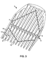
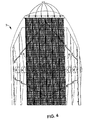
- the balls are separated from the fluid by a filtration device 2 which comprises at least one filtering grid 3 mounted obliquely in the duct 1. More precisely, in accordance with the embodiment illustrated in the figures, the filtration device 2 comprises two grids 3 vis-à-vis mounted obliquely in the conduit 1 to jointly form a funnel separating the balls of the fluid and the guide to a recycling device (not shown) which reinjects the balls upstream of the heat exchanger.
- Each grid 3 comprises a plurality of equidistant parallel beams 4, mounted on a common pivot axis 5, perpendicular to the longitudinal members 4 and rotatably mounted by each of its ends 6, 7, in two bearings 8 formed by substantially diametrically opposed holes practiced. in the wall of the duct 1.
- the spars 4 are in the form of metal blades (made, in practice, stainless steel) which have a rectilinear upstream edge 9, and a curved downstream edge 10, bulged at the passage of the axis 5. Two adjacent spars define between them a corridor 11 with a substantially rectangular contour. In each corridor 11 is mounted a filter element 12 reported.
- Each filter element 12 comprises a plurality of metal strips 13 parallel to each other and to longitudinal members 4, and whose spacing is less than the diameter of the balls, and a plurality of metal supports 14 arranged parallel to each other and perpendicular to the lamellae 13, and on which they are fixed.
- each support 14 is in the form of a single piece having a U-shaped profile, comprising a central core 15, which extends parallel to the axis 5, extended on either side by two legs 16, 17 substantially perpendicular to both the core 15 and the lamellae 13.
- each support 14 is shaped by folding from a straight metal part.
- the lamellae 13 are fixed to the supports 14 by welding. More precisely, as is visible on the figure 6 , the lamellae 13 have a triangular section in section, and have a flat upstream edge 18, and a sharp downstream edge 19, so as to limit the pressure drops during the passage of the fluid.
- the slats 13 are fixed to the supports 14 by their downstream edge 19, which is welded to a rib 20 projecting from an outer edge 21 - or leading edge - of each support 14.
- the lamellae 13 are not only welded to the web 15 of the supports 14: in fact, a first series of lamellae 13 is welded to the webs 15 of the supports 14, and two other series of lamellae 13 are welded, from both sides. Another of the webs 15, to the legs 16, 17.
- the slats 13 of these last two series thus form, together with the legs 16, 17 corresponding, cheeks 22, 23 through which the filter element 12 is fixed to the longitudinal members 4. Washers (not shown) can be welded on the cheeks 22, 23 for supporting fastening bolt heads passing through the longitudinal members 4.
- a filter element 12 of the type described above has the advantage of simplicity of manufacture, while having a mechanical strength equivalent to that of the known filter elements made of steel.
Landscapes
- Engineering & Computer Science (AREA)
- Chemical & Material Sciences (AREA)
- Combustion & Propulsion (AREA)
- Mechanical Engineering (AREA)
- General Engineering & Computer Science (AREA)
- Heat-Exchange Devices With Radiators And Conduit Assemblies (AREA)
- Filtering Materials (AREA)
- Filtering Of Dispersed Particles In Gases (AREA)
- Electrical Discharge Machining, Electrochemical Machining, And Combined Machining (AREA)
Claims (9)
- Filtergitter (3), das dazu bestimmt ist, von einem Wärmetauscher kommende Reinigungskörper von einem Trägerfluid zu trennen, wobei dieses Gitter (3) mehrere parallele Längsträger (4) in gleichem Abstand zueinander, die auf einer gemeinsamen Drehachse (5) lotrecht zu den Längsträgern (4) montiert sind, und mehrere Filterelemente (12) aufweist, die jeweils enthalten:- mehrere parallele Metalllamellen (13), und- mehrere Metallträger (14), die parallel zueinander und lotrecht zu den Lamellen (13) angeordnet sind, und an denen diese befestigt sind,dadurch gekennzeichnet, dass jeder Träger (14) ein einstückiges Bauteil mit einem U-Profil ist, das einen Mittelteil (15) aufweist, der auf beiden Seiten von zwei Schenkeln (16) verlängert ist, die im Wesentlichen lotrecht zu dem Mittelteil (15) sind.
- Filtergitter nach Anspruch 1, dadurch gekennzeichnet, dass jeder Träger (14) eines Filterelements (12) durch Biegen ausgehend von einem geraden Metallbauteil in Form gebracht wird.
- Filtergitter nach Anspruch 1 oder 2, dadurch gekennzeichnet, dass die Lamellen (13) eines Filterelements (12) an die Träger (14) geschweißt sind.
- Filtergitter nach Anspruch 3, dadurch gekennzeichnet, dass eine erste Reihe von Lamellen (13) eines Filterelements (12) an die Mittelteile (15) der Träger (14) geschweißt ist, und dass zwei andere Reihen von Lamellen (13) an die Schenkel (16) der Träger (14) geschweißt sind.
- Filtergitter (3) nach einem der Ansprüche 1 bis 4, dadurch gekennzeichnet, dass die Lamellen (13) eines Filterelements (12) im Schnitt ein dreieckiges Profil haben und eine flache Vorderkante (18) und eine spitze Hinterkante (19) aufweisen.
- Filtergitter nach Anspruch 3 oder 4 in Kombination mit Anspruch 5, dadurch gekennzeichnet, dass die Lamellen (13) eines Filterelements (12) über ihre Hinterkante (19) auf die Träger (14) geschweißt sind.
- Filtergitter nach Anspruch 6, dadurch gekennzeichnet, dass jeder Träger (14) eines Filterelements (12) eine an einem Außenrand (21) vorstehende Rippe (20) aufweist, auf die die Lamellen (13) geschweißt sind.
- Verfahren zur Herstellung eines Filtergitters nach einem der Ansprüche 3 bis 7, das die Schritte aufweist, die darin bestehen:a) Filterelemente (12) bereitzustellen, die jeweils hergestellt werden, indem mehrere Metalllamellen (13) sowie mehrere Träger (14) in Form von geraden Metallbauteilen bereitgestellt werden, und indem die zwei folgenden Teilschritte durchgeführt werden:- Schweißen der parallel zueinander angeordneten Lamellen (13) an die parallel zueinander und lotrecht zu den Lamellen (13) angeordneten Träger (14),- U-förmiges Umbiegen der Träger (14), damit jeder Träger einen Mittelteil (15) aufweist, der auf beiden Seiten von zwei Schenkeln (16) im Wesentlichen lotrecht zum Mittelteil (15) verlängert ist;b) mehrere parallele und einen gleichmäßigen Abstand aufweisende Längsträger (4) auf eine gemeinsame Drehachse (5) lotrecht zu den Längsträgern (4) so zu montieren, dass zwei benachbarte Längsträger zwischen sich einen Durchgang (11) mit im Wesentlichen rechteckigem Umriss definieren;c) ein aufgesetztes Filterelement (12) in jeden Durchgang (11) zu montieren.
- Vorrichtung (2) zum Trennen der von einem Wärmetauscher kommenden Reinigungskörper von einem Trägerfluid, wobei diese Vorrichtung ein Ableitungsrohr (1) und schräg in dieses eingebaut mindestens ein Filtergitter (3) nach einem der Ansprüche 1 bis 7 aufweist.
Applications Claiming Priority (1)
| Application Number | Priority Date | Filing Date | Title |
|---|---|---|---|
| FR0510668A FR2892185B1 (fr) | 2005-10-19 | 2005-10-19 | Element filtrant pour une grille de filtration destinee a separer d'un fluide porteur des corps nettoyants provenant d'un echangeur thermique. |
Publications (2)
| Publication Number | Publication Date |
|---|---|
| EP1777482A1 EP1777482A1 (de) | 2007-04-25 |
| EP1777482B1 true EP1777482B1 (de) | 2009-01-21 |
Family
ID=36648818
Family Applications (1)
| Application Number | Title | Priority Date | Filing Date |
|---|---|---|---|
| EP06291623A Not-in-force EP1777482B1 (de) | 2005-10-19 | 2006-10-18 | Filtergitter zur Trennung von Reinigungskörpern aus der Trägerflüssigkeit eines Wärmetauschers |
Country Status (5)
| Country | Link |
|---|---|
| EP (1) | EP1777482B1 (de) |
| AT (1) | ATE421672T1 (de) |
| DE (1) | DE602006004940D1 (de) |
| ES (1) | ES2321441T3 (de) |
| FR (1) | FR2892185B1 (de) |
Family Cites Families (5)
| Publication number | Priority date | Publication date | Assignee | Title |
|---|---|---|---|---|
| NL186273C (nl) * | 1983-06-30 | 1990-10-16 | Ishikawajima Harima Heavy Ind | Inrichting voor het reinigen van de in hoofdzaak in horizontale richting lopende, buizen van een warmtewisselaar. |
| FR2634600B1 (fr) * | 1988-07-20 | 1990-09-28 | Metal Deploye | Chemin de cables realise avec un treillis de fils metalliques soudes |
| FR2804253B1 (fr) * | 2000-01-24 | 2002-05-10 | Krieg & Zivy Ind | Chemin de cables en fils a haute resistance |
| FR2811072B1 (fr) * | 2000-07-03 | 2002-10-18 | Beaudrey C S | Grille pour intercepter des elements solides mis en circulation dans un echangeur de chaleur pour le nettoyage de celui-ci, et installation de gestion de tels elements comportant une telle grille |
| FR2815548B1 (fr) * | 2000-10-25 | 2003-08-15 | Technos Et Cie | Grille de separation pour separer des corps nettoyants d'un fluide et dispositif comprenant une telle grille |
-
2005
- 2005-10-19 FR FR0510668A patent/FR2892185B1/fr not_active Expired - Fee Related
-
2006
- 2006-10-18 ES ES06291623T patent/ES2321441T3/es active Active
- 2006-10-18 AT AT06291623T patent/ATE421672T1/de not_active IP Right Cessation
- 2006-10-18 EP EP06291623A patent/EP1777482B1/de not_active Not-in-force
- 2006-10-18 DE DE602006004940T patent/DE602006004940D1/de active Active
Also Published As
| Publication number | Publication date |
|---|---|
| DE602006004940D1 (de) | 2009-03-12 |
| EP1777482A1 (de) | 2007-04-25 |
| FR2892185B1 (fr) | 2008-12-26 |
| FR2892185A1 (fr) | 2007-04-20 |
| ATE421672T1 (de) | 2009-02-15 |
| ES2321441T3 (es) | 2009-06-05 |
Similar Documents
| Publication | Publication Date | Title |
|---|---|---|
| EP2715268B1 (de) | Sammelkasten, wärmetauscher mit diesem sammelkasten und verfahren zum bördeln eines derartigen kastens | |
| EP1703243B1 (de) | Wärmetauscher mit Rohren und Rippen sowie Herstellungsverfahren | |
| FR2831253A1 (fr) | Echangeur de chaleur de gaz d'echappement | |
| CN112351828A (zh) | 脉冲喷射式过滤器的低阻力笼 | |
| CH184564A (fr) | Echangeur thermique. | |
| EP1459030A1 (de) | Kreislaufelement für wärmetauscher, insbesondere für ein kraftfahrzeug, und damit hergestellter wärmetauscher | |
| EP1777482B1 (de) | Filtergitter zur Trennung von Reinigungskörpern aus der Trägerflüssigkeit eines Wärmetauschers | |
| FR2866104A1 (fr) | Ailette metallique pour echangeur thermique a air | |
| EP2100800A1 (de) | Schmutzfänger-Schutz für Nutzfahrzeuge | |
| CN203663634U (zh) | 一种烟气除雾装置及除雾元件夹持件 | |
| EP0686823B1 (de) | Wärmetauscher, insbesondere für die Kühlung eines Luftstromes mit hoher Temperatur | |
| WO2015114101A1 (fr) | Echangeur de chaleur pour véhicule automobile | |
| JP4729557B2 (ja) | スートブロワ・フレーム・アセンブリ | |
| WO2013174785A1 (fr) | Intercalaire pour echangeur thermique et echangeur thermique associe | |
| DE2615884A1 (de) | Einbauluefter mit filtermatte | |
| EP2878908B1 (de) | Luftaufbereitungsanlage, die einen Luft-Doppelluftstrom-Tauscher umfasst | |
| EP2852803B1 (de) | Wärmetauscherrohr, wärmetauscherrohrbündel und wärmetauscher mit derartigem bündel | |
| WO2005100901A1 (fr) | Tubes d'echangeur de chaleur favorisant le drainage des condensats | |
| EP1333903A1 (de) | Trenngitter zum abtrennen von reinigungskörpern aus einem fluid und vorrichtung mit einem solchen trenngitter | |
| EP2445377B1 (de) | Gekühltes gehäuse | |
| EP1777481A1 (de) | Trenngitter zum Abscheiden von Reinigungskörpern aus einem Trägerfluid eines Wärmetauschers | |
| DE1900732A1 (de) | Aus Rohren oder Rohrbuendeln bestehender Oberflaechen-Kondensator bzw.Oberflaechen-Waermeaustauscher | |
| CN215031848U (zh) | 一种铜杆表面清理装置 | |
| EP2060420B1 (de) | Wärmeaustauschvorrichtung mit Kältespeicherung | |
| CN212431287U (zh) | 推拉式储水槽转移车 |
Legal Events
| Date | Code | Title | Description |
|---|---|---|---|
| PUAI | Public reference made under article 153(3) epc to a published international application that has entered the european phase |
Free format text: ORIGINAL CODE: 0009012 |
|
| AK | Designated contracting states |
Kind code of ref document: A1 Designated state(s): AT BE BG CH CY CZ DE DK EE ES FI FR GB GR HU IE IS IT LI LT LU LV MC NL PL PT RO SE SI SK TR |
|
| AX | Request for extension of the european patent |
Extension state: AL BA HR MK YU |
|
| 17P | Request for examination filed |
Effective date: 20071024 |
|
| AKX | Designation fees paid |
Designated state(s): AT BE BG CH CY CZ DE DK EE ES FI FR GB GR HU IE IS IT LI LT LU LV MC NL PL PT RO SE SI SK TR |
|
| 17Q | First examination report despatched |
Effective date: 20080117 |
|
| GRAP | Despatch of communication of intention to grant a patent |
Free format text: ORIGINAL CODE: EPIDOSNIGR1 |
|
| GRAS | Grant fee paid |
Free format text: ORIGINAL CODE: EPIDOSNIGR3 |
|
| GRAA | (expected) grant |
Free format text: ORIGINAL CODE: 0009210 |
|
| AK | Designated contracting states |
Kind code of ref document: B1 Designated state(s): AT BE BG CH CY CZ DE DK EE ES FI FR GB GR HU IE IS IT LI LT LU LV MC NL PL PT RO SE SI SK TR |
|
| REG | Reference to a national code |
Ref country code: GB Ref legal event code: FG4D Free format text: NOT ENGLISH |
|
| REG | Reference to a national code |
Ref country code: CH Ref legal event code: EP |
|
| REG | Reference to a national code |
Ref country code: IE Ref legal event code: FG4D Free format text: LANGUAGE OF EP DOCUMENT: FRENCH |
|
| REF | Corresponds to: |
Ref document number: 602006004940 Country of ref document: DE Date of ref document: 20090312 Kind code of ref document: P |
|
| PG25 | Lapsed in a contracting state [announced via postgrant information from national office to epo] |
Ref country code: NL Free format text: LAPSE BECAUSE OF FAILURE TO SUBMIT A TRANSLATION OF THE DESCRIPTION OR TO PAY THE FEE WITHIN THE PRESCRIBED TIME-LIMIT Effective date: 20090121 |
|
| REG | Reference to a national code |
Ref country code: ES Ref legal event code: FG2A Ref document number: 2321441 Country of ref document: ES Kind code of ref document: T3 |
|
| NLV1 | Nl: lapsed or annulled due to failure to fulfill the requirements of art. 29p and 29m of the patents act | ||
| PG25 | Lapsed in a contracting state [announced via postgrant information from national office to epo] |
Ref country code: FI Free format text: LAPSE BECAUSE OF FAILURE TO SUBMIT A TRANSLATION OF THE DESCRIPTION OR TO PAY THE FEE WITHIN THE PRESCRIBED TIME-LIMIT Effective date: 20090121 Ref country code: LT Free format text: LAPSE BECAUSE OF FAILURE TO SUBMIT A TRANSLATION OF THE DESCRIPTION OR TO PAY THE FEE WITHIN THE PRESCRIBED TIME-LIMIT Effective date: 20090121 Ref country code: SI Free format text: LAPSE BECAUSE OF FAILURE TO SUBMIT A TRANSLATION OF THE DESCRIPTION OR TO PAY THE FEE WITHIN THE PRESCRIBED TIME-LIMIT Effective date: 20090121 |
|
| REG | Reference to a national code |
Ref country code: IE Ref legal event code: FD4D |
|
| PG25 | Lapsed in a contracting state [announced via postgrant information from national office to epo] |
Ref country code: PL Free format text: LAPSE BECAUSE OF FAILURE TO SUBMIT A TRANSLATION OF THE DESCRIPTION OR TO PAY THE FEE WITHIN THE PRESCRIBED TIME-LIMIT Effective date: 20090121 Ref country code: LV Free format text: LAPSE BECAUSE OF FAILURE TO SUBMIT A TRANSLATION OF THE DESCRIPTION OR TO PAY THE FEE WITHIN THE PRESCRIBED TIME-LIMIT Effective date: 20090121 Ref country code: IS Free format text: LAPSE BECAUSE OF FAILURE TO SUBMIT A TRANSLATION OF THE DESCRIPTION OR TO PAY THE FEE WITHIN THE PRESCRIBED TIME-LIMIT Effective date: 20090521 Ref country code: PT Free format text: LAPSE BECAUSE OF FAILURE TO SUBMIT A TRANSLATION OF THE DESCRIPTION OR TO PAY THE FEE WITHIN THE PRESCRIBED TIME-LIMIT Effective date: 20090622 Ref country code: SE Free format text: LAPSE BECAUSE OF FAILURE TO SUBMIT A TRANSLATION OF THE DESCRIPTION OR TO PAY THE FEE WITHIN THE PRESCRIBED TIME-LIMIT Effective date: 20090421 Ref country code: AT Free format text: LAPSE BECAUSE OF FAILURE TO SUBMIT A TRANSLATION OF THE DESCRIPTION OR TO PAY THE FEE WITHIN THE PRESCRIBED TIME-LIMIT Effective date: 20090121 |
|
| REG | Reference to a national code |
Ref country code: HU Ref legal event code: AG4A Ref document number: E005580 Country of ref document: HU |
|
| PG25 | Lapsed in a contracting state [announced via postgrant information from national office to epo] |
Ref country code: CZ Free format text: LAPSE BECAUSE OF FAILURE TO SUBMIT A TRANSLATION OF THE DESCRIPTION OR TO PAY THE FEE WITHIN THE PRESCRIBED TIME-LIMIT Effective date: 20090121 Ref country code: IE Free format text: LAPSE BECAUSE OF FAILURE TO SUBMIT A TRANSLATION OF THE DESCRIPTION OR TO PAY THE FEE WITHIN THE PRESCRIBED TIME-LIMIT Effective date: 20090121 Ref country code: DK Free format text: LAPSE BECAUSE OF FAILURE TO SUBMIT A TRANSLATION OF THE DESCRIPTION OR TO PAY THE FEE WITHIN THE PRESCRIBED TIME-LIMIT Effective date: 20090121 Ref country code: EE Free format text: LAPSE BECAUSE OF FAILURE TO SUBMIT A TRANSLATION OF THE DESCRIPTION OR TO PAY THE FEE WITHIN THE PRESCRIBED TIME-LIMIT Effective date: 20090121 |
|
| PLBE | No opposition filed within time limit |
Free format text: ORIGINAL CODE: 0009261 |
|
| STAA | Information on the status of an ep patent application or granted ep patent |
Free format text: STATUS: NO OPPOSITION FILED WITHIN TIME LIMIT |
|
| PG25 | Lapsed in a contracting state [announced via postgrant information from national office to epo] |
Ref country code: SK Free format text: LAPSE BECAUSE OF FAILURE TO SUBMIT A TRANSLATION OF THE DESCRIPTION OR TO PAY THE FEE WITHIN THE PRESCRIBED TIME-LIMIT Effective date: 20090121 Ref country code: RO Free format text: LAPSE BECAUSE OF FAILURE TO SUBMIT A TRANSLATION OF THE DESCRIPTION OR TO PAY THE FEE WITHIN THE PRESCRIBED TIME-LIMIT Effective date: 20090121 |
|
| 26N | No opposition filed |
Effective date: 20091022 |
|
| PG25 | Lapsed in a contracting state [announced via postgrant information from national office to epo] |
Ref country code: BG Free format text: LAPSE BECAUSE OF FAILURE TO SUBMIT A TRANSLATION OF THE DESCRIPTION OR TO PAY THE FEE WITHIN THE PRESCRIBED TIME-LIMIT Effective date: 20090421 |
|
| PGFP | Annual fee paid to national office [announced via postgrant information from national office to epo] |
Ref country code: ES Payment date: 20091027 Year of fee payment: 4 Ref country code: HU Payment date: 20091008 Year of fee payment: 4 |
|
| PGFP | Annual fee paid to national office [announced via postgrant information from national office to epo] |
Ref country code: IT Payment date: 20091031 Year of fee payment: 4 |
|
| PG25 | Lapsed in a contracting state [announced via postgrant information from national office to epo] |
Ref country code: MC Free format text: LAPSE BECAUSE OF NON-PAYMENT OF DUE FEES Effective date: 20091031 |
|
| PGFP | Annual fee paid to national office [announced via postgrant information from national office to epo] |
Ref country code: BE Payment date: 20091130 Year of fee payment: 4 |
|
| PG25 | Lapsed in a contracting state [announced via postgrant information from national office to epo] |
Ref country code: GR Free format text: LAPSE BECAUSE OF FAILURE TO SUBMIT A TRANSLATION OF THE DESCRIPTION OR TO PAY THE FEE WITHIN THE PRESCRIBED TIME-LIMIT Effective date: 20090422 |
|
| PGFP | Annual fee paid to national office [announced via postgrant information from national office to epo] |
Ref country code: FR Payment date: 20101110 Year of fee payment: 5 |
|
| PGFP | Annual fee paid to national office [announced via postgrant information from national office to epo] |
Ref country code: DE Payment date: 20101012 Year of fee payment: 5 |
|
| PG25 | Lapsed in a contracting state [announced via postgrant information from national office to epo] |
Ref country code: LU Free format text: LAPSE BECAUSE OF NON-PAYMENT OF DUE FEES Effective date: 20091018 |
|
| BERE | Be: lapsed |
Owner name: TECHNOS ET CIE Effective date: 20101031 |
|
| REG | Reference to a national code |
Ref country code: CH Ref legal event code: PL |
|
| GBPC | Gb: european patent ceased through non-payment of renewal fee |
Effective date: 20101018 |
|
| PG25 | Lapsed in a contracting state [announced via postgrant information from national office to epo] |
Ref country code: LI Free format text: LAPSE BECAUSE OF NON-PAYMENT OF DUE FEES Effective date: 20101031 Ref country code: CH Free format text: LAPSE BECAUSE OF NON-PAYMENT OF DUE FEES Effective date: 20101031 Ref country code: HU Free format text: LAPSE BECAUSE OF NON-PAYMENT OF DUE FEES Effective date: 20101019 |
|
| PG25 | Lapsed in a contracting state [announced via postgrant information from national office to epo] |
Ref country code: TR Free format text: LAPSE BECAUSE OF FAILURE TO SUBMIT A TRANSLATION OF THE DESCRIPTION OR TO PAY THE FEE WITHIN THE PRESCRIBED TIME-LIMIT Effective date: 20090121 Ref country code: GB Free format text: LAPSE BECAUSE OF NON-PAYMENT OF DUE FEES Effective date: 20101018 Ref country code: BE Free format text: LAPSE BECAUSE OF NON-PAYMENT OF DUE FEES Effective date: 20101031 |
|
| PG25 | Lapsed in a contracting state [announced via postgrant information from national office to epo] |
Ref country code: CY Free format text: LAPSE BECAUSE OF FAILURE TO SUBMIT A TRANSLATION OF THE DESCRIPTION OR TO PAY THE FEE WITHIN THE PRESCRIBED TIME-LIMIT Effective date: 20090121 |
|
| REG | Reference to a national code |
Ref country code: ES Ref legal event code: FD2A Effective date: 20111118 |
|
| PG25 | Lapsed in a contracting state [announced via postgrant information from national office to epo] |
Ref country code: IT Free format text: LAPSE BECAUSE OF NON-PAYMENT OF DUE FEES Effective date: 20101018 |
|
| PG25 | Lapsed in a contracting state [announced via postgrant information from national office to epo] |
Ref country code: ES Free format text: LAPSE BECAUSE OF NON-PAYMENT OF DUE FEES Effective date: 20101019 |
|
| REG | Reference to a national code |
Ref country code: FR Ref legal event code: ST Effective date: 20120629 |
|
| PG25 | Lapsed in a contracting state [announced via postgrant information from national office to epo] |
Ref country code: DE Free format text: LAPSE BECAUSE OF NON-PAYMENT OF DUE FEES Effective date: 20120501 |
|
| REG | Reference to a national code |
Ref country code: DE Ref legal event code: R119 Ref document number: 602006004940 Country of ref document: DE Effective date: 20120501 |
|
| PG25 | Lapsed in a contracting state [announced via postgrant information from national office to epo] |
Ref country code: FR Free format text: LAPSE BECAUSE OF NON-PAYMENT OF DUE FEES Effective date: 20111102 |