EP1777131A2 - Bremshebelanordnung für Feststellbremse - Google Patents
Bremshebelanordnung für Feststellbremse Download PDFInfo
- Publication number
- EP1777131A2 EP1777131A2 EP06020717A EP06020717A EP1777131A2 EP 1777131 A2 EP1777131 A2 EP 1777131A2 EP 06020717 A EP06020717 A EP 06020717A EP 06020717 A EP06020717 A EP 06020717A EP 1777131 A2 EP1777131 A2 EP 1777131A2
- Authority
- EP
- European Patent Office
- Prior art keywords
- brake lever
- brake
- axis
- driver
- lever
- Prior art date
- Legal status (The legal status is an assumption and is not a legal conclusion. Google has not performed a legal analysis and makes no representation as to the accuracy of the status listed.)
- Granted
Links
- 230000008878 coupling Effects 0.000 claims description 17
- 238000010168 coupling process Methods 0.000 claims description 17
- 238000005859 coupling reaction Methods 0.000 claims description 17
- 238000004519 manufacturing process Methods 0.000 description 3
- 230000005540 biological transmission Effects 0.000 description 2
- 230000000712 assembly Effects 0.000 description 1
- 238000000429 assembly Methods 0.000 description 1
- 238000006073 displacement reaction Methods 0.000 description 1
- 238000005553 drilling Methods 0.000 description 1
Images
Classifications
-
- B—PERFORMING OPERATIONS; TRANSPORTING
- B60—VEHICLES IN GENERAL
- B60T—VEHICLE BRAKE CONTROL SYSTEMS OR PARTS THEREOF; BRAKE CONTROL SYSTEMS OR PARTS THEREOF, IN GENERAL; ARRANGEMENT OF BRAKING ELEMENTS ON VEHICLES IN GENERAL; PORTABLE DEVICES FOR PREVENTING UNWANTED MOVEMENT OF VEHICLES; VEHICLE MODIFICATIONS TO FACILITATE COOLING OF BRAKES
- B60T7/00—Brake-action initiating means
- B60T7/02—Brake-action initiating means for personal initiation
- B60T7/08—Brake-action initiating means for personal initiation hand actuated
- B60T7/10—Disposition of hand control
- B60T7/102—Disposition of hand control by means of a tilting lever
Definitions
- the present invention is in the technical field of parking brakes for motor vehicles and relates to a brake lever assembly for a parking brake in a motor vehicle according to the preamble of claim 1.
- the hand brake lever in an off-center position and to provide the Bremszugabgang in the middle of the vehicle.
- a driver axle projecting laterally from the handbrake lever is provided for the brake cable, which is rotatably mounted at its two ends in respective rotary bearings and rigidly connected to the handbrake lever.
- the object of the present invention is to provide a brake lever assembly for a parking brake of a motor vehicle available, with which the aforementioned disadvantage of high material and manufacturing costs can be avoided.
- a brake lever arrangement for a parking brake of a motor vehicle which comprises a brake lever for manual actuation of at least one wheel brake and a rotatably mounted driver axle for a brake cable, by which tensile forces can be transmitted to the wheel brake.
- the brake lever is in this case rotatably coupled to the driver axis in the direction of rotation of the driver axis.
- the brake lever assembly according to the invention is characterized in an essential way by the fact that the brake lever is coupled by means of a displaceable in the direction of the driving axis, positive connection with the driving axle.
- the brake lever and the driver axis by the decoupling of the brake lever and the driver axis in the direction of the driver axis a transmission directed perpendicular to the pivot plane of the brake lever on the brake lever acting forces are avoided on the driving axle.
- the drive axle and its pivot bearings which are therefore exposed to much lower loads and only transmit the necessary to wind the brake cable torque, and must absorb the forces resulting from the brake drag forces in the pivot bearings can thus be made less stable, which material costs can be saved.
- a tilting game and associated noise do not occur, so that the accuracy of fit can be reduced accordingly, which reduces the manufacturing cost.
- the positive connection between the brake lever and the driver axis is rotationally fixed in the direction of rotation of the driver axis.
- a non-rotatable embodiment of the positive connection viewed in cross section in the pivoting plane of the brake lever, by a non-circular shape, such as a quadrangular, triangular or star-shaped, can be achieved with matching counter-shape of the positive connection between the brake lever and drive axle.
- the positive connection between the brake lever and the driver axis in the direction of rotation of the driver axis is rotatable, which, viewed in cross section in the pivot plane of the brake lever is achieved by a round shape with matching counter-shape of the positive connection between the brake lever and driver axis ,
- a coupling mechanism for the rotationally fixed coupling of the brake lever and driving axle is additionally formed.
- Modern motor vehicles are usually equipped with an adjusting device for the parking brake, by which the distance ("air gap") between brake pad and brake drum or brake disc readjusted (reduced) can, as the air play gradually increases during use of a motor vehicle due to wear of the brake friction exposed components and an elongation of the brake cable.
- an adjusting device for the parking brake by which the distance ("air gap") between brake pad and brake drum or brake disc readjusted (reduced) can, as the air play gradually increases during use of a motor vehicle due to wear of the brake friction exposed components and an elongation of the brake cable.
- manual adjusting devices are installed in motor vehicles, in which the brake cable is connected to a threaded rod which engages in a connected to the brake lever nut, so that by screwing the threaded rod in the nut, the effective for power transmission, effective length of the brake cable can be shortened.
- a disadvantage of such adjusting devices for the air clearance in generic brake lever assemblies is in particular the fact that a hole in the center console or in the vehicle underbody must be provided to operate the adjuster.
- the coupling mechanism for the rotationally fixed coupling of the brake lever and driving axle is provided with a clearance adjusting mechanism for rotating the driving axle relative to the brake lever, so that dispensing with the attachment of a hole in the center console or in the vehicle underbody can.
- the brake lever assembly according to the invention is advantageously provided with a arranged in the pivot plane of the brake lever and immersed in a recess of the brake lever support member for supporting the brake lever in the direction of the driving axis through which directed perpendicular to the pivot plane of the brake lever, acting on the brake lever forces can be absorbed.
- the invention further extends to a parking brake of a motor vehicle, which comprises a brake lever assembly as described above. Furthermore, the extends Invention on a motor vehicle, which is equipped with such a parking brake.
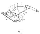
- a brake lever assembly according to the invention for a parking brake is shown.
- a brake lever assembly according to the invention comprises a brake lever 1 and a driving axle 2, which is rotatably mounted on the pivot bearings 3, 4.
- the pivot bearings 3, 4 are in this case formed on respective bearing blocks 5, 6, which in turn are attached to a base plate connected to the vehicle floor 7.
- the hand brake lever 1 is connected to the driver axis 2 by means of a positive connection 8, which has a round shape in section in the pivot plane of the brake lever 1 and thus is rotatable.
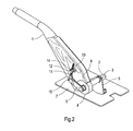
- a coupling mechanism shown in Fig. 2 is provided for the rotationally fixed coupling between the brake lever 1 and driving axle 2.
- the coupling mechanism comprises a coupling rod 9 rotatably connected to the driving axle 1, which is articulated to a threaded rod 11 by means of a pivoting joint 10.
- the threaded rod 11 is in turn guided by the hole of a piercing bolt 12 which is rotatably inserted into a corresponding bore 13 in the brake lever 1 with respect to a rotational axis parallel to the driving axis.
- the threaded rod is on the other Side of the piercer bolt 12 secured by a nut 14.
- the coupling mechanism is an air gap adjusting device for the parking brake, since, with respect to the direction of rotation of the driver axis 2, the relative position of the brake lever to the driver axis 2 by tightening or loosening the nut 14 can be changed. In other words, by tightening or loosening the nut 14, the brake lever 1 can be rotated relative to the Mitmehmerachse 2. Due to the articulated connection of coupling rod 4 and threaded rod 11, as well as by the rotatable mounting of the piercing bolt 12 in the bore 13 of the brake lever 1, such a rotation of the brake lever 1 relative to the driving axis 2 is easily possible. On the provision of a hole in the center console or the vehicle underbody to operate a clearance adjustment device can thus be advantageously dispensed.
- a protruding from the base plate 7 in the pivoting plane of the brake lever 1 support plate 15 is provided, which dives into a formed by the two side plates 15, 16 recess of the brake lever.
- the support plate 15 is thus able to absorb laterally acting on the brake lever forces and to secure the brake lever against lateral displacement.
Landscapes
- Engineering & Computer Science (AREA)
- Transportation (AREA)
- Mechanical Engineering (AREA)
- Braking Arrangements (AREA)
- Braking Elements And Transmission Devices (AREA)
Abstract
Description
- Die vorliegende Erfindung liegt auf dem technischen Gebiet der Feststellbremsen für Kraftfahrzeuge und betrifft eine Bremshebelanordnung für eine Feststellbremse in einem Kraftfahrzeug nach dem Oberbegriff von Anspruch 1.
- In manchen Kraftfahrzeugen ist es praktisch den Handbremshebel in einer außermittigen Position anzuordnen und den Bremszugabgang in der Fahrzeugmitte vorzusehen. Zu diesem Zweck ist im Bereich der Schwenkachse des Handbremshebels eine vom Handbremshebel seitlich abragende Mitnehmerachse für den Bremszug vorgesehen, die an ihren beiden Enden in jeweiligen Drehlagern drehbar gelagert und mit dem Handbremshebel starr verbunden ist.
- Nun hat sich in der Praxis gezeigt, dass die Mitnehmerachse und deren Drehlagerungen durch senkrecht zur Schwenkebene des Bremshebels gerichtete, seitlich auf den Bremshebel einwirkende Kräfte stark belastet und dementsprechend stabil auszulegen sind, um eine Beschädigung zu vermeiden. Solche seitlichen Kräfte können beispielsweise durch eine fehlerhafte Bedienung des Bremshebels auftreten, etwa wenn der Bremshebel nicht genau in Schwenkrichtung gezogen oder gelöst wird, sondern wenn der Bediener schräg am Bremshebel zieht oder drückt. Häufig tritt auch ein ungewolltes seitliches Drücken am Bremshebel auf, wenn sich Fahrer oder Beifahrer zum gegenüberliegenden Sitz neigen und versehentlich den Bremshebel berühren.
- Nachteilig bei einer solchen erforderlichen stabilen Auslegung der Mitnehmerachse und deren Drehlagerungen sind vor allem die damit einher gehenden hohen Materialkosten. Zudem müssen die Drehlager mit einer relativ hohen Genauigkeit gepasst werden, um durch die gegengleiche Belastung der Drehlager Kippspiel und damit einher gehende Geräusche zu vermeiden, was zu vergleichsweise hohen Fertigungskosten führt.
- Demgegenüber besteht die Aufgabe der vorliegenden Erfindung darin, eine Bremshebelanordnung für eine Feststellbremse eines Kraftfahrzeugs zur Verfügung zu stellen, mit welcher der vorgenannte Nachteil hoher Material- und Fertigungkosten vermieden werden kann.
- Diese Aufgabe wird nach dem Vorschlag der Erfindung durch eine Bremshebelanordnung für eine Feststellbremse eines Kraftfahrzeugs mit den Merkmalen des unabhängigen Anspruchs gelöst. Vorteilhafte Ausgestaltungen der Erfindung sind durch die Merkmale der Unteransprüche angegeben.
- Erfindungsgemäß ist eine Bremshebelanordnung für eine Feststellbremse eines Kraftfahrzeugs gezeigt, welche einen Bremshebel zur manuellen Betätigung wenigstens einer Radbremse und eine drehbar gelagerte Mitnehmerachse für einen Bremszug, durch welchen Zugkräfte auf die Radbremse übertragen werden können, umfasst. Der Bremshebel ist hierbei mit der Mitnehmerachse in Drehrichtung der Mitnehmerachse drehfest gekoppelt.
- Die erfindungsgemäße Bremshebelanordnung zeichnet sich in wesentlicher Weise dadurch aus, dass der Bremshebel mittels einer in Richtung der Mitnehmerachse verschiebbaren, formschlüssigen Verbindung mit der Mitnehmerachse gekoppelt ist.
- Erfindungsgemäß kann durch die Entkopplung von Bremshebel und Mitnehmerachse in Richtung der Mitnehmerachse eine Übertragung von senkrecht zur Schwenkebene des Bremshebels gerichteten, auf den Bremshebel einwirkenden Kräften auf die Mitnehmerachse vermieden werden. Die Mitnehmerachse und deren Drehlagerungen, die demzufolge wesentlich geringeren Belastungen ausgesetzt sind und lediglich das zum Aufwickeln des Bremszugs notwendige Kraftmoment übertragen, sowie die aus der Bremszugkraft resultierenden Kräfte in den Drehlagerungen aufnehmen müssen, können somit weniger stabil ausgeführt werden, wodurch Materialkosten eingespart werden können. Zudem treten ein Kippspiel und damit einhergehend Geräusche nicht auf, so dass die Passgenauigkeit entsprechend reduziert werden kann, was die Fertigungskosten vermindert.
- Bei einer vorteilhaften Ausgestaltung der Erfindung ist die formschlüssige Verbindung zwischen dem Bremshebel und der Mitnehmerachse in Drehrichtung der Mitnehmerachse drehfest ausgeführt. Eine solche drehfeste Ausführung der formschlüssigen Verbindung kann, im Querschnitt in der Schwenkebene des Bremshebels betrachtet, durch eine nicht-runde Form, beispielsweise eine viereckige, dreieckige oder sternförmige Form, mit passender Gegenform der formschlüssigen Verbindung zwischen Bremshebel und Mitnehmerachse erreicht werden.
- Bei einer alternativen vorteilhaften Ausgestaltung der Erfindung ist die formschlüssige Verbindung zwischen dem Bremshebel und der Mitnehmerachse in Drehrichtung der Mitnehmerachse drehbeweglich, was, im Querschnitt in der Schwenkebene des Bremshebels betrachtet, durch eine runde Form mit passender Gegenform der formschlüssigen Verbindung zwischen Bremshebel und Mitnehmerachse erreicht wird. In diesem Fall ist zusätzlich ein Kopplungsmechanismus zur drehfesten Kopplung von Bremshebel und Mitnehmerachse ausgebildet.
- Moderne Kraftfahrzeuge sind üblicherweise mit einer Nachstellvorrichtung für die Feststellbremse ausgestattet, durch welche der Abstand ("Luftspiel") zwischen Bremsbelag und Bremstrommel bzw. Bremsscheibe nachgestellt (verringert) werden kann, da das Luftspiel während des Gebrauchs eines Kraftfahrzeugs aufgrund von Verschleiß von der Bremsreibung ausgesetzten Bauteilen sowie einer Längung des Bremszugs allmählich zunimmt. Zur Nachstellung des Lüftspiels von Feststellbremsen werden in Kraftfahrzeugen beispielsweise manuelle Nachstellvorrichtungen eingebaut, bei denen der Bremszug mit einer Gewindestange verbunden ist, welche in eine mit dem Bremshebel verbundene Schraubenmutter greift, so dass durch ein Eindrehen der Gewindestange in die Schraubenmutter die für die Kraftübertragung wirksame, effektive Länge des Bremszugs verkürzt werden kann.
- Nachteilig bei solchen Nachstellvorrichtungen für das Luftspiel in gattungsgemäßen Bremshebelanordnungen ist insbesondere die Tatsache, dass zur Bedienung der Nachstellvorrichtung ein Loch in der Mittelkonsole oder im Fahrzeugunterboden vorgesehen werden muss.
- Zur Vermeidung dieses Nachteils ist gemäß einer besonders vorteilhaften Ausgestaltung der Erfindung der Kopplungsmechanismus zur drehfesten Kopplung von Bremshebel und Mitnehmerachse mit einem Lüftspiel-Nachstellmechanismus zum Verdrehen der Mitnehmerachse relativ zum Bremshebel versehen, so dass auf das Anbringen eines Lochs in der Mittelkonsole oder im Fahrzeugunterboden verzichtet werden kann.
- Weiterhin ist die erfindungsgemäße Bremshebelanordnung vorteilhaft mit einem in der Schwenkebene des Bremshebels angeordneten und in eine Ausnehmung des Bremshebels eingetauchten Stützelement zum Abstützen des Bremshebels in Richtung der Mitnehmerachse versehen, durch welches senkrecht zur Schwenkebene des Bremshebels gerichtete, auf den Bremshebel einwirkende Kräfte aufgenommen werden können.
- Die Erfindung erstreckt sich ferner auf eine Feststellbremse eines Kraftfahrzeugs, welche eine wie oben beschriebene Bremshebelanordnung umfasst. Weiterhin erstreckt sich die Erfindung auf ein Kraftfahrzeug, das mit einer solchen Feststellbremse ausgerüstet ist.
- Die Erfindung wird nun anhand eines Ausführungsbeispiels näher erläutert, wobei Bezug auf die beigefügten Zeichnungen genommen wird. Es zeigen
- Fig. 1
- eine schematische perspektivische Ansicht einer Ausführungsform einer erfindungsgemäßen Bremshebelanordnung für eine Feststellbremse;
- Fig. 2
- eine weitere schematische perspektivische Ansicht der Ausführungsform einer erfindungsgemäßen Nachstellvorrichtung für eine Feststellbremse von Fig. 1.
- In den beigefügten Figuren ist eine Ausführungsform einer erfindungsgemäßen Bremshebelanordnung für eine Feststellbremse dargestellt. Demnach umfasst eine erfindungsgemäße Bremshebelanordnung einen Bremshebel 1 und eine Mitnehmerachse 2, die an den Drehlagern 3, 4 drehbar gelagert ist. Die Drehlager 3, 4 sind hierbei an jeweiligen Lagerböcken 5, 6 geformt, welche ihrerseits an einer mit dem Fahrzeugboden verbundenen Sockelplatte 7 angebracht sind.
- Der Handbremshebel 1 ist mit der Mitnehmerachse 2 mittels einer formschlüssigen Verbindung 8 verbunden, welche im Schnitt in der Schwenkebene des Bremshebels 1 eine runde Form hat und somit drehbeweglich ist. Zur drehfesten Kopplung zwischen Bremshebel 1 und Mitnehmerachse 2 ist ein in Fig. 2 dargestellter Kopplungsmechanismus vorgesehen. Der Kopplungsmechanismus umfasst eine mit der Mitnehmerachse 1 drehfest verbundene Kopplungsstange 9, die mit einer Gewindestange 11 mittels eines Schwenkgelenks 10 gelenkig verbunden ist. Die Gewindestange 11 ist ihrerseits durch das Loch eines Lochbolzens 12 geführt, welcher in eine entsprechende Bohrung 13 im Bremshebel 1 bezüglich einer zur Mitnehmerachse parallelen Drehachse drehbeweglich eingesetzt ist. Die Gewindestange ist auf der anderen Seite des Lochbolzens 12 durch eine Schraubenmutter 14 gesichert. Durch den dargestellten Kopplungsmechanismus kann somit eine drehfeste Kopplung zwischen Bremshebel 1 und Mitnehmerachse 2 erreicht werden, wodurch ein in den Figuren nicht dargestellter Bremszug durch Verschwenken des Bremshebels 1 angezogen oder gelockert werden kann.
- Weiterhin stellt der Kopplungsmechanismus eine Luftspiel-Nachstellvorrichtung für die Feststellbremse dar, da, bezüglich der Drehrichtung der Mitnehmerachse 2, die relative Position des Bremshebels zur Mitnehmerachse 2 durch Anziehen oder Lockern der Schraubenmutter 14 geändert werden kann. Mit anderen Worten kann durch Anziehen oder Lockern der Schraubenmutter 14 der Bremshebel 1 relativ zur Mitmehmerachse 2 verdreht werden. Durch die gelenkige Verbindung von Koppelstange 4 und Gewindestange 11, sowie durch die drehbewegliche Lagerung des Lochbolzens 12 in der Bohrung 13 des Bremshebels 1, ist eine solche Verdrehung des Bremshebels 1 relativ zur Mitnehmerachse 2 problemlos möglich. Auf das Vorsehen eines Lochs in der Mittelkonsole oder dem Fahrzeugunterboden zur Bedienung einer Lüftspiel-Nachstellvorrichtung kann somit vorteilhaft verzichet werden.
- Weiterhin ist eine von der Sockelplatte 7 in der Schwenkebene des Bremshebels 1 abragende Stützplatte 15 vorgesehen, welche in eine durch die beiden Seitenplatten 15, 16 geformte Ausnehmung des Bremshebels taucht. Die Stützplatte 15 ist somit in der Lage seitlich auf den Bremshebel einwirkende Kräfte aufzunehmen und den Bremshebel gegen ein seitliches Verschieben zu sichern.
-
- 1
- Bremshebel
- 2
- Mitnehmerachse
- 3
- Drehlager
- 4
- Drehlager
- 5
- Lagerbock
- 6
- Lagerbock
- 7
- Sockelplatte
- 8
- formschlüssige Verbindung
- 9
- Koppelstange
- 10
- Schwenkgelenk
- 11
- Gewindestange
- 12
- Lochbolzen
- 13
- Bohrung
- 14
- Schraubenmutter
- 15
- Stützplatte
- 16
- Seitenplatte
- 17
- Seitenplatte
Claims (7)
- Bremshebelanordnung für eine Feststellbremse eines Kraftfahrzeugs, welche einen Bremshebel (1) zur manuellen Betätigung wenigstens einer Radbremse und eine drehbar gelagerte Mitnehmerachse (2) für einen Bremszug, durch welchen Zugkräfte auf die Radbremse übertragen werden können, umfasst, wobei der Bremshebel mit der Mitnehmerachse in Drehrichtung der Mitnehmerachse drehfest gekoppelt ist,
dadurch gekennzeichnet, dass der Bremshebel (1) mittels einer in Richtung der Mitnehmerachse verschiebbaren, formschlüssigen Verbindung (8) mit der Mitnehmerachse (2) gekoppelt ist. - Bremshebelanordnung nach Anspruch 1,
dadurch gekennzeichnet, dass die formschlüssige Verbindung zwischen dem Bremshebel und der Mitnehmerachse in Drehrichtung der Mitnehmerachse drehfest ist. - Bremshebelanordnung nach Anspruch 1,
dadurch gekennzeichnet, dass die formschlüssige Verbindung zwischen dem Bremshebel und der Mitnehmerachse in Drehrichtung der Mitnehmerachse drehbeweglich ist, und weiterhin ein Kopplungsmechanismus zur drehfesten Kopplung von Bremshebel und Mitnehmerachse ausgebildet ist. - Bremshebelanordnung nach Anspruch 3,
dadurch gekennzeichnet, dass der Kopplungsmechanismus zur drehfesten Kopplung von Bremshebel und Mitnehmerachse ein Drehung der Mitnehmerachse relativ zum Bremshebel ermöglicht. - Bremshebelanordnung nach einem der Ansprüche 1 bis 4,
gekennzeichnet durch ein in der Schwenkebene des Bremshebels angeordnetes und in eine Ausnehmung des Bremshebels eingetauchtes Stützelement zum Abstützen des Bremshebels in Richtung der Mitnehmerachse. - Feststellbremse eines Kraftfahrzeugs mit einer Bremshebelanordnung nach einem der vorhergehenden Ansprüche 1 bis 5.
- Kraftfahrzeug mit einer Feststellbremse nach Anspruch 6.
Applications Claiming Priority (1)
| Application Number | Priority Date | Filing Date | Title |
|---|---|---|---|
| DE102005049946A DE102005049946A1 (de) | 2005-10-19 | 2005-10-19 | Bremshebelanordnung für Feststellbremse |
Publications (3)
| Publication Number | Publication Date |
|---|---|
| EP1777131A2 true EP1777131A2 (de) | 2007-04-25 |
| EP1777131A3 EP1777131A3 (de) | 2008-10-15 |
| EP1777131B1 EP1777131B1 (de) | 2010-01-20 |
Family
ID=37561025
Family Applications (1)
| Application Number | Title | Priority Date | Filing Date |
|---|---|---|---|
| EP06020717A Not-in-force EP1777131B1 (de) | 2005-10-19 | 2006-10-02 | Bremshebelanordnung für Feststellbremse |
Country Status (3)
| Country | Link |
|---|---|
| EP (1) | EP1777131B1 (de) |
| AT (1) | ATE455684T1 (de) |
| DE (2) | DE102005049946A1 (de) |
Family Cites Families (2)
| Publication number | Priority date | Publication date | Assignee | Title |
|---|---|---|---|---|
| DE4315237A1 (de) * | 1993-05-07 | 1994-11-10 | Hans Pickert | Diebstahlgesicherte Hand- oder Standbremse |
| US5462146A (en) * | 1993-07-06 | 1995-10-31 | Dura Mechanical Components, Inc. | Common shifter and parking brake mounting |
-
2005
- 2005-10-19 DE DE102005049946A patent/DE102005049946A1/de not_active Withdrawn
-
2006
- 2006-10-02 EP EP06020717A patent/EP1777131B1/de not_active Not-in-force
- 2006-10-02 DE DE502006005962T patent/DE502006005962D1/de active Active
- 2006-10-02 AT AT06020717T patent/ATE455684T1/de active
Also Published As
| Publication number | Publication date |
|---|---|
| DE102005049946A1 (de) | 2007-05-24 |
| DE502006005962D1 (de) | 2010-03-11 |
| EP1777131A3 (de) | 2008-10-15 |
| EP1777131B1 (de) | 2010-01-20 |
| ATE455684T1 (de) | 2010-02-15 |
Similar Documents
| Publication | Publication Date | Title |
|---|---|---|
| EP3149353B2 (de) | Scheibenbremse, bremssattel und bremsbelagsatz für eine scheibenbremse | |
| DE102011055438B4 (de) | Verstellvorrichtung für einen Kraftfahrzeugsitz | |
| DE102010000504B3 (de) | Verstellbare Lenksäule für ein Kraftfahrzeug | |
| WO2015144527A1 (de) | Lenksäule für ein kraftfahrzeug | |
| EP1380445A1 (de) | Anhängezugvorrichtung | |
| DE102018212959A1 (de) | Schwenkbare Spindelmutter | |
| DE102008007094A1 (de) | Verriegelungsvorrichtung für eine längs- und/oder neigungsverstellbare Lenksäule eines Kraftfahrzeuges | |
| EP3245418B1 (de) | Scheibenbremse sowie antriebselement einer nachstelleinrichtung einer scheibenbremse | |
| DE602006000934T2 (de) | Lenkvorrichtung | |
| DE102008024132B4 (de) | Spoilerantrieb mit Zwischenstellungen | |
| EP1613517B1 (de) | Feststellbremse mit einer seilzugvorrichtung | |
| DE102009027081B4 (de) | Nutzfahrzeugtrommelbremse | |
| EP2823193B1 (de) | Bremseinheit für ein fahrzeug und fahrzeug mit einer derartigen bremseinheit | |
| DE102019122928B3 (de) | Längseinsteller und fahrzeugsitz | |
| DE102009038285A1 (de) | Lenksäulenbaueinheit für ein Kraftfahrzeug | |
| EP2349815B1 (de) | Lenkgetriebe | |
| DE102009026131B3 (de) | Bremsanordnung an einer Windkraftanlage | |
| EP1777131B1 (de) | Bremshebelanordnung für Feststellbremse | |
| DE102019210537B3 (de) | Schwenklager sowie Baukastensystem für ein Schwenklager | |
| EP3523160B1 (de) | Getriebeanordnung für einen spindelantrieb, spindelantrieb und fahrzeugsitz | |
| EP4088041A2 (de) | Bremsbelag für eine scheibenbremse eines schienenfahrzeugs und scheibenbremse | |
| DE102018103076B4 (de) | Luftleiteinrichtung für ein Kraftfahrzeug | |
| DE19829514C2 (de) | Feststellbremsanlage für Fahrzeuge | |
| EP2290256A1 (de) | Sattelbremse für ein Schienenfahrzeug mit elastischer Bremssattelaufhängung | |
| DE102018105604A1 (de) | Planetenträger mit verdrehgesichertem Planetenbolzen; sowie Stirnraddifferenzial |
Legal Events
| Date | Code | Title | Description |
|---|---|---|---|
| PUAI | Public reference made under article 153(3) epc to a published international application that has entered the european phase |
Free format text: ORIGINAL CODE: 0009012 |
|
| AK | Designated contracting states |
Kind code of ref document: A2 Designated state(s): AT BE BG CH CY CZ DE DK EE ES FI FR GB GR HU IE IS IT LI LT LU LV MC NL PL PT RO SE SI SK TR |
|
| AX | Request for extension of the european patent |
Extension state: AL BA HR MK YU |
|
| PUAL | Search report despatched |
Free format text: ORIGINAL CODE: 0009013 |
|
| AK | Designated contracting states |
Kind code of ref document: A3 Designated state(s): AT BE BG CH CY CZ DE DK EE ES FI FR GB GR HU IE IS IT LI LT LU LV MC NL PL PT RO SE SI SK TR |
|
| AX | Request for extension of the european patent |
Extension state: AL BA HR MK RS |
|
| 17P | Request for examination filed |
Effective date: 20090415 |
|
| AKX | Designation fees paid |
Designated state(s): AT BE BG CH CY CZ DE DK EE ES FI FR GB GR HU IE IS IT LI LT LU LV MC NL PL PT RO SE SI SK TR |
|
| GRAP | Despatch of communication of intention to grant a patent |
Free format text: ORIGINAL CODE: EPIDOSNIGR1 |
|
| GRAS | Grant fee paid |
Free format text: ORIGINAL CODE: EPIDOSNIGR3 |
|
| GRAA | (expected) grant |
Free format text: ORIGINAL CODE: 0009210 |
|
| AK | Designated contracting states |
Kind code of ref document: B1 Designated state(s): AT BE BG CH CY CZ DE DK EE ES FI FR GB GR HU IE IS IT LI LT LU LV MC NL PL PT RO SE SI SK TR |
|
| REG | Reference to a national code |
Ref country code: GB Ref legal event code: FG4D Free format text: NOT ENGLISH |
|
| REG | Reference to a national code |
Ref country code: CH Ref legal event code: EP |
|
| REG | Reference to a national code |
Ref country code: IE Ref legal event code: FG4D |
|
| REF | Corresponds to: |
Ref document number: 502006005962 Country of ref document: DE Date of ref document: 20100311 Kind code of ref document: P |
|
| REG | Reference to a national code |
Ref country code: NL Ref legal event code: VDEP Effective date: 20100120 |
|
| LTIE | Lt: invalidation of european patent or patent extension |
Effective date: 20100120 |
|
| PG25 | Lapsed in a contracting state [announced via postgrant information from national office to epo] |
Ref country code: IS Free format text: LAPSE BECAUSE OF FAILURE TO SUBMIT A TRANSLATION OF THE DESCRIPTION OR TO PAY THE FEE WITHIN THE PRESCRIBED TIME-LIMIT Effective date: 20100520 Ref country code: PT Free format text: LAPSE BECAUSE OF FAILURE TO SUBMIT A TRANSLATION OF THE DESCRIPTION OR TO PAY THE FEE WITHIN THE PRESCRIBED TIME-LIMIT Effective date: 20100520 Ref country code: NL Free format text: LAPSE BECAUSE OF FAILURE TO SUBMIT A TRANSLATION OF THE DESCRIPTION OR TO PAY THE FEE WITHIN THE PRESCRIBED TIME-LIMIT Effective date: 20100120 Ref country code: ES Free format text: LAPSE BECAUSE OF FAILURE TO SUBMIT A TRANSLATION OF THE DESCRIPTION OR TO PAY THE FEE WITHIN THE PRESCRIBED TIME-LIMIT Effective date: 20100501 Ref country code: LT Free format text: LAPSE BECAUSE OF FAILURE TO SUBMIT A TRANSLATION OF THE DESCRIPTION OR TO PAY THE FEE WITHIN THE PRESCRIBED TIME-LIMIT Effective date: 20100120 |
|
| REG | Reference to a national code |
Ref country code: IE Ref legal event code: FD4D |
|
| PG25 | Lapsed in a contracting state [announced via postgrant information from national office to epo] |
Ref country code: FI Free format text: LAPSE BECAUSE OF FAILURE TO SUBMIT A TRANSLATION OF THE DESCRIPTION OR TO PAY THE FEE WITHIN THE PRESCRIBED TIME-LIMIT Effective date: 20100120 Ref country code: LV Free format text: LAPSE BECAUSE OF FAILURE TO SUBMIT A TRANSLATION OF THE DESCRIPTION OR TO PAY THE FEE WITHIN THE PRESCRIBED TIME-LIMIT Effective date: 20100120 Ref country code: PL Free format text: LAPSE BECAUSE OF FAILURE TO SUBMIT A TRANSLATION OF THE DESCRIPTION OR TO PAY THE FEE WITHIN THE PRESCRIBED TIME-LIMIT Effective date: 20100120 Ref country code: SI Free format text: LAPSE BECAUSE OF FAILURE TO SUBMIT A TRANSLATION OF THE DESCRIPTION OR TO PAY THE FEE WITHIN THE PRESCRIBED TIME-LIMIT Effective date: 20100120 |
|
| PG25 | Lapsed in a contracting state [announced via postgrant information from national office to epo] |
Ref country code: CY Free format text: LAPSE BECAUSE OF FAILURE TO SUBMIT A TRANSLATION OF THE DESCRIPTION OR TO PAY THE FEE WITHIN THE PRESCRIBED TIME-LIMIT Effective date: 20100120 Ref country code: EE Free format text: LAPSE BECAUSE OF FAILURE TO SUBMIT A TRANSLATION OF THE DESCRIPTION OR TO PAY THE FEE WITHIN THE PRESCRIBED TIME-LIMIT Effective date: 20100120 Ref country code: GR Free format text: LAPSE BECAUSE OF FAILURE TO SUBMIT A TRANSLATION OF THE DESCRIPTION OR TO PAY THE FEE WITHIN THE PRESCRIBED TIME-LIMIT Effective date: 20100421 Ref country code: IE Free format text: LAPSE BECAUSE OF FAILURE TO SUBMIT A TRANSLATION OF THE DESCRIPTION OR TO PAY THE FEE WITHIN THE PRESCRIBED TIME-LIMIT Effective date: 20100120 Ref country code: RO Free format text: LAPSE BECAUSE OF FAILURE TO SUBMIT A TRANSLATION OF THE DESCRIPTION OR TO PAY THE FEE WITHIN THE PRESCRIBED TIME-LIMIT Effective date: 20100120 Ref country code: SE Free format text: LAPSE BECAUSE OF FAILURE TO SUBMIT A TRANSLATION OF THE DESCRIPTION OR TO PAY THE FEE WITHIN THE PRESCRIBED TIME-LIMIT Effective date: 20100120 |
|
| PLBE | No opposition filed within time limit |
Free format text: ORIGINAL CODE: 0009261 |
|
| STAA | Information on the status of an ep patent application or granted ep patent |
Free format text: STATUS: NO OPPOSITION FILED WITHIN TIME LIMIT |
|
| PG25 | Lapsed in a contracting state [announced via postgrant information from national office to epo] |
Ref country code: SK Free format text: LAPSE BECAUSE OF FAILURE TO SUBMIT A TRANSLATION OF THE DESCRIPTION OR TO PAY THE FEE WITHIN THE PRESCRIBED TIME-LIMIT Effective date: 20100120 Ref country code: CZ Free format text: LAPSE BECAUSE OF FAILURE TO SUBMIT A TRANSLATION OF THE DESCRIPTION OR TO PAY THE FEE WITHIN THE PRESCRIBED TIME-LIMIT Effective date: 20100120 Ref country code: BG Free format text: LAPSE BECAUSE OF FAILURE TO SUBMIT A TRANSLATION OF THE DESCRIPTION OR TO PAY THE FEE WITHIN THE PRESCRIBED TIME-LIMIT Effective date: 20100420 |
|
| 26N | No opposition filed |
Effective date: 20101021 |
|
| PG25 | Lapsed in a contracting state [announced via postgrant information from national office to epo] |
Ref country code: DK Free format text: LAPSE BECAUSE OF FAILURE TO SUBMIT A TRANSLATION OF THE DESCRIPTION OR TO PAY THE FEE WITHIN THE PRESCRIBED TIME-LIMIT Effective date: 20100120 |
|
| PG25 | Lapsed in a contracting state [announced via postgrant information from national office to epo] |
Ref country code: IT Free format text: LAPSE BECAUSE OF FAILURE TO SUBMIT A TRANSLATION OF THE DESCRIPTION OR TO PAY THE FEE WITHIN THE PRESCRIBED TIME-LIMIT Effective date: 20100120 |
|
| BERE | Be: lapsed |
Owner name: GM GLOBAL TECHNOLOGY OPERATIONS, INC. Effective date: 20101031 |
|
| REG | Reference to a national code |
Ref country code: DE Ref legal event code: R081 Ref document number: 502006005962 Country of ref document: DE Owner name: GM GLOBAL TECHNOLOGY OPERATIONS LLC (N. D. GES, US Free format text: FORMER OWNER: GM GLOBAL TECHNOLOGY OPERATIONS, INC., DETROIT, MICH., US Effective date: 20110323 |
|
| PG25 | Lapsed in a contracting state [announced via postgrant information from national office to epo] |
Ref country code: MC Free format text: LAPSE BECAUSE OF NON-PAYMENT OF DUE FEES Effective date: 20101031 |
|
| REG | Reference to a national code |
Ref country code: CH Ref legal event code: PL |
|
| PG25 | Lapsed in a contracting state [announced via postgrant information from national office to epo] |
Ref country code: LI Free format text: LAPSE BECAUSE OF NON-PAYMENT OF DUE FEES Effective date: 20101031 Ref country code: CH Free format text: LAPSE BECAUSE OF NON-PAYMENT OF DUE FEES Effective date: 20101031 |
|
| PG25 | Lapsed in a contracting state [announced via postgrant information from national office to epo] |
Ref country code: BE Free format text: LAPSE BECAUSE OF NON-PAYMENT OF DUE FEES Effective date: 20101031 |
|
| PG25 | Lapsed in a contracting state [announced via postgrant information from national office to epo] |
Ref country code: HU Free format text: LAPSE BECAUSE OF FAILURE TO SUBMIT A TRANSLATION OF THE DESCRIPTION OR TO PAY THE FEE WITHIN THE PRESCRIBED TIME-LIMIT Effective date: 20100721 Ref country code: LU Free format text: LAPSE BECAUSE OF NON-PAYMENT OF DUE FEES Effective date: 20101002 |
|
| PG25 | Lapsed in a contracting state [announced via postgrant information from national office to epo] |
Ref country code: TR Free format text: LAPSE BECAUSE OF FAILURE TO SUBMIT A TRANSLATION OF THE DESCRIPTION OR TO PAY THE FEE WITHIN THE PRESCRIBED TIME-LIMIT Effective date: 20100120 |
|
| REG | Reference to a national code |
Ref country code: AT Ref legal event code: MM01 Ref document number: 455684 Country of ref document: AT Kind code of ref document: T Effective date: 20111002 |
|
| PG25 | Lapsed in a contracting state [announced via postgrant information from national office to epo] |
Ref country code: AT Free format text: LAPSE BECAUSE OF NON-PAYMENT OF DUE FEES Effective date: 20111002 |
|
| REG | Reference to a national code |
Ref country code: FR Ref legal event code: PLFP Year of fee payment: 11 |
|
| PGFP | Annual fee paid to national office [announced via postgrant information from national office to epo] |
Ref country code: GB Payment date: 20160928 Year of fee payment: 11 |
|
| PGFP | Annual fee paid to national office [announced via postgrant information from national office to epo] |
Ref country code: FR Payment date: 20160919 Year of fee payment: 11 |
|
| GBPC | Gb: european patent ceased through non-payment of renewal fee |
Effective date: 20171002 |
|
| REG | Reference to a national code |
Ref country code: FR Ref legal event code: ST Effective date: 20180629 |
|
| PG25 | Lapsed in a contracting state [announced via postgrant information from national office to epo] |
Ref country code: GB Free format text: LAPSE BECAUSE OF NON-PAYMENT OF DUE FEES Effective date: 20171002 |
|
| PG25 | Lapsed in a contracting state [announced via postgrant information from national office to epo] |
Ref country code: FR Free format text: LAPSE BECAUSE OF NON-PAYMENT OF DUE FEES Effective date: 20171031 |
|
| PGFP | Annual fee paid to national office [announced via postgrant information from national office to epo] |
Ref country code: DE Payment date: 20180918 Year of fee payment: 13 |
|
| REG | Reference to a national code |
Ref country code: DE Ref legal event code: R119 Ref document number: 502006005962 Country of ref document: DE |
|
| PG25 | Lapsed in a contracting state [announced via postgrant information from national office to epo] |
Ref country code: DE Free format text: LAPSE BECAUSE OF NON-PAYMENT OF DUE FEES Effective date: 20200501 |