EP1776859B1 - Machine de récolte - Google Patents
Machine de récolte Download PDFInfo
- Publication number
- EP1776859B1 EP1776859B1 EP06015617A EP06015617A EP1776859B1 EP 1776859 B1 EP1776859 B1 EP 1776859B1 EP 06015617 A EP06015617 A EP 06015617A EP 06015617 A EP06015617 A EP 06015617A EP 1776859 B1 EP1776859 B1 EP 1776859B1
- Authority
- EP
- European Patent Office
- Prior art keywords
- harvester
- conditioner
- accordance
- rolls
- deflection roll
- Prior art date
- Legal status (The legal status is an assumption and is not a legal conclusion. Google has not performed a legal analysis and makes no representation as to the accuracy of the status listed.)
- Active
Links
- 238000003306 harvesting Methods 0.000 title description 2
- 230000003750 conditioning effect Effects 0.000 claims abstract description 39
- 230000001143 conditioned effect Effects 0.000 claims abstract description 6
- 238000000151 deposition Methods 0.000 claims 2
- 239000004909 Moisturizer Substances 0.000 abstract 1
- 239000000463 material Substances 0.000 abstract 1
- 230000001333 moisturizer Effects 0.000 abstract 1
- 230000008878 coupling Effects 0.000 description 3
- 238000010168 coupling process Methods 0.000 description 3
- 238000005859 coupling reaction Methods 0.000 description 3
- 238000013459 approach Methods 0.000 description 1
- 230000005540 biological transmission Effects 0.000 description 1
- 230000001419 dependent effect Effects 0.000 description 1
- 230000029087 digestion Effects 0.000 description 1
- 238000001035 drying Methods 0.000 description 1
- 239000002184 metal Substances 0.000 description 1
- 230000002093 peripheral effect Effects 0.000 description 1
Images


Classifications
-
- A—HUMAN NECESSITIES
- A01—AGRICULTURE; FORESTRY; ANIMAL HUSBANDRY; HUNTING; TRAPPING; FISHING
- A01D—HARVESTING; MOWING
- A01D43/00—Mowers combined with apparatus performing additional operations while mowing
- A01D43/10—Mowers combined with apparatus performing additional operations while mowing with means for crushing or bruising the mown crop
-
- A—HUMAN NECESSITIES
- A01—AGRICULTURE; FORESTRY; ANIMAL HUSBANDRY; HUNTING; TRAPPING; FISHING
- A01D—HARVESTING; MOWING
- A01D57/00—Delivering mechanisms for harvesters or mowers
- A01D57/20—Delivering mechanisms for harvesters or mowers with conveyor belts
Definitions
- the present invention relates to a harvester with at least one mower, a downstream of the mower conditioner, a conditioner downstream cross conveyor for storing the conditioned crop in a lateral swath and a guide roller for deflecting the conditioned crop on the cross conveyor.
- Such conditioners may have a pair of conditioning rollers that rotate in opposite directions so that the crop is conveyed between them while being squeezed and kinked.
- cross conveyors are sometimes driven behind mowers, so as not to leave the cut crop lying directly behind the mower on the ground, but to deposit the crop laterally in a swath.
- cross conveyors are sometimes driven behind mowers, so as not to leave the cut crop lying directly behind the mower on the ground, but to deposit the crop laterally in a swath.
- the crop can thereby be stored in a common swath.
- the invention has for its object to provide an improved harvester of the type mentioned, which avoids the disadvantages of the prior art and further develops the latter in an advantageous manner.
- an improved transfer of the crop from the conditioner to the cross conveyor is to be achieved by simple means, which additionally loosens the crop and keeps the length of the harvester short.
- the conditioner has a a pair of counter-rotating, superposed conditioning rollers, wherein the guide roller is arranged from its height between the two conditioning rollers in the discharge area and can be driven at a speed to throw the crop on the cross conveyor, wherein over the guide roller ejector is arranged.
- the additional roller gives the crop additional momentum and loosens the crop, so that it better reaches the cross conveyor and can be better promoted by this.
- the crop does not just roll over this additional roller, but is accelerated by her.
- the rotational or peripheral speed of the additional guide roller is thereby selected at least so high that a discharge of the crop is achieved.
- the roller drive can drive the guide roller with variable speed, so that it can be adapted to the crop, but also to the geometry ratios between conditioner and cross conveyor to control the discharge so that the crop in the desired manner to the Cross conveyor is abandoned.
- the roller drive for the additional deflection roller can be a separate drive which can drive said deflection roller independently of the conditioning rollers.
- the conditioner has a common roller drive for the two conditioning rollers and the at least one downstream guide roller.
- the two conditioning rollers and the guide roller are coupled to each other by transmission, so that the ratio of the rotational speeds can be predetermined by the coupling.
- the additional guide roller over a drive belt or a drive chain to be coupled to the two conditioning rollers.
- the downstream deflection roller is arranged from its height between the two conditioning rollers.
- the downstream guide roller lies, so to speak, head-on in the crop stream coming from the two conditioning rollers, which is accordingly initially directed upwards by the downstream guide roller and ejected backwards or obliquely rearwardly upward in accordance with the revolving movement.
- a discharge guide plate may be arranged in the invention above the guide roller, which preferably extends obliquely rearwardly upwards and protrudes to the rear for a sufficient distance beyond the guide roller , With the help of such Austhanleitblechs is prevented in particular that the crop of the guide roller is too strong up and thus no longer accurately thrown onto the cross conveyor.
- the rollers of the conditioner can be designed differently.
- the downstream deflection roller may have a different surface geometry from the two conditioning rollers.
- the surface geometry of the guide roller may in principle be designed differently, wherein preferably drivers in the form of projections or the like are provided on the lateral surface of the guide roller to take the crop better.
- the guide roller may have projecting longitudinal ribs.
- the two counter-driven conditioning rollers in front of the deflection roller advantageously form nip rolls, wherein they may have a deviating from the circular cylindrical surface contour, which engage in the opposite rotation of the conditioning rollers into one another. As a result, a stronger digestion of the crop can be achieved.
- the mower and the conditioner are combined to form an assembly that is suspended together on a machine frame of the harvester.
- Fig. 1 shows a harvester 1 in the form of an attachable to a tractor 2 mower 3, which has a plurality of arranged in different tracks mower 4.
- a front-mounted mower and two rear-mounted, laterally projecting mowers are specifically provided. It is understood, however, that in principle, other arrangements are possible.
- the mower 4 can be formed in a conventional manner as a disc or drum mowers. They are mounted on a machine frame 5, which is attachable via a trestle 6 to the tractor 2.
- the two rear-mounted mower 4 are mounted on pivot arms 7, which are pivoting about lying, pointing in the direction of travel pivot axes for the purpose of transport.
- the drive of the mower 4 is advantageously carried out via a PTO from the tractor 2, but can also be done in other ways.
- the rear-mounted mowers 4 are each followed by a transverse conveyor 8, each of which essentially travels in the lane of the associated mower 4.
- the transverse conveyor 8 are also hinged to the machine frame 5, advantageously via separate pivot arms 9, which can also be pivoted about lying, pointing in the direction of travel axes for the purpose of transport upwards.
- the transverse conveyor 8 are suspended around lying, pointing in the direction of travel axes pendulum.
- Each of the transverse conveyors 8 comprises an endless circulation conveyor 10, which may be designed differently in principle.
- the endless circulation conveyor 10 may be a chain, belt or belt conveyor.
- it is designed as a cross conveyor belt, as this Fig. 2 shows.
- the cross conveyor belt runs endlessly around two spaced-apart, pointing in the direction of travel pulleys or rollers.
- the cross conveyor belt can be essentially lying approximately, in particular horizontally arranged.
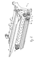
- a conditioner 11 is provided between the cross conveyors 8 and the mower 4, as him Figures 2 and 3 demonstrate.
- the conditioner 11 is advantageously combined with the respectively associated mower 4 to form an assembly, so that the conditioner can be pivoted together with the respective mower 4 upwards or independently of the transverse conveyor 8 can be pivoted upwards, for example, the mowed and Do not store conditioned crops in a swath, but scattered on the ground.
- the conditioner 11 comprises two superposed conditioning rollers 12 and 13, which form a pair of nip rolls and are driven in opposite directions, so that the crop is conveyed through between them.
- the two conditioning rollers 12 and 13 in this case have a deviating from the cylindrical shape surface geometry, 12 and 13 engage in each other when circulating the conditioning rollers.
- the conditioning rollers 12 and 13 have helical elevations or oblique ribs 14 which engage with each other when the two conditioning rollers 12 and 13 are driven in opposite directions (see. FIG. 3 ).
- the conditioner 11 comprises an additional deflection roller 15 which, like the two conditioning rollers 12 and 13 in the illustrated embodiment, extends over the entire width of the conditioner 11.
- the three rollers 12, 13 and 15 are advantageously arranged about mutually parallel axes.
- the guide roller 15 is arranged in the illustrated embodiment of its height approximately centrally between the two conditioning rollers 12 and 13 and spaced from them a piece.
- the guide roller 15 is at least approximately at its radius of the two conditioning rollers 12 and 13 spaced apart.
- the two conditioning rollers 12 and 13 are driven at the same rotational speed.
- the guide roller 15 is also driven, for which purpose the drive of the two conditioning rollers 12 and 13 is tapped.
- the guide roller 15 may be coupled via a chain drive 17 with the two conditioning rollers.
- the coupling may provide different rotational speeds of the guide roller 15 relative to the conditioning rollers.
- the coupling or the chain drive 17 may be dimensioned such that all three rollers 12, 13 and 15 rotate at the same rotational speed.
- the direction of rotation of the deflecting roller 15 is selected such that the upper side of the deflecting roller 15 moves away from the conditioning rollers 12 and 13.
- the lower conditioning roller 12 and the guide roller 15 preferably have the same direction of rotation.
- the guide roller 15 has a different from the two conditioning rollers 12 and 13 surface geometry.
- the guide roller 15 has in the longitudinal direction extending ribs 18, on the one hand cause better entrainment of the crop, but on the other hand also contribute to the further conditioning of the crop.
- a Abvantleitblech 19 which of course does not necessarily have to consist of a sheet of metal, but can also be formed by a skirt, a mat or a Stäbean angel.
- the Ab2011leitblech 19 advantageously extends inclined backwards / upwards to direct the discarded by the guide roller 15 crop obliquely backwards up.
- the Abmonyleitblech 19 protrudes to the rear a little way over the guide roller 15.
Landscapes
- Life Sciences & Earth Sciences (AREA)
- Environmental Sciences (AREA)
- Harvesting Machines For Specific Crops (AREA)
- Harvester Elements (AREA)
- Permanent Magnet Type Synchronous Machine (AREA)
- Threshing Machine Elements (AREA)
Claims (13)
- Machine de récolte comprenant au moins une faucheuse (4), un conditionneur (11) placé en aval de la faucheuse, un convoyeur transversal (8) placé en aval du conditionneur (11) pour la dépose de la marchandise récoltée et conditionnée dans un andain latéral, et un cylindre inverseur (15) pour la déviation et le transport de la marchandise récoltée et conditionnée sur le convoyeur transversal (8), caractérisé en ce que le conditionneur (11) présente une paire de cylindres de conditionnement (12, 13) tournant dans le sens contraire et disposés l'un au-dessus de l'autre, le cylindre inverseur (15) étant disposé à partir de sa hauteur entre les deux cylindres de conditionnement (12, 13) dans leur zone de distribution et pouvant être entraîné avec une vitesse, afin de jeter la marchandise récoltée sur le convoyeur transversal (8), une tôle chicane d'éjection (19) étant disposée au-dessus du cylindre inverseur (15).
- Machine de récolte selon l'une quelconque des revendications précédentes, le conditionneur (11) présentant une commande de cylindre (16) commune pour les deux cylindres de conditionnement (12, 13) et le cylindre inverseur (15) monté en aval.
- Machine de récolte selon l'une quelconque des revendications précédentes, les cylindres de conditionnement (12, 13) ou le cylindre inverseur (15) étant couplés les uns avec les autres au niveau de la transmission, de préférence au moyen d'une courroie d'entraînement ou d'une chaîne d'entraînement (17).
- Machine de récolte selon l'une quelconque des revendications précédentes, le cylindre inverseur (15) présentant une géométrie de surfaces différente des deux cylindres de conditionnement (12, 13).
- Machine de récolte selon l'une quelconque des revendications précédentes, le cylindre inverseur (15) présentant des nervures longitudinales (18) saillantes.
- Machine de récolte selon l'une quelconque des revendications précédentes, les deux cylindres de conditionnement (12, 13) formant des cylindres d'écrasement et/ou présentant des contours de surface s'engrenant les uns dans les autres.
- Machine de récolte selon l'une quelconque des revendications précédentes, les deux cylindres de conditionnement (12, 13) présentant des nervures longitudinales (14) agencées avec une forme hélicoïdale.
- Machine de récolte selon l'une quelconque des revendications précédentes, la tôle chicane d'éjection (19) étant disposée au-dessus du cylindre inverseur (15) de façon inclinée vers l'arrière/le haut.
- Machine de récolte selon l'une quelconque des revendications précédentes, le conditionneur (11) étant regroupé avec une faucheuse (4) pour former un ensemble qui est suspendu conjointement sur un cadre de machine (5).
- Machine de récolte selon l'une quelconque des revendications précédentes, plusieurs faucheuses (4) disposées dans différentes traces de roulement étant prévues avec respectivement un convoyeur transversal (8) monté en aval avec respectivement au moins un cylindre d'éjection (13).
- Machine de récolte selon l'une quelconque des revendications précédentes, la au moins une faucheuse (4) et/ou le au moins un convoyeur transversal (8) pouvant être amené(s) à partir d'une position de service abaissée dans une position de transport basculée vers le haut.
- Machine de récolte selon l'une quelconque des revendications précédentes, la au moins une faucheuse (4) et le au moins un convoyeur transversal (8) étant suspendus sur un cadre de machine commun de façon à pouvoir basculer respectivement autour d'un axe de pivotement allongé et dirigé dans le sens de marche.
- Machine de récolte selon l'une quelconque des revendications précédentes, celle-ci étant réalisée de façon à pouvoir être rapportée sur un tracteur.
Applications Claiming Priority (1)
| Application Number | Priority Date | Filing Date | Title |
|---|---|---|---|
| DE102005050157A DE102005050157A1 (de) | 2005-10-19 | 2005-10-19 | Erntemaschine |
Publications (2)
| Publication Number | Publication Date |
|---|---|
| EP1776859A1 EP1776859A1 (fr) | 2007-04-25 |
| EP1776859B1 true EP1776859B1 (fr) | 2008-06-11 |
Family
ID=37633613
Family Applications (1)
| Application Number | Title | Priority Date | Filing Date |
|---|---|---|---|
| EP06015617A Active EP1776859B1 (fr) | 2005-10-19 | 2006-07-26 | Machine de récolte |
Country Status (4)
| Country | Link |
|---|---|
| EP (1) | EP1776859B1 (fr) |
| AT (1) | ATE397854T1 (fr) |
| DE (2) | DE102005050157A1 (fr) |
| DK (1) | DK1776859T3 (fr) |
Cited By (1)
| Publication number | Priority date | Publication date | Assignee | Title |
|---|---|---|---|---|
| EP4011192A3 (fr) * | 2020-12-14 | 2022-08-31 | CLAAS Saulgau GmbH | Dispositif de récolte |
Families Citing this family (4)
| Publication number | Priority date | Publication date | Assignee | Title |
|---|---|---|---|---|
| CA2734475C (fr) | 2011-03-16 | 2012-10-09 | Macdon Industries Ltd. | Rouleau d'entrainement de convoyeur a toile d'une tete de moissonneuse-batteuse |
| DE202012012883U1 (de) | 2012-01-10 | 2014-02-10 | Alois Pöttinger Maschinenfabrik Ges.m.b.H. | Mähmaschine |
| DE202012002112U1 (de) | 2012-02-29 | 2013-06-04 | Alois Pöttinger Maschinenfabrik Gmbh | Erntemaschine |
| DE202019102625U1 (de) * | 2019-05-10 | 2020-08-11 | Pöttinger Landtechnik Gmbh | Erntemaschine |
Family Cites Families (4)
| Publication number | Priority date | Publication date | Assignee | Title |
|---|---|---|---|---|
| CA2136499C (fr) * | 1994-11-23 | 2003-04-15 | Francois Talbot | Rouleau de conditionnement pour conditionneur de fourrage |
| FR2823636A1 (fr) * | 2001-04-18 | 2002-10-25 | Kuhn Sa | Machine de fenaison, notamment une faucheuse avec un dispositif groupeur d'andains |
| FR2837347B1 (fr) * | 2002-03-21 | 2004-07-30 | Kuhn Sa | Faucheuse agricole comportant un vehicule porteur et plusieurs unites de travail |
| US6955034B1 (en) * | 2004-07-24 | 2005-10-18 | Cnh America Llc | Crop Conditioner frame with interchangeable rollers |
-
2005
- 2005-10-19 DE DE102005050157A patent/DE102005050157A1/de not_active Withdrawn
-
2006
- 2006-07-26 EP EP06015617A patent/EP1776859B1/fr active Active
- 2006-07-26 AT AT06015617T patent/ATE397854T1/de active
- 2006-07-26 DK DK06015617T patent/DK1776859T3/da active
- 2006-07-26 DE DE502006000899T patent/DE502006000899D1/de active Active
Cited By (1)
| Publication number | Priority date | Publication date | Assignee | Title |
|---|---|---|---|---|
| EP4011192A3 (fr) * | 2020-12-14 | 2022-08-31 | CLAAS Saulgau GmbH | Dispositif de récolte |
Also Published As
| Publication number | Publication date |
|---|---|
| DE102005050157A1 (de) | 2007-05-31 |
| DE502006000899D1 (de) | 2008-07-24 |
| EP1776859A1 (fr) | 2007-04-25 |
| DK1776859T3 (da) | 2008-10-27 |
| ATE397854T1 (de) | 2008-07-15 |
Similar Documents
| Publication | Publication Date | Title |
|---|---|---|
| AT389973B (de) | Maschine zum ernten von mais od. dgl. stengelartigem erntegut | |
| EP0173223B1 (fr) | Moissoneuse-batteuse avec un dispositif de séparation fonctionnant d'après le système de flux axial | |
| EP1417877B1 (fr) | Rouleau de cueillette | |
| DE102006043314B4 (de) | Erntemaschine | |
| DE19931684C1 (de) | Gerätekombination zum Ernten von landwirtschaftlichem Halmgut | |
| DE102010010862B4 (de) | Heuwerbungsmaschine | |
| DE10153198A1 (de) | Einzugs- und Pflückeinrichtung | |
| DE19959338A1 (de) | Einzugs- und Pflückeinrichtung sowie Erntemaschine | |
| EP0891693B1 (fr) | Barre de coupe à disque et dispositif de coupe | |
| EP1776859B1 (fr) | Machine de récolte | |
| DE10257776A1 (de) | Einzugs- und Pflückeinrichtung | |
| EP0917819B1 (fr) | Moissonneuse-batteuse équipée d'un hache-paille | |
| DE2705236C2 (de) | Landwirtschaftliche Maschine mit einem Mähwerk | |
| DE2653463A1 (de) | Konditioniereinrichtung fuer landwirtschaftliches erntegut | |
| DE2303528C3 (de) | Maishäcksler | |
| AT390164B (de) | Vorrichtung zum aufnehmen von sich auf dem boden befindlichen futter | |
| DE2160818C2 (de) | Kreiselheuwerbungsmaschine | |
| DE1297390B (de) | Dresch- und Trennvorrichtung fuer im Querlaengsfluss arbeitende Maehdrescher | |
| DE2837624A1 (de) | Schneidwerk fuer selbstfahrende landmaschinen zur breitablage | |
| DE69423980T2 (de) | Apparat zum fördern von spreu, abfallgetreide, kleinkörnern usw. in einer erntemaschine | |
| DE1800498C3 (de) | Aufsammelpresse | |
| DE3541976A1 (de) | Aufbereiterwalze | |
| DE102008021784A1 (de) | Erntemaschine mit Schrägförderer | |
| DE3033299C2 (de) | Antrieb für eine Schneidvorrichtung | |
| DE3923637C2 (fr) |
Legal Events
| Date | Code | Title | Description |
|---|---|---|---|
| PUAI | Public reference made under article 153(3) epc to a published international application that has entered the european phase |
Free format text: ORIGINAL CODE: 0009012 |
|
| AK | Designated contracting states |
Kind code of ref document: A1 Designated state(s): AT BE BG CH CY CZ DE DK EE ES FI FR GB GR HU IE IS IT LI LT LU LV MC NL PL PT RO SE SI SK TR |
|
| AX | Request for extension of the european patent |
Extension state: AL BA HR MK YU |
|
| 17P | Request for examination filed |
Effective date: 20070427 |
|
| 17Q | First examination report despatched |
Effective date: 20070605 |
|
| AKX | Designation fees paid |
Designated state(s): AT DE DK FR IT |
|
| GRAP | Despatch of communication of intention to grant a patent |
Free format text: ORIGINAL CODE: EPIDOSNIGR1 |
|
| GRAS | Grant fee paid |
Free format text: ORIGINAL CODE: EPIDOSNIGR3 |
|
| GRAA | (expected) grant |
Free format text: ORIGINAL CODE: 0009210 |
|
| AK | Designated contracting states |
Kind code of ref document: B1 Designated state(s): AT DE DK FR IT |
|
| REF | Corresponds to: |
Ref document number: 502006000899 Country of ref document: DE Date of ref document: 20080724 Kind code of ref document: P |
|
| PLBE | No opposition filed within time limit |
Free format text: ORIGINAL CODE: 0009261 |
|
| STAA | Information on the status of an ep patent application or granted ep patent |
Free format text: STATUS: NO OPPOSITION FILED WITHIN TIME LIMIT |
|
| 26N | No opposition filed |
Effective date: 20090312 |
|
| REG | Reference to a national code |
Ref country code: FR Ref legal event code: PLFP Year of fee payment: 11 |
|
| REG | Reference to a national code |
Ref country code: FR Ref legal event code: PLFP Year of fee payment: 12 |
|
| REG | Reference to a national code |
Ref country code: FR Ref legal event code: PLFP Year of fee payment: 13 |
|
| PGFP | Annual fee paid to national office [announced via postgrant information from national office to epo] |
Ref country code: AT Payment date: 20190618 Year of fee payment: 14 |
|
| REG | Reference to a national code |
Ref country code: AT Ref legal event code: MM01 Ref document number: 397854 Country of ref document: AT Kind code of ref document: T Effective date: 20200726 |
|
| PG25 | Lapsed in a contracting state [announced via postgrant information from national office to epo] |
Ref country code: AT Free format text: LAPSE BECAUSE OF NON-PAYMENT OF DUE FEES Effective date: 20200726 |
|
| P01 | Opt-out of the competence of the unified patent court (upc) registered |
Effective date: 20230613 |
|
| PGFP | Annual fee paid to national office [announced via postgrant information from national office to epo] |
Ref country code: IT Payment date: 20230609 Year of fee payment: 18 |
|
| PGFP | Annual fee paid to national office [announced via postgrant information from national office to epo] |
Ref country code: FR Payment date: 20230726 Year of fee payment: 18 Ref country code: DK Payment date: 20230713 Year of fee payment: 18 Ref country code: DE Payment date: 20230613 Year of fee payment: 18 |