EP1776022B1 - Protective helmet - Google Patents
Protective helmet Download PDFInfo
- Publication number
- EP1776022B1 EP1776022B1 EP05767938A EP05767938A EP1776022B1 EP 1776022 B1 EP1776022 B1 EP 1776022B1 EP 05767938 A EP05767938 A EP 05767938A EP 05767938 A EP05767938 A EP 05767938A EP 1776022 B1 EP1776022 B1 EP 1776022B1
- Authority
- EP
- European Patent Office
- Prior art keywords
- helmet
- anisotropic
- layer
- head
- helmet according
- Prior art date
- Legal status (The legal status is an assumption and is not a legal conclusion. Google has not performed a legal analysis and makes no representation as to the accuracy of the status listed.)
- Expired - Lifetime
Links
Images


Classifications
-
- A—HUMAN NECESSITIES
- A42—HEADWEAR
- A42B—HATS; HEAD COVERINGS
- A42B3/00—Helmets; Helmet covers ; Other protective head coverings
- A42B3/04—Parts, details or accessories of helmets
- A42B3/06—Impact-absorbing shells, e.g. of crash helmets
- A42B3/062—Impact-absorbing shells, e.g. of crash helmets with reinforcing means
- A42B3/063—Impact-absorbing shells, e.g. of crash helmets with reinforcing means using layered structures
- A42B3/064—Impact-absorbing shells, e.g. of crash helmets with reinforcing means using layered structures with relative movement between layers
-
- A—HUMAN NECESSITIES
- A42—HEADWEAR
- A42B—HATS; HEAD COVERINGS
- A42B3/00—Helmets; Helmet covers ; Other protective head coverings
- A42B3/04—Parts, details or accessories of helmets
- A42B3/10—Linings
- A42B3/12—Cushioning devices
- A42B3/124—Cushioning devices with at least one corrugated or ribbed layer
-
- A—HUMAN NECESSITIES
- A42—HEADWEAR
- A42B—HATS; HEAD COVERINGS
- A42B3/00—Helmets; Helmet covers ; Other protective head coverings
- A42B3/04—Parts, details or accessories of helmets
- A42B3/10—Linings
- A42B3/12—Cushioning devices
- A42B3/125—Cushioning devices with a padded structure, e.g. foam
- A42B3/128—Cushioning devices with a padded structure, e.g. foam with zones of different density
Definitions
- the present invention relates to a protective helmet, such as a helmet which can be worn by a cyclist, motorcyclist, pilot, bobsleigh sportsperson, etc. to protect against injury.
- a protective helmet such as a helmet which can be worn by a cyclist, motorcyclist, pilot, bobsleigh sportsperson, etc. to protect against injury.
- These helmets generally consist of three functional units, which are conceived in three separate layers that are always ordered as follows: a hard outer shell that distributes forces acting on the head over a larger surface, an energy-absorbing middle shell, and an inner layer that guarantees a comfortable fit on the head.
- US 2002/0023291 A1 describes a helmet designed to protect the head and brain from both linear and rotational impact energy, constructed of 4 layers, the layers comprising polyurethane, monoprene gel, polyethylene and either polycarbonate or polypropoylene.
- US 6,658,671 describes a protective helmet with an inner and an outer shell with in between a sliding layer and whereby the inner and the outer shell are interconnected with connecting members.
- EP1142495 A1 describes a helmet in which a layer of elastic body (which may be a gel) is provided between the inner side of the shell and the shock absorbing liner, or in between two layers of the shock absorbing liner.
- WO2004/032659A1 describes a head protective device with an inner and an outer layer, and an interface layer with a spherical curvature, allowing displacement of the outer layer with respect to the inner layer.
- the interface layer may consist of a viscous medium, a hyper-elastic structure, an elastomer-based lamellar structure, or connecting members.
- These helmets only allow a limited rotational displacement of the inner shell with respect to the outer shell, because the shape of the helmet is not a perfect hemisphere. Consequently, the energy that can be dissipated is limited as well. Furthermore, these helmets have poor ventilation capacities, and are relatively complex to manufacture.
- a further protective helmet is known from US-A-3 447 163 .
- the present invention seeks to provide a helmet which offers better protection against head (brain, skull, etc) injury and damage as a consequence of linear as well as rotational acceleration upon an accident.
- a first aspect of the present invention provides a protective helmet according to independent claim 1.
- a cellular material is one made up of an interconnected network of struts and/or plates which form edges and faces or walls of cells.
- Cellular materials with cells having cell walls can provide the advantage that crushing or compaction of the walls can absorb more impact energy than materials with only pillars or struts.
- the use of a layer which is formed of an anisotropic material has the benefit of allowing rotational energy, i.e. energy which is applied to the helmet by tangentially-directed forces with respect to the surface of the helmet and hence with respect to the head of the wearer, to be absorbed by the helmet in such a way that the rotational acceleration or deceleration of the head is kept low.
- the energy absorption is achieved without the need for layers to slide with respect to one another, and thus the helmet does not need to be perfectly spherical.
- This provides a protective helmet that reduces the risk of injury for the wearer, by protecting against different types of injury.
- the anisotropic material can be a macroscopic or microscopic cellular, foam, preferably closed-cell.
- a closed cell structure can have some open cells, e.g. when some cell walls rupture. However, the closed cell structure does have mainly cells with cell walls whereas an open cell structure comprises mainly struts and no cell walls.
- anisotropic materials can provide good energy absorption in both tangential and normal directions with respect to the helmet and thus it is possible to provide a layer with both properties in a compact structure.
- a material is polyethersulfone (PES) although other plastic materials, e.g. thermoplastic, thermosetting or elastomeric materials may be used, e.g. polyurethane or other materials, e.g. foamed metals or carbon.
- the helmet preferably combines five functional units to protect the head against both linear and rotational accelerations which protect the head against both skull and brain damage.
- the first functional unit of the helmet is a hard layer that distributes forces acting on the head over a larger surface; the second unit is a relatively soft layer that is able to absorb a part of the impact energy without transferring potentially harmful forces to the head; the third functional unit protects the head against normal forces (F n on Figure 1 ); the fourth unit protects the head against tangential forces (F t on Figure 1 ).
- the fifth functional unit ensures a comfortable fit of the helmet on the head.
- these functional units are embodied as physical layers, and a single functional unit does not necessarily correspond to a single physical layer (i.e.
- the third (3) and fourth (4) functional units are combined into one layer of anisotropic material.
- Two functional units can be designed into two physical layers where each of the layers takes part in both functions; for example, two layers with different "easy" directions of the anisotropy, i.e. directions in which there is a low resistance to deformation compared to other directions, protect against linear and/or rotational accelerations generated by forces in two different directions.
- an extra protection for other parts of the head may be provided, e.g. chin protection or protection for the temples or eyes, and combined in the protective helmet of the present invention.
- An embodiment of the protective helmet will be described which combines up to five functional units to protect the head against both linear and rotational accelerations.
- this helmet When compared to standard helmets, which only consist of a hard outer shell (1), an energy-absorbing middle shell (3), and an inner fitting layer (5), this helmet offers a more complete protection by absorbing a part of the impact energy in a dedicated functional unit (2) without transferring potentially harmful forces to the head (and inner physical layers, if present), and by a protection against tangential impact forces in a dedicated functional unit (4). All functional units are able to act simultaneously.
- the three functional units of a standard helmet are always materialized into the same three physical layers, which are always ordered the same way, while in case of a protective helmet according to the invention, the five functional units are materialized into a number physical layers, wherein one single functional unit does not necessarily correspond to one single physical layer (i.e. several functional units can be combined into one physical layer and one functional unit can be designed into several physical layers).
- a protective helmet (6) - according to the invention shown in Figure 4 - comprises up to five functional units.
- a unit is not necessarily a layer.
- the first functional unit (1) is a hard layer that distributes forces acting on the head over a larger surface;
- the second unit (2) is a relatively soft layer that is able to absorb a part of the impact energy without transferring potentially harmful forces to the head;
- the third functional unit (3) protects the head against normal forces (F n );
- the fourth unit (4) protects the head against tangential forces (F t ).
- the fifth functional unit (5) ensures a comfortable fit of the helmet on the head.
- An embodiment of a protective helmet may comprise an arrangement of five different physical layers, where each layer corresponds to one functional unit.
- the first layer (a) is a hard outer shell that distributes forces over a larger surface;
- the second layer (b) consists of a soft material that is able to absorb a part of the impact energy without transferring potentially harmful forces to the head and to the inner layers;
- the third layer (c) protects the head against normal forces;
- the fourth layer (d) protects the head against tangential forces.
- the fifth physical layer (e) which is intended for contact with the head of the wearer, ensures a comfortable fit.
- the first functional unit (1) distributes forces acting on the head over a larger surface, and protects against the penetration of objects.
- this functional unit (1) corresponds to one outer physical layer (a) - this layer is relatively thin and can be made out of polycarbonate or fibre-reinforced plastics or a metal such as aluminium, for example.
- the outer physical layer of the helmet can be relatively thin, such as between 0 mm and 2 mm.
- the second functional unit (2) is able to absorb a part of the impact energy without transferring potentially harmful forces to the head.
- the physical layer (b) corresponding to the functional unit (2) is relatively thicker and softer when compared to the outer layer (a).
- the physical layer can be made out of, for example, polyurethane foam or polystyrene, and the construction can vary in different ways, which are explained further.
- the core material (i.e. the energy-absorbing middle shell) of a protection helmet consists of foam, which behaves under compression load as shown on Figure 6 : initially the elastic deformation of the material is linear, then there is a non-linear plateau where the material is compacted, and finally deformation of the compact material occurs [8]. Standardized compression tests can be used to characterize these foam parameters. When comparing different foams (e.g. polystyrene foams A and B where A has a higher density when compared to B, see Figure 6 ), the elastic and plastic areas are different. The energy that is absorbed can be calculated as the integral of the stress-strain curve, and is represented (for elastic compression of material B) by the hatched area on Figure 6 . For materials that are traditionally used as liner material, the plateau lies close to the stress at which damage to the skull and brain are occurring [7].
- foams e.g. polystyrene foams A and B where A has a higher density when compared to B, see Figure 6
- a functional unit (2) is conceived to absorb a part of the impact energy without transferring potentially harmful forces to the head (i.e. forces lower than a maximum value of 50 kN).
- the physical layer (b) corresponding to functional unit (2) is relatively soft (see material C on Figure 7 ) when compared to materials that are traditionally used as liner material (such as material B described above, see Figure 7 ).
- the force transferred by the material C while effective i.e. while it is able to absorb energy, see material C on Figure 7
- the energy which can be absorbed is the integral of the force times the distance moved - the lower the force, the more distance must be used to absorb a certain amount of energy.
- the present invention can use softer and thicker materials than used in known devices.
- the construction of the functional unit (2) may vary in different ways, e.g. air, foam, honeycomb patterns, and the unit may be combined with other units into one physical layer. Furthermore the physical layer or part of a physical layer corresponding to the functional unit (2) may absorb energy by elastic and/or plastic deformation.
- the second functional unit (2) is preferably materialized into a physical layer that is thicker than the outer layer, such as between 2 mm and 50 mm, and is made of a softer material than the outer layer, such as polyurethane or polystyrene.
- the third functional unit (3) is able to protect the head against normal forces, inter alia, by limiting the deformation of the skull.
- the third functional unit is able to absorb energy arising from linear impact to protect the head from skull damage. This function is comparable to the helmets that are currently available on the market.
- this layer may be made out of polyurethane foam or polystyrene, for example.
- the third functional unit (3) can be materialized into a physical layer (c) that is made from polyurethane or polystyrene, which is softer than the outer layer (a), but firmer than the second physical layer (b).
- the physical layer or part of a physical layer corresponding to the functional unit (3) may absorb energy by elastic and/or plastic deformation.
- the fourth functional unit (4) is able to protect the head against forces which would induce rotational damage to the brain, i.e. it reduces rotational deceleration or acceleration forces on the head and/or absorbs energy arising from an impact on the helmet having a rotational effect on the head.
- this layer has a relatively low resistance against deformation caused by a force in a tangential direction. This can be realised by using anisotropic materials and/or material structures. Anisotropy is defined as a variation of one or more material and/or structural properties with direction. Since most materials are anisotropic to some extent (e.g.
- a material and/or structure is defined as anisotropic when the variation of a property of the material and/or structure with direction exceeds a threshold value, which depends on the material characterization test used.
- a standardized compression test i.e. a standardised procedure such as disclosed in a national or international standard
- a material/structure sample is subjected to compression in three orthogonal directions, and the plateau-stress (which is the mean level of the stress in the compacting zone, see Figure 6 ) is calculated for each direction. Examples of such tests are ASTM-C-365: Standard test Method for flatwise compressive properties of sandwich cores and ASTM D-1621: Standard test method for compressive properties of rigid cellular plastics.
- a material or structure is defined as anisotropic when the difference in plateau-stress between two orthogonal directions exceeds 15%.
- a higher level of anisotropy is preferred. The reason is that the direction of "easy" deformation (directions in which the material has a low resistance to deformation compared to other directions) is arranged to be along a direction of tangential impact so that the maximum acceleration or deceleration of the head is reduced.
- a preferred material and/or structure in accordance with the present invention is defined as a degree of anisotropy characterised by the ratio of the plateau-stress at 0° testing to the plateau-stress at 75° testing exceeding the value 5.
- This degree of anisotropy provides a material which can withstand radial forces to the head while allowing movement of the helmet rotationally relative to the head at low forces, thus providing a low acceleration to the head while still absorbing the energy of the blow.
- isotropic polystyrene (PS) has a ratio of 2,8 (0,73/0,26) while anisotropic polyethersulfone (PES) has a ratio of 14,3 (0,43/0,03).
- an anisotropic cellular material such as a foam (see Figure 8 left), where the material properties in different directions are different and depend, inter alia, on the cell orientation and cell wall thickness in different directions.
- a cellular material is one made up of an interconnected network of struts and/or plates which form edges and faces or walls of cells.
- a closed cell foam generally has cell walls enclosing and closing each cell to thereby trap a fluid such as a gas or a liquid but even a closed cell foam may have some open cells, e.g. where a cell wall ruptures.
- An open cell structure has mainly struts forming the cells with few or no cell walls.
- a closed cell structure is particularly preferred in accordance with the present invention as such materials can be made anisotropic so that they collapse readily in one direction, preferably a direction which is tangential to the helmet while still absorbing approximately the same amount of rotational energy as an isotropic foam.
- the anisotropic properties may be determined by the fabrication methodology of the foam. Suitable methods are described, for example, in " Polyurethane Handbook", ed. G. Oertle, Hanser Verlag, 1994, in particular "Relationships between production methods and properties", page 277ff ; or " Engineering Materials Handbook", vol. 2, Engineered Plastics, ASM Int. 1988, pages 256-264 : Polyurethanes (H. F. Hespe) and pages 508-513: Properties of thermoplastic structural foams, (G. W. Brewer ).
- Examples are (i) by blowing a fluid such as steam in specific directions into a mould during foaming which results in an anisotropic foam structure, (ii) pulling and extending the foam in one direction during foaming to elongate the cells, (iii) allowing slow foaming so that the natural tendency of gas bubbles formed during this process to move upwards against gravity is used to elongate the cells, (iv) enhancing the effect of gravity by applying a pressure differential; e.g. vacuum, to draw the forming gas bubbles in one direction etc.
- a pressure differential e.g. vacuum
- Honeycomb structures can be fabricated with any desired ratio between cell height and width to thereby influence the anisotropic properties.
- a honeycomb structure can be made in sheet formed and then formed into the shape of a helmet or onto the helmet, e.g. by applying heat.
- the honeycomb structure can be mechanically fixed to other layers of the helmet by any suitable means, e.g. adhesive or glue, staples, heat sealing.
- suitable means e.g. adhesive or glue, staples, heat sealing.
- a physical layer is thereby provided consisting of an anisotropic structure that has a low resistance against deformation induced by tangential impacts on the helmet, which results in the structural behaviour under influence of a tangential force F t , as illustrated on Figure 9 for both an anisotropic foam structure (left) and an anisotropic honeycomb structure (right).
- the stress plateau of an anisotropic material (material B on Figure 10 ) is much lower than the stress plateau of an isotropic material (material A on Figure 10 ), in the case where a tangential force is applied to the material and in the appropriate directions for the "easy" direction of the anisotropic material. Consequently, the level of the force that is transferred to the head within the helmet will be lower, which will result in lower rotational accelerations.
- the energy that is dissipated during this deformation (hatched area under curve B on Figure 10 ) is nevertheless comparable to the energy that is dissipated by an isotropic material (hatched area under curve A on Figure 10 ), due to the fact that these anisotropic structures allow a high degree of deformation in the tangential direction.
- the construction of the functional unit (4) may vary in different ways, e.g. air, foam, honeycomb patterns, rubber.
- anisotropic materials or materials that can be produced with anisotropic material properties suitable for use in the helmet e.g. as cellular material such as foams or honeycombs, only the anisotropic form materials forming part of the present invention:
- anisotropic materials such as polyethersulfone (PES) show the same behaviour as an isotropic material, in case a normal force is applied to the material. Consequently, a physical layer consisting of an anisotropic structure can also take the role of functional unit (3).
- the functional unit (4) may therefore be combined with other units into one physical layer, e.g. combining unit (3) and (4) into one layer that absorbs energy arising from both normal (linear) and tangential (rotational) impact.
- an anisotropic material polyethersulfone (PES)
- PS polystyrene
- PU 1 isotropic polyurethane
- a shear testing kit consisting of different spacers and fixed plates (see Figure 11 ) was conceived to allow the following testing angles ⁇ : 0°, 15°, 45°, 75° and 90°.
- the specimens were attached to the shear kit by using cyanoacrylate glue (Loctite 406 nr. 40637) on both sides of the specimens, in order to avoid slippage of the specimens.
- cyanoacrylate glue Loctite 406 nr. 40637
- FIG. 13 shows a schematic overview of this setting.
- a polyester ball weight 7 kg, radius 11 cm
- the test monsters were attached to the fixed plate by using double-sided tape (brand Tesa, width 50mm, carpet fixation, product code 110002).
- Two uniaxial accelerometers (1 and 2 in table 1) are used to measure the linear acceleration in the direction of the arrow (see Figure 13 ). From these accelerations, the rotational acceleration of the pendulum is calculated.
- anisotropic materials such as polyethersulfone (PES) and anisotropic polyurethane (PU A )
- PES polyethersulfone
- PU A anisotropic polyurethane
- Table 1 illustrates that anisotropic materials successfully reduce the rotational accelerations, which are significantly lower for PES when compared to PS (about 40% lower). Differences in calculated values for the two accelerometers (1 and 2 in table 1) are due to calibration factors.
- Rotational acceleration (rad/s 2 ) 356.4 364.0 297.2 310.4 516.2 455.8 St.Dev rotational acceleration (rad/s 2 ) 17.5 17.6 30.7 19.9 118.6 80.2 Rotational acceleration (% less compared to reference (PS)) 31.0 29.5 42.4 39.9 - - Measured absorbed energy Joules (determined from video recording of the experiment) 66 62 64 Input energy Joules 69.1 69.1 69.1 %age absorption 95.7 89.8 92.5
- the degree and the orientation of the anisotropy can be adjusted (see anisotropic layer (a) on Figure 14 ) to optimize the proportion of the protection against normal impact forces with respect to the protection against tangential impact forces, in order to protect against specific types of impact, if necessary.
- a combination can be made of several physical layers with different degrees of and orientations of anisotropy, as illustrated in Figure 14 . In this case both physical layer (a) and physical layer (b) contribute to the protection against normal impact forces (functional unit 3) and against tangential impact forces of different directions (functional unit 4).
- the physical layer (e) corresponding the fifth functional unit (5) is intended for contact with the head of the wearer, and ensures a comfortable fit.
- this layer ensures not only comfort, but also a custom-made fit, which is important to decrease the risk that the helmet would separate from the head during impact.
- This custom-made fit is obtained by incorporating the anthropometrical characteristics of the head in the design of the layer, e.g. by copying the dimensions of the head exactly onto the layer, or by using separate modules that can be adjusted with respect to each other.
Landscapes
- Helmets And Other Head Coverings (AREA)
- Gyroscopes (AREA)
Abstract
Description
- The present invention relates to a protective helmet, such as a helmet which can be worn by a cyclist, motorcyclist, pilot, bobsleigh sportsperson, etc. to protect against injury.
- Epidemiological studies on accidents (e.g. bicycle accidents) show that a substantial number of the subjects who call for medical aid, are suffering from skull and brain damage. Furthermore, cranio-cerebral traumas are a direct cause for the majority of the fatal accidents. A protection helmet should therefore protect the head against these traumas.
- There are many types of protective helmets on the market, with different designs and characteristics. They are designed to satisfy legal requirements, but do generally not offer a protection to the most common skull and brain damages. At present, these legal requirements are related to the maximum linear acceleration that may occur in the centre of gravity of the brain at a specified load, and may involve tests in which a so-called "dummy skull", equipped with a helmet, is subjected to impact. As a result of these legal requirements, helmets that are currently available on the market offer a good protection in the case of a normal impact on the head. Fractures of the skull and/or pressure or abrasion injuries of the brain tissue typically occur after this type of impact. These helmets generally consist of three functional units, which are conceived in three separate layers that are always ordered as follows: a hard outer shell that distributes forces acting on the head over a larger surface, an energy-absorbing middle shell, and an inner layer that guarantees a comfortable fit on the head.
- However, mathematical simulations (see
Figure 1 ) show that rotational accelerations of the head increase with an increasing tangential component Ft of the impact force F (seeFigure 3 ), while helmets that are currently available on the market do not offer a sufficient protection against impact that is tangential to the head. Furthermore, literature (both early and recent [1]-[7]) shows that the most common brain injuries are related to rotational accelerations (not linear accelerations) while legal requirements and standards do not include this aspect. Typical injuries related to head rotation are contusions, ASDH (Acute Sub-Dural Haematoma; bleeding as a consequence of blood vessels rupturing), and DAI (Diffuse Axonal Injuries; widespread damage to axons in the white matter of the brain). Although the understanding of the precise mechanical processes that lead to these specific injuries is still imperfect, recent research [7] has revealed, inter alia, a relation between brain parenchyma and bridging vein lesions on the one hand and the rotational acceleration of the head on the other hand. The type and the severity of the injury depend on the development of impact parameters as a function of time, such as the duration and the amplitude. -
US 2002/0023291 A1 describes a helmet designed to protect the head and brain from both linear and rotational impact energy, constructed of 4 layers, the layers comprising polyurethane, monoprene gel, polyethylene and either polycarbonate or polypropoylene.US 6,658,671 describes a protective helmet with an inner and an outer shell with in between a sliding layer and whereby the inner and the outer shell are interconnected with connecting members.EP1142495 A1 describes a helmet in which a layer of elastic body (which may be a gel) is provided between the inner side of the shell and the shock absorbing liner, or in between two layers of the shock absorbing liner.WO2004/032659A1 describes a head protective device with an inner and an outer layer, and an interface layer with a spherical curvature, allowing displacement of the outer layer with respect to the inner layer. The interface layer may consist of a viscous medium, a hyper-elastic structure, an elastomer-based lamellar structure, or connecting members. These helmets, however, only allow a limited rotational displacement of the inner shell with respect to the outer shell, because the shape of the helmet is not a perfect hemisphere. Consequently, the energy that can be dissipated is limited as well. Furthermore, these helmets have poor ventilation capacities, and are relatively complex to manufacture. A further protective helmet is known fromUS-A-3 447 163 . - The present invention seeks to provide a helmet which offers better protection against head (brain, skull, etc) injury and damage as a consequence of linear as well as rotational acceleration upon an accident.
- A first aspect of the present invention provides a protective helmet according to
independent claim 1. - A cellular material is one made up of an interconnected network of struts and/or plates which form edges and faces or walls of cells. Cellular materials with cells having cell walls can provide the advantage that crushing or compaction of the walls can absorb more impact energy than materials with only pillars or struts. The use of a layer which is formed of an anisotropic material has the benefit of allowing rotational energy, i.e. energy which is applied to the helmet by tangentially-directed forces with respect to the surface of the helmet and hence with respect to the head of the wearer, to be absorbed by the helmet in such a way that the rotational acceleration or deceleration of the head is kept low. The energy absorption is achieved without the need for layers to slide with respect to one another, and thus the helmet does not need to be perfectly spherical. This provides a protective helmet that reduces the risk of injury for the wearer, by protecting against different types of injury. The anisotropic material can be a macroscopic or microscopic cellular, foam, preferably closed-cell. A closed cell structure can have some open cells, e.g. when some cell walls rupture. However, the closed cell structure does have mainly cells with cell walls whereas an open cell structure comprises mainly struts and no cell walls.
- It has been found that some anisotropic materials can provide good energy absorption in both tangential and normal directions with respect to the helmet and thus it is possible to provide a layer with both properties in a compact structure. One example of such a material is polyethersulfone (PES) although other plastic materials, e.g. thermoplastic, thermosetting or elastomeric materials may be used, e.g. polyurethane or other materials, e.g. foamed metals or carbon.
- The helmet preferably combines five functional units to protect the head against both linear and rotational accelerations which protect the head against both skull and brain damage. The first functional unit of the helmet is a hard layer that distributes forces acting on the head over a larger surface; the second unit is a relatively soft layer that is able to absorb a part of the impact energy without transferring potentially harmful forces to the head; the third functional unit protects the head against normal forces (Fn on
Figure 1 ); the fourth unit protects the head against tangential forces (Ft onFigure 1 ). The fifth functional unit ensures a comfortable fit of the helmet on the head. There are various ways in which these functional units are embodied as physical layers, and a single functional unit does not necessarily correspond to a single physical layer (i.e. several functional units can be combined into one physical layer and one functional unit can be designed into several physical layers). The layers can be kept together, for example, by glue. All combinations/sequences of physical layers are possible. In one preferred embodiment the third (3) and fourth (4) functional units are combined into one layer of anisotropic material. - Two functional units can be designed into two physical layers where each of the layers takes part in both functions; for example, two layers with different "easy" directions of the anisotropy, i.e. directions in which there is a low resistance to deformation compared to other directions, protect against linear and/or rotational accelerations generated by forces in two different directions.
- In another aspect of the invention, also an extra protection for other parts of the head may be provided, e.g. chin protection or protection for the temples or eyes, and combined in the protective helmet of the present invention.
- Embodiments of the present invention will be described, by way of example, with reference to the accompanying drawings in which:
-
Figure 1 shows a graphic representation of an external force F acting on the head at an angle α. This force F can be subdivided into a tangential component Ft and a normal component Fn; -
Figure 2 shows the linear acceleration of the head (left) and the rotational acceleration of the head (right) as a function of time after impact by an external force F under an angle α=0°, and the corresponding linear and rotational peak accelerations P1 and Pr; -
Figure 3 gives the linear (left) and rotational (right) peak acceleration of the head after impact by an external force F as a function of the impact angle α, as defined onFigure 1 ; -
Figure 4 shows a cross-section of functional units of a protective helmet according to the invention; -
Figure 5 shows a cross-section of a possible arrangement of physical layers of a protective helmet according to the functional units ofFigure 4 ; -
Figure 6 shows the stress-strain behaviour of two different foam materials (A and B) under compression load; the hatched area represents the energy that is absorbed during both elastic deformation and compaction or crushing, i.e. plastic deformation; -
Figure 7 shows the combined stress-strain behaviour of two different materials (B and C) under compression load; the hatched area represents the energy that is absorbed during both elastic deformation and compaction or crushing, i.e. plastic deformation. In zone C, mainly material C is working, while in zone B, mainly material B is working; -
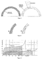
Figure 8 shows a cross-section of a physical layer that consists of an anisotropic cell structure (left) and a physical layer not forming part of the present invention that consists of an anisotropic honeycomb structure (right); -
Figure 9 shows a cross-section of a physical layer that consists of an anisotropic cell structure (left), and a physical layer not forming part of the present invention that consists of an anisotropic honeycomb structure (right) behaving anisotropically under influence of a tangential force component Ft; -
Figure 10 compares material behaviour under influence of a tangential force (stress as a function of strain) of an isotropic structure (material A) with an anisotropic structure (material B), N.B. Under normal forces the behaviour of the two materials would be similar ; -
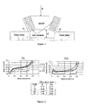
Figure 11 illustrates the measurement setup where 2 test sample blocks (separated by a spacer) are subjected to an external force F, which is acting on the test samples at an angle β. Force F and displacement d are captured as a function of time; -
Figure 12 compares material behaviour (stress as a function of strain) of PS (polystyrene, left) and PES (polyethersulfone, right) for different test angles β; -
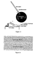
Figure 13 illustrates the measurement setup where a test sample block is subjected to an external force F which is exerted by a ball on a pendulum, and which is acting on the test sample at an angle β; and, -
Figure 14 illustrates how the orientation of the anisotropy can be varied, and how layers with a different orientation and/or degree of anisotropy can be combined. - The present invention will be described with respect to particular embodiments and with reference to certain drawings but the invention is not limited thereto but only by the claims. Any reference signs in the claims shall not be construed as limiting the scope. The drawings described are only schematic and are non-limiting. In the drawings, the size of some of the elements may be exaggerated and not drawn on scale for illustrative purposes. Where the term "comprising" is used in the present description and claims, it does not exclude other elements or steps. Where an indefinite or definite article is used when referring to a singular noun e.g. "a" or "an", "the", this includes a plural of that noun unless something else is specifically stated.
- Furthermore, the terms first, second, third and the like in the description and in the claims, are used for distinguishing between similar elements and not necessarily for describing a sequential or chronological order. It is to be understood that the terms so used are interchangeable under appropriate circumstances and that the embodiments of the invention described herein are capable of operation in other sequences than described or illustrated herein.
- Moreover, the terms top, bottom, over, under and the like in the description and the claims are used for descriptive purposes and not necessarily for describing relative positions. It is to be understood that the terms so used are interchangeable under appropriate circumstances and that the embodiments of the invention described herein are capable of operation in other orientations than described or illustrated herein.
- An embodiment of the protective helmet will be described which combines up to five functional units to protect the head against both linear and rotational accelerations.
- When compared to standard helmets, which only consist of a hard outer shell (1), an energy-absorbing middle shell (3), and an inner fitting layer (5), this helmet offers a more complete protection by absorbing a part of the impact energy in a dedicated functional unit (2) without transferring potentially harmful forces to the head (and inner physical layers, if present), and by a protection against tangential impact forces in a dedicated functional unit (4). All functional units are able to act simultaneously.
- Furthermore, the three functional units of a standard helmet are always materialized into the same three physical layers, which are always ordered the same way, while in case of a protective helmet according to the invention, the five functional units are materialized into a number physical layers, wherein one single functional unit does not necessarily correspond to one single physical layer (i.e. several functional units can be combined into one physical layer and one functional unit can be designed into several physical layers).
- A protective helmet (6) - according to the invention shown in
Figure 4 - comprises up to five functional units. A unit is not necessarily a layer. The first functional unit (1) is a hard layer that distributes forces acting on the head over a larger surface; the second unit (2) is a relatively soft layer that is able to absorb a part of the impact energy without transferring potentially harmful forces to the head; the third functional unit (3) protects the head against normal forces (Fn); the fourth unit (4) protects the head against tangential forces (Ft). The fifth functional unit (5) ensures a comfortable fit of the helmet on the head. - An embodiment of a protective helmet, according to
Figure 5 , may comprise an arrangement of five different physical layers, where each layer corresponds to one functional unit. The first layer (a) is a hard outer shell that distributes forces over a larger surface; the second layer (b) consists of a soft material that is able to absorb a part of the impact energy without transferring potentially harmful forces to the head and to the inner layers; the third layer (c) protects the head against normal forces; the fourth layer (d) protects the head against tangential forces. The fifth physical layer (e), which is intended for contact with the head of the wearer, ensures a comfortable fit. - The first functional unit (1) distributes forces acting on the head over a larger surface, and protects against the penetration of objects. In the case of the exemplary protective helmet described above - where this functional unit (1) corresponds to one outer physical layer (a) - this layer is relatively thin and can be made out of polycarbonate or fibre-reinforced plastics or a metal such as aluminium, for example. The outer physical layer of the helmet can be relatively thin, such as between 0 mm and 2 mm.
- The second functional unit (2) is able to absorb a part of the impact energy without transferring potentially harmful forces to the head. In case of the exemplary protective helmet described above, the physical layer (b) corresponding to the functional unit (2) is relatively thicker and softer when compared to the outer layer (a). The physical layer can be made out of, for example, polyurethane foam or polystyrene, and the construction can vary in different ways, which are explained further.
- Traditionally, the core material (i.e. the energy-absorbing middle shell) of a protection helmet consists of foam, which behaves under compression load as shown on
Figure 6 : initially the elastic deformation of the material is linear, then there is a non-linear plateau where the material is compacted, and finally deformation of the compact material occurs [8]. Standardized compression tests can be used to characterize these foam parameters. When comparing different foams (e.g. polystyrene foams A and B where A has a higher density when compared to B, seeFigure 6 ), the elastic and plastic areas are different. The energy that is absorbed can be calculated as the integral of the stress-strain curve, and is represented (for elastic compression of material B) by the hatched area onFigure 6 . For materials that are traditionally used as liner material, the plateau lies close to the stress at which damage to the skull and brain are occurring [7]. - In order to decrease this effect, a functional unit (2) is conceived to absorb a part of the impact energy without transferring potentially harmful forces to the head (i.e. forces lower than a maximum value of 50 kN). In case of the materialization of the protective helmet described above, the physical layer (b) corresponding to functional unit (2) is relatively soft (see material C on
Figure 7 ) when compared to materials that are traditionally used as liner material (such as material B described above, seeFigure 7 ). - As a result, the force transferred by the material C while effective (i.e. while it is able to absorb energy, see material C on
Figure 7 ) is lower than the maximal force described above. The energy which can be absorbed is the integral of the force times the distance moved - the lower the force, the more distance must be used to absorb a certain amount of energy. Hence the present invention can use softer and thicker materials than used in known devices. - Thanks to the relatively low resistance of material C against compression, the transferred normal accelerations are low. Furthermore, thanks to the resulting low friction, the transferred tangential accelerations are also low. Material C is effective until energy is maximally absorbed (material C of
Fig. 7 ) and other layers start to deform (material B ofFig. 7 ), as illustrated onFigure 7 . - The construction of the functional unit (2) may vary in different ways, e.g. air, foam, honeycomb patterns, and the unit may be combined with other units into one physical layer. Furthermore the physical layer or part of a physical layer corresponding to the functional unit (2) may absorb energy by elastic and/or plastic deformation.
- The second functional unit (2) is preferably materialized into a physical layer that is thicker than the outer layer, such as between 2 mm and 50 mm, and is made of a softer material than the outer layer, such as polyurethane or polystyrene.
- The third functional unit (3) is able to protect the head against normal forces, inter alia, by limiting the deformation of the skull. The third functional unit is able to absorb energy arising from linear impact to protect the head from skull damage. This function is comparable to the helmets that are currently available on the market. In case of the exemplary protective helmet described above - where each functional unit corresponds to one physical layer - this layer may be made out of polyurethane foam or polystyrene, for example. The third functional unit (3) can be materialized into a physical layer (c) that is made from polyurethane or polystyrene, which is softer than the outer layer (a), but firmer than the second physical layer (b).
The physical layer or part of a physical layer corresponding to the functional unit (3) may absorb energy by elastic and/or plastic deformation. - The fourth functional unit (4) is able to protect the head against forces which would induce rotational damage to the brain, i.e. it reduces rotational deceleration or acceleration forces on the head and/or absorbs energy arising from an impact on the helmet having a rotational effect on the head. In embodiments where each functional unit corresponds to one physical layer, for example, this layer has a relatively low resistance against deformation caused by a force in a tangential direction. This can be realised by using anisotropic materials and/or material structures. Anisotropy is defined as a variation of one or more material and/or structural properties with direction. Since most materials are anisotropic to some extent (e.g. due to imperfections) a material and/or structure is defined as anisotropic when the variation of a property of the material and/or structure with direction exceeds a threshold value, which depends on the material characterization test used. In case a standardized compression test is used, i.e. a standardised procedure such as disclosed in a national or international standard, a material/structure sample is subjected to compression in three orthogonal directions, and the plateau-stress (which is the mean level of the stress in the compacting zone, see
Figure 6 ) is calculated for each direction. Examples of such tests are ASTM-C-365: Standard test Method for flatwise compressive properties of sandwich cores and ASTM D-1621: Standard test method for compressive properties of rigid cellular plastics. - A material or structure is defined as anisotropic when the difference in plateau-stress between two orthogonal directions exceeds 15%. In accordance with embodiments of the present invention a higher level of anisotropy is preferred. The reason is that the direction of "easy" deformation (directions in which the material has a low resistance to deformation compared to other directions) is arranged to be along a direction of tangential impact so that the maximum acceleration or deceleration of the head is reduced.
- Other suitable dedicated tests are described in "A material model for transversely anisotropic crushable foams in LS-Dyna", A. Z. Hirth, P. Du Bois, and K. Weimar-see http://www.dynamore.de/download/papers/strandfoam_paper_2002.pdf and "Rapid hydrostatic compression of low density polymeric foams", Y. Masso Moreu, N. J. Mills, Polymer Testing vol. 23, 2004, pages 313-322. A dedicated representative test (see
Figure 11 , somewhat similar to the test described in Hirth et al.) has been used to test this property. A preferred material and/or structure in accordance with the present invention is defined as a degree of anisotropy characterised by the ratio of the plateau-stress at 0° testing to the plateau-stress at 75° testing exceeding thevalue 5. This degree of anisotropy provides a material which can withstand radial forces to the head while allowing movement of the helmet rotationally relative to the head at low forces, thus providing a low acceleration to the head while still absorbing the energy of the blow. As an example (seeFigure 12 ), isotropic polystyrene (PS) has a ratio of 2,8 (0,73/0,26) while anisotropic polyethersulfone (PES) has a ratio of 14,3 (0,43/0,03). - One material suitable for an anisotropic material of the present invention is an anisotropic cellular material such as a foam (see
Figure 8 left), where the material properties in different directions are different and depend, inter alia, on the cell orientation and cell wall thickness in different directions. A cellular material is one made up of an interconnected network of struts and/or plates which form edges and faces or walls of cells. A closed cell foam generally has cell walls enclosing and closing each cell to thereby trap a fluid such as a gas or a liquid but even a closed cell foam may have some open cells, e.g. where a cell wall ruptures. An open cell structure has mainly struts forming the cells with few or no cell walls. A closed cell structure is particularly preferred in accordance with the present invention as such materials can be made anisotropic so that they collapse readily in one direction, preferably a direction which is tangential to the helmet while still absorbing approximately the same amount of rotational energy as an isotropic foam. - The anisotropic properties may be determined by the fabrication methodology of the foam. Suitable methods are described, for example, in "Polyurethane Handbook", ed. G. Oertle, Hanser Verlag, 1994, in particular "Relationships between production methods and properties", page 277ff; or "Engineering Materials Handbook", vol. 2, Engineered Plastics, ASM Int. 1988, pages 256-264: Polyurethanes (H. F. Hespe) and pages 508-513: Properties of thermoplastic structural foams, (G. W. Brewer). Examples are (i) by blowing a fluid such as steam in specific directions into a mould during foaming which results in an anisotropic foam structure, (ii) pulling and extending the foam in one direction during foaming to elongate the cells, (iii) allowing slow foaming so that the natural tendency of gas bubbles formed during this process to move upwards against gravity is used to elongate the cells, (iv) enhancing the effect of gravity by applying a pressure differential; e.g. vacuum, to draw the forming gas bubbles in one direction etc.
- Honeycomb structures, not part of the present invention, can be fabricated with any desired ratio between cell height and width to thereby influence the anisotropic properties. A honeycomb structure can be made in sheet formed and then formed into the shape of a helmet or onto the helmet, e.g. by applying heat. The honeycomb structure can be mechanically fixed to other layers of the helmet by any suitable means, e.g. adhesive or glue, staples, heat sealing. Some representative honeycomb materials are disclosed in
US 6726974 andUS 6183836 , for example. - A physical layer is thereby provided consisting of an anisotropic structure that has a low resistance against deformation induced by tangential impacts on the helmet, which results in the structural behaviour under influence of a tangential force Ft, as illustrated on
Figure 9 for both an anisotropic foam structure (left) and an anisotropic honeycomb structure (right). - As a result of the low resistance against tangential deformation, the stress plateau of an anisotropic material (material B on
Figure 10 ) is much lower than the stress plateau of an isotropic material (material A onFigure 10 ), in the case where a tangential force is applied to the material and in the appropriate directions for the "easy" direction of the anisotropic material. Consequently, the level of the force that is transferred to the head within the helmet will be lower, which will result in lower rotational accelerations. The energy that is dissipated during this deformation (hatched area under curve B onFigure 10 ) is nevertheless comparable to the energy that is dissipated by an isotropic material (hatched area under curve A onFigure 10 ), due to the fact that these anisotropic structures allow a high degree of deformation in the tangential direction. The construction of the functional unit (4) may vary in different ways, e.g. air, foam, honeycomb patterns, rubber. The following is a non-exhaustive list of anisotropic materials or materials that can be produced with anisotropic material properties suitable for use in the helmet, e.g. as cellular material such as foams or honeycombs, only the anisotropic form materials forming part of the present invention: - polyethersulfone (PES)
- polyurethane (PU)
- polyvinylchloride (PVC)
- low density polyethylene (LDPE) and high density polyethylene (HDPE)
- carbon foams
- metallic foams (aluminium and titanium are most cited)
- foams with hollow micro spheres (anisotropic material properties arise by the position of the hollow spheres with respect to each other)
- foams reinforced with short fibres and/or nanoclays or nanotubes (anisotropic material properties arise by the positioning of reinforcing elements)
- balsa wood
- honeycomb structures
- 3D knitted or woven honeycomb structures.
- Furthermore, as will be explained further, anisotropic materials such as polyethersulfone (PES) show the same behaviour as an isotropic material, in case a normal force is applied to the material. Consequently, a physical layer consisting of an anisotropic structure can also take the role of functional unit (3). The functional unit (4) may therefore be combined with other units into one physical layer, e.g. combining unit (3) and (4) into one layer that absorbs energy arising from both normal (linear) and tangential (rotational) impact.
- As a proof of concept, an anisotropic material (polyethersulfone (PES)) was subjected to mechanical tests, and compared to isotropic materials that are most commonly used for standard helmets (such as polystyrene (PS) and isotropic polyurethane (PU1)).
- At a first stage, material behaviour was studied under different compression angles β (see
Figure 11 ). These compression tests were carried out using a computer-controlled Instron 4467 mechanical test machine, which has a speed range of 0.001-500mm/min. During displacement-controlled compression (at a loading speed of 6mm/min) both displacement (d) and force (F) were recorded (for which a 5 kN load cell was used). From these recordings the stress-strain curve can be plotted: strain is equal to displacement divided by the thickness of specimens; stress is equal to force divided by the area of specimens. The thickness and the area are measured by a vernier caliper before testing. Furthermore, a shear testing kit consisting of different spacers and fixed plates (seeFigure 11 ) was conceived to allow the following testing angles β: 0°, 15°, 45°, 75° and 90°. The specimens were attached to the shear kit by using cyanoacrylate glue (Loctite 406 nr. 40637) on both sides of the specimens, in order to avoid slippage of the specimens. When comparing PES to PS, for example, results show that PES has a much lower resistance to shear (β =75°), while the resistance to pure compression (β =0°) is of the same magnitude, as illustrated onFigure 12 . When comparing the energy absorption of the two materials, a comparable amount of energy is absorbed by PES as by PS. - At a second stage, material behaviour was studied in a more realistic setting;
Figure 13 shows a schematic overview of this setting. A polyester ball (weight 7 kg, radius 11 cm) is attached to a pendulum (total length 1.85 m). The test monsters were attached to the fixed plate by using double-sided tape (brand Tesa, width 50mm, carpet fixation, product code 110002). Two uniaxial accelerometers (1 and 2 in table 1) are used to measure the linear acceleration in the direction of the arrow (seeFigure 13 ). From these accelerations, the rotational acceleration of the pendulum is calculated. Several anisotropic materials (such as polyethersulfone (PES) and anisotropic polyurethane (PUA)) were compared to isotropic materials that are used for standard helmets, such as polystyrene (PS). 20 tests were performed for each material. Tests were performed at an angle β = 70°. Table 1 illustrates that anisotropic materials successfully reduce the rotational accelerations, which are significantly lower for PES when compared to PS (about 40% lower). Differences in calculated values for the two accelerometers (1 and 2 in table 1) are due to calibration factors.Table 1 Material PUA PES PS (reference) Accelerometer 1 2 1 2 1 2 Mean. rotational acceleration (rad/s2) 356.4 364.0 297.2 310.4 516.2 455.8 St.Dev rotational acceleration (rad/s2) 17.5 17.6 30.7 19.9 118.6 80.2 Rotational acceleration (% less compared to reference (PS)) 31.0 29.5 42.4 39.9 - - Measured absorbed energy Joules (determined from video recording of the experiment) 66 62 64 Input energy Joules 69.1 69.1 69.1 %age absorption 95.7 89.8 92.5 - Particularly remarkable is that the advantageous reduction in acceleration of the head (or alternatively deceleration of the head if the head is moving and strikes an object) obtained with the anisotropic foams is obtained without a significant drop in energy absorption. This has significant advantages. If the energy that can be absorbed were to be reduced then the residual energy left over after impact could be transferred directly to the head, possibly causing harm, or could shear off the top outer layers of the helmet.
- The degree and the orientation of the anisotropy can be adjusted (see anisotropic layer (a) on
Figure 14 ) to optimize the proportion of the protection against normal impact forces with respect to the protection against tangential impact forces, in order to protect against specific types of impact, if necessary. Also, a combination can be made of several physical layers with different degrees of and orientations of anisotropy, as illustrated inFigure 14 . In this case both physical layer (a) and physical layer (b) contribute to the protection against normal impact forces (functional unit 3) and against tangential impact forces of different directions (functional unit 4). - In case of the exemplary protective helmet described above, the physical layer (e) corresponding the fifth functional unit (5) is intended for contact with the head of the wearer, and ensures a comfortable fit. In comparison to the inner layer of helmets that are currently available on the market, this layer ensures not only comfort, but also a custom-made fit, which is important to decrease the risk that the helmet would separate from the head during impact. This custom-made fit is obtained by incorporating the anthropometrical characteristics of the head in the design of the layer, e.g. by copying the dimensions of the head exactly onto the layer, or by using separate modules that can be adjusted with respect to each other.
-
- [1] Gennarelli T, Thibault L, Ommaya A, Pathophysiologic responses to rotational and translational accelerations of the head, 16th Stapp Car Crash Conference 1972, Detroit (Michigan)
- [2] Ommaya AK, Gennarelli TA, Cerebral concussion and traumatic unconsciousness; correlation of experimental and clinical observations of blunt head injuries, Brain 1974, 97(4), 633-654
- [3] Ommaya AK, Hirsch A, Martinez J, The role of "whiplash" in cerebral concussion, 10th Stapp Car Crash Conference 1966, Holloman Air Force Base (New Mexico).
- [4] Gennarelli TA, Thibault LE, Adams JH, Graham DI, Thompson CJ, Marcincin RP, Diffuse axonal injury and traumatic coma in the primate, Ann Neurol 1982, 12, 564-574
- [5] Gennarelli TA, Thibault LE, Tomei G, Wiser R, Graham D, Adams J, Directional dependence of axonal brain injury due to centroidal and non-centroidal acceleration, 31st Stapp Car Crash Conference 1987, New Orleans (Louisiana)
- [6] Hirsch AE, Ommaya AK, Protection from brain injury: the relative significance of translational and rotational motions of the head after impact, 14th Stapp Car Crash Conference 1970, Ann Arbor (Michigan)
- [7] Depreitere B, A rational approach to pedal cyclist head protection, Acta Biomedica Lovaniensia, Leuven University Press 2004, Leuven, ISBN 9058673759
- [8] Collier R, Materiaalonderzoek voor valhelmen, Masters Thesis Group-T, Leuven 2001
- [9] Ashby MF, Gibson LJ, Cellular Solids, 1st edition, Pergamon Press, Oxford, 1988, p 130
Claims (12)
- A protective helmet comprising:- an outer layer;- an inner layer for contact with a head of a wearer; and- an intermediate layer comprising an anisotropic material comprising cells having cell walls, characterised in that the anisotropic material is an anisotropic foam material having a relatively low resistance against deformation resulting from tangential forces on the helmet.
- A helmet according to claim 2 wherein the anisotropic foam material is a closed cell foam.
- A helmet according to any previous claim, wherein deformation properties of the anisotropic material depend on orientation of cells forming the anisotropic material.
- A helmet according to any one of the preceding claims wherein deformation properties of the anisotropic material depend on wall thickness of cells forming the anisotropic material.
- A helmet according to any one of the preceding claims comprising two layers of anisotropic material, the two layers having different anisotropic properties.
- A helmet according to claim 5 wherein a first layer of anisotropic material has a direction of easiest deformation which is different from a direction of easiest deformation of the second of the anisotropic layers.
- A helmet according to any one of the preceding claims wherein the intermediate layer is further arranged to absorb energy in a direction normal to the helmet.
- A helmet according to any one of the preceding claims wherein the outer layer comprises a material which is arranged, in use, to distribute forces acting on the helmet over a larger surface.
- A helmet according to claim 8 wherein the outer layer comprises a polycarbonate or fibre-reinforced plastics layer.
- A helmet according to any one of the preceding claims comprising a first further layer which is arranged, in use, to absorb part of the impact energy.
- A helmet according to claim 10 wherein there are first and second further layers, the first further layer being formed of a material which is softer than a material used for the second further layer.
- A helmet according to claim 10 or 11 wherein the first further layer comprises polyurethane foam or polystyrene.
Priority Applications (1)
| Application Number | Priority Date | Filing Date | Title |
|---|---|---|---|
| PL05767938T PL1776022T3 (en) | 2004-07-13 | 2005-07-13 | Protective helmet |
Applications Claiming Priority (2)
| Application Number | Priority Date | Filing Date | Title |
|---|---|---|---|
| GBGB0415629.5A GB0415629D0 (en) | 2004-07-13 | 2004-07-13 | Novel protective helmet |
| PCT/BE2005/000115 WO2006005143A1 (en) | 2004-07-13 | 2005-07-13 | Protective helmet |
Publications (2)
| Publication Number | Publication Date |
|---|---|
| EP1776022A1 EP1776022A1 (en) | 2007-04-25 |
| EP1776022B1 true EP1776022B1 (en) | 2008-05-07 |
Family
ID=32893479
Family Applications (1)
| Application Number | Title | Priority Date | Filing Date |
|---|---|---|---|
| EP05767938A Expired - Lifetime EP1776022B1 (en) | 2004-07-13 | 2005-07-13 | Protective helmet |
Country Status (9)
| Country | Link |
|---|---|
| US (1) | US7930771B2 (en) |
| EP (1) | EP1776022B1 (en) |
| AT (1) | ATE394043T1 (en) |
| DE (1) | DE602005006572D1 (en) |
| DK (1) | DK1776022T3 (en) |
| ES (1) | ES2307196T3 (en) |
| GB (1) | GB0415629D0 (en) |
| PL (1) | PL1776022T3 (en) |
| WO (1) | WO2006005143A1 (en) |
Cited By (1)
| Publication number | Priority date | Publication date | Assignee | Title |
|---|---|---|---|---|
| DE102012219703A1 (en) * | 2012-10-29 | 2014-04-30 | Bayerische Motoren Werke Aktiengesellschaft | Helmet e.g. motorcycle helmet has shell that is made of fiber composite material, and elastomeric layer that is integrated to helmet shell and/or mounted in area of helmet shell that is provided interior of helmet shell |
Families Citing this family (104)
| Publication number | Priority date | Publication date | Assignee | Title |
|---|---|---|---|---|
| US20060059606A1 (en) * | 2004-09-22 | 2006-03-23 | Xenith Athletics, Inc. | Multilayer air-cushion shell with energy-absorbing layer for use in the construction of protective headgear |
| WO2006089235A1 (en) | 2005-02-16 | 2006-08-24 | Ferrara Vincent R | Air venting, impact-absorbing compressible members |
| BRPI0618410A2 (en) * | 2005-10-14 | 2011-08-30 | Leatt Brace Holdings Pty Ltd | helmet |
| GB2431859A (en) * | 2005-10-31 | 2007-05-09 | Lloyd | A body protecting device comprising an array of energy absorbing cells |
| WO2007067133A1 (en) * | 2005-12-09 | 2007-06-14 | Cecilia Hertz | Protective helmet |
| US20110047685A1 (en) | 2006-02-16 | 2011-03-03 | Ferrara Vincent R | Impact energy management method and system |
| US7895681B2 (en) | 2006-02-16 | 2011-03-01 | Xenith, Llc | Protective structure and method of making same |
| US7774866B2 (en) | 2006-02-16 | 2010-08-17 | Xenith, Llc | Impact energy management method and system |
| RU2329751C2 (en) * | 2006-09-05 | 2008-07-27 | Закрытое акционерное общество Центр высокопрочных материалов "Армированные композиты" | Armoured helmet out of polymer composites |
| CA2778883A1 (en) * | 2007-12-07 | 2009-06-11 | Allen-Vanguard Corporation | A method of calibrating a data recording unit |
| PL2269088T3 (en) * | 2008-03-26 | 2016-08-31 | Council Scient Ind Res | A wireless information and safety system for mines |
| US20120096631A1 (en) * | 2009-06-25 | 2012-04-26 | Wayne State University | Omni-directional angular acceration reduction for protective headgear |
| DE102009040203A1 (en) * | 2009-09-07 | 2011-03-10 | Puren Gmbh | Molded foam element with at least two distinguishable geometry structures |
| SE534868C2 (en) * | 2010-05-07 | 2012-01-24 | Mips Ab | Helmet with sliding promoter provided at an energy absorbing bearing |
| US20120011631A1 (en) * | 2010-07-16 | 2012-01-19 | Daniel Crossman | Headpiece assembly having removable ballistic shell and bump shell with suspension assembly |
| WO2012020066A1 (en) * | 2010-08-13 | 2012-02-16 | Tiax Llc | Energy absorption system |
| US20120036620A1 (en) * | 2010-08-16 | 2012-02-16 | Kerry Sheldon Harris | Helmet padding systems |
| US8196226B1 (en) * | 2011-01-07 | 2012-06-12 | Allen John Schuh | Protective head device for reducing mTBI |
| US9035776B2 (en) | 2011-01-20 | 2015-05-19 | At&T Intellectual Property I, L.P. | Wireless monitoring of safety helmets |
| CN103635112B (en) | 2011-02-09 | 2015-12-23 | 6D头盔有限责任公司 | Helmet omnidirectional EMS |
| US11324273B2 (en) | 2011-02-09 | 2022-05-10 | 6D Helmets, Llc | Omnidirectional energy management systems and methods |
| US10561192B2 (en) | 2011-02-09 | 2020-02-18 | 6D Helmets, Llc | Omnidirectional energy management systems and methods |
| US12336585B2 (en) | 2011-02-09 | 2025-06-24 | 6D Helmets, Llc | Omnidirectional energy management systems and methods |
| US11766085B2 (en) | 2011-02-09 | 2023-09-26 | 6D Helmets, Llc | Omnidirectional energy management systems and methods |
| US9140637B2 (en) | 2011-03-31 | 2015-09-22 | Mihaly Kis, JR. | Method and apparatus for simulating head impacts for helmet testing |
| US20140090155A1 (en) * | 2011-05-05 | 2014-04-03 | James Michael Johnston | Systems and methods for attenuating rotational acceleration of the head |
| US9032558B2 (en) | 2011-05-23 | 2015-05-19 | Lionhead Helmet Intellectual Properties, Lp | Helmet system |
| US20120317704A1 (en) * | 2011-06-19 | 2012-12-20 | Daniel Coyle | Natural Fiber Helmet |
| US9062939B2 (en) | 2011-07-11 | 2015-06-23 | John P. Papp | Helmet cover |
| WO2013013180A1 (en) | 2011-07-21 | 2013-01-24 | Robert Knight | Biomechanics aware protective gear |
| US10716352B2 (en) | 2011-07-21 | 2020-07-21 | Brainguard Technologies, Inc. | Visual and audio indicator of shear impact force on protective gear |
| US10306941B2 (en) | 2011-07-27 | 2019-06-04 | Bauer Hockey, Llc | Sports helmet with rotational impact protection |
| US9056983B2 (en) * | 2011-09-09 | 2015-06-16 | Purdue Research Foundation | Dynamic load-absorbing materials and articles |
| US9763488B2 (en) | 2011-09-09 | 2017-09-19 | Riddell, Inc. | Protective sports helmet |
| US8950735B2 (en) | 2011-12-14 | 2015-02-10 | Xenith, Llc | Shock absorbers for protective body gear |
| US8814150B2 (en) | 2011-12-14 | 2014-08-26 | Xenith, Llc | Shock absorbers for protective body gear |
| CA2864522C (en) * | 2012-01-12 | 2015-09-29 | University Of Ottawa | Head protection for reducing angular accelerations |
| US9370216B2 (en) * | 2012-06-20 | 2016-06-21 | Charles W. Brantley | Safety helmet |
| US10834987B1 (en) * | 2012-07-11 | 2020-11-17 | Apex Biomedical Company, Llc | Protective liner for helmets and other articles |
| US8640267B1 (en) * | 2012-09-14 | 2014-02-04 | Yochanan Cohen | Protective helmet |
| US9578917B2 (en) | 2012-09-14 | 2017-02-28 | Pidyon Controls Inc. | Protective helmets |
| US10159296B2 (en) | 2013-01-18 | 2018-12-25 | Riddell, Inc. | System and method for custom forming a protective helmet for a customer's head |
| US8911015B2 (en) | 2013-03-05 | 2014-12-16 | Yochanan Cohen | Car seat |
| US10220734B2 (en) | 2013-03-05 | 2019-03-05 | Pidyon Controls Inc. | Car seat |
| US9487110B2 (en) | 2014-03-05 | 2016-11-08 | Pidyon Controls Inc. | Car seat |
| USD762330S1 (en) | 2013-07-15 | 2016-07-26 | Bcl Inc | Protective liner for a ball cap |
| USD765918S1 (en) | 2013-07-15 | 2016-09-06 | BCL Inc. | Protective liner for a ball cap |
| US20150237944A1 (en) * | 2013-07-15 | 2015-08-27 | Bcl Inc | Protective ball cap |
| USD837455S1 (en) | 2013-07-15 | 2019-01-01 | Bcl Inc | Protective liner for a cap |
| US10219575B2 (en) | 2013-08-16 | 2019-03-05 | Tiax Llc | Structured material for impact protection |
| US9474316B2 (en) | 2013-10-02 | 2016-10-25 | Bret Berry | Dual shell helmet for minimizing rotational acceleration |
| US9814279B2 (en) * | 2013-10-08 | 2017-11-14 | Chang-Hsien Ho | Integrally formed safety helmet structure |
| US10362829B2 (en) | 2013-12-06 | 2019-07-30 | Bell Sports, Inc. | Multi-layer helmet and method for making the same |
| US9924756B2 (en) | 2013-12-09 | 2018-03-27 | Stephen Craig Hyman | Total contact helmet |
| US10477909B2 (en) | 2013-12-19 | 2019-11-19 | Bauer Hockey, Llc | Helmet for impact protection |
| EP3091863B1 (en) | 2014-01-06 | 2022-03-23 | Lisa Ferrara | Composite devices for providing protection against traumatic tissue injury |
| US9975032B2 (en) * | 2014-03-24 | 2018-05-22 | Mark Frey | Concussive helmet |
| US9616782B2 (en) | 2014-08-29 | 2017-04-11 | Pidyon Controls Inc. | Car seat vehicle connection system, apparatus, and method |
| CN107205515A (en) | 2014-10-28 | 2017-09-26 | 贝尔运动股份有限公司 | Inner molded rotating helmet |
| CZ28115U1 (en) | 2015-01-30 | 2015-04-20 | Ĺ mĂd Petr | Helmet comprising energy absorbing layer |
| US20160242485A1 (en) * | 2015-02-25 | 2016-08-25 | Steven Christopher CARTON | Helmet |
| US20160256763A1 (en) * | 2015-03-06 | 2016-09-08 | Michael Henry McGee | Compositions for preventing head injuries in team sports |
| WO2016149523A2 (en) * | 2015-03-17 | 2016-09-22 | Major League Baseball | Protective headgear for sports participants, especially baseball fielders |
| US9943129B2 (en) | 2015-04-06 | 2018-04-17 | Cascade Maverik Lacrosse, Llc | Protective headgear |
| MX2017013976A (en) | 2015-05-12 | 2018-03-14 | Pidyon Controls Inc | Car seat and connection system. |
| CN108124417A (en) | 2015-06-02 | 2018-06-05 | 顶点生物医药有限责任公司 | Energy-absorbing structures with defined multi-stage crush properties |
| GB201511641D0 (en) * | 2015-07-02 | 2015-08-19 | Mips Ab | Helmet |
| US9961952B2 (en) | 2015-08-17 | 2018-05-08 | Bauer Hockey, Llc | Helmet for impact protection |
| US10463099B2 (en) * | 2015-12-11 | 2019-11-05 | Bell Sports, Inc. | Protective helmet with multiple energy management liners |
| US12250980B2 (en) * | 2015-12-18 | 2025-03-18 | Matscitechno Licensing Company | Apparatuses, systems and methods for equipment for protecting the human body by absorbing and dissipating forces imparted to the body |
| US11864599B2 (en) * | 2015-12-18 | 2024-01-09 | Matscitechno Licensing Company | Apparatuses, systems and methods for equipment for protecting the human body by absorbing and dissipating forces imparted to the body |
| US10226094B2 (en) | 2016-01-29 | 2019-03-12 | Aes R&D, Llc | Helmet for tangential and direct impacts |
| US11229256B1 (en) | 2016-01-29 | 2022-01-25 | Aes R&D, Llc | Face mask shock-mounted to helmet shell |
| US10143256B2 (en) | 2016-01-29 | 2018-12-04 | Aes R&D, Llc | Protective helmet for lateral and direct impacts |
| EP3422887B1 (en) * | 2016-03-04 | 2020-11-18 | Apex Biomedical Company LLC | Helmet with a protective liner |
| US9861153B2 (en) * | 2016-04-04 | 2018-01-09 | Pro-Tekt Athletic Sciences, Inc. | Protective headgear with non-rigid outer shell |
| US10716351B2 (en) * | 2016-06-28 | 2020-07-21 | Peter G. MEADE | Zero impact head gear |
| US10780338B1 (en) | 2016-07-20 | 2020-09-22 | Riddell, Inc. | System and methods for designing and manufacturing bespoke protective sports equipment |
| US10736371B2 (en) * | 2016-10-01 | 2020-08-11 | Choon Kee Lee | Mechanical-waves attenuating protective headgear |
| SE541081C2 (en) * | 2016-11-22 | 2019-04-02 | Poc Sweden Ab | A comfort padding and a helmet comprising the comfort padding |
| GB2559807B (en) * | 2017-02-21 | 2019-05-22 | Pembroke Bow Ltd | Helmet |
| US10455884B2 (en) * | 2017-03-21 | 2019-10-29 | Sport Maska Inc. | Protective helmet with liner assembly |
| US11150694B2 (en) * | 2017-05-23 | 2021-10-19 | Microsoft Technology Licensing, Llc | Fit system using collapsible beams for wearable articles |
| USD850013S1 (en) | 2017-07-20 | 2019-05-28 | Riddell, Inc. | Internal padding assembly of a protective sports helmet |
| USD850011S1 (en) | 2017-07-20 | 2019-05-28 | Riddell, Inc. | Internal padding assembly of a protective sports helmet |
| USD850012S1 (en) | 2017-07-20 | 2019-05-28 | Riddell, Inc. | Internal padding assembly of a protective sports helmet |
| US11019871B2 (en) | 2017-07-28 | 2021-06-01 | Ali M. Sadegh | Biomimetic and inflatable energy-absorbing helmet to reduce head injuries and concussions |
| US10561189B2 (en) | 2017-12-06 | 2020-02-18 | Choon Kee Lee | Protective headgear |
| US11337481B2 (en) | 2018-05-11 | 2022-05-24 | Specialized Bicycle Components, Inc. | Helmet with foam layer having an array of holes |
| US11399589B2 (en) | 2018-08-16 | 2022-08-02 | Riddell, Inc. | System and method for designing and manufacturing a protective helmet tailored to a selected group of helmet wearers |
| US20200085130A1 (en) * | 2018-09-14 | 2020-03-19 | Steven Benjamin Beckman | Baseball Helmet and Related Methods |
| ES2887074T3 (en) * | 2018-10-16 | 2021-12-21 | Lazer Sport Nv | A helmet for impact protection |
| US12004584B2 (en) * | 2018-11-02 | 2024-06-11 | Zam Helmets Inc. | Protective headgear with integrally-formed layer |
| CA3169309A1 (en) | 2018-11-21 | 2020-05-28 | Riddell, Inc. | Protective recreational sports helmet with components additively manufactured to manage impact forces |
| USD927084S1 (en) | 2018-11-22 | 2021-08-03 | Riddell, Inc. | Pad member of an internal padding assembly of a protective sports helmet |
| US11464270B2 (en) | 2018-12-03 | 2022-10-11 | Brian Michael Coyle | Rotation damping helmet |
| US10869520B1 (en) | 2019-11-07 | 2020-12-22 | Lionhead Helmet Intellectual Properties, Lp | Helmet |
| US12201176B2 (en) * | 2019-12-18 | 2025-01-21 | Gentex Corporation | Auxetic conversion of foam for impact attenuation |
| AU2021270289A1 (en) | 2020-05-12 | 2022-12-15 | Milwaukee Electric Tool Corporation | Hard hat with impact protection material |
| CN117320586A (en) * | 2021-06-18 | 2023-12-29 | 米沃奇电动工具公司 | Safety helmet with impact-resistant materials |
| US20220400803A1 (en) * | 2021-06-21 | 2022-12-22 | Aliaksei Chernyshou | Helmet for impact energy displacement and/or absorption |
| US11547166B1 (en) | 2022-02-11 | 2023-01-10 | Lionhead Helmet Intellectual Properties, Lp | Helmet |
| US11641904B1 (en) | 2022-11-09 | 2023-05-09 | Lionhead Helmet Intellectual Properties, Lp | Helmet |
| US12121095B1 (en) | 2024-04-24 | 2024-10-22 | Lionhead Helmet Intellectual Properties, Lp | Helmet |
Family Cites Families (13)
| Publication number | Priority date | Publication date | Assignee | Title |
|---|---|---|---|---|
| US3174155A (en) * | 1963-02-20 | 1965-03-23 | Dallas Sports Knitting Co Inc | Protective helmet having a padded outer surface |
| US3447163A (en) | 1966-02-16 | 1969-06-03 | Peter W Bothwell | Safety helmets |
| FR2561877B3 (en) * | 1984-03-27 | 1986-03-28 | Miki Spa | HELMET, PARTICULARLY FOR SPORTS USES |
| US5637389A (en) * | 1992-02-18 | 1997-06-10 | Colvin; David P. | Thermally enhanced foam insulation |
| GB9213704D0 (en) | 1992-06-27 | 1992-08-12 | Brine C A | Safety helmet |
| DE4408928A1 (en) | 1994-03-16 | 1995-09-21 | Herbert K F Dipl Ing D Boerger | Hard foam protective material used to line helmets, etc. |
| HUP9802572A3 (en) | 1995-07-18 | 1999-09-28 | Pflug Jochen | Folded-sheet honeycomb structure |
| CA2347844C (en) | 1998-10-24 | 2007-03-06 | K.U. Leuven Research & Development | Thermoplastic folded honeycomb and process for its production |
| DE69918869T2 (en) * | 1999-12-21 | 2005-07-21 | Neuroprevention Scandinavia Ab | HELMET |
| JP3765377B2 (en) | 2000-04-04 | 2006-04-12 | 本田技研工業株式会社 | helmet |
| US6560787B2 (en) | 2000-08-31 | 2003-05-13 | Irma D. Mendoza | Safety helmet |
| US20040117896A1 (en) | 2002-10-04 | 2004-06-24 | Madey Steven M. | Load diversion method and apparatus for head protective devices |
| EP1812726B1 (en) * | 2004-11-12 | 2015-08-26 | Dow Global Technologies LLC | Impact-absorbing members for dynamic impact applications |
-
2004
- 2004-07-13 GB GBGB0415629.5A patent/GB0415629D0/en not_active Ceased
-
2005
- 2005-07-13 ES ES05767938T patent/ES2307196T3/en not_active Expired - Lifetime
- 2005-07-13 PL PL05767938T patent/PL1776022T3/en unknown
- 2005-07-13 EP EP05767938A patent/EP1776022B1/en not_active Expired - Lifetime
- 2005-07-13 DE DE602005006572T patent/DE602005006572D1/en not_active Expired - Lifetime
- 2005-07-13 AT AT05767938T patent/ATE394043T1/en not_active IP Right Cessation
- 2005-07-13 US US11/632,425 patent/US7930771B2/en not_active Expired - Fee Related
- 2005-07-13 WO PCT/BE2005/000115 patent/WO2006005143A1/en not_active Ceased
- 2005-07-13 DK DK05767938T patent/DK1776022T3/en active
Cited By (2)
| Publication number | Priority date | Publication date | Assignee | Title |
|---|---|---|---|---|
| DE102012219703A1 (en) * | 2012-10-29 | 2014-04-30 | Bayerische Motoren Werke Aktiengesellschaft | Helmet e.g. motorcycle helmet has shell that is made of fiber composite material, and elastomeric layer that is integrated to helmet shell and/or mounted in area of helmet shell that is provided interior of helmet shell |
| DE102012219703B4 (en) * | 2012-10-29 | 2020-03-26 | Bayerische Motoren Werke Aktiengesellschaft | Helmet, especially motorcycle helmet |
Also Published As
| Publication number | Publication date |
|---|---|
| PL1776022T3 (en) | 2008-10-31 |
| EP1776022A1 (en) | 2007-04-25 |
| DE602005006572D1 (en) | 2008-06-19 |
| ATE394043T1 (en) | 2008-05-15 |
| ES2307196T3 (en) | 2008-11-16 |
| DK1776022T3 (en) | 2008-09-08 |
| GB0415629D0 (en) | 2004-08-18 |
| WO2006005143A1 (en) | 2006-01-19 |
| US7930771B2 (en) | 2011-04-26 |
| US20080066217A1 (en) | 2008-03-20 |
Similar Documents
| Publication | Publication Date | Title |
|---|---|---|
| US7930771B2 (en) | Protective helmet | |
| Caserta et al. | Shock absorption performance of a motorbike helmet with honeycomb reinforced liner | |
| US20250049153A1 (en) | Energy absorbing systems | |
| CN107635424B (en) | A shock-absorbing structure and a helmet having the same | |
| US20220007773A1 (en) | Helmet Impact Attenuation Article | |
| US6704943B2 (en) | Inner cushions for helmets | |
| US20130330497A1 (en) | Composite matrix and gel padding and method of manufacturing | |
| De Sousa et al. | Assessing the effectiveness of a natural cellular material used as safety padding material in motorcycle helmets | |
| Rousseau et al. | The effects of impact management materials in ice hockey helmets on head injury criteria | |
| Fasanella et al. | Impact testing and simulation of a crashworthy composite fuselage section with energy‐absorbing seats and dummies | |
| Adams et al. | Optimisation of an elastomeric pre-buckled honeycomb helmet liner for advanced impact mitigation | |
| EP2031992B1 (en) | Impact damping material. helmet and panel incorporating the same | |
| Mills et al. | Bicycle helmet design | |
| Cecchi et al. | A wearable hydraulic shock absorber with efficient energy dissipation | |
| Naderi et al. | Crashworthiness study of an innovative helmet liner composed of an auxetic lattice structure and PU foam | |
| Chang et al. | Head injury in facial impact—a finite element analysis of helmet chin bar performance | |
| Paulino et al. | On the use of polyurethane foam paddings to improve passive safety in crashworthiness applications | |
| King et al. | Evaluation of an elastomeric honeycomb bicycle helmet design to mitigate head kinematics in oblique impacts | |
| EP3478111B1 (en) | Anisotropic composite structure and liner comprising such a structure and use of and method of producing such a structure | |
| Khosroshahi et al. | Response of a helmet liner under biaxial loading | |
| WO2012020066A1 (en) | Energy absorption system | |
| EP3363313A1 (en) | Helmet | |
| Talebanpour et al. | 5. HONEYCOMB STRUCTURES FOR HELMETED HEAD PROTECTION | |
| Mills et al. | Reassessing bicycle helmet impact protection | |
| Rush | Design of an American football helmet liner for concussion mitigation |
Legal Events
| Date | Code | Title | Description |
|---|---|---|---|
| PUAI | Public reference made under article 153(3) epc to a published international application that has entered the european phase |
Free format text: ORIGINAL CODE: 0009012 |
|
| 17P | Request for examination filed |
Effective date: 20070112 |
|
| AK | Designated contracting states |
Kind code of ref document: A1 Designated state(s): AT BE BG CH CY CZ DE DK EE ES FI FR GB GR HU IE IS IT LI LT LU LV MC NL PL PT RO SE SI SK TR |
|
| GRAP | Despatch of communication of intention to grant a patent |
Free format text: ORIGINAL CODE: EPIDOSNIGR1 |
|
| DAX | Request for extension of the european patent (deleted) | ||
| GRAS | Grant fee paid |
Free format text: ORIGINAL CODE: EPIDOSNIGR3 |
|
| GRAA | (expected) grant |
Free format text: ORIGINAL CODE: 0009210 |
|
| RAP1 | Party data changed (applicant data changed or rights of an application transferred) |
Owner name: K.U.LEUVEN RESEARCH & DEVELOPMENT |
|
| AK | Designated contracting states |
Kind code of ref document: B1 Designated state(s): AT BE BG CH CY CZ DE DK EE ES FI FR GB GR HU IE IS IT LI LT LU LV MC NL PL PT RO SE SI SK TR |
|
| REG | Reference to a national code |
Ref country code: GB Ref legal event code: FG4D |
|
| REG | Reference to a national code |
Ref country code: CH Ref legal event code: EP |
|
| REG | Reference to a national code |
Ref country code: IE Ref legal event code: FG4D Free format text: LANGUAGE OF EP DOCUMENT: FRENCH |
|
| REF | Corresponds to: |
Ref document number: 602005006572 Country of ref document: DE Date of ref document: 20080619 Kind code of ref document: P |
|
| RIN2 | Information on inventor provided after grant (corrected) |
Inventor name: DELYE, HANS Inventor name: VAN AUDEKERCKE, REMY Inventor name: VAN LIERDE, CARL Inventor name: GOFFIN, JAN Inventor name: VAN DER PERRE, GEORGE Inventor name: DEPREITERE, BART Inventor name: VERPOEST, IGNACE Inventor name: VERSCHUEREN, PETER Inventor name: HAEX, BART Inventor name: VANDER SLOTEN, JOS |
|
| REG | Reference to a national code |
Ref country code: CH Ref legal event code: NV Representative=s name: ROSENICH PAUL; GISLER CHRISTIAN PATENTBUERO PAUL R |
|
| REG | Reference to a national code |
Ref country code: SE Ref legal event code: TRGR |
|
| PG25 | Lapsed in a contracting state [announced via postgrant information from national office to epo] |
Ref country code: SI Free format text: LAPSE BECAUSE OF FAILURE TO SUBMIT A TRANSLATION OF THE DESCRIPTION OR TO PAY THE FEE WITHIN THE PRESCRIBED TIME-LIMIT Effective date: 20080507 |
|
| PG25 | Lapsed in a contracting state [announced via postgrant information from national office to epo] |
Ref country code: FI Free format text: LAPSE BECAUSE OF FAILURE TO SUBMIT A TRANSLATION OF THE DESCRIPTION OR TO PAY THE FEE WITHIN THE PRESCRIBED TIME-LIMIT Effective date: 20080507 |
|
| REG | Reference to a national code |
Ref country code: PL Ref legal event code: T3 |
|
| REG | Reference to a national code |
Ref country code: ES Ref legal event code: FG2A Ref document number: 2307196 Country of ref document: ES Kind code of ref document: T3 |
|
| PG25 | Lapsed in a contracting state [announced via postgrant information from national office to epo] |
Ref country code: LV Free format text: LAPSE BECAUSE OF FAILURE TO SUBMIT A TRANSLATION OF THE DESCRIPTION OR TO PAY THE FEE WITHIN THE PRESCRIBED TIME-LIMIT Effective date: 20080507 Ref country code: AT Free format text: LAPSE BECAUSE OF FAILURE TO SUBMIT A TRANSLATION OF THE DESCRIPTION OR TO PAY THE FEE WITHIN THE PRESCRIBED TIME-LIMIT Effective date: 20080507 |
|
| PG25 | Lapsed in a contracting state [announced via postgrant information from national office to epo] |
Ref country code: IS Free format text: LAPSE BECAUSE OF FAILURE TO SUBMIT A TRANSLATION OF THE DESCRIPTION OR TO PAY THE FEE WITHIN THE PRESCRIBED TIME-LIMIT Effective date: 20080907 |
|
| PG25 | Lapsed in a contracting state [announced via postgrant information from national office to epo] |
Ref country code: LT Free format text: LAPSE BECAUSE OF FAILURE TO SUBMIT A TRANSLATION OF THE DESCRIPTION OR TO PAY THE FEE WITHIN THE PRESCRIBED TIME-LIMIT Effective date: 20080507 |
|
| PG25 | Lapsed in a contracting state [announced via postgrant information from national office to epo] |
Ref country code: PT Free format text: LAPSE BECAUSE OF FAILURE TO SUBMIT A TRANSLATION OF THE DESCRIPTION OR TO PAY THE FEE WITHIN THE PRESCRIBED TIME-LIMIT Effective date: 20081007 Ref country code: SK Free format text: LAPSE BECAUSE OF FAILURE TO SUBMIT A TRANSLATION OF THE DESCRIPTION OR TO PAY THE FEE WITHIN THE PRESCRIBED TIME-LIMIT Effective date: 20080507 Ref country code: RO Free format text: LAPSE BECAUSE OF FAILURE TO SUBMIT A TRANSLATION OF THE DESCRIPTION OR TO PAY THE FEE WITHIN THE PRESCRIBED TIME-LIMIT Effective date: 20080507 |
|
| PLBE | No opposition filed within time limit |
Free format text: ORIGINAL CODE: 0009261 |
|
| STAA | Information on the status of an ep patent application or granted ep patent |
Free format text: STATUS: NO OPPOSITION FILED WITHIN TIME LIMIT |
|
| PG25 | Lapsed in a contracting state [announced via postgrant information from national office to epo] |
Ref country code: MC Free format text: LAPSE BECAUSE OF NON-PAYMENT OF DUE FEES Effective date: 20080731 |
|
| 26N | No opposition filed |
Effective date: 20090210 |
|
| PG25 | Lapsed in a contracting state [announced via postgrant information from national office to epo] |
Ref country code: BG Free format text: LAPSE BECAUSE OF FAILURE TO SUBMIT A TRANSLATION OF THE DESCRIPTION OR TO PAY THE FEE WITHIN THE PRESCRIBED TIME-LIMIT Effective date: 20080807 Ref country code: EE Free format text: LAPSE BECAUSE OF FAILURE TO SUBMIT A TRANSLATION OF THE DESCRIPTION OR TO PAY THE FEE WITHIN THE PRESCRIBED TIME-LIMIT Effective date: 20080507 |
|
| PG25 | Lapsed in a contracting state [announced via postgrant information from national office to epo] |
Ref country code: CY Free format text: LAPSE BECAUSE OF FAILURE TO SUBMIT A TRANSLATION OF THE DESCRIPTION OR TO PAY THE FEE WITHIN THE PRESCRIBED TIME-LIMIT Effective date: 20080507 Ref country code: HU Free format text: LAPSE BECAUSE OF FAILURE TO SUBMIT A TRANSLATION OF THE DESCRIPTION OR TO PAY THE FEE WITHIN THE PRESCRIBED TIME-LIMIT Effective date: 20081108 |
|
| PG25 | Lapsed in a contracting state [announced via postgrant information from national office to epo] |
Ref country code: TR Free format text: LAPSE BECAUSE OF FAILURE TO SUBMIT A TRANSLATION OF THE DESCRIPTION OR TO PAY THE FEE WITHIN THE PRESCRIBED TIME-LIMIT Effective date: 20080507 |
|
| PG25 | Lapsed in a contracting state [announced via postgrant information from national office to epo] |
Ref country code: GR Free format text: LAPSE BECAUSE OF FAILURE TO SUBMIT A TRANSLATION OF THE DESCRIPTION OR TO PAY THE FEE WITHIN THE PRESCRIBED TIME-LIMIT Effective date: 20080808 |
|
| PGFP | Annual fee paid to national office [announced via postgrant information from national office to epo] |
Ref country code: LU Payment date: 20140722 Year of fee payment: 10 |
|
| PGFP | Annual fee paid to national office [announced via postgrant information from national office to epo] |
Ref country code: PL Payment date: 20140625 Year of fee payment: 10 |
|
| PGFP | Annual fee paid to national office [announced via postgrant information from national office to epo] |
Ref country code: CH Payment date: 20140721 Year of fee payment: 10 Ref country code: CZ Payment date: 20140708 Year of fee payment: 10 Ref country code: DE Payment date: 20140721 Year of fee payment: 10 Ref country code: DK Payment date: 20140721 Year of fee payment: 10 Ref country code: NL Payment date: 20140721 Year of fee payment: 10 Ref country code: IE Payment date: 20140724 Year of fee payment: 10 |
|
| PGFP | Annual fee paid to national office [announced via postgrant information from national office to epo] |
Ref country code: GB Payment date: 20140721 Year of fee payment: 10 Ref country code: SE Payment date: 20140721 Year of fee payment: 10 Ref country code: FR Payment date: 20140721 Year of fee payment: 10 Ref country code: ES Payment date: 20140728 Year of fee payment: 10 |
|
| PGFP | Annual fee paid to national office [announced via postgrant information from national office to epo] |
Ref country code: IT Payment date: 20140723 Year of fee payment: 10 |
|
| PGFP | Annual fee paid to national office [announced via postgrant information from national office to epo] |
Ref country code: BE Payment date: 20140722 Year of fee payment: 10 |
|
| REG | Reference to a national code |
Ref country code: DE Ref legal event code: R119 Ref document number: 602005006572 Country of ref document: DE |
|
| REG | Reference to a national code |
Ref country code: DK Ref legal event code: EBP Effective date: 20150731 |
|
| REG | Reference to a national code |
Ref country code: CH Ref legal event code: PL |
|
| REG | Reference to a national code |
Ref country code: SE Ref legal event code: EUG |
|
| GBPC | Gb: european patent ceased through non-payment of renewal fee |
Effective date: 20150713 |
|
| PG25 | Lapsed in a contracting state [announced via postgrant information from national office to epo] |
Ref country code: LU Free format text: LAPSE BECAUSE OF NON-PAYMENT OF DUE FEES Effective date: 20150713 |
|
| REG | Reference to a national code |
Ref country code: NL Ref legal event code: MM Effective date: 20150801 |
|
| REG | Reference to a national code |
Ref country code: IE Ref legal event code: MM4A |
|
| PG25 | Lapsed in a contracting state [announced via postgrant information from national office to epo] |
Ref country code: LI Free format text: LAPSE BECAUSE OF NON-PAYMENT OF DUE FEES Effective date: 20150731 Ref country code: CZ Free format text: LAPSE BECAUSE OF NON-PAYMENT OF DUE FEES Effective date: 20150713 Ref country code: DE Free format text: LAPSE BECAUSE OF NON-PAYMENT OF DUE FEES Effective date: 20160202 Ref country code: CH Free format text: LAPSE BECAUSE OF NON-PAYMENT OF DUE FEES Effective date: 20150731 Ref country code: GB Free format text: LAPSE BECAUSE OF NON-PAYMENT OF DUE FEES Effective date: 20150713 Ref country code: IT Free format text: LAPSE BECAUSE OF NON-PAYMENT OF DUE FEES Effective date: 20150713 |
|
| REG | Reference to a national code |
Ref country code: FR Ref legal event code: ST Effective date: 20160331 |
|
| PG25 | Lapsed in a contracting state [announced via postgrant information from national office to epo] |
Ref country code: FR Free format text: LAPSE BECAUSE OF NON-PAYMENT OF DUE FEES Effective date: 20150731 Ref country code: NL Free format text: LAPSE BECAUSE OF NON-PAYMENT OF DUE FEES Effective date: 20150801 Ref country code: SE Free format text: LAPSE BECAUSE OF NON-PAYMENT OF DUE FEES Effective date: 20150714 |
|
| PG25 | Lapsed in a contracting state [announced via postgrant information from national office to epo] |
Ref country code: IE Free format text: LAPSE BECAUSE OF NON-PAYMENT OF DUE FEES Effective date: 20150713 |
|
| REG | Reference to a national code |
Ref country code: ES Ref legal event code: FD2A Effective date: 20160826 |
|
| PG25 | Lapsed in a contracting state [announced via postgrant information from national office to epo] |
Ref country code: DK Free format text: LAPSE BECAUSE OF NON-PAYMENT OF DUE FEES Effective date: 20150731 |
|
| PG25 | Lapsed in a contracting state [announced via postgrant information from national office to epo] |
Ref country code: PL Free format text: LAPSE BECAUSE OF NON-PAYMENT OF DUE FEES Effective date: 20150713 |
|
| PG25 | Lapsed in a contracting state [announced via postgrant information from national office to epo] |
Ref country code: ES Free format text: LAPSE BECAUSE OF NON-PAYMENT OF DUE FEES Effective date: 20150714 |
|
| PG25 | Lapsed in a contracting state [announced via postgrant information from national office to epo] |
Ref country code: BE Free format text: LAPSE BECAUSE OF NON-PAYMENT OF DUE FEES Effective date: 20150731 |