EP1775468A2 - Ventileinrichtung - Google Patents
Ventileinrichtung Download PDFInfo
- Publication number
- EP1775468A2 EP1775468A2 EP06255283A EP06255283A EP1775468A2 EP 1775468 A2 EP1775468 A2 EP 1775468A2 EP 06255283 A EP06255283 A EP 06255283A EP 06255283 A EP06255283 A EP 06255283A EP 1775468 A2 EP1775468 A2 EP 1775468A2
- Authority
- EP
- European Patent Office
- Prior art keywords
- valve
- pump
- valve assembly
- fluid
- actuating
- Prior art date
- Legal status (The legal status is an assumption and is not a legal conclusion. Google has not performed a legal analysis and makes no representation as to the accuracy of the status listed.)
- Withdrawn
Links
Images


Classifications
-
- F—MECHANICAL ENGINEERING; LIGHTING; HEATING; WEAPONS; BLASTING
- F04—POSITIVE - DISPLACEMENT MACHINES FOR LIQUIDS; PUMPS FOR LIQUIDS OR ELASTIC FLUIDS
- F04B—POSITIVE-DISPLACEMENT MACHINES FOR LIQUIDS; PUMPS
- F04B5/00—Machines or pumps with differential-surface pistons
- F04B5/02—Machines or pumps with differential-surface pistons with double-acting pistons
-
- F—MECHANICAL ENGINEERING; LIGHTING; HEATING; WEAPONS; BLASTING
- F04—POSITIVE - DISPLACEMENT MACHINES FOR LIQUIDS; PUMPS FOR LIQUIDS OR ELASTIC FLUIDS
- F04B—POSITIVE-DISPLACEMENT MACHINES FOR LIQUIDS; PUMPS
- F04B7/00—Piston machines or pumps characterised by having positively-driven valving
- F04B7/02—Piston machines or pumps characterised by having positively-driven valving the valving being fluid-actuated
Definitions
- the present invention relates to a valve assembly for a pump, and to a pump including a valve assembly.
- the present invention relates to a valve assembly for a reciprocating pump such as a dual-piston reciprocating pump, and to such a pump incorporating a valve assembly.
- Pumps are commonly used in hydraulic systems for the supply of fluid under pressure.
- single piston reciprocating pumps are known, which, in operation, draw fluid in during part of a cycle of the pump, and discharge fluid during another part of the cycle.
- Dual-piston reciprocating pumps are also known, which provide a substantially constant fluid output.
- Such pumps include opposed pistons, which are successively actuated, such that during discharge of one of the pistons, the other piston is being charged, and vice versa. Joining the two outlets of the pistons into a common fluid line facilitates constant fluid flow into the line (during the cycle of the pump), giving a constant flow output.
- reciprocating dual-piston pumps can be mechanically driven, for example, using a rotating cam arrangement.
- the pumps may be fluid operated, with an actuating fluid supplied to the pump to drive the pistons in a reciprocating fashion.
- One such type of pump is pneumatically actuated and includes a main actuating piston.
- the actuating piston is mounted between and coupled to the discharge pistons and is pneumatically controlled for reciprocating motion, to drive and thus alternately charge and discharge the discharge pistons.
- valve assembly which is built into and configured for the pump.
- the valve assemblies built-in to the pump By providing the valve assemblies built-in to the pump, access to and thus maintenance of the valve assembly is inhibited.
- the valve assemblies may be built into a main body of the pump, requiring the pump itself to be dismantled in order to conduct maintenance on the valve assembly.
- valve assembly for a pump, the valve assembly comprising:
- the inlet valve is adjustable to thereby permit the flow of actuating fluid into the valve main body to be varied.
- Providing a valve assembly with an inlet valve facilitates accurate control of the flow of actuating fluid into the valve assembly. This in turn facilitates control of the flow of actuating fluid to a pump, thereby permitting one or more operating characteristics of the pump to be varied. For example, by adjusting the inlet valve to vary the pressure, velocity and/or rate of flow of actuating fluid into the valve main body, the pressure, velocity and/or flow rate of actuating fluid supplied from the valve assembly to the pump may be correspondingly varied, thereby affecting one or more operating characteristic of the pump.
- the flow of actuating fluid to the pump to operate the pump may be dependent upon a position of the valve member within the valve main body.
- the valve assembly may comprise two or more primary pump flow ports, for fluid communication between the valve assembly and a pump.
- the primary pump flow ports may serve for flow of actuating fluid to and from a pump, for actuating the pump.
- Fluid may be adapted to be supplied to the pump through one of the primary pump flow ports and to be returned from the pump to the valve assembly through the other one of said ports, depending upon the position of the valve member within or relative to the valve main housing.
- fluid may flow from the valve assembly to the pump through a first one of said primary pump flow ports, and may return to the valve assembly from the pump through the second one of said primary pump flow ports.
- fluid may flow from the valve assembly to the pump through the second primary pump flow port, and may return to the valve assembly from the pump through the first primary pump flow port.
- the valve assembly comprises a control system for controlling the position of the valve member, and thus for controlling flow of fluid to and from the pump.
- the control system may be fluid operated, and may be adapted to selectively generate or provide a pressure differential across the valve member, for moving the valve member between the first and second positions.
- control system comprises at least two control valves, such as pilot valves, which control valves may be adapted to be operated by or associated with a pump.
- control valves may be adapted to control the position of the valve member within the valve main body by selectively permitting bleed of a control fluid from the valve assembly.
- control valves may be adapted to selectively permit fluid supply and/or bleed to and/or from a first end of the valve main housing to generate a pressure differential across the valve member and thereby facilitate movement of the valve member in a first direction; and to selectively permit fluid supply and/or bleed to and/or from a second, opposite end of the valve main housing to generate a pressure differential across the valve member and thereby facilitate movement of the valve member in a second, opposite direction.
- the control fluid is preferably the same fluid as is used to actuate the pump, such that the pump actuating fluid and the valve control fluid may be supplied from a common source.
- the control valves may be mechanically operated and may be biased towards a closed position. Thus in the absence of an operating or actuating force, the control valves may be closed. In the closed positions of the control valves, the valve member may be restrained against movement by fluid pressure, and may thus be hydraulically locked.
- the control valves may be adapted to be opened by the pump and, in particular, may be adapted to be opened by an actuating piston of the pump during movement thereof in a cycle of the pump. In this fashion, the pump itself may ultimately control the supply of actuating fluid thereto, according to a position of the actuating piston.
- a first control valve may be coupled to a first end of the valve housing, and a second control valve to a second, opposite end of the valve housing, by corresponding fluid lines.
- the control valves may each be coupled to a fluid pressure source. Actuation of the first control valve may supply fluid to the first end of the valve housing, to move the shuttle valve in a first direction. Actuation of the second control valve may supply fluid to the second end of the valve housing, to move the shuttle in a second, opposite direction.
- the primary pump flow ports may be in selective fluid communication with the inlet, for the supply of actuating fluid from the valve assembly to the pump; and with an exhaust, for the discharge of used or spent actuating fluid from the valve assembly.
- the valve member may control the flow of actuating fluid from the inlet to one of the primary pump flow ports, and from the other one of the primary pump flow ports to the exhaust, depending upon whether the valve member is in the first or second position.
- the valve member may be a shuttle valve or the like, mounted for translation relative to the valve main body, and may comprise a plurality of flanges or the like which define a number of annular chambers with the valve housing.
- the valve member and in particular the flanges may carry a plurality of seals, for defining the chambers within the valve main housing.
- the valve member may define first and second end chambers, each one associated with a respective pilot valve, and a main chamber associated with the primary pump flow ports.
- valve assembly is adapted to be provided separately from/externally of the pump and to be coupled to the pump via suitable flow lines or pipes.
- valve assembly and in particular the valve main body may be mounted to an external surface of the pump. This may facilitate access to the valve assembly for maintenance and the like.
- valve assembly may be provided integrally with the pump.
- the actuating fluid may be a gas and in preferred embodiments, may be air.
- the actuating fluid may be a liquid and may be a hydraulic liquid.
- a pump assembly comprising:
- the pump is a reciprocating pump, and may be a dual-piston reciprocating pump.
- valve assembly is defined in relation to the first aspect of the invention.
- valve assembly for a pump, the valve assembly comprising:
- valve assembly is adapted to be coupled to the pump via suitable flow lines or pipes. This may facilitate access to the valve assembly for maintenance and the like.
- the valve assembly may be provided externally of the pump, and may be adapted to be mounted to an external surface of the pump.
- the valve main body is adapted to be mounted to an external surface of the pump.
- valve assembly in common with the valve assembly of the first aspect of the present invention are defined above.
- valve assembly for a pump, the valve assembly comprising:
- valve assembly in common with the valve assembly of the first aspect of the present invention are defined above.
- a pump comprising:
- a pump comprising:
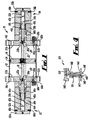
- FIG 1 there is shown a longitudinal, cross-sectional view of a pump in accordance with the present invention, the pump indicated generally by reference numeral 10.
- the pump 10 is illustrated in more detail in Figures 2 and 3, which also show a main valve assembly 80 coupled to the pump 10, the valve assembly 80 also in accordance with the invention, and which show the pump 10 at various stages in a cycle of operation.
- the pump 10 comprises an actuating cylinder 12 and an actuating piston in the form of an air drive flange 16, which is mounted for reciprocating movement within the actuating cylinder 12.
- the pump also comprises a discharge cylinder 52a which is provided in a hydraulic end housing 38a, and a sleeve 40a which is optionally releasably mounted within the discharge cylinder 52a, to thereby define an operating diameter 42a of the cylinder.
- a discharge piston 30a is coupled to the flange 16 and mounted for reciprocating movement within the sleeve 40a, to discharge fluid from the discharge cylinder 52a.
- the pump 10 is operated to pump a fluid by controlling reciprocating movement of the flange 16 within the actuating cylinder 12. This is achieved by controlling the supply of actuating fluid (in this case, compressed air) to the actuating cylinder 12.
- actuating fluid in this case, compressed air
- the discharge piston 30a by virtue of its connection to the flange 16, is reciprocated back and forth within the sleeve 40a during movement of the flange 16, and thus repeatedly charges the discharge cylinder 52a (drawing fluid in through an inlet 56a, having a check valve) and discharges the cylinder 52a (expelling the fluid through an outlet 58a, also having a check valve).
- the sleeve 40a is optionally releasably mounted within the discharge cylinder 52a, which facilitates maintenance and/or replacement.
- the sleeve 40a may be replaced with a sleeve of a different internal diameter, which enables the flow characteristics of the pump to be adjusted. For example, by replacing the sleeve 40a with a sleeve of a smaller internal diameter, a smaller volume of fluid is drawn into the discharge cylinder 52a on each cycle of the discharge piston 30a.
- the diameter of the replacement sleeve 40a is smaller, the resultant pressure of the discharged fluid is higher; this is due to the corresponding smaller piston area defined by the replacement sleeve, which will be described below.
- the valve assembly 80 includes an inlet valve in the form of an adjustable needle valve 83, which controls the entry of air into the valve assembly 80 through an inlet 81, for driving the pump 10.
- an inlet valve in the form of an adjustable needle valve 83, which controls the entry of air into the valve assembly 80 through an inlet 81, for driving the pump 10.
- Providing a valve assembly 80 with such an inlet valve 83 facilitates accurate control of the flow of actuating fluid to the valve assembly 80. This in turn facilitates control of the flow of actuating fluid to the pump 10, which permits one or more operating characteristics of the pump to be varied, as will be described in more detail below.
- valve assembly 80 is provided separately from the pump 10 in that it is mounted externally of the pump, either on a part of the pump such as the air cylinder 12, or to a support frame or structure (not shown). In either case, the valve assembly 80 is connected to the pump 10 through appropriate control lines and pipes, as will also be described below.
- the pump 10 is a dual-piston reciprocating pump, for supplying a substantially constant fluid output, and includes two discharge pistons 52a, 52b at opposite ends 32 and 34 of the pump. Like components of the pump components at the end 32 with those at the end 34 share the same reference numerals, but with the suffix 'a' generally replaced with the suffix 'b'.
- the air cylinder 12 includes end caps 14a,b and a drive shaft 18 is provided which extends along a longitudinal axis of the cylinder 10 and through apertures 20a,b in the end caps 14a,b.
- the air drive flange 16 is connected to the portion 22 of the shaft 18 within the cylinder 12, and seals 24 are provided around the outer circumference of the flange 16.
- the discharge pistons 30a,b are connected to the drive shaft 18 via threaded connections 36a,b thereby allowing the pistons to be readily changed out.
- the hydraulic end housings 38a,b are threadably connected to the respective end caps 14a,b so that they can be removed easily for access to components of the pump.
- the hydraulic end housings 38a,b define the discharge cylinders 52a,b and are aligned with the longitudinal axis of the pump, such that the drive shaft 18 with pistons 30a,b are able to slideably move relative to the discharge cylinders.
- the housings 38a,b include respective end portions or caps 50a,b.
- the hydraulic end housings 38a,b receive the sleeves or cartridges 40a,b, which have hydraulic seals 44a,b which seal between the cartridges 40a,b and the outer surface of the pistons 30a,b.
- the diameter 42a,b defined by the cartridges 40a,b and seals 44a,b are matched to that of the pistons 30a,b such that the pistons fit snugly and slideably within the cartridges.
- seals 44a,b and cartridge 40a,b are secured in position in the hydraulic end housings 38a,b by packing nuts 46a,b which are threadably connected to the housings. In this way, the cartridges are removable from the end housings and the pump.
- a maximum, operating volume of the discharge cylinders 52a,b are defined by front surfaces 54a,b of the pistons 30a,b, the inner surfaces of the cartridges 40a,b, and end portions 50a,b of the hydraulic end housings and depend upon the extent of movement of the pistons relative to the cartridges.
- Inlets 56a,b are provided for drawing in hydraulic fluid from an external reservoir, whilst the discharge pistons 30a,b move in a direction away from the respective first and second ends 32,34 of the pump. Also provided in the end housings are outlets 58a,b through which high-pressure fluid is discharged from the cylinders 52a,b under the force of the pistons 30a,b.
- the pump 10 is modular and the detachable hydraulic end housings 38a,b allow easy access to the pistons 30a,b and hydraulic seals 44a,b. This facilitates cleaning/maintenance and replacement without having to fully dismantle the pump 10.
- a piston may be changed out and replaced with a different piston as required by a user for a particular application.
- a smaller piston may be required to provide high-pressure, low-flow-rate output.
- the provision of different cartridge or insert sizes removes the need to provide pumps with different specifications for different jobs or purposes.
- the air cylinder is additionally provided with ports 57a,b extending through the cylinder end caps 14a,b. As will be described, the ports 57a,b provide a fluid connection to ends 26 and 28 of the air cylinder 12 for driving the pump 10.
- the pump 10 is shown in an operational configuration, connected to the main valve assembly 80.
- air is supplied to the air cylinder 12 under the control of the valve assembly 80, which comprises a valve main body in the form of a housing 98 and a valve member in the form of a shuttle valve 100.
- the shuttle valve 100 is mounted for reciprocating movement within the housing 98, and is provided with a number of flanges 102 having outer surfaces 104 which carry seals 106.
- the flanges 102 of the shuttle body thereby define a series of annular chambers 82, 84, 90 and 92 between the shuttle valve 100 and the valve housing 98, which serve for controlling air flow, as will be described below.
- the valve assembly 80 also includes an inlet 81 and an inlet valve in the form of an adjustable needle valve 83, through which air enters the valve assembly for driving the pump 10. Air enters the valve assembly 80 via the port 81, and flows into the chamber 82. In the portion of the pump cycle depicted in Figure 2, the shuttle valve is in a first position. Air provided to the chamber 82 exits through a first, primary pump flow port 85 and flows into the air cylinder 12 via a pipe 94a and the port 57a. This air enters the end 26 of the cylinder 12 under pressure, and exerts a pressure force on the drive flange 16.
- the end 28 of the air cylinder 12 is open to atmosphere, via the port 57b, a pipe 94b, a second primary pump flow port 87 (in the valve housing 98) and an exhaust port 89 (which opens on to the annular chamber 84).
- a pressure differential is created across the flange 16, which then moves towards the second end 34 of the pump, to a second position.
- the piston 30b connected to the drive shaft 18 acts against the fluid in the chamber 52b, providing a high-pressure output from outlet 58b.
- the pressure of the air provided to the air cylinder 12 is typically between 2 and 12 bar (approximately 30 to 175 psi), whilst the output pressure is in the region of 60,000 psi.
- the needle valve 83 is shown in more detail in the enlarged view of Figure 4, and comprises a base body 144 and a threaded shaft 146, with a handle 140 attached to a top end of the shaft, for turning the shaft in the base body 144.
- a passageway 150 is provided through the handle and opens into an area 151, for entry of air into the valve 83.
- the handle 140, and thus the shaft 146 can be rotated to lift the needle pin 145 away from a valve seat 147 in the base body 144. This facilitates air flow through the valve into the region 149 and thus into the valve chamber 82. Adjustment of the handle 140 position provides different rates of air flow through the valve 83. This may be set by manually turning the handle or by an automatic control arrangement (not shown).
- the needle valve 83 has a connecting portion 148 on the base body 144 which engages with the valve housing 98.
- needle valve 83 to control delivery of air for driving the pump 10 allows the operational characteristics of the pump 10 to be adjusted. Specifically, provision of the needle valve 83 allows control of the rate of flow of actuating fluid into the pump 10 independently of the air within the pipes 96a,b.
- valve assembly 80 is a self-contained unit that may be utilised with a range of different pumps, and may also be utilised to control operational characteristics of the pumps. Specifically the needle valve 83 allows the flow to be adjusted according to desired operational characteristics of the pump.
- valve assembly 80 may be easily maintained as it is not necessary to dismantle the pump to replace parts of the valve assembly.
- the valve assembly 80 can thus be maintained and repaired independently, which saves costs and reduces downtime.
- the pump 10 also comprises two pilot valves 60a,b which are biased closed, and which are opened via mechanical activation of valve pins 66a,b from inside the air cylinder 12.
- the length of the pins 66a,b is adjustable and the pins 66a,b protrude inwardly into the cylinder ends 26 and 28.
- the flange 16 strikes a valve pin 66b of the pilot valve 60b, and when the pin is depressed, the valve is opened.
- the pilot valves 60a,b are connected via pipes 96a,b to control fluid flow to the ports 88a,b of the valve assembly 80. Air is supplied to the pipes from a common pressure source (not shown) through ports 86a,b of the valve assembly 80 and annular end chambers 90 and 92 respectively. Air pressure in these pipes 96a,b and the chambers 90 and 92 determine the position of the shuttle valve 100 within the valve housing 98. In the position of Figure 2, the pressure in the chamber 90 is held at a higher level than that in the chamber 92 by the closed pilot valve 60b, creating a pressure differential across the shuttle valve 100 holding it in the Figure 2 position.
- the pump is shown following movement of the shuttle 100 to the opposite end of the valve housing 98.
- the chamber 82 of the valve assembly 80 opens onto the port 87, such that air is now provided to the end 28 of the air cylinder 12 through port 57b.
- air is supplied to the cylinder end 28 and forces the flange 16 and piston 30 to move toward the first end 32 of the pump 10.
- air exits the cylinder end 26 via port 57a and pipe 96a and back to the valve assembly 80.
- the return air enters port 85 and exhausts to the atmosphere through a port 126.
- the pilot valve 62b is released and closes, locking the shuttle 100 in the position of Figure 3.
- the different internal diameters 42a,b of the sleeves 40a,b result in different flow characteristics of the discharged fluid. For example, a larger volume of fluid is discharged from the cylinder 52a on each cycle of the piston 30a than on each cycle of the piston 30b. However, the smaller piston area of the piston 30b results in higher pressure output from the discharge cylinder 52b. By combining the outputs from the cylinders 52a and 52b, a balance of a good flow rate and pressure can be achieved.
- the pump 10 provides a number of other advantages.
- the pins 66a,b for triggering the switching of the stroke direction of the pump are adjustable in length. This allows the stroke length of the pump in either direction to be adjusted, i.e. arranging the pins to protrude further into the air cylinder 12 will shorten the stroke length.
- the valves containing these pins may be unscrewed to insert appropriate length pins 66a,b or the lengths of the pins could be adjusted externally without needing to unscrew the valve. In either case, the pins and stroke length can be adjusted easily without dismantling the pump or providing a different size cylinder, which would otherwise be necessary.
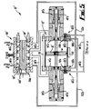
- FIG 5 there is shown a longitudinal, cross-sectional view of a reciprocating pump in accordance with an alternative embodiment of the present invention, the pump indicated generally by reference numeral 10'.
- the pump 10' Like components of the pump 10' with the pump 10 of Figs 1 to 4 share the same reference numerals, with the addition of the suffix'. Only significant differences between the pump 10' and the pump 10 will be described in detail herein.
- the pump 10' includes pilot valves 60'a and 60'b which govern the position of a shuttle valve 100', in a similar fashion to the valves 60a, 60b of the pump 10.
- end caps 14'a and 14'b of an actuating cylinder 12' include bleed vents 108a, 108b which open on to bores 110a, 110b in which the respective valves 60'a, 60'b are mounted.
- the bleed vent 108a is coupled to a fluid outlet line 112a which is in fluid communication with a chamber 90' of the valve assembly 80'.
- the bleed vent 108b is coupled by a fluid outlet line 112b to a chamber 92' at an opposite end of the valve 80'.
- valves 60'a and 60'b are coupled via fluid supply lines 96'a and 96'b to a common pilot pressure source (not shown).
- Ports 86'a and 86'b of the shuttle valve 80' carry one-way valves (not shown), and permit exhaust of air from the chambers 92' and 90', respectively.
- the pump 10 operates as follows. In use and during movement of a flange 16' of the pump 10' to the right, as shown in Figure 5, the flange 16' comes into contact with a pin 66'b of the pilot valve 60'b. This causes the valve 60'b to open, thereby permitting fluid communication between the pilot pressure source and the chamber 92', through the supply line 96'b and the outlet line 112b. The valve 60'a is closed, and the fluid supplied to chamber 92' causes the shuttle valve 100' to move to the right, exhausting the air in chamber 90' through the port 86'b. In a similar fashion to the valve assembly 80 of the pump 10, this switches flow into the actuating cylinder 12', and reverses the flange 16'.
- the pump 10' includes sleeves 40'a and 40'b which are of similar internal diameters, and thus illustrates a situation where it is desired to have similar discharge from each discharge piston 30'a and 30'b. Additionally, Figure 5 illustrates clamping bolts 116 which secure the cylinder flanges 14'a, 14'b together.
- FIG 6 there is shown a longitudinal, cross-sectional view of a main valve assembly forming part of a reciprocating pump in accordance with a further alternative embodiment of the present invention, the main valve assembly indicated generally by reference numeral 80''.
- the valve assembly 80'' typically forms part of a pump similar to the pump 10' shown in Figure 5, and thus may replace the valve assembly 80'.
- the valve assembly 80" is shown in Figure 6 and described, the remaining components of the pump being as shown in Figure 5. Only the differences between the assemblies 80'' and 80' will be described herein in detail, and like components of the valve assembly 80'' with the valve assemblies of Figs 1 to 4 and Fig 5 share the same reference numerals, with the addition of the suffix ".
- the valve assembly 80" includes a shuttle 100" of slightly different shape to the shuttle 100' of the valve assembly 80'.
- the shuttle 100'' includes shoulders 118, 120 which abut end caps 122, 124 respectively at each extreme extent of travel of the shuttle 100''.
- These end caps 122, 124 are threadably coupled to a housing 98'' of the valve assembly 80'', in a similar fashion to the valve assemblies shown in Figures 1 to 5. This permits removal of the shuttle 100" for maintenance/replacement.
- the shoulders 118, 120 define maximum extents of movement of the shuttle 100", and thus the position of the shuttle 100'' in relation to the various ports 85''; 86''a,b; 87''; and 88''a,b.
- end cap 124 defines an outlet 126 from an end chamber 128 which is of larger diameter than similar vent or bleed ports from the valve assemblies shown in Figures 1 to 5. This provides improved exhaust of air from the chamber 128 in use of the valve assembly 80". Operation of the valve assembly 80" is otherwise as described in relation to the valve assembly 80' of Figure 5.
- FIGS. 7 and 8 there are shown longitudinal, cross-sectional views of a main valve assembly forming part of a reciprocating pump in accordance with a preferred embodiment of the present invention, the valve assembly indicated generally by reference numeral 80''' and shown in the Figures at respective opposite extents of travel of a shuttle 100''' of the valve assembly.
- valve assembly 80''' is provided as part of a reciprocating pump similar to that shown in Figure 5, save that the valve assembly 80' has been replaced with the valve assembly 80'''.
- the remaining components of the pump have been omitted, for ease of illustration.
- valve assembly 80''' and the previously described valve assemblies will be described herein in detail.
- Like components of the valve assembly 80''' with the valve assemblies of Figs 1 to 4, Fig 5 or Fig 6 share the same reference numerals, with the addition of the suffix '''.
- a housing 98''' of the valve assembly 80''' includes a number of flow ports 130a and 130b (two of each shown) spaced around a circumference of the housing 98'''.
- Outer seal rings 132a, 132b are mounted on the housing 98 in abutment with a central flange 134, and are secured by bolts (not shown) which extend through passages 136a,b and engage in the flange 134.
- the seal rings 132a,b define main flow ports (not shown) similar to the ports 85'' and 87'' of the valve assembly 80''. These main flow ports open onto annular chambers 138a,b between the seal rings 132a,b and the housing 98''', as do the flow ports 130a, 130b.
- valve assembly 80''' This provides fluid communication between the valve assembly 80''' and the cylinder of the pump (such as the cylinder 12' of the pump 10' shown in Figure 5).
- This arrangement of the flow ports 130a,b spaced around the circumference of the housing 98''', and of the main flow ports opening onto the annular chambers 138a,b provides enhanced flow of air to and from the cylinder in use of the valve assembly 80'''.
- end caps 122''' and 124''' of the valve assembly 80''' have enlarged outlets 126'''a, 126'''b, to provide enhanced flow of exhaust air.
- the shuttle 100''' also includes a number of exhaust ports 140 and 142 (five of each shown) spaced around a circumference of the shuttle valve, to enhance flow of exhaust air.
- the shuttle 100''' includes a throughbore 144 which provides for fluid communication between the exhaust ports 140, 142 and the respective outlets 126'''a,b. The shuttle 100''' is shown following movement to the opposite extent of its travel in Figure 8.
- valve assembly 80 iv of a reciprocating pump in accordance with a further alternative embodiment of the present invention
- valve assembly 80 iv is provided as part of a reciprocating pump similar to that shown in Figure 5, save that the valve assembly 80' has been replaced with the valve assembly 80 iv .
- the remaining components of the pump have been omitted, for ease of illustration.
- valve assembly 80 iv and the previously described valve assemblies will be described herein in detail.
- Like components of the valve assembly 80 iv with the assemblies of Figs 1 to 4, Fig 5, Fig 6 or Figs 7 and 8 share the same reference numerals, with the addition of the suffix iv .
- valve assembly 80 iv is essentially the same as the valve assembly 80''', save that the internal diameter of the shuttle 100''' throughbore 144 is 3 ⁇ 4", whereas a throughbore 144 iv of the shuttle 100 iv is 1" to provide enhanced air flow. Additionally, internal diameters of end caps 122 iv and 124 iv have been enlarged to account for the larger diameter shuttle 100 iv . Operation of the valve assemblies 80''' and 80 iv is otherwise as described in relation to the valve assembly 80' of Figure 5.
- the end housings may be detached, allowing the piston to be unscrewed and replaced with a different diameter piston to suit needs.
- Cartridges provided in the housing that compliment the piston and house the hydraulic seals can similarly be unscrewed, removed and replaced. Such replacement can be carried out with ease and can be carried out with the pump in situ as part of a larger system. Hydraulic seals can be easily accessed, maintained and replaced.
- the present pump 10 mitigates the need to dismantle the pump or to change out the entire pump with a new pump when different pump characteristics are required. This saves costs relating to the purchase of parts and operational downtime for repair and maintenance.
- the discharge pistons may be directly threadably coupled to the actuating piston, such that the entire piston is released from the actuating piston when it is desired to changeover for a discharge piston of a different diameter.
Applications Claiming Priority (1)
| Application Number | Priority Date | Filing Date | Title |
|---|---|---|---|
| GBGB0520879.8A GB0520879D0 (en) | 2005-10-14 | 2005-10-14 | A valve assembly |
Publications (2)
| Publication Number | Publication Date |
|---|---|
| EP1775468A2 true EP1775468A2 (de) | 2007-04-18 |
| EP1775468A3 EP1775468A3 (de) | 2009-03-04 |
Family
ID=35451727
Family Applications (1)
| Application Number | Title | Priority Date | Filing Date |
|---|---|---|---|
| EP06255283A Withdrawn EP1775468A3 (de) | 2005-10-14 | 2006-10-13 | Ventileinrichtung |
Country Status (3)
| Country | Link |
|---|---|
| US (1) | US20070253847A1 (de) |
| EP (1) | EP1775468A3 (de) |
| GB (1) | GB0520879D0 (de) |
Families Citing this family (3)
| Publication number | Priority date | Publication date | Assignee | Title |
|---|---|---|---|---|
| CN103615365B (zh) * | 2013-11-26 | 2015-09-30 | 浙江理工大学 | 一种集成阀式气驱液增压泵 |
| US10801493B2 (en) * | 2017-12-14 | 2020-10-13 | William E. Howseman, Jr. | Positive displacement reciprocating pump assembly for dispensing predeterminedly precise amounts of fluid during both the up and down strokes of the pump piston |
| NL2021314B1 (en) * | 2018-07-16 | 2020-01-24 | Noord Jan | Reciprocating piston motor, motor-pump assembly and method for driving a pump |
Citations (9)
| Publication number | Priority date | Publication date | Assignee | Title |
|---|---|---|---|---|
| GB530050A (en) * | 1939-06-02 | 1940-12-04 | Byron Jackson Co | Improvements in or relating to hydraulically actuated pumps |
| US3368458A (en) * | 1965-10-24 | 1968-02-13 | Lawrence P. Shinaver | Hydraulic motor |
| US3387563A (en) * | 1967-03-22 | 1968-06-11 | James F. Williams | Chemical injector |
| US3556689A (en) * | 1969-03-05 | 1971-01-19 | Valentine Hechler | Pump for proportioning device |
| US3637328A (en) * | 1970-02-26 | 1972-01-25 | Inouye Shokai Kk | Slurry-pumping means |
| GB1420424A (en) * | 1973-01-12 | 1976-01-07 | Flow Research Inc | High pressure fluid intensifier and method |
| US4439114A (en) * | 1981-03-19 | 1984-03-27 | Kimmell Garman O | Pumping system |
| US4526000A (en) * | 1983-10-18 | 1985-07-02 | Mccartney Manufacturing Co., Inc. | Pressure intensifier |
| GB2356432A (en) * | 1999-11-18 | 2001-05-23 | Colin Pearson | Fluid powered pump with valve control |
Family Cites Families (3)
| Publication number | Priority date | Publication date | Assignee | Title |
|---|---|---|---|---|
| US3838946A (en) * | 1971-07-12 | 1974-10-01 | Dorr Oliver Inc | Air pressure-actuated double-acting diaphragm pump |
| US4029440A (en) * | 1975-08-21 | 1977-06-14 | Flow Industries, Inc. | High pressure fluid intensifier and method |
| GB0520878D0 (en) * | 2005-10-14 | 2005-11-23 | Stamper Eric S | Improved pump |
-
2005
- 2005-10-14 GB GBGB0520879.8A patent/GB0520879D0/en not_active Ceased
-
2006
- 2006-10-12 US US11/549,039 patent/US20070253847A1/en not_active Abandoned
- 2006-10-13 EP EP06255283A patent/EP1775468A3/de not_active Withdrawn
Patent Citations (9)
| Publication number | Priority date | Publication date | Assignee | Title |
|---|---|---|---|---|
| GB530050A (en) * | 1939-06-02 | 1940-12-04 | Byron Jackson Co | Improvements in or relating to hydraulically actuated pumps |
| US3368458A (en) * | 1965-10-24 | 1968-02-13 | Lawrence P. Shinaver | Hydraulic motor |
| US3387563A (en) * | 1967-03-22 | 1968-06-11 | James F. Williams | Chemical injector |
| US3556689A (en) * | 1969-03-05 | 1971-01-19 | Valentine Hechler | Pump for proportioning device |
| US3637328A (en) * | 1970-02-26 | 1972-01-25 | Inouye Shokai Kk | Slurry-pumping means |
| GB1420424A (en) * | 1973-01-12 | 1976-01-07 | Flow Research Inc | High pressure fluid intensifier and method |
| US4439114A (en) * | 1981-03-19 | 1984-03-27 | Kimmell Garman O | Pumping system |
| US4526000A (en) * | 1983-10-18 | 1985-07-02 | Mccartney Manufacturing Co., Inc. | Pressure intensifier |
| GB2356432A (en) * | 1999-11-18 | 2001-05-23 | Colin Pearson | Fluid powered pump with valve control |
Also Published As
| Publication number | Publication date |
|---|---|
| GB0520879D0 (en) | 2005-11-23 |
| US20070253847A1 (en) | 2007-11-01 |
| EP1775468A3 (de) | 2009-03-04 |
Similar Documents
| Publication | Publication Date | Title |
|---|---|---|
| EP1775469A2 (de) | Pumpe | |
| US20080240944A1 (en) | Air-Operated Pump | |
| EP0708244B1 (de) | Doppelmembranpumpe | |
| CN101382156A (zh) | 流量控制阀和带有该流量控制阀的缸设备 | |
| EP0090609B1 (de) | Hydraulischer Verstärker | |
| US5655885A (en) | Reciprocating piston pump with modular fluid subassembly | |
| EP0832359B1 (de) | Pneumatische pumpe | |
| EP1775468A2 (de) | Ventileinrichtung | |
| US7204087B2 (en) | Hydraulic tool | |
| US8186972B1 (en) | Multi-stage expansible chamber pneumatic system | |
| KR20190133257A (ko) | 증압장치 | |
| US5334003A (en) | Air valving mechanism, in combination with a double diaphragm pump subassembly | |
| EP3209884B1 (de) | Luftmotor | |
| US20040018106A1 (en) | Compressor and method with an improved inlet and discharge valve arrangement | |
| AU2011252736B2 (en) | An air motor | |
| KR0136449B1 (ko) | 공압식 윤활 펌프 | |
| US7367785B2 (en) | Reduced icing valves and gas-driven motor and reciprocating pump incorporating same | |
| KR20040097936A (ko) | 격막 펌프 시스템 | |
| US7284961B2 (en) | Pumping system, replacement kit including piston and/or cylinder, and method for pumping system maintenance | |
| US5067515A (en) | Compact spray gun | |
| US4925104A (en) | Compact spray gun | |
| US7625190B2 (en) | Crossover switching valve | |
| GB2302712A (en) | Air-operated hydraulic motor | |
| KR102491699B1 (ko) | 도장용 다이어프램 피스톤 펌프 | |
| CN212616519U (zh) | 一种组合开关 |
Legal Events
| Date | Code | Title | Description |
|---|---|---|---|
| PUAI | Public reference made under article 153(3) epc to a published international application that has entered the european phase |
Free format text: ORIGINAL CODE: 0009012 |
|
| AK | Designated contracting states |
Kind code of ref document: A2 Designated state(s): AT BE BG CH CY CZ DE DK EE ES FI FR GB GR HU IE IS IT LI LT LU LV MC NL PL PT RO SE SI SK TR |
|
| AX | Request for extension of the european patent |
Extension state: AL BA HR MK YU |
|
| PUAL | Search report despatched |
Free format text: ORIGINAL CODE: 0009013 |
|
| AK | Designated contracting states |
Kind code of ref document: A3 Designated state(s): AT BE BG CH CY CZ DE DK EE ES FI FR GB GR HU IE IS IT LI LT LU LV MC NL PL PT RO SE SI SK TR |
|
| AX | Request for extension of the european patent |
Extension state: AL BA HR MK RS |
|
| 17P | Request for examination filed |
Effective date: 20090903 |
|
| AKX | Designation fees paid |
Designated state(s): AT BE BG CH CY CZ DE DK EE ES FI FR GB GR HU IE IS IT LI LT LU LV MC NL PL PT RO SE SI SK TR |
|
| 17Q | First examination report despatched |
Effective date: 20091110 |
|
| STAA | Information on the status of an ep patent application or granted ep patent |
Free format text: STATUS: THE APPLICATION IS DEEMED TO BE WITHDRAWN |
|
| 18D | Application deemed to be withdrawn |
Effective date: 20100323 |