EP1775391A1 - Boom/arm member for construction machine, having high welded portion fatigue strength, and method of improving the fatigue strength - Google Patents
Boom/arm member for construction machine, having high welded portion fatigue strength, and method of improving the fatigue strength Download PDFInfo
- Publication number
- EP1775391A1 EP1775391A1 EP05766177A EP05766177A EP1775391A1 EP 1775391 A1 EP1775391 A1 EP 1775391A1 EP 05766177 A EP05766177 A EP 05766177A EP 05766177 A EP05766177 A EP 05766177A EP 1775391 A1 EP1775391 A1 EP 1775391A1
- Authority
- EP
- European Patent Office
- Prior art keywords
- boom
- arm
- fatigue strength
- construction machine
- toes
- Prior art date
- Legal status (The legal status is an assumption and is not a legal conclusion. Google has not performed a legal analysis and makes no representation as to the accuracy of the status listed.)
- Granted
Links
Images



Classifications
-
- B—PERFORMING OPERATIONS; TRANSPORTING
- B23—MACHINE TOOLS; METAL-WORKING NOT OTHERWISE PROVIDED FOR
- B23K—SOLDERING OR UNSOLDERING; WELDING; CLADDING OR PLATING BY SOLDERING OR WELDING; CUTTING BY APPLYING HEAT LOCALLY, e.g. FLAME CUTTING; WORKING BY LASER BEAM
- B23K31/00—Processes relevant to this subclass, specially adapted for particular articles or purposes, but not covered by any single one of main groups B23K1/00 - B23K28/00
- B23K31/12—Processes relevant to this subclass, specially adapted for particular articles or purposes, but not covered by any single one of main groups B23K1/00 - B23K28/00 relating to investigating the properties, e.g. the weldability, of materials
-
- B—PERFORMING OPERATIONS; TRANSPORTING
- B23—MACHINE TOOLS; METAL-WORKING NOT OTHERWISE PROVIDED FOR
- B23K—SOLDERING OR UNSOLDERING; WELDING; CLADDING OR PLATING BY SOLDERING OR WELDING; CUTTING BY APPLYING HEAT LOCALLY, e.g. FLAME CUTTING; WORKING BY LASER BEAM
- B23K31/00—Processes relevant to this subclass, specially adapted for particular articles or purposes, but not covered by any single one of main groups B23K1/00 - B23K28/00
- B23K31/02—Processes relevant to this subclass, specially adapted for particular articles or purposes, but not covered by any single one of main groups B23K1/00 - B23K28/00 relating to soldering or welding
-
- B—PERFORMING OPERATIONS; TRANSPORTING
- B23—MACHINE TOOLS; METAL-WORKING NOT OTHERWISE PROVIDED FOR
- B23K—SOLDERING OR UNSOLDERING; WELDING; CLADDING OR PLATING BY SOLDERING OR WELDING; CUTTING BY APPLYING HEAT LOCALLY, e.g. FLAME CUTTING; WORKING BY LASER BEAM
- B23K33/00—Specially-profiled edge portions of workpieces for making soldering or welding connections; Filling the seams formed thereby
-
- C—CHEMISTRY; METALLURGY
- C21—METALLURGY OF IRON
- C21D—MODIFYING THE PHYSICAL STRUCTURE OF FERROUS METALS; GENERAL DEVICES FOR HEAT TREATMENT OF FERROUS OR NON-FERROUS METALS OR ALLOYS; MAKING METAL MALLEABLE, e.g. BY DECARBURISATION OR TEMPERING
- C21D7/00—Modifying the physical properties of iron or steel by deformation
- C21D7/02—Modifying the physical properties of iron or steel by deformation by cold working
- C21D7/04—Modifying the physical properties of iron or steel by deformation by cold working of the surface
-
- C—CHEMISTRY; METALLURGY
- C21—METALLURGY OF IRON
- C21D—MODIFYING THE PHYSICAL STRUCTURE OF FERROUS METALS; GENERAL DEVICES FOR HEAT TREATMENT OF FERROUS OR NON-FERROUS METALS OR ALLOYS; MAKING METAL MALLEABLE, e.g. BY DECARBURISATION OR TEMPERING
- C21D9/00—Heat treatment, e.g. annealing, hardening, quenching or tempering, adapted for particular articles; Furnaces therefor
- C21D9/50—Heat treatment, e.g. annealing, hardening, quenching or tempering, adapted for particular articles; Furnaces therefor for welded joints
-
- E—FIXED CONSTRUCTIONS
- E02—HYDRAULIC ENGINEERING; FOUNDATIONS; SOIL SHIFTING
- E02F—DREDGING; SOIL-SHIFTING
- E02F3/00—Dredgers; Soil-shifting machines
- E02F3/04—Dredgers; Soil-shifting machines mechanically-driven
- E02F3/28—Dredgers; Soil-shifting machines mechanically-driven with digging tools mounted on a dipper- or bucket-arm, i.e. there is either one arm or a pair of arms, e.g. dippers, buckets
- E02F3/36—Component parts
- E02F3/38—Cantilever beams, i.e. booms;, e.g. manufacturing processes, forms, geometry or materials used for booms; Dipper-arms, e.g. manufacturing processes, forms, geometry or materials used for dipper-arms; Bucket-arms
-
- E—FIXED CONSTRUCTIONS
- E02—HYDRAULIC ENGINEERING; FOUNDATIONS; SOIL SHIFTING
- E02F—DREDGING; SOIL-SHIFTING
- E02F9/00—Component parts of dredgers or soil-shifting machines, not restricted to one of the kinds covered by groups E02F3/00 - E02F7/00
- E02F9/14—Booms only for booms with cable suspension arrangements; Cable suspensions
-
- B—PERFORMING OPERATIONS; TRANSPORTING
- B25—HAND TOOLS; PORTABLE POWER-DRIVEN TOOLS; MANIPULATORS
- B25D—PERCUSSIVE TOOLS
- B25D2250/00—General details of portable percussive tools; Components used in portable percussive tools
- B25D2250/275—Tools having at least two similar components
- B25D2250/285—Tools having three or more similar components, e.g. three motors
- B25D2250/291—Tools having three or more parallel bits, e.g. needle guns
Definitions
- the present invention relates to a boom and arm member of a construction machine excellent in weld zone fatigue strength and a method of improvement of its fatigue strength.
- the fatigue strength of a weld zone is remarkably lower than the fatigue strength of the matrix material.
- the main reasons are known to be of the stress concentration at the weld toe, the formation of tensile residual stress sites at the weld toe, and the growth of the crystal grains of the weld heat affected zone.
- grinding has the problem of poor work efficiency and further of its effect being largely governed by the skill of the operator, e.g., with over grinding of the weld zones resulting in a reduction in the joint strength.
- SR treatment has the problem that it requires a large sized heat treatment furnace and involves tremendous capital costs and operating costs.
- Japanese Patent Publication (A) No. 2003-113418 proposes the method of pretreating locations of a metal material where fatigue would become a problem, then treating it by ultrasonic shock waves and further then inspecting it for quality assurance so as to improve the fatigue life of the metal material and discloses that ultrasonic shock wave treatment causes the weld toes to deform with curvature and the degree of stress concentration to change.
- Japanese Patent Publication (A) No. 2004-130313 proposes a method of improving the fatigue strength by striking the vicinity of the top parts of weld toes of fillet weld joints, where two overlapping ends are welded together, by an ultrasonic vibration terminal.
- the present invention solves the above-mentioned problem of the prior art and has as its object the provision of a boom and arm member of a construction machine excellent in weld zone fatigue strength and a method of improvement of its fatigue strength.
- the present invention was made as a result of in-depth studies to achieve the above object and provides a boom and arm member of a construction machine excellent in weld zone fatigue strength providing the toes of full penetrated weld zones of a boom and arm member of a construction machine with vibration strike marks by a vibration terminal and a method of improvement of its fatigue strength and has as its gist the following content as described in the claim section:
- FIG. 1 to FIG. 3 are views illustrating a boom and arm of a construction machine covered by the present invention.
- FIG. 1 is an overall schematic view of an excavator shown as an example of a construction machine by a perspective view, wherein 1 indicates a cab, 2 a crawler, 3 a boom, 4 an arm, and 5 a bucket.
- the boom 3 or arm 4 is acted on by a repeated load comprised of an axial force and bending force and the weld zones sometimes crack causing fatigue damage.
- FIG. 2 is a perspective view of the structure of a boom
- FIG. 3 schematically shows the structure of the arm by a side view.
- 6 indicates a top plate, 7 a side plate, 8 a bottom plate, 9 a reinforcing partition plate, 10 a bearing part cast bracket, and 11 a cylinder fastening part.
- the boom and arm have box structures. In cross-section, they form rectangular closed cross-sectional structures resistant to not only deformation in the axial direction but also bending deformation.
- FIG. 4 is a view illustrating the cross-section of a boom and arm member of the present invention.
- 6 indicates a top plate, 7 a side plate, 8 a bottom plate, 12 a weld metal, 13 a stop part, and 14 a vibration terminal.
- the present invention is a boom and arm member of a construction machine characterized by having vibration strike marks at stop parts of full penetrated weld zones of the boom and arm member.
- the present invention strikes the toes of full penetrated weld zones 13 by a vibration terminal 14 to impart vibration strike marks to toes 13 most susceptible to stress concentration and convert the residual stress of the toes 13 to compressive residual stress and thereby improve the weld zone fatigue strength.
- a "full penetrated weld zone” means a weld zone where the weld metal 12 spans the entire thickness direction of a steel plate being welded.
- the weld zones for the vibration striking treatment are limited to full penetrated weld zones because if not full penetrated welds, unwelded parts will remain at the weld locations of the weld material, stress concentration will occur at the front ends of the unwelded parts (root parts), and fatigue cracks will easily occur and propagate from the root parts. Further, the root parts end up being buried inside the weld zones, so even if applying vibration striking treatment from the outside, it is not possible to change the residual stress of the front regions of the root parts from tensile to compressive stress.
- the residual stress of the bottom surfaces of the vibration strike marks is preferably made a 10 MPa or more compressive residual stress.
- the materials of the boom and arm are not critical, but since they are frequently used for construction machines, SS400, SM400, SM490, SM570, and other structural steels are preferable.
- FIG. 5 and FIG. 6 are views schematically showing typical examples of the weld zones of a boom and arm to which the present invention is applied by cross-sectional views.
- 8 indicates a bottom plate, 9 a reinforcing partition plate, 12 a weld metal, 13 a toes, and 14 a vibration terminal.
- FIG. 5 indicates the case of butt welding bottom plates 8
- FIG. 6 indicates,the case of T-welding a bottom plate 8 and reinforcing partition plate 9.
- weld toe to which the present invention is applied should be a full penetrated weld zone. It may be any of toes of steel plate weld zones of top plates, side plates, and bottom plates forming the boom and arm, toes of steel plate weld zones of reinforcing partition steel plates and the boom and arm in the boom and arm, toes of steel plate weld zones with bearing part cast brackets, and/or toes of the weld zones of the parts of the bucket, arm, and boom to which two ends of cylinders are fastened.
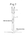
- FIG. 7 and FIG. 8 are a view illustrating a vibration terminal used in the present invention.
- 14 indicates a vibration terminal, and 15 a vibrator.
- the surface of the weld toe is struck by the vibration terminal 14.
- the vibrator 15 is used to make the front end of the vibration terminal 14 vibrate and apply vibration striking to the surface of the weld toe at a 10 Hz to 50 kHz frequency by a 0.01 to 4 kW work rate.
- vibration striking at a 10 Hz to 50 kHz frequency and a 0.01 to 4kW work rate it is possible to make the residual stress of the bottom surface of the vibration strike marks a 10 MPa or more compressive residual stress and possible to make the crystal grain size of the steel material 5 ⁇ m or less.
- the mechanism by which striking a weld toe at its surface causes the residual stress to become compressive residual stress is that using a vibration terminal 14 made to vibrate at a 10 Hz to 50 kHz frequency to strike it by a 0.01 to 4 kW work rate causes the toe to plastically flow at its surface to form strike marks along with that form sites for compressive residual stress near the surface.
- the mechanism by which the crystal grains are made finer is believed to be that using the vibration terminal 14, made to vibrate at a 10 Hz to 50 kHz frequency, strike the surface by a 0.01 to 4 kW work rate causes the surface of the toe to generate work heat and that repeated striking in an insulated state where this work heat cannot escape causes the same effect as with hot forging.
- the reason for limitation of the frequency of the vibration terminal 14 to 10 Hz or more is that if less than 10 Hz, the insulating effect of the heat due to the striking cannot be obtained, while the reason for limitation to a frequency of not more than 50 kHz is that the ultrasonic waves or other frequency obtained by a vibrator able to be used industrially is generally not more than 50 kHz.
- the work rate of the vibration terminal 14 is made 0.01 kW or more because if less than 0.01 kW, the treatment time required for the striking treatment becomes too long. It is made not more than 4 kW because even if striking the surface with a work rate over this, the effect is saturated, so the economic advantage falls.
- the vibration terminal 14 is a rod shape as shown in FIG. 7. If the cross-sectional area by which the front end of the rod contacts the subject metal product is too small, the treatment time becomes long, while if the cross-sectional area is too large, the effect of increasing the grain fineness is not sufficient, so the cross-sectional area is preferably made 0.01 mm 2 to 100 mm 2 .
- a plurality of vibration terminals 14 are used bundled together and the bundled vibration terminals 14 as a whole are made to vibrate simultaneously in the vertical direction and the horizontal direction.
- a plurality of vibrators 15 are provided to cause vibration in each of the vertical direction and horizontal direction.
- the vibration terminal 14 By making the vibration terminal 14 simultaneously vibrate vertically and horizontally and strike the surface of the weld toe in this way, formation of texture is suppressed and the crystal grains can be made equiaxial, so the surface layer part can be made finer in crystal structure.
- vibration terminal 14 may be a single terminal made to vibrate vertically and horizontally. Further, instead of horizontal vibration, the vibration terminal may be made to rotate or rock to obtain similar effects.
- 6 indicates a top plate, 7 a side plate, 8 a bottom plate, and 12 a weld metal. As shown in FIG. 9, the toes of the weld metal 12 were treated by vibration striking using the afore-mentioned single vibration terminal.
- the X-ray Sin2 ⁇ method was used to measure the residual stress of the bottom of the strike marks, whereupon the residual stress in the direction parallel to the weld bead was -251 MPa to -431 MPa and the residual stress in the direction vertical to the weld bead was -85 MPa to -286 MPa - in each case compressive residual stress.
- the bottom surface of the vibration strike marks had an average value of the crystal grain size of the steel material of 1.0 ⁇ m.
- a boom and arm member of a construction machine superior in weld zone fatigue strength and a method of improvement of its fatigue strength by providing the toes of full penetrated weld zones of a boom and arm member of a construction machine with vibration strike marks by a vibration terminal.
Landscapes
- Engineering & Computer Science (AREA)
- Mechanical Engineering (AREA)
- Chemical & Material Sciences (AREA)
- General Engineering & Computer Science (AREA)
- Metallurgy (AREA)
- Structural Engineering (AREA)
- Organic Chemistry (AREA)
- Civil Engineering (AREA)
- Mining & Mineral Resources (AREA)
- Crystallography & Structural Chemistry (AREA)
- Materials Engineering (AREA)
- Thermal Sciences (AREA)
- Physics & Mathematics (AREA)
- Butt Welding And Welding Of Specific Article (AREA)
- Shovels (AREA)
- Vehicle Body Suspensions (AREA)
- Body Structure For Vehicles (AREA)
Abstract
Description
- The present invention relates to a boom and arm member of a construction machine excellent in weld zone fatigue strength and a method of improvement of its fatigue strength.
- The boom and arm member of an excavator or other construction machine is constantly subjected to repeated load. It is therefore necessary to give sufficient consideration to the safety of weld zones against fatigue during operation of the construction machine.
- In general, the fatigue strength of a weld zone is remarkably lower than the fatigue strength of the matrix material. The main reasons are known to be of the stress concentration at the weld toe, the formation of tensile residual stress sites at the weld toe, and the growth of the crystal grains of the weld heat affected zone.
- As measures against this, in the past the method of grinding the weld zones to prevent the concentration of stress at the weld zones and the method of placing the welded boom and arm member in a heat treatment furnace for post-heat treatment in so-called "SR treatment" to reduce the tensile residual stress on the weld zones have been used.
- However, grinding has the problem of poor work efficiency and further of its effect being largely governed by the skill of the operator, e.g., with over grinding of the weld zones resulting in a reduction in the joint strength.
- Further, SR treatment has the problem that it requires a large sized heat treatment furnace and involves tremendous capital costs and operating costs.
- Further,
Japanese Patent Publication (A) No. 2003-113418 - Further,
Japanese Patent Publication (A) No. 2004-130313 - However, in these proposals, the case of applying ultrasonic striking treatment to the boom and arm of a construction machine and the conditions for the same were not studied.
- The present invention solves the above-mentioned problem of the prior art and has as its object the provision of a boom and arm member of a construction machine excellent in weld zone fatigue strength and a method of improvement of its fatigue strength.
- The present invention was made as a result of in-depth studies to achieve the above object and provides a boom and arm member of a construction machine excellent in weld zone fatigue strength providing the toes of full penetrated weld zones of a boom and arm member of a construction machine with vibration strike marks by a vibration terminal and a method of improvement of its fatigue strength and has as its gist the following content as described in the claim section:
- (1) A boom and arm member of a construction machine excellent in weld zone fatigue strength, the boom and arm member of construction machine characterized by having vibration strike marks at toes of full penetrated weld zones of the boom and arm member.
- (2) A boom and arm member of construction machine excellent in weld zone fatigue strength as set forth in (1), characterized in that the residual stress of the bottom surface of the vibration strike marks is made a 10 MPa or more compressive residual stress.
- (3) A boom and arm member of construction machine excellent in weld zone fatigue strength as set forth in (1) or (2), characterized in that the bottom surface of the vibration strike marks has a crystal grain size of the steel material of 5 µm or less.
- (4) A boom and arm member of construction machine excellent in weld zone fatigue strength as set forth in any one of (1) to (3), characterized in that the toes of full penetrated weld zones are toes of steel plate weld zones of top plates, side plates, and bottom plates forming the boom and arm, toes of steel plate weld zones of reinforcing partition steel plates and the boom and arm in the boom and arm, toes of steel plate weld zones with bearing part cast brackets, and/or toes of the weld zones of the parts of the bucket, arm, and boom to which two ends of cylinders are fastened.
- (5) A method of improvement of boom and arm fatigue strength of a construction machine, the method of improvement of boom and arm member fatigue strength of a construction machine characterized by applying vibration striking treatment to toes of full penetrated weld zones of a boom and arm of a construction machine.
- (6) A method of improvement of boom and arm fatigue strength of a construction machine as set forth in (5), characterized in that the toes of full penetrated weld zones are toes of steel plate weld zones of top plates, side plates, and bottom plates forming the boom and arm, toes of steel plate weld zones of reinforcing partition steel plates and the boom and arm in the boom and arm, toes of steel plate weld zones with bearing part cast brackets, and/or toes of the weld zones of the parts of the bucket, arm, and boom to which two ends of cylinders are fastened.
- (7) A method of improvement of boom and arm fatigue strength of a construction machine as set forth in (5) or (6), characterized in that the conditions of the vibration striking treatment are use of a vibration terminal made to vibrate by a 10 Hz to 50 kHz frequency for vibration striking by a 0.01 to 4 kW work rate.
- (8) A method of improvement of boom and arm fatigue strength of a construction machine as set forth in (7), characterized in that the vibration terminal is rod shaped and a front end of the rod has a cross-sectional area of 0.01 mm2 to 100 mm2.
-
- FIG. 1 is an overall schematic view of an excavator shown as an example of a construction machine covered by the present invention by a perspective view.
- FIG. 2 is a view schematically showing the structure of a boom covered by the present invention by a perspective view.
- FIG. 3 is a view schematically showing an arm covered by the present invention by a side view.
- FIG. 4 is a view schematically showing an example of a weld zone of a boom and arm to which the present invention is applied.
- FIG. 5 is a view schematically showing another example of a weld zone of a boom and arm to which the present invention is applied.
- FIG. 6 is a view schematically showing still another example of a weld zone of a boom and arm to which the present invention is applied.
- FIG. 7 is a view illustrating a vibration terminal used in the present invention.
- FIG. 8 is a view illustrating a vibration terminal used in the present invention.
- FIG. 9 is a view showing a box shaped test member corresponding to a boom and arm of a construction machine.
- Embodiments of the present invention will be explained in detailed using FIG. 1 to FIG. 8.
- FIG. 1 to FIG. 3 are views illustrating a boom and arm of a construction machine covered by the present invention. FIG. 1 is an overall schematic view of an excavator shown as an example of a construction machine by a perspective view, wherein 1 indicates a cab, 2 a crawler, 3 a boom, 4 an arm, and 5 a bucket. Each time an excavator performs work such as digging up and transporting earth on a construction site, the
boom 3 orarm 4 is acted on by a repeated load comprised of an axial force and bending force and the weld zones sometimes crack causing fatigue damage. - FIG. 2 is a perspective view of the structure of a boom, while FIG. 3 schematically shows the structure of the arm by a side view. In FIG. 2 and FIG. 3, 6 indicates a top plate, 7 a side plate, 8 a bottom plate, 9 a reinforcing partition plate, 10 a bearing part cast bracket, and 11 a cylinder fastening part. As shown in FIG. 2 and FIG. 3, the boom and arm have box structures. In cross-section, they form rectangular closed cross-sectional structures resistant to not only deformation in the axial direction but also bending deformation.
- FIG. 4 is a view illustrating the cross-section of a boom and arm member of the present invention. In FIG. 4, 6 indicates a top plate, 7 a side plate, 8 a bottom plate, 12 a weld metal, 13 a stop part, and 14 a vibration terminal.
- The present invention is a boom and arm member of a construction machine characterized by having vibration strike marks at stop parts of full penetrated weld zones of the boom and arm member.
- As shown in FIG. 4, the present invention strikes the toes of full penetrated
weld zones 13 by avibration terminal 14 to impart vibration strike marks totoes 13 most susceptible to stress concentration and convert the residual stress of thetoes 13 to compressive residual stress and thereby improve the weld zone fatigue strength. - Here, a "full penetrated weld zone", as shown in FIG. 4, means a weld zone where the
weld metal 12 spans the entire thickness direction of a steel plate being welded. - In the present invention, the weld zones for the vibration striking treatment are limited to full penetrated weld zones because if not full penetrated welds, unwelded parts will remain at the weld locations of the weld material, stress concentration will occur at the front ends of the unwelded parts (root parts), and fatigue cracks will easily occur and propagate from the root parts. Further, the root parts end up being buried inside the weld zones, so even if applying vibration striking treatment from the outside, it is not possible to change the residual stress of the front regions of the root parts from tensile to compressive stress.
- Further, to improve the weld zone fatigue strength, the residual stress of the bottom surfaces of the vibration strike marks is preferably made a 10 MPa or more compressive residual stress.
- Note that in the present invention, the materials of the boom and arm are not critical, but since they are frequently used for construction machines, SS400, SM400, SM490, SM570, and other structural steels are preferable.
- FIG. 5 and FIG. 6 are views schematically showing typical examples of the weld zones of a boom and arm to which the present invention is applied by cross-sectional views. In FIG. 5 and FIG. 6, 8 indicates a bottom plate, 9 a reinforcing partition plate, 12 a weld metal, 13 a toes, and 14 a vibration terminal. FIG. 5 indicates the case of butt
welding bottom plates 8, while FIG. 6 indicates,the case of T-welding abottom plate 8 and reinforcingpartition plate 9. - In this way, the weld toe to which the present invention is applied, as explained above, should be a full penetrated weld zone. It may be any of toes of steel plate weld zones of top plates, side plates, and bottom plates forming the boom and arm, toes of steel plate weld zones of reinforcing partition steel plates and the boom and arm in the boom and arm, toes of steel plate weld zones with bearing part cast brackets, and/or toes of the weld zones of the parts of the bucket, arm, and boom to which two ends of cylinders are fastened.
- FIG. 7 and FIG. 8 are a view illustrating a vibration terminal used in the present invention. In FIG. 7, 14 indicates a vibration terminal, and 15 a vibrator. First, as shown in FIG. 7, the surface of the weld toe is struck by the
vibration terminal 14. - Preferably the
vibrator 15 is used to make the front end of thevibration terminal 14 vibrate and apply vibration striking to the surface of the weld toe at a 10 Hz to 50 kHz frequency by a 0.01 to 4 kW work rate. - By applying vibration striking at a 10 Hz to 50 kHz frequency and a 0.01 to 4kW work rate, it is possible to make the residual stress of the bottom surface of the vibration strike marks a 10 MPa or more compressive residual stress and possible to make the crystal grain size of the steel material 5 µm or less.
- The mechanism by which striking a weld toe at its surface causes the residual stress to become compressive residual stress is that using a
vibration terminal 14 made to vibrate at a 10 Hz to 50 kHz frequency to strike it by a 0.01 to 4 kW work rate causes the toe to plastically flow at its surface to form strike marks along with that form sites for compressive residual stress near the surface. - Further, the mechanism by which the crystal grains are made finer is believed to be that using the
vibration terminal 14, made to vibrate at a 10 Hz to 50 kHz frequency, strike the surface by a 0.01 to 4 kW work rate causes the surface of the toe to generate work heat and that repeated striking in an insulated state where this work heat cannot escape causes the same effect as with hot forging. - The reason for limitation of the frequency of the
vibration terminal 14 to 10 Hz or more is that if less than 10 Hz, the insulating effect of the heat due to the striking cannot be obtained, while the reason for limitation to a frequency of not more than 50 kHz is that the ultrasonic waves or other frequency obtained by a vibrator able to be used industrially is generally not more than 50 kHz. - The work rate of the
vibration terminal 14 is made 0.01 kW or more because if less than 0.01 kW, the treatment time required for the striking treatment becomes too long. It is made not more than 4 kW because even if striking the surface with a work rate over this, the effect is saturated, so the economic advantage falls. - Further, the
vibration terminal 14 is a rod shape as shown in FIG. 7. If the cross-sectional area by which the front end of the rod contacts the subject metal product is too small, the treatment time becomes long, while if the cross-sectional area is too large, the effect of increasing the grain fineness is not sufficient, so the cross-sectional area is preferably made 0.01 mm2 to 100 mm2. - Note that in the embodiment shown in FIG. 7, there is a
single vibration terminal 14, but as shown in FIG. 8, a plurality of vibration terminals may also be provided. - In the embodiment of FIG.8, a plurality of
vibration terminals 14 are used bundled together and the bundledvibration terminals 14 as a whole are made to vibrate simultaneously in the vertical direction and the horizontal direction. - For this purpose, a plurality of
vibrators 15 are provided to cause vibration in each of the vertical direction and horizontal direction. - By making the
vibration terminal 14 simultaneously vibrate vertically and horizontally and strike the surface of the weld toe in this way, formation of texture is suppressed and the crystal grains can be made equiaxial, so the surface layer part can be made finer in crystal structure. - Note that
vibration terminal 14 may be a single terminal made to vibrate vertically and horizontally. Further, instead of horizontal vibration, the vibration terminal may be made to rotate or rock to obtain similar effects. - A SS400 box-shaped test member shown in FIG. 9, corresponding to a boom or arm of a construction machine, was treated by the method of improvement of fatigue strength of the present invention. The results are shown below. In FIG. 9, 6 indicates a top plate, 7 a side plate, 8 a bottom plate, and 12 a weld metal. As shown in FIG. 9, the toes of the
weld metal 12 were treated by vibration striking using the afore-mentioned single vibration terminal. The X-ray Sin2ψ method was used to measure the residual stress of the bottom of the strike marks, whereupon the residual stress in the direction parallel to the weld bead was -251 MPa to -431 MPa and the residual stress in the direction vertical to the weld bead was -85 MPa to -286 MPa - in each case compressive residual stress. - Further, the bottom surface of the vibration strike marks had an average value of the crystal grain size of the steel material of 1.0 µm.
- Next, as shown in FIG. 9, repeated load was applied in the arrow direction, whereupon the fatigue strength (fatigue limit), which was about 50 MPa as welded, i.e., before vibration striking treatment, became about 110 MPa after vibration striking treatment at the weld toes at both the outer surface and inner surface of the box. This suggests that by applying the present invention, the boom and arm of a construction machine can be improved in fatigue strength two times or more.
- This remarkable improvement in fatigue strength due to vibration striking treatment is believed to be because the residual stress of the weld toes becomes large compressive residual stress and the formation of strike marks causes the weld toes to increase in radius of curvature and the stress concentration to decrease, whereby the drive force behind the formation and propagation of fatigue cracks due to repeated load is reduced, and further because the structure of the surface of the areas of stress concentration of the weld toes susceptible to fatigue cracks becomes finer and the resistance to cracking rises.
- According to the present invention, it is possible to provide a boom and arm member of a construction machine superior in weld zone fatigue strength and a method of improvement of its fatigue strength by providing the toes of full penetrated weld zones of a boom and arm member of a construction machine with vibration strike marks by a vibration terminal.
Claims (8)
- A boom and arm member of a construction machine excellent in weld zone fatigue strength, said boom and arm member of construction machine characterized by having vibration strike marks at toes of full penetrated weld zones of said boom and arm member.
- A boom and arm member of construction machine excellent in weld zone fatigue strength as set forth in claim 1, characterized in that said residual stress of the bottom surface of the vibration strike marks is made a 10 MPa or more compressive residual stress.
- A boom and arm member of construction machine excellent in weld zone fatigue strength as set forth in claim 1 or 2, characterized in that said bottom surface of the vibration strike marks has a crystal grain size of the steel material of 5 µm or less.
- A boom and arm member of construction machine excellent in weld zone fatigue strength as set forth in any one of claims 1 to 3, characterized in that said toes of full penetrated weld zones toes of steel plate weld zones of top plates, side plates, and bottom plates forming said boom and arm, toes of steel plate weld zones of reinforcing partition steel plates and the boom and arm in the boom and arm, toes of steel plate weld zones with bearing part cast brackets, and/or toes of the weld zones of the parts of the bucket, arm, and boom to which two ends of cylinders are fastened.
- A method of improvement of boom and arm fatigue strength of a construction machine, said method of improvement of boom and arm member fatigue strength of a construction machine characterized by applying vibration striking treatment to toes of full penetrated weld zones of a boom and arm of a construction machine.
- A method of improvement of boom and arm fatigue strength of a construction machine as set forth in claim 5, characterized in that said toes of full penetrated weld zones are toes of steel plate weld zones of top plates, side plates, and bottom plates forming said boom and arm, toes of steel plate weld zones of reinforcing partition steel plates and the boom and arm in the boom and arm, toes of steel plate weld zones with bearing part cast brackets, and/or toes of the weld zones of the parts of the bucket, arm, and boom to which two ends of cylinders are fastened.
- A method of improvement of boom and arm fatigue strength of a construction machine as set forth in claim 5 or 6, characterized in that the conditions of said vibration striking treatment are use of a vibration terminal made to vibrate by a 10 Hz to 50 kHz frequency for vibration striking by a 0.01 to 4 kW work rate.
- A method of improvement of boom and arm fatigue strength of a construction machine as set forth in claim 7, characterized in that said vibration terminal is rod shaped and a front end of the rod has a cross-sectional area of 0.01 mm2 to 100 mm2.
Applications Claiming Priority (2)
| Application Number | Priority Date | Filing Date | Title |
|---|---|---|---|
| JP2004208329A JP4695355B2 (en) | 2004-07-15 | 2004-07-15 | Boom / arm member for construction machine with excellent weld fatigue strength and method for manufacturing the same |
| PCT/JP2005/013431 WO2006006738A1 (en) | 2004-07-15 | 2005-07-14 | Boom/arm member for construction machine, having high welded portion fatigue strength, and method of improving the fatigue strength |
Publications (3)
| Publication Number | Publication Date |
|---|---|
| EP1775391A1 true EP1775391A1 (en) | 2007-04-18 |
| EP1775391A4 EP1775391A4 (en) | 2009-04-22 |
| EP1775391B1 EP1775391B1 (en) | 2011-06-29 |
Family
ID=35784062
Family Applications (1)
| Application Number | Title | Priority Date | Filing Date |
|---|---|---|---|
| EP05766177A Expired - Lifetime EP1775391B1 (en) | 2004-07-15 | 2005-07-14 | Method of improvement of the weld zone fatigue strength of a boom and arm member of a construction machine. |
Country Status (10)
| Country | Link |
|---|---|
| US (1) | US8146794B2 (en) |
| EP (1) | EP1775391B1 (en) |
| JP (1) | JP4695355B2 (en) |
| CN (1) | CN1985052A (en) |
| AT (1) | ATE514818T1 (en) |
| AU (1) | AU2005260818B2 (en) |
| CA (1) | CA2573225C (en) |
| ES (1) | ES2365736T3 (en) |
| MX (1) | MX2007000054A (en) |
| WO (1) | WO2006006738A1 (en) |
Cited By (2)
| Publication number | Priority date | Publication date | Assignee | Title |
|---|---|---|---|---|
| WO2015176998A1 (en) * | 2014-05-23 | 2015-11-26 | Onderzoekscentrum Voor Aanwending Van Staal N.V. | Electric arc welding method |
| DE102016200868A1 (en) * | 2016-01-22 | 2017-07-27 | Peri Gmbh | shoring |
Families Citing this family (16)
| Publication number | Priority date | Publication date | Assignee | Title |
|---|---|---|---|---|
| DE102006005892A1 (en) * | 2006-02-09 | 2007-08-23 | Cnh Baumaschinen Gmbh | Support arm for a work machine |
| JP5364981B2 (en) * | 2007-05-25 | 2013-12-11 | 新日鐵住金株式会社 | Ships with excellent fatigue durability and methods for improving ship fatigue durability |
| JP5577015B2 (en) * | 2007-09-05 | 2014-08-20 | 株式会社小松製作所 | Work equipment boom |
| US8245480B2 (en) * | 2008-01-24 | 2012-08-21 | Nucor Corporation | Flush joist seat |
| JP5450293B2 (en) * | 2010-07-01 | 2014-03-26 | 株式会社神戸製鋼所 | Fillet welded joint and gas shielded arc welding method |
| JP5595974B2 (en) * | 2011-05-19 | 2014-09-24 | 日立建機株式会社 | Construction machine arm |
| JP5562903B2 (en) * | 2011-05-19 | 2014-07-30 | 日立建機株式会社 | Construction machine arm |
| KR101821273B1 (en) * | 2011-05-19 | 2018-01-23 | 히다치 겡키 가부시키 가이샤 | Arm for construction machinery |
| US9290363B2 (en) * | 2011-07-21 | 2016-03-22 | Manitowoc Crane Companies, Llc | Tailor welded panel beam for construction machine and method of manufacturing |
| US8991029B2 (en) * | 2011-09-26 | 2015-03-31 | Caterpillar Inc. | Beam structure |
| CN104114772B (en) * | 2012-02-16 | 2016-05-04 | 日立建机株式会社 | Cantilever for construction machinery |
| US20140079523A1 (en) * | 2012-09-14 | 2014-03-20 | Caterpillar Inc. | Joint interface for laminate structures |
| US20140255620A1 (en) * | 2013-03-06 | 2014-09-11 | Rolls-Royce Corporation | Sonic grain refinement of laser deposits |
| JP6268050B2 (en) * | 2014-06-26 | 2018-01-24 | 株式会社神戸製鋼所 | Plate material, cylindrical structure provided with the same, and method for manufacturing cylindrical structure |
| US10072392B2 (en) * | 2016-09-29 | 2018-09-11 | Deere & Company | Boom foot design with protruding flanges |
| DE102019107456A1 (en) * | 2019-03-22 | 2020-09-24 | Schwing Gmbh | Articulated mast with mast segments and method for producing a mast segment |
Family Cites Families (68)
| Publication number | Priority date | Publication date | Assignee | Title |
|---|---|---|---|---|
| US1688360A (en) * | 1923-03-23 | 1928-10-23 | Union Trust Co | Process of welding |
| US1554546A (en) * | 1925-04-04 | 1925-09-22 | Rail Welding & Bonding Company | Seam-welding process |
| US1784866A (en) * | 1927-03-24 | 1930-12-16 | American Manganese Steel Co | Method of strain-hardening steel |
| US2487860A (en) * | 1946-10-08 | 1949-11-15 | Curtiss Wright Corp | Method of fabricating propeller blades |
| US2710443A (en) * | 1949-06-07 | 1955-06-14 | Babcock & Wilcox Co | Method of making a restricted orifice tube joint |
| US2684159A (en) * | 1950-07-12 | 1954-07-20 | Warner Swasey Co | Telescoping boom actuating mechanism |
| US3120400A (en) * | 1960-07-27 | 1964-02-04 | Babcock & Wilcox Co | Welded tubular attachment to a pressure member and method of making same |
| US3423890A (en) * | 1967-04-17 | 1969-01-28 | Telsta Corp | Boom structure |
| US4136811A (en) * | 1972-08-21 | 1979-01-30 | Kajima Corporation | H-shaped steel column base member and welding thereof |
| US3986784A (en) * | 1975-04-09 | 1976-10-19 | Caterpillar Tractor Co. | Weldment |
| US4016688A (en) * | 1975-05-27 | 1977-04-12 | Fmc Corporation | Extensible crane boom structure |
| US4036372A (en) * | 1975-12-15 | 1977-07-19 | Clark Equipment Company | Extension and retraction means for the telescopic boom assembly of a crane |
| US4049186A (en) * | 1976-10-20 | 1977-09-20 | General Electric Company | Process for reducing stress corrosion in a weld by applying an overlay weld |
| GB1594096A (en) * | 1976-11-11 | 1981-07-30 | Coles Cranes Ltd | Telescopic booms |
| SE403609B (en) * | 1977-01-18 | 1978-08-28 | Hiab Foco Ab | PROCEDURE WHEN INSTALLING A CRANE FRAME |
| US4185945A (en) * | 1977-07-07 | 1980-01-29 | Caterpillar Tractor Co. | Cylinder mounting |
| US4153167A (en) * | 1977-07-07 | 1979-05-08 | Caterpillar Tractor Co. | Cross tube construction |
| US4175907A (en) * | 1977-07-07 | 1979-11-27 | Caterpillar Tractor Co. | Shovel linkage |
| US4112649A (en) * | 1977-08-26 | 1978-09-12 | Harnischfeger Corporation | Boom section for telescopic crane boom |
| US4171598A (en) * | 1977-10-21 | 1979-10-23 | J. I. Case Company | Hollow boom construction |
| US4244532A (en) * | 1978-08-11 | 1981-01-13 | Litton Systems, Inc. | Crusher swing jaw |
| US4214923A (en) * | 1978-10-04 | 1980-07-29 | Caterpillar Tractor Co. | Method for treating metal |
| US4217987A (en) * | 1978-12-01 | 1980-08-19 | Harnischfeger Corporation | Actuator for telescopic boom |
| US4224003A (en) * | 1978-12-20 | 1980-09-23 | Construction Technology, Inc. | Backhoe mounted vibrating plate soil compactor |
| FR2445413A1 (en) * | 1978-12-29 | 1980-07-25 | Poclain Sa | FORCE ARM PROVIDED WITH HITCHES FOR A POSITION ADJUSTING MEMBER |
| US4292782A (en) * | 1979-07-18 | 1981-10-06 | Dana Corporation | Sheet metal structural beam |
| US4337601A (en) * | 1980-04-24 | 1982-07-06 | Harnischfeger Corporation | High-strength light-weight boom section for telescopic crane boom |
| US4459786A (en) * | 1981-10-27 | 1984-07-17 | Ro Corporation | Longitudinally bowed transversely polygonal boom for cranes and the like |
| USRE32892E (en) * | 1983-10-25 | 1989-03-21 | Dana Corporation | Method of welding aluminum driveshaft components |
| DE3514786C2 (en) * | 1985-04-24 | 1987-02-19 | Mannesmann AG, 4000 Düsseldorf | Box girder |
| US4693747A (en) * | 1985-11-18 | 1987-09-15 | Aluminum Company Of America | Alloy having improved fatigue crack growth resistance |
| JPS62187569A (en) * | 1986-02-13 | 1987-08-15 | Mitsubishi Heavy Ind Ltd | T-joint weld groove |
| FR2618710B1 (en) * | 1987-07-28 | 1993-09-10 | Alsthom | METHOD FOR WELDING A MACHINED THROAT IN A MASSIVE STEEL PART AND USE OF THIS METHOD FOR REPAIRING A CRACK ROTOR |
| US5035142A (en) * | 1989-12-19 | 1991-07-30 | Dryga Alexandr I | Method for vibratory treatment of workpieces and a device for carrying same into effect |
| US5167728A (en) * | 1991-04-24 | 1992-12-01 | Inco Alloys International, Inc. | Controlled grain size for ods iron-base alloys |
| US5233149A (en) * | 1991-08-02 | 1993-08-03 | Eaton Corporation | Reprocessing weld and method |
| GB2272041B (en) * | 1992-10-28 | 1995-10-25 | Unidrive Pty Ltd | Propeller shafts |
| US6581819B1 (en) * | 1996-03-19 | 2003-06-24 | Hitachi, Ltd. | Panel structure, a friction stir welding method, and a panel |
| JPH1085934A (en) | 1996-09-13 | 1998-04-07 | Hitachi Constr Mach Co Ltd | Welding method and welded structure |
| DE19645387C1 (en) * | 1996-11-04 | 1998-04-09 | Daimler Benz Ag | Welded joint of balancing weights on thin-walled shafts |
| US5778813A (en) * | 1996-11-13 | 1998-07-14 | Fern Investments Limited | Composite steel structural plastic sandwich plate systems |
| US6706406B1 (en) * | 1996-11-13 | 2004-03-16 | Fern Investments Limited | Composite steel structural plastic sandwich plate systems |
| US6050208A (en) * | 1996-11-13 | 2000-04-18 | Fern Investments Limited | Composite structural laminate |
| US5948286A (en) * | 1997-02-06 | 1999-09-07 | International Business Machines Corporation | Diffusion bonding of lead interconnections using precise laser-thermosonic energy |
| DE29713448U1 (en) * | 1997-07-29 | 1997-10-23 | Spaichingen Gmbh Maschf | Device for ultrasound processing of workpieces |
| US6168067B1 (en) * | 1998-06-23 | 2001-01-02 | Mcdonnell Douglas Corporation | High strength friction stir welding |
| US6458225B1 (en) * | 1998-09-03 | 2002-10-01 | Uit, L.L.C. Company | Ultrasonic machining and reconfiguration of braking surfaces |
| US6338765B1 (en) * | 1998-09-03 | 2002-01-15 | Uit, L.L.C. | Ultrasonic impact methods for treatment of welded structures |
| JP2000248573A (en) * | 1999-03-03 | 2000-09-12 | Shin Caterpillar Mitsubishi Ltd | Work arm structure of work machine |
| US6336583B1 (en) * | 1999-03-23 | 2002-01-08 | Exxonmobil Upstream Research Company | Welding process and welded joints |
| JP2001340976A (en) * | 2000-05-31 | 2001-12-11 | Showa Denko Kk | Friction stir welding tool and friction stir welding method |
| US6398883B1 (en) * | 2000-06-07 | 2002-06-04 | The Boeing Company | Friction stir grain refinement of structural members |
| JP2002273579A (en) * | 2001-03-15 | 2002-09-25 | Hitachi Ltd | Method of joining iron-based material and its structure |
| JP4537621B2 (en) | 2001-06-19 | 2010-09-01 | 新日本製鐵株式会社 | Steel tube column base and method for strengthening steel tube column base |
| US6543671B2 (en) * | 2001-09-05 | 2003-04-08 | Lockheed Martin Corporation | Apparatus and method for friction stir welding using filler material |
| JP2003113418A (en) * | 2001-10-04 | 2003-04-18 | Nippon Steel Corp | Fatigue life improvement treatment method and long life metal material by it |
| CN100406190C (en) * | 2001-11-02 | 2008-07-30 | 波音公司 | Apparatus and method for forming a weld joint having a distribution of residual compressive stress |
| JP4394860B2 (en) | 2002-04-08 | 2010-01-06 | 新日本製鐵株式会社 | Welding method using ultra low temperature transformation melt, high fatigue strength joint and ultra low temperature transformation melt |
| US6923362B2 (en) * | 2002-09-30 | 2005-08-02 | The Curators Of University Of Missouri | Integral channels in metal components and fabrication thereof |
| JP3899008B2 (en) * | 2002-10-08 | 2007-03-28 | 新日本製鐵株式会社 | Method for improving fatigue strength of butt welded joints |
| JP3899007B2 (en) * | 2002-10-08 | 2007-03-28 | 新日本製鐵株式会社 | Method for improving fatigue strength of lap fillet welded joints |
| JP4189201B2 (en) * | 2002-10-30 | 2008-12-03 | 新日本製鐵株式会社 | Method for improving toughness of heat-affected zone in steel welded joints |
| US7051917B2 (en) * | 2002-11-05 | 2006-05-30 | Simmons Robert J | Beam end weld preparation |
| JP4112952B2 (en) | 2002-11-19 | 2008-07-02 | 新日本製鐵株式会社 | Method for producing metal product with nanocrystallized surface layer |
| US6889889B2 (en) * | 2003-06-05 | 2005-05-10 | General Electric Company | Fusion-welding of defective components to preclude expulsion of contaminants through the weld |
| US6993948B2 (en) * | 2003-06-13 | 2006-02-07 | General Electric Company | Methods for altering residual stresses using mechanically induced liquid cavitation |
| US6844522B1 (en) * | 2004-05-04 | 2005-01-18 | General Motors Corporation | Method of metallurgically bonding articles and article therefor |
| US7268421B1 (en) * | 2004-11-10 | 2007-09-11 | Bridge Semiconductor Corporation | Semiconductor chip assembly with welded metal pillar that includes enlarged ball bond |
-
2004
- 2004-07-15 JP JP2004208329A patent/JP4695355B2/en not_active Expired - Fee Related
-
2005
- 2005-07-14 WO PCT/JP2005/013431 patent/WO2006006738A1/en not_active Ceased
- 2005-07-14 AT AT05766177T patent/ATE514818T1/en not_active IP Right Cessation
- 2005-07-14 CA CA002573225A patent/CA2573225C/en not_active Expired - Lifetime
- 2005-07-14 US US11/631,100 patent/US8146794B2/en not_active Expired - Fee Related
- 2005-07-14 CN CNA200580023711XA patent/CN1985052A/en active Pending
- 2005-07-14 MX MX2007000054A patent/MX2007000054A/en active IP Right Grant
- 2005-07-14 EP EP05766177A patent/EP1775391B1/en not_active Expired - Lifetime
- 2005-07-14 AU AU2005260818A patent/AU2005260818B2/en not_active Expired
- 2005-07-14 ES ES05766177T patent/ES2365736T3/en not_active Expired - Lifetime
Cited By (4)
| Publication number | Priority date | Publication date | Assignee | Title |
|---|---|---|---|---|
| WO2015176998A1 (en) * | 2014-05-23 | 2015-11-26 | Onderzoekscentrum Voor Aanwending Van Staal N.V. | Electric arc welding method |
| NL2012877B1 (en) * | 2014-05-23 | 2016-03-15 | Onderzoekscentrum Voor Aanwending Van Staal N V | Electric arc welding method. |
| US10300561B2 (en) | 2014-05-23 | 2019-05-28 | Onderzoekscentrum Voor Aanwending Van Staal N.V. | Electric arc welding method |
| DE102016200868A1 (en) * | 2016-01-22 | 2017-07-27 | Peri Gmbh | shoring |
Also Published As
| Publication number | Publication date |
|---|---|
| AU2005260818B2 (en) | 2009-04-23 |
| JP2006026682A (en) | 2006-02-02 |
| AU2005260818A1 (en) | 2006-01-19 |
| ES2365736T3 (en) | 2011-10-10 |
| MX2007000054A (en) | 2007-03-28 |
| JP4695355B2 (en) | 2011-06-08 |
| US8146794B2 (en) | 2012-04-03 |
| EP1775391A4 (en) | 2009-04-22 |
| WO2006006738A1 (en) | 2006-01-19 |
| EP1775391B1 (en) | 2011-06-29 |
| ATE514818T1 (en) | 2011-07-15 |
| CA2573225A1 (en) | 2006-01-19 |
| CN1985052A (en) | 2007-06-20 |
| US20080292443A1 (en) | 2008-11-27 |
| CA2573225C (en) | 2009-12-15 |
Similar Documents
| Publication | Publication Date | Title |
|---|---|---|
| US8146794B2 (en) | Boom and arm member of construction machine excellent in weld zone fatigue strength and method of improvement of its fatigue strength | |
| EP1559796A1 (en) | Method of increasing toughness of heat-affected part of steel product welded joint | |
| JP5327567B1 (en) | Peening method and welded joint | |
| JP2013087432A (en) | Steel plate floor for bridge, and method of manufacturing steel plate floor for bridge | |
| CN110405375B (en) | Method of Repairing Residual Cracks by Double Transition Layer Welding | |
| CN100446910C (en) | Welded joint with high fatigue strength, manufacturing method of welded joint, and welded structural part | |
| JP5052918B2 (en) | Welded joint, welded structure excellent in crack initiation propagation characteristics, and method for improving crack initiation propagation characteristics | |
| JP4537622B2 (en) | Steel tube column base and method for strengthening steel tube column base | |
| JP2004169340A (en) | Reinforcement method of girder structure | |
| Tryfyakov et al. | Ultrasonic impact peening treatment of welds and its effect on fatigue resistance in air and seawater | |
| JP5364981B2 (en) | Ships with excellent fatigue durability and methods for improving ship fatigue durability | |
| JP4267539B2 (en) | Tip structure of ultrasonic peening equipment | |
| KR102606405B1 (en) | Needle peening method | |
| JP4537621B2 (en) | Steel tube column base and method for strengthening steel tube column base | |
| CN100457925C (en) | Method for preventing delayed failure of steel structure and method for manufacturing steel structure | |
| CN103624475A (en) | Method for repairing fatigue crack in weld toe zone of fillet weld for steel structure | |
| JP2006142367A (en) | Structure for improving fatigue performance of welded joint and method for improving fatigue performance | |
| KR20070020556A (en) | Boom and Arm Member of Construction Machinery with Excellent Weld Fatigue Strength and Its Fatigue Strength Improvement Method | |
| Patel et al. | A Novel Methodology for Welding Joint in Complex Structures: 2-Piece Coplanar Cruci-Trap Welded Joint | |
| JP7810195B2 (en) | Methods for improving fatigue strength of welded joints | |
| JP7506033B2 (en) | Welded H-shaped steel beams, beam-to-column joint structure | |
| MX2008004818A (en) | Crane with reinforcing plate. | |
| JP2025068419A (en) | Closed section rib steel deck and manufacturing method for closed section rib steel deck | |
| JP3900490B2 (en) | Fatigue reinforcement method for girders with flange gussets | |
| Kim et al. | CHARACTERISTICS OF ROLLED H SECTION STEEL WELDS JOINTED BY NEWLY DEVELOPED FLASH WELDING SYSTEM |
Legal Events
| Date | Code | Title | Description |
|---|---|---|---|
| PUAI | Public reference made under article 153(3) epc to a published international application that has entered the european phase |
Free format text: ORIGINAL CODE: 0009012 |
|
| 17P | Request for examination filed |
Effective date: 20070112 |
|
| AK | Designated contracting states |
Kind code of ref document: A1 Designated state(s): AT BE BG CH CY CZ DE DK EE ES FI FR GB GR HU IE IS IT LI LT LU LV MC NL PL PT RO SE SI SK TR |
|
| DAX | Request for extension of the european patent (deleted) | ||
| A4 | Supplementary search report drawn up and despatched |
Effective date: 20090323 |
|
| 17Q | First examination report despatched |
Effective date: 20090916 |
|
| RTI1 | Title (correction) |
Free format text: METHOD OF IMPROVEMENT OF THE WELD ZONE FATIGUE STRENGTH OF A BOOM AND ARM MEMBER OF A CONSTRUCTION MACHINE. |
|
| GRAP | Despatch of communication of intention to grant a patent |
Free format text: ORIGINAL CODE: EPIDOSNIGR1 |
|
| GRAS | Grant fee paid |
Free format text: ORIGINAL CODE: EPIDOSNIGR3 |
|
| GRAA | (expected) grant |
Free format text: ORIGINAL CODE: 0009210 |
|
| AK | Designated contracting states |
Kind code of ref document: B1 Designated state(s): AT BE BG CH CY CZ DE DK EE ES FI FR GB GR HU IE IS IT LI LT LU LV MC NL PL PT RO SE SI SK TR |
|
| REG | Reference to a national code |
Ref country code: GB Ref legal event code: FG4D |
|
| REG | Reference to a national code |
Ref country code: CH Ref legal event code: EP |
|
| REG | Reference to a national code |
Ref country code: IE Ref legal event code: FG4D |
|
| REG | Reference to a national code |
Ref country code: DE Ref legal event code: R096 Ref document number: 602005028772 Country of ref document: DE Effective date: 20110818 |
|
| REG | Reference to a national code |
Ref country code: ES Ref legal event code: FG2A Ref document number: 2365736 Country of ref document: ES Kind code of ref document: T3 Effective date: 20111010 |
|
| REG | Reference to a national code |
Ref country code: SE Ref legal event code: TRGR |
|
| REG | Reference to a national code |
Ref country code: NL Ref legal event code: VDEP Effective date: 20110629 |
|
| PG25 | Lapsed in a contracting state [announced via postgrant information from national office to epo] |
Ref country code: LT Free format text: LAPSE BECAUSE OF FAILURE TO SUBMIT A TRANSLATION OF THE DESCRIPTION OR TO PAY THE FEE WITHIN THE PRESCRIBED TIME-LIMIT Effective date: 20110629 |
|
| PG25 | Lapsed in a contracting state [announced via postgrant information from national office to epo] |
Ref country code: SI Free format text: LAPSE BECAUSE OF FAILURE TO SUBMIT A TRANSLATION OF THE DESCRIPTION OR TO PAY THE FEE WITHIN THE PRESCRIBED TIME-LIMIT Effective date: 20110629 Ref country code: LV Free format text: LAPSE BECAUSE OF FAILURE TO SUBMIT A TRANSLATION OF THE DESCRIPTION OR TO PAY THE FEE WITHIN THE PRESCRIBED TIME-LIMIT Effective date: 20110629 Ref country code: AT Free format text: LAPSE BECAUSE OF FAILURE TO SUBMIT A TRANSLATION OF THE DESCRIPTION OR TO PAY THE FEE WITHIN THE PRESCRIBED TIME-LIMIT Effective date: 20110629 Ref country code: GR Free format text: LAPSE BECAUSE OF FAILURE TO SUBMIT A TRANSLATION OF THE DESCRIPTION OR TO PAY THE FEE WITHIN THE PRESCRIBED TIME-LIMIT Effective date: 20110930 |
|
| RAP2 | Party data changed (patent owner data changed or rights of a patent transferred) |
Owner name: NIPPON STEEL CORPORATION |
|
| PG25 | Lapsed in a contracting state [announced via postgrant information from national office to epo] |
Ref country code: EE Free format text: LAPSE BECAUSE OF FAILURE TO SUBMIT A TRANSLATION OF THE DESCRIPTION OR TO PAY THE FEE WITHIN THE PRESCRIBED TIME-LIMIT Effective date: 20110629 Ref country code: PT Free format text: LAPSE BECAUSE OF FAILURE TO SUBMIT A TRANSLATION OF THE DESCRIPTION OR TO PAY THE FEE WITHIN THE PRESCRIBED TIME-LIMIT Effective date: 20111031 Ref country code: IS Free format text: LAPSE BECAUSE OF FAILURE TO SUBMIT A TRANSLATION OF THE DESCRIPTION OR TO PAY THE FEE WITHIN THE PRESCRIBED TIME-LIMIT Effective date: 20111029 Ref country code: NL Free format text: LAPSE BECAUSE OF FAILURE TO SUBMIT A TRANSLATION OF THE DESCRIPTION OR TO PAY THE FEE WITHIN THE PRESCRIBED TIME-LIMIT Effective date: 20110629 |
|
| PG25 | Lapsed in a contracting state [announced via postgrant information from national office to epo] |
Ref country code: PL Free format text: LAPSE BECAUSE OF FAILURE TO SUBMIT A TRANSLATION OF THE DESCRIPTION OR TO PAY THE FEE WITHIN THE PRESCRIBED TIME-LIMIT Effective date: 20110629 Ref country code: SK Free format text: LAPSE BECAUSE OF FAILURE TO SUBMIT A TRANSLATION OF THE DESCRIPTION OR TO PAY THE FEE WITHIN THE PRESCRIBED TIME-LIMIT Effective date: 20110629 Ref country code: RO Free format text: LAPSE BECAUSE OF FAILURE TO SUBMIT A TRANSLATION OF THE DESCRIPTION OR TO PAY THE FEE WITHIN THE PRESCRIBED TIME-LIMIT Effective date: 20110629 Ref country code: CY Free format text: LAPSE BECAUSE OF FAILURE TO SUBMIT A TRANSLATION OF THE DESCRIPTION OR TO PAY THE FEE WITHIN THE PRESCRIBED TIME-LIMIT Effective date: 20110629 Ref country code: MC Free format text: LAPSE BECAUSE OF NON-PAYMENT OF DUE FEES Effective date: 20110731 |
|
| REG | Reference to a national code |
Ref country code: CH Ref legal event code: PL |
|
| REG | Reference to a national code |
Ref country code: IE Ref legal event code: MM4A |
|
| PG25 | Lapsed in a contracting state [announced via postgrant information from national office to epo] |
Ref country code: CH Free format text: LAPSE BECAUSE OF NON-PAYMENT OF DUE FEES Effective date: 20110731 Ref country code: LI Free format text: LAPSE BECAUSE OF NON-PAYMENT OF DUE FEES Effective date: 20110731 |
|
| PLBE | No opposition filed within time limit |
Free format text: ORIGINAL CODE: 0009261 |
|
| STAA | Information on the status of an ep patent application or granted ep patent |
Free format text: STATUS: NO OPPOSITION FILED WITHIN TIME LIMIT |
|
| 26N | No opposition filed |
Effective date: 20120330 |
|
| PG25 | Lapsed in a contracting state [announced via postgrant information from national office to epo] |
Ref country code: DK Free format text: LAPSE BECAUSE OF FAILURE TO SUBMIT A TRANSLATION OF THE DESCRIPTION OR TO PAY THE FEE WITHIN THE PRESCRIBED TIME-LIMIT Effective date: 20110629 |
|
| PG25 | Lapsed in a contracting state [announced via postgrant information from national office to epo] |
Ref country code: IE Free format text: LAPSE BECAUSE OF NON-PAYMENT OF DUE FEES Effective date: 20110714 |
|
| REG | Reference to a national code |
Ref country code: DE Ref legal event code: R097 Ref document number: 602005028772 Country of ref document: DE Effective date: 20120330 |
|
| REG | Reference to a national code |
Ref country code: DE Ref legal event code: R082 Ref document number: 602005028772 Country of ref document: DE Representative=s name: VOSSIUS & PARTNER, DE Effective date: 20130227 Ref country code: DE Ref legal event code: R081 Ref document number: 602005028772 Country of ref document: DE Owner name: NIPPON STEEL & SUMITOMO METAL CORPORATION, JP Free format text: FORMER OWNER: NIPPON STEEL CORP., TOKIO/TOKYO, JP Effective date: 20110628 Ref country code: DE Ref legal event code: R081 Ref document number: 602005028772 Country of ref document: DE Owner name: NIPPON STEEL & SUMITOMO METAL CORPORATION, JP Free format text: FORMER OWNER: NIPPON STEEL CORPORATION, TOKIO/TOKYO, JP Effective date: 20130227 Ref country code: DE Ref legal event code: R082 Ref document number: 602005028772 Country of ref document: DE Representative=s name: VOSSIUS & PARTNER PATENTANWAELTE RECHTSANWAELT, DE Effective date: 20130227 |
|
| PG25 | Lapsed in a contracting state [announced via postgrant information from national office to epo] |
Ref country code: LU Free format text: LAPSE BECAUSE OF NON-PAYMENT OF DUE FEES Effective date: 20110714 |
|
| PG25 | Lapsed in a contracting state [announced via postgrant information from national office to epo] |
Ref country code: BG Free format text: LAPSE BECAUSE OF FAILURE TO SUBMIT A TRANSLATION OF THE DESCRIPTION OR TO PAY THE FEE WITHIN THE PRESCRIBED TIME-LIMIT Effective date: 20110929 |
|
| PG25 | Lapsed in a contracting state [announced via postgrant information from national office to epo] |
Ref country code: TR Free format text: LAPSE BECAUSE OF FAILURE TO SUBMIT A TRANSLATION OF THE DESCRIPTION OR TO PAY THE FEE WITHIN THE PRESCRIBED TIME-LIMIT Effective date: 20110629 |
|
| PG25 | Lapsed in a contracting state [announced via postgrant information from national office to epo] |
Ref country code: HU Free format text: LAPSE BECAUSE OF FAILURE TO SUBMIT A TRANSLATION OF THE DESCRIPTION OR TO PAY THE FEE WITHIN THE PRESCRIBED TIME-LIMIT Effective date: 20110629 |
|
| REG | Reference to a national code |
Ref country code: FR Ref legal event code: CD Owner name: NIPPON STEEL & SUMITOMO METAL CORPORATION, JP Effective date: 20130913 Ref country code: FR Ref legal event code: CA Effective date: 20130913 |
|
| REG | Reference to a national code |
Ref country code: FR Ref legal event code: PLFP Year of fee payment: 12 |
|
| REG | Reference to a national code |
Ref country code: FR Ref legal event code: PLFP Year of fee payment: 13 |
|
| REG | Reference to a national code |
Ref country code: FR Ref legal event code: PLFP Year of fee payment: 14 |
|
| REG | Reference to a national code |
Ref country code: DE Ref legal event code: R082 Ref document number: 602005028772 Country of ref document: DE Representative=s name: VOSSIUS & PARTNER PATENTANWAELTE RECHTSANWAELT, DE Ref country code: DE Ref legal event code: R081 Ref document number: 602005028772 Country of ref document: DE Owner name: NIPPON STEEL CORPORATION, JP Free format text: FORMER OWNER: NIPPON STEEL & SUMITOMO METAL CORPORATION, TOKYO, JP |
|
| PGFP | Annual fee paid to national office [announced via postgrant information from national office to epo] |
Ref country code: GB Payment date: 20240530 Year of fee payment: 20 |
|
| PGFP | Annual fee paid to national office [announced via postgrant information from national office to epo] |
Ref country code: CZ Payment date: 20240621 Year of fee payment: 20 |
|
| PGFP | Annual fee paid to national office [announced via postgrant information from national office to epo] |
Ref country code: FR Payment date: 20240611 Year of fee payment: 20 |
|
| PGFP | Annual fee paid to national office [announced via postgrant information from national office to epo] |
Ref country code: SE Payment date: 20240529 Year of fee payment: 20 Ref country code: BE Payment date: 20240614 Year of fee payment: 20 |
|
| PGFP | Annual fee paid to national office [announced via postgrant information from national office to epo] |
Ref country code: IT Payment date: 20240612 Year of fee payment: 20 |
|
| PGFP | Annual fee paid to national office [announced via postgrant information from national office to epo] |
Ref country code: FI Payment date: 20240712 Year of fee payment: 20 Ref country code: DE Payment date: 20240529 Year of fee payment: 20 |
|
| PGFP | Annual fee paid to national office [announced via postgrant information from national office to epo] |
Ref country code: ES Payment date: 20240801 Year of fee payment: 20 |
|
| REG | Reference to a national code |
Ref country code: DE Ref legal event code: R071 Ref document number: 602005028772 Country of ref document: DE |
|
| PG25 | Lapsed in a contracting state [announced via postgrant information from national office to epo] |
Ref country code: CZ Free format text: LAPSE BECAUSE OF EXPIRATION OF PROTECTION Effective date: 20250714 |
|
| REG | Reference to a national code |
Ref country code: ES Ref legal event code: FD2A Effective date: 20250728 |
|
| REG | Reference to a national code |
Ref country code: GB Ref legal event code: PE20 Expiry date: 20250713 |
|
| REG | Reference to a national code |
Ref country code: BE Ref legal event code: MK Effective date: 20250714 |
|
| REG | Reference to a national code |
Ref country code: SE Ref legal event code: EUG |
|
| PG25 | Lapsed in a contracting state [announced via postgrant information from national office to epo] |
Ref country code: ES Free format text: LAPSE BECAUSE OF EXPIRATION OF PROTECTION Effective date: 20250715 |