EP1775217A2 - Seat attachment device - Google Patents
Seat attachment device Download PDFInfo
- Publication number
- EP1775217A2 EP1775217A2 EP06015643A EP06015643A EP1775217A2 EP 1775217 A2 EP1775217 A2 EP 1775217A2 EP 06015643 A EP06015643 A EP 06015643A EP 06015643 A EP06015643 A EP 06015643A EP 1775217 A2 EP1775217 A2 EP 1775217A2
- Authority
- EP
- European Patent Office
- Prior art keywords
- fixing device
- seat fixing
- actuating means
- seat
- horizontal
- Prior art date
- Legal status (The legal status is an assumption and is not a legal conclusion. Google has not performed a legal analysis and makes no representation as to the accuracy of the status listed.)
- Granted
Links
- 230000005540 biological transmission Effects 0.000 claims description 6
- 238000006073 displacement reaction Methods 0.000 claims description 4
- 238000010276 construction Methods 0.000 description 3
- 238000009434 installation Methods 0.000 description 2
- 239000000463 material Substances 0.000 description 2
- 230000000284 resting effect Effects 0.000 description 2
- 229910000639 Spring steel Inorganic materials 0.000 description 1
- 238000005452 bending Methods 0.000 description 1
- 230000015572 biosynthetic process Effects 0.000 description 1
- 238000005755 formation reaction Methods 0.000 description 1
- 238000007373 indentation Methods 0.000 description 1
Images


Classifications
-
- B—PERFORMING OPERATIONS; TRANSPORTING
- B64—AIRCRAFT; AVIATION; COSMONAUTICS
- B64D—EQUIPMENT FOR FITTING IN OR TO AIRCRAFT; FLIGHT SUITS; PARACHUTES; ARRANGEMENTS OR MOUNTING OF POWER PLANTS OR PROPULSION TRANSMISSIONS IN AIRCRAFT
- B64D11/00—Passenger or crew accommodation; Flight-deck installations not otherwise provided for
- B64D11/06—Arrangements of seats, or adaptations or details specially adapted for aircraft seats
- B64D11/0696—Means for fastening seats to floors, e.g. to floor rails
Definitions
- the invention relates to a seat attachment device according to the preamble of claim 1.
- a seat attachment device for securing a seat to a floor of an aircraft.
- the seat attachment device has horizontal attachment means and vertical attachment means.
- the vertical attachment means are displaceable in a horizontal longitudinal direction, parallel to a mounting rail, relative to the horizontal attachment means.
- the seat mounting device comprises a rotatably mounted actuating means and a gear unit for transmitting a rotary movement of the actuating means in a sliding movement of the vertical fastening means in the horizontal longitudinal direction.
- the actuating means is formed by a horizontal, parallel to the horizontal longitudinal direction aligned rod having a matching with its longitudinal axis of rotation axis. On the actuating means a part of the gear unit forming thread is formed in the engage with the vertical fasteners coupled pins.
- the invention is in particular the object of providing a seat mounting device that allows a compact design. It is achieved according to the invention by the features of claim 1. Further embodiments emerge from the subclaims.
- the invention relates to a seat mounting device, in particular for fastening a seat to a floor of an aircraft, with at least one horizontal attachment means and at least one vertical attachment means which is displaceable in a horizontal longitudinal direction relative to the horizontal attachment means, and with a rotatable actuating means and a transmission unit for transmitting a rotational movement the actuating means in a sliding movement of the vertical fastening means in the horizontal direction.
- the actuating means has at least one axis of rotation which encloses an angle greater than zero to the horizontal longitudinal direction.
- a horizontal longitudinal direction is in particular at least substantially parallel to a mounted floor support plane of the seat mounting device or - in an installation position - extending to a main floor level of a floor on which a seat is to be elevated, extending Direction are understood, which is also aligned in the longitudinal direction of the seat attachment device - and thus in particular in or against a seat direction of a seat to be mounted - and in the longitudinal direction of a mounted on the floor mounting rail.
- vertical should be understood to mean, in particular, standing vertically at least on a floor support plane spanned by the seat fastening device or standing on the main floor level of the floor on which a seat is to be raised.
- greater than zero is to be understood in particular to mean that the orientation of the axis of rotation is chosen to be different from the horizontal longitudinal direction, so that, in particular, an angle of deviation which exceeds tolerances is set, preferably a substantial angular deviation.
- a particularly compact and structurally simple construction can be achieved, in particular by the actuating means can be made very short and compact.
- a comfortable operability can be achieved, in particular if the axis of rotation to an horizontal plane of the seat mounting device includes an angle greater than zero and / or the axis of rotation of the actuating means an angle greater than 20 °, preferably greater than 45 ° and more preferably greater than 60 ° to the horizontal direction and / or particularly preferably to the horizontal plane.
- a "horizontal plane” is to be understood in particular as meaning a plane running parallel to a ground support plane spanned by the seat fastening device.
- the rotational movement of the actuating means can be transmitted by various, the skilled person appear appropriate gear in the sliding movement of the vertical attachment means, such as a thread, a rack, a gear, etc.
- gear unit on an eccentric which is used to transmit the rotational movement of the actuating means in the displacement movement of the vertical fastening means is provided, the corresponding transmission can be realized particularly simple in construction with a compact construction.
- the gear unit is provided to transmit the rotational movement of the actuating means in a clamping movement, whereby additional assembly and / or disassembly steps can be avoided and the ease of use can be increased.
- a "tensioning movement” should be understood as meaning both a movement for reducing and, in particular, canceling out a tensioning force and a movement for generating or for increasing a tensioning force.
- gear unit has a cam gear unit in order to transmit the rotational movement into the tensioning movement, the rotational movement can be transmitted in a structurally simple manner and with a compact design.
- a cam mechanism unit should be understood to mean in particular a unit which has a cam member forming a cam track and a scanning member provided with the cam track for correspondence.
- gear units such as gear units, lever gear units, etc.
- the cam gear unit may have a rigid or immovably mounted scanning member, so that a component having the cam track is driven by the relative movement between the scanning member and the cam member in a desired direction accordingly, or the cam gear unit may have a movably mounted scanning member, whereby the constructive Effort can be reduced.
- the actuating means in addition to a rotatable mounting must be mounted translationally displaceable.
- eccentric and the cam gear unit are at least partially formed in one piece, additional components, space, weight, assembly costs and costs can be saved.
- the seat fastening device has at least one spring element formed separately from the vertical fastening means, which is provided for the elastic deflection by the clamping movement.
- the spring element and the vertical attachment means can be made at least of different materials, so that in particular the materials can be advantageously adapted to the functions.
- the spring element is band-shaped, i. has the same compared to its length and width on a relatively small thickness, the spring element can be integrated to save space and advantageously be used for other functions. If the spring element is provided as a covering element, additional covering elements can be avoided and a relatively large spring element can be achieved without at least substantial installation space disadvantages, by means of which an advantageously large spring travel can be realized.
- the seat fastening device has a locking indicator unit and / or the seat fastening device has a rotational locking unit provided for securing the actuating means in at least one rotational position, an increased operating safety can be achieved.
- the locking display unit and the spring element, the anti-rotation unit and the spring element and / or the anti-rotation unit and the eccentric are at least partially integral, in turn additional components, space, weight, assembly costs and costs can be saved.
- a seat attachment device is particularly advantageous for attaching an aircraft seat in an aircraft, but is also used in other, the expert appears reasonable areas, such as in the field of vehicles, such as larger passenger cars, coaches, ship ferries, or in the context of a room seating, as for a conference hall, a theater, a cinema hall, etc. Further, the seat attachment device can be Also for lashing loads, luggage or other cargo of aircraft and vehicles use of any kind.
- FIG. 1 shows a seat fastening device for fastening a seat to a floor 28a or a cabin floor of an aircraft, namely fastening rails 42a extending in the longitudinal direction of the aircraft and fastened to the cabin floor and aligned parallel thereto.
- the fastening rails 42a are flush with their upper side flush with the floor 28a or cabin floor of the aircraft.
- the fastening rail 42a is formed by a hollow profile which, on its upper side with mutually facing profile flanks 46a, delimits a longitudinal channel 44a.
- the longitudinal channel 44a has in a predetermined measure its free inlet cross-section widening passage openings 48a, which have a uniform spacing from each other and are designed like a hole.
- the seat attachment device has a base body 40a with an integrally formed bearing eye 50a for fastening a seat foot 52a. Furthermore, horizontal attachment means 10a, 12a are integrally formed on the base body 40a (FIGS. 1 and 2).
- the horizontal attachment means 10a, 12a extend in the vertical direction 62a beyond a bearing surface 78a of the main body 40a, by means of which the base body 40a comes to rest on a top side of the mounting rail 42a during assembly, and wherein the support surface 78a defines a plane defined as a horizontal plane 30a
- Seat attachment device spans which is viewed in the installed position at least substantially aligned parallel to the bottom 28a. Furthermore, the horizontal attachment means 10a, 12a have transverse to the longitudinal extension of the main body 40a on both sides projecting circular segment-shaped formations.
- the seat fastening device has a relative to the base body 40a in the horizontal longitudinal direction 56a, 58a sliding sliding part 54a, are longitudinally integrally formed in the longitudinal direction of the seat attachment device or in the horizontal direction 56a, 58a to the horizontal fastening means 10a, 12a spaced vertical fastening means 14a, 16a, 18a.
- the horizontal longitudinal direction 56a, 58a extends at least substantially parallel to the longitudinal direction of the sliding part 54a and viewed in the installed position at least substantially parallel to the mounting rail 42a and thus at least substantially parallel to the bottom 28a.
- the vertical fastening means 14a, 16a, 18a project beyond the horizontal fastening means 10a, 12a in the vertical direction 62a facing away from a cover side of the seat fastening device and have circular-segment-shaped protrusions projecting on both sides transversely to the longitudinal extent of the sliding part 54a.
- the seat mounting device has a in a recess of the base body 40a rotatably mounted and guided by the base body 40a in its rotational movement actuating means 20a and a transmission unit 22a for transmission a rotational movement of the actuating means 20a in a sliding movement of the sliding part 54a with the vertical fastening means 14a, 16a, 18a in the horizontal direction 56a, 58a.
- the actuating means 20a has a rotation axis 24a which encloses an angle 26a of approximately 90 ° to the horizontal longitudinal direction 56a, 58a and an angle 32a of approximately 90 ° to the horizontal plane 30a of the seat attachment device or the rotation axis 24a is at least substantially perpendicular to the horizontal plane 30a of the seat attachment device and viewed in the installed position at least substantially aligned perpendicular to the bottom 28a.
- the gear unit 22a has an eccentric 34a formed partially integrally with the actuating means 20a, which is provided for transmitting the rotational movement of the actuating means 20a into the displacement movement in the horizontal longitudinal direction 56a, 58a of the sliding part 54a with the vertical fastening means 14a, 16a, 18a.
- the eccentric 34a in this case has an eccentric pin 64a, which is on a bottom of the actuating means 20a in the same radially to the rotation axis 24a spaced or eccentrically screwed.
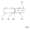
- the eccentric pin 64a engages in a curved elongated hole 66a of the sliding part 54a, which is aligned transversely to the longitudinal extension of the sliding part 54a or transverse to the horizontal longitudinal direction 56a, 58a ( Figure 4).
- the gear unit 22a is provided to transmit the rotational movement of the actuating means 20a in a clamping movement.
- the gear unit 22a has a cam mechanism unit formed with a integrally formed on the actuating means 20a, formed by a groove cam member 68a and on both sides in the base body 40a, formed by pins scanning members 70a, which engage in the cam member 68a forming groove and of which only one is shown.
- the scanning members 70a are arranged vertically offset in the vertical direction 60a and 62a in the base body 40a, so that a particularly short-built actuating means 20a and an advantageous scanning can be achieved.
- the seat mounting device has a band-shaped, in a side view substantially V-shaped spring element 36a made of a spring steel sheet separately formed by the sliding part 54a and by the vertical fastening means 14a, 16a, 18a, which is provided for the elastic deflection by the clamping movement.
- the spring element 36a is clamped with a free end via a screw not shown in the sliding part 54a has, after its chucking an angling about 130 ° and extending from its angled portion in the direction of the actuating means 20a.
- the spring element 36a serves as a cover element and forms a cover side of the seat attachment device.
- the seat attachment device has a lock display unit 38a and a rotational locking unit provided for securing the actuating means 20a in a rotational position associated with a locking position, both of which are partially made in one piece with the spring element 36a.
- the locking display unit 38a is essentially formed by a colored area 72a arranged on the base body 40a and a recess 74a of the spring element 36a which comes to rest above the area 72a when the seat fastening device is locked so that the colored area 72a can be seen through the recess 74a of the spring element 36a is ( Figures 1 and 2).
- the anti-rotation unit is essentially formed by a shape of the cam member 68a formed on the actuating means 20a or by a recess 76a, by the scanning member 70a and by the spring element 36a, which loads the actuating means 20a in a locking position in the direction of the scanning member 70a, so that the scanning member 70a is spring loaded in the recess 76a and an undesired release of the actuating means 20a is reliably avoided from a locking position ( Figure 2).
- the horizontal attachment means 10a, 12a engage positively in the passage openings 48a in the horizontal longitudinal direction 56a, 58a, so that the seat attachment device is fixed in a form-fitting manner via the horizontal attachment means 10a, 12a in the horizontal longitudinal direction 56a, 58a.
- the vertical attachment means 14a, 16a, 18a are passed through the passage openings 48a and the main body 40a comes with its bearing surface 78a, which runs parallel to the plane defined as a horizontal plane 30a of the seat attachment device, on the upper side of the mounting rail 42a to the system ( Figure 3).
- the actuating means 20a has on its cover side or on the vertical fastening means 14a, 16a, 18a side facing away from a hexagon socket over which the actuating means 20a are then rotated by a hexagon wrench 80a by approximately 210 ° counterclockwise from its unlocked position into its locking position can ( Figures 3 and 2).
- the slot 66a describes in its end to the edge of the sliding part 54a towards an outwardly forced circular path, so that by means of a rotation of 210 °, a desired longitudinal displacement is achieved ( Figure 4).
- By end stops formed by the cam member 68a it is ensured that the actuating means 20a can be rotated by a maximum of 210 °.
- the spring element 36a has at its end facing the actuating means 20a a recess 82a through which the hexagonal wrench 80a can be guided for actuating the actuating means 20a.
- the spring element 36a terminates flush with a cover side of the main body 40a and comes with its recess 74a above the color-coded area 72a to lie.
- a built-up by the deflection of the spring element 36a clamping force is transmitted from the spring member 36a on the sliding part 54a, so that this is moved together with the vertical attachment means 14a, 16a, 18a in the vertical direction 60a to the base body 40a and the vertical attachment means 14a, 16a, 18a with a clamping force on an underside of the profile edges 46a create the same.
- the seat attachment device is thus positively and non-positively fixed in the horizontal longitudinal direction 56a, 58a and in the vertical direction 60a, 62a. Due to the frictional connection, in particular relative movements of the seat fastening device for fastening rail 42a and a consequent noise development can be avoided.
- An unlocking of the seat mounting device is carried out accordingly in reverse order to lock.
- FIGS. 5 and 6 show a further exemplary embodiment of the invention. Substantially the same features and functions are always numbered with the same reference numerals. To distinguish the embodiments, the reference numerals the letters "a" and "b” added. The following description is essentially limited to the differences from the exemplary embodiment in FIGS. 1 to 4. With regard to features and functions that remain the same, reference may be made to the description of the exemplary embodiment in FIGS. 1 to 4.
- FIGS. 5 and 6 show a seat mounting device with an actuating means 20b, which has instead of a cam member formed by a groove 68a on a cover side, formed by a cam contour cam member 68b.
- cam member 68b acts a pivotally mounted, formed by a bending plate sensing member 70b together, which has at its free end an angled portion which rests with its end face on the cam contour.
- a sliding part 54b is displaced in the horizontal longitudinal direction 58b by means of an eccentric 34b (FIGS. 6 and 5) in accordance with the exemplary embodiment in FIGS.
- the scanning member 70b driven by the cam gear unit, pivoted in the vertical direction 60b, whereby a resting on an upper surface of the Abtastglieds 70b spring element 36b is deflected and tensioned without the actuating means 20b in its entirety a lifting movement in vertical direction 60b performs.
Abstract
Description
Die Erfindung geht aus von einer Sitzbefestigungsvorrichtung nach dem Oberbegriff des Anspruchs 1.The invention relates to a seat attachment device according to the preamble of claim 1.
Aus der
Der Erfindung liegt insbesondere die Aufgabe zugrunde, eine Sitzbefestigungsvorrichtung bereitzustellen, die eine kompakte Bauweise ermöglicht. Sie wird gemäß der Erfindung durch die Merkmale des Anspruchs 1 gelöst. Weitere Ausgestaltungen ergeben sich aus den Unteransprüchen.The invention is in particular the object of providing a seat mounting device that allows a compact design. It is achieved according to the invention by the features of claim 1. Further embodiments emerge from the subclaims.
Die Erfindung geht aus von einer Sitzbefestigungsvorrichtung, insbesondere zur Befestigung eines Sitzes an einem Boden eines Flugzeugs, mit wenigstens einem Horizontalbefestigungsmittel und wenigstens einem Vertikalbefestigungsmittel, das in eine Horizontallängsrichtung relativ zum Horizontalbefestigungsmittel verschiebbar ist, und mit einem drehbaren Betätigungsmittel sowie einer Getriebeeinheit zur Übertragung einer Drehbewegung des Betätigungsmittels in eine Verschiebebewegung des Vertikalbefestigungsmittels in Horizontallängsrichtung.The invention relates to a seat mounting device, in particular for fastening a seat to a floor of an aircraft, with at least one horizontal attachment means and at least one vertical attachment means which is displaceable in a horizontal longitudinal direction relative to the horizontal attachment means, and with a rotatable actuating means and a transmission unit for transmitting a rotational movement the actuating means in a sliding movement of the vertical fastening means in the horizontal direction.
Es wird vorgeschlagen, dass das Betätigungsmittel wenigstens eine Rotationsachse aufweist, die einen Winkel größer null zur Horizontallängsrichtung einschließt. Dabei soll unter einer "Horizontallängsrichtung" insbesondere eine zumindest im Wesentlichen parallel zu einer aufgespannten Bodenauflageebene der Sitzbefestigungsvorrichtung bzw. - in einer Einbaulage betrachtet - eine sich zu einer Hauptbodenebene eines Bodens, auf dem ein Sitz aufgeständert werden soll, erstreckende Richtung verstanden werden, die zudem in Längsrichtung der Sitzbefestigungsvorrichtung - und damit insbesondere in oder entgegen einer Sitzrichtung eines zu montierenden Sitzes - und in Längsrichtung einer auf dem Boden aufgebrachten Befestigungsschiene ausgerichtet ist. Unter "vertikal" soll insbesondere zumindest im Wesentlichen senkrecht auf einer von der Sitzbefestigungsvorrichtung aufgespannten Bodenauflageebene stehend bzw. auf der Hauptbodenebene des Bodens, auf dem ein Sitz aufgeständert werden soll, stehend verstanden werden. Unter dem Merkmal "größer null" soll insbesondere verstanden werden, dass die Ausrichtung der Rotationsachse gezielt von der Horizontallängsrichtung abweichend gewählt ist, so dass sich insbesondere eine über eine durch Toleranzen bedingte Winkelabweichung hinausgehende, vorzugsweise wesentliche Winkelabweichung einstellt.It is proposed that the actuating means has at least one axis of rotation which encloses an angle greater than zero to the horizontal longitudinal direction. In this case, under a "horizontal longitudinal direction" is in particular at least substantially parallel to a mounted floor support plane of the seat mounting device or - in an installation position - extending to a main floor level of a floor on which a seat is to be elevated, extending Direction are understood, which is also aligned in the longitudinal direction of the seat attachment device - and thus in particular in or against a seat direction of a seat to be mounted - and in the longitudinal direction of a mounted on the floor mounting rail. The term "vertical" should be understood to mean, in particular, standing vertically at least on a floor support plane spanned by the seat fastening device or standing on the main floor level of the floor on which a seat is to be raised. The term "greater than zero" is to be understood in particular to mean that the orientation of the axis of rotation is chosen to be different from the horizontal longitudinal direction, so that, in particular, an angle of deviation which exceeds tolerances is set, preferably a substantial angular deviation.
Mittels einer entsprechenden erfindungsgemäßen Ausgestaltung kann eine besonders kompakte und konstruktiv einfache Bauweise erreicht werden, und zwar insbesondere, indem das Betätigungsmittel besonders kurz und kompakt ausgeführt werden kann. Ferner kann eine komfortable Bedienbarkeit erzielt werden, und zwar insbesondere, wenn die Rotationsachse zu einer Horizontalebene der Sitzbefestigungsvorrichtung einen Winkel größer null einschließt und/oder die Rotationsachse des Betätigungsmittels einen Winkel größer 20°, vorzugsweise größer 45° und besonders bevorzugt größer 60° zur Horizontallängsrichtung und/oder besonders bevorzugt zur Horizontalebene einschließt. Unter einer "Horizontalebene" soll dabei insbesondere eine parallel zu einer von der Sitzbefestigungsvorrichtung aufgespannten Bodenauflageebene verlaufende Ebene verstanden werden.By means of a corresponding inventive design, a particularly compact and structurally simple construction can be achieved, in particular by the actuating means can be made very short and compact. Furthermore, a comfortable operability can be achieved, in particular if the axis of rotation to an horizontal plane of the seat mounting device includes an angle greater than zero and / or the axis of rotation of the actuating means an angle greater than 20 °, preferably greater than 45 ° and more preferably greater than 60 ° to the horizontal direction and / or particularly preferably to the horizontal plane. A "horizontal plane" is to be understood in particular as meaning a plane running parallel to a ground support plane spanned by the seat fastening device.
Die Drehbewegung des Betätigungsmittels kann durch verschiedene, dem Fachmann als sinnvoll erscheinende Getriebemittel in die Verschiebebewegung des Vertikalbefestigungsmittels übertragen werden, wie beispielsweise über ein Gewinde, eine Zahnstange, ein Zahnrad usw. Weist die Getriebeeinheit einen Exzenter auf, der zur Übertragung der Drehbewegung des Betätigungsmittels in die Verschiebebewegung des Vertikalbefestigungsmittels vorgesehen ist, kann besonders konstruktiv einfach mit einer kompakten Konstruktion die entsprechende Übertragung realisiert werden.The rotational movement of the actuating means can be transmitted by various, the skilled person appear appropriate gear in the sliding movement of the vertical attachment means, such as a thread, a rack, a gear, etc. Has the gear unit on an eccentric, which is used to transmit the rotational movement of the actuating means in the displacement movement of the vertical fastening means is provided, the corresponding transmission can be realized particularly simple in construction with a compact construction.
In einer weiteren Ausgestaltung der Erfindung wird vorgeschlagen, dass die Getriebeeinheit dazu vorgesehen ist, die Drehbewegung des Betätigungsmittels in eine Spannbewegung zu übertragen, wodurch zusätzliche Montage- und/oder Demontageschritte vermieden werden können und der Bedienkomfort erhöht werden kann. Dabei soll unter einer "Spannbewegung" sowohl eine Bewegung zur Reduzierung und insbesondere Aufhebung einer Spannkraft als auch eine Bewegung zur Erzeugung bzw. zur Erhöhung einer Spannkraft verstanden werden.In a further embodiment of the invention it is proposed that the gear unit is provided to transmit the rotational movement of the actuating means in a clamping movement, whereby additional assembly and / or disassembly steps can be avoided and the ease of use can be increased. In this case, a "tensioning movement" should be understood as meaning both a movement for reducing and, in particular, canceling out a tensioning force and a movement for generating or for increasing a tensioning force.
Weist die Getriebeeinheit eine Kurvengetriebeeinheit auf, um die Drehbewegung in die Spannbewegung zu übertragen, kann die Drehbewegung konstruktiv einfach und mit einer kompakten Bauweise entsprechend übertragen werden. Dabei soll unter einer "Kurvengetriebeeinheit" insbesondere eine Einheit verstanden werden, die ein eine Kurvenbahn bildendes Kurvenglied und ein mit der Kurvenbahn zur Korrespondenz vorgesehenes Abtastglied aufweist. Alternativ und/oder zusätzlich zu einer Kurvengetriebeeinheit sind jedoch auch andere, dem Fachmann als sinnvoll erscheinende Getriebeeinheiten denkbar, wie beispielsweise Zahnradgetriebeeinheiten, Hebelgetriebeeinheiten usw.If the gear unit has a cam gear unit in order to transmit the rotational movement into the tensioning movement, the rotational movement can be transmitted in a structurally simple manner and with a compact design. In this case, a "cam mechanism unit" should be understood to mean in particular a unit which has a cam member forming a cam track and a scanning member provided with the cam track for correspondence. Alternatively and / or in addition to a cam gear unit, however, others are also useful to the person skilled in the art appearing gear units conceivable, such as gear units, lever gear units, etc.
Die Kurvengetriebeeinheit kann dabei ein starres bzw. unbeweglich gelagertes Abtastglied aufweisen, so dass ein die Kurvenbahn aufweisendes Bauteil durch die Relativbewegung zwischen dem Abtastglied und dem Kurvenglied entsprechend in eine gewünschte Richtung angetrieben wird, oder die Kurvengetriebeeinheit kann ein bewegbar gelagertes Abtastglied aufweisen, wodurch der konstruktive Aufwand reduziert werden kann. Insbesondere kann vermieden werden, dass das Betätigungsmittel zusätzlich zu einer drehbaren Lagerung translatorisch verschiebbar gelagert werden muss.The cam gear unit may have a rigid or immovably mounted scanning member, so that a component having the cam track is driven by the relative movement between the scanning member and the cam member in a desired direction accordingly, or the cam gear unit may have a movably mounted scanning member, whereby the constructive Effort can be reduced. In particular, it can be avoided that the actuating means in addition to a rotatable mounting must be mounted translationally displaceable.
Sind der Exzenter und die Kurvengetriebeeinheit zumindest teilweise einstückig ausgebildet, können zusätzliche Bauteile, Bauraum, Gewicht, Montageaufwand und Kosten eingespart werden.If the eccentric and the cam gear unit are at least partially formed in one piece, additional components, space, weight, assembly costs and costs can be saved.
In einer weiteren Ausgestaltung der Erfindung wird vorgeschlagen, dass die Sitzbefestigungsvorrichtung wenigstens ein vom Vertikalbefestigungsmittel separat ausgebildetes Federelement aufweist, das zur elastischen Auslenkung durch die Spannbewegung vorgesehen ist. Unter "separat" soll dabei insbesondere verstanden werden, dass das Federelement und das Vertikalbefestigungsmittel zumindest aus unterschiedlichen Materialien hergestellt werden können, so dass insbesondere die Materialien vorteilhaft auf die Funktionen abgestimmt werden können.In a further embodiment of the invention, it is proposed that the seat fastening device has at least one spring element formed separately from the vertical fastening means, which is provided for the elastic deflection by the clamping movement. By "separate" is meant in particular that the spring element and the vertical attachment means can be made at least of different materials, so that in particular the materials can be advantageously adapted to the functions.
Ist das Federelement bandförmig ausgebildet, d.h. weist dasselbe im Vergleich zu seiner Länge und Breite eine relativ geringe Stärke auf, kann das Federelement Platz sparend integriert und vorteilhaft auch für weitere Funktionen genutzt werden. Ist das Federelement als Abdeckelement vorgesehen, können zusätzliche Abdeckelemente vermieden werden und es kann ein relativ großes Federelement ohne zumindest wesentliche Bauraumnachteile erreicht werden, mittels dessen ein vorteilhaft großer Federweg realisiert werden kann.If the spring element is band-shaped, i. has the same compared to its length and width on a relatively small thickness, the spring element can be integrated to save space and advantageously be used for other functions. If the spring element is provided as a covering element, additional covering elements can be avoided and a relatively large spring element can be achieved without at least substantial installation space disadvantages, by means of which an advantageously large spring travel can be realized.
Weist die Sitzbefestigungsvorrichtung eine Verriegelungsanzeigeeinheit auf und/oder weist die Sitzbefestigungsvorrichtung eine zur Sicherung des Betätigungsmittels in wenigstens einer Drehstellung vorgesehene Drehsicherungseinheit auf, kann eine gesteigerte Bediensicherheit erreicht werden.If the seat fastening device has a locking indicator unit and / or the seat fastening device has a rotational locking unit provided for securing the actuating means in at least one rotational position, an increased operating safety can be achieved.
Sind die Verriegelungsanzeigeeinheit und das Federelement, die Drehsicherungseinheit und das Federelement und/oder sind die Drehsicherungseinheit und der Exzenter zumindest teilweise einstückig ausgebildet, können wiederum zusätzliche Bauteile, Bauraum, Gewicht, Montageaufwand und Kosten eingespart werden.If the locking display unit and the spring element, the anti-rotation unit and the spring element and / or the anti-rotation unit and the eccentric are at least partially integral, in turn additional components, space, weight, assembly costs and costs can be saved.
Eine erfindungsgemäße Sitzbefestigungsvorrichtung eignet sich besonders vorteilhaft zur Befestigung eines Flugzeugsitzes in einem Flugzeug, ist jedoch auch in anderen, dem Fachmann als sinnvoll erscheinenden Bereichen einsetzbar, wie beispielsweise im Bereich von Fahrzeugen, wie größeren Personenwagen, Reisebussen, Schiffsfähren, oder im Rahmen einer Saalbestuhlung, wie für eine Kongresshalle, einen Theatersaal, einen Kinosaal usw. Ferner lässt sich die Sitzbefestigungsvorrichtung auch zum Festzurren von Lasten, Gepäck oder sonstigem Transportgut von Flug- und Fahrzeugen jedweder Art verwenden.A seat attachment device according to the invention is particularly advantageous for attaching an aircraft seat in an aircraft, but is also used in other, the expert appears reasonable areas, such as in the field of vehicles, such as larger passenger cars, coaches, ship ferries, or in the context of a room seating, as for a conference hall, a theater, a cinema hall, etc. Further, the seat attachment device can be Also for lashing loads, luggage or other cargo of aircraft and vehicles use of any kind.
Weitere Vorteile ergeben sich aus der folgenden Zeichnungsbeschreibung. In der Zeichnung sind Ausführungsbeispiele der Erfindung dargestellt. Die Zeichnung, die Beschreibung und die Ansprüche enthalten zahlreiche Merkmale in Kombination. Der Fachmann wird die Merkmale zweckmäßigerweise auch einzeln betrachten und zu sinnvollen weiteren Kombinationen zusammenfassen.Further advantages emerge from the following description of the drawing. In the drawings, embodiments of the invention are shown. The drawing, the description and the claims contain numerous features in combination. The person skilled in the art will expediently also consider the features individually and combine them into meaningful further combinations.
Es zeigen:
- Fig. 1
- eine Sitzbefestigungsvorrichtung schräg von oben im montierten Zustand an einer Befestigungsschiene,
- Fig. 2
- die Sitzbefestigungsvorrichtung aus Figur 1 in einem Teillängsschnitt in einer Verriegelungsstellung,
- Fig. 3
- die Sitzbefestigungsvorrichtung aus Figur 1 in einem Teillängsschnitt in einer Entriegelungsstellung,
- Fig. 4
- ein Einzelteil der Sitzbefestigungsvorrichtung in einer Draufsicht,
- Fig. 5
- eine alternative Sitzbefestigungsvorrichtung in einem Teillängsschnitt in einer Verriegelungsstellung und
- Fig. 6
- die Sitzbefestigungsvorrichtung aus Figur 5 in einer Entriegelungsstellung.
- Fig. 1
- a seat attachment device obliquely from above in the mounted state on a mounting rail,
- Fig. 2
- 1 shows the seat fastening device from FIG. 1 in a partial longitudinal section in a locking position,
- Fig. 3
- 1 shows the seat fastening device from FIG. 1 in a partial longitudinal section in an unlocking position,
- Fig. 4
- an item of the seat attachment device in a plan view,
- Fig. 5
- an alternative seat attachment device in a partial longitudinal section in a locking position and
- Fig. 6
- the seat attachment device of Figure 5 in an unlocked position.
Figur 1 zeigt eine Sitzbefestigungsvorrichtung zur Befestigung eines Sitzes an einem Boden 28a bzw. einem Kabinenboden eines Flugzeugs, und zwar an in Längsrichtung des Flugzeugs verlaufenden, an dem Kabinenboden befestigten und parallel zu demselben ausgerichteten Befestigungsschienen 42a. Die Befestigungsschienen 42a schließen mit ihrer Oberseite bündig mit dem Boden 28a bzw. Kabinenboden des Flugzeugs ab. Die Befestigungsschiene 42a wird von einem Hohlprofil gebildet, das an seiner Oberseite mit einander zugewandten Profilflanken 46a einen Längskanal 44a begrenzt. Der Längskanal 44a weist in einem vorgegebenen Maß seinen freien Eintrittsquerschnitt verbreiternde Durchtrittsöffnungen 48a auf, die voneinander einen gleichmäßigen Abstand aufweisen und bohrungsartig ausgeführt sind.FIG. 1 shows a seat fastening device for fastening a seat to a
Die Sitzbefestigungsvorrichtung weist einen Grundkörper 40a mit einem angeformten Lagerauge 50a zum Befestigen eines Sitzfußes 52a auf. Ferner sind an den Grundkörper 40a Horizontalbefestigungsmittel 10a, 12a einstückig angeformt, (Figuren 1 und 2). Die Horizontalbefestigungsmittel 10a, 12a erstrecken sich in vertikaler Richtung 62a über eine Auflagefläche 78a des Grundkörpers 40a hinaus, mittels der der Grundkörper 40a bei der Montage auf einer Oberseite der Befestigungsschiene 42a zum Liegen kommt und wobei die Auflagefläche 78a eine als Horizontalebene 30a definierte Ebene der Sitzbefestigungsvorrichtung aufspannt, die in der Einbaulage betrachtet zumindest im Wesentlichen parallel zum Boden 28a ausgerichtet ist. Ferner weisen die Horizontalbefestigungsmittel 10a, 12a quer zur Längserstreckung des Grundkörpers 40a beidseitig abstehende kreissegmentförmige Ausformungen auf.The seat attachment device has a
Zudem weist die Sitzbefestigungsvorrichtung ein relativ zum Grundkörper 40a in Horizontallängsrichtung 56a, 58a verschiebbares Schiebeteil 54a auf, an das in Längsrichtung der Sitzbefestigungsvorrichtung bzw. in Horizontallängsrichtung 56a, 58a zu den Horizontalbefestigungsmitteln 10a, 12a beabstandete Vertikalbefestigungsmittel 14a, 16a, 18a einstückig angeformt sind. Die Horizontallängsrichtung 56a, 58a erstreckt sich zumindest im Wesentlichen parallel zur Längsrichtung des Schiebeteils 54a sowie in der Einbaulage betrachtet zumindest im Wesentlichen parallel zur Befestigungsschiene 42a und damit zumindest im Wesentlichen parallel zum Boden 28a.In addition, the seat fastening device has a relative to the
Die Vertikalbefestigungsmittel 14a, 16a, 18a ragen in die von einer Deckseite der Sitzbefestigungsvorrichtung abgewandte vertikale Richtung 62a über die Horizontalbefestigungsmittel 10a, 12a hinaus und weisen quer zur Längserstreckung des Schiebeteils 54a beidseitig abstehende kreissegmentförmige Ausformungen auf.The vertical fastening means 14a, 16a, 18a project beyond the horizontal fastening means 10a, 12a in the
Ferner weist die Sitzbefestigungsvorrichtung ein in einer Ausnehmung des Grundkörpers 40a drehbar gelagertes und durch den Grundkörper 40a in seiner Drehbewegung geführtes Betätigungsmittel 20a sowie eine Getriebeeinheit 22a zur Übertragung einer Drehbewegung des Betätigungsmittels 20a in eine Verschiebebewegung des Schiebeteils 54a mit den Vertikalbefestigungsmitteln 14a, 16a, 18a in Horizontallängsrichtung 56a, 58a auf.Furthermore, the seat mounting device has a in a recess of the
Das Betätigungsmittel 20a weist eine Rotationsachse 24a auf, die einen Winkel 26a von ca. 90° zur Horizontallängsrichtung 56a, 58a und einen Winkel 32a von ca. 90° zur Horizontalebene 30a der Sitzbefestigungsvorrichtung einschließt bzw. ist die Rotationsachse 24a zumindest im Wesentlichen senkrecht zur Horizontalebene 30a der Sitzbefestigungsvorrichtung sowie in der Einbaulage betrachtet zumindest im Wesentlichen senkrecht zum Boden 28a ausgerichtet.The actuating means 20a has a
Die Getriebeeinheit 22a weist einen teilweise einstückig mit dem Betätigungsmittel 20a ausgebildeten Exzenter 34a auf, der zur Übertragung der Drehbewegung des Betätigungsmittels 20a in die Verschiebebewegung in Horizontallängsrichtung 56a, 58a des Schiebeteils 54a mit den Vertikalbefestigungsmitteln 14a, 16a, 18a vorgesehen ist. Der Exzenter 34a weist dabei einen Exzenterzapfen 64a auf, der auf einer Unterseite des Betätigungsmittels 20a in dasselbe radial zur Rotationsachse 24a beabstandet bzw. exzentrisch eingeschraubt ist. Der Exzenterzapfen 64a greift in ein gekrümmtes Langloch 66a des Schiebeteils 54a, das quer zur Längserstreckung des Schiebeteils 54a bzw. quer zur Horizontallängsrichtung 56a, 58a ausgerichtet ist (Figur 4).The
Ferner ist die Getriebeeinheit 22a dazu vorgesehen, die Drehbewegung des Betätigungsmittels 20a in eine Spannbewegung zu übertragen. Hierfür weist die Getriebeeinheit 22a eine Kurvengetriebeeinheit mit einem einstückig an das Betätigungsmittel 20a angeformten, von einer Nut gebildeten Kurvenglied 68a und beidseitig im Grundkörper 40a befestigten, von Stiften gebildeten Abtastgliedern 70a auf, die in die das Kurvenglied 68a bildende Nut eingreifen und von denen nur eines dargestellt ist. Die Abtastglieder 70a sind in vertikaler Richtung 60a bzw. 62a geringfügig höhenversetzt im Grundkörper 40a angeordnet, so dass ein besonders kurz bauendes Betätigungsmittel 20a und eine vorteilhafte Abtastung erreicht werden können.Further, the
Die Sitzbefestigungsvorrichtung weist ein vom Schiebeteil 54a und von den Vertikalbefestigungsmitteln 14a, 16a, 18a separat ausgebildetes, bandförmiges, in einer Seitenansicht im Wesentlichen V-förmiges Federelement 36a aus einem Federstahlblech auf, das zur elastischen Auslenkung durch die Spannbewegung vorgesehen ist. Das Federelement 36a ist mit einem freien Ende über eine nicht näher dargestellte Schraubverbindung in das Schiebeteil 54a eingespannt, weist nach seinem Einspannbereich eine Abwinklung um ca. 130° auf und erstreckt sich ausgehend von seiner Abwinklung in Richtung des Betätigungsmittels 20a. Das Federelement 36a dient als Abdeckelement und bildet eine Deckseite der Sitzbefestigungsvorrichtung.The seat mounting device has a band-shaped, in a side view substantially V-shaped
Ferner weist die Sitzbefestigungsvorrichtung eine Verriegelungsanzeigeeinheit 38a und eine zur Sicherung des Betätigungsmittels 20a in einer einer Verriegelungsstellung zugeordneten Drehstellung vorgesehene Drehsicherungseinheit auf, die beide teilweise einstückig mit dem Federelement 36a ausgeführt sind.Furthermore, the seat attachment device has a
Die Verriegelungsanzeigeeinheit 38a wird im Wesentlichen durch einen am Grundkörper 40a angeordneten farbigen Bereich 72a und eine Ausnehmung 74a des Federelements 36a gebildet, die bei verriegelter Sitzbefestigungsvorrichtung über dem Bereich 72a zum Liegen kommt, so dass der farbige Bereich 72a durch die Ausnehmung 74a des Federelements 36a erkennbar ist (Figuren 1 und 2).The locking
Die Drehsicherungseinheit wird im Wesentlichen von einer Ausformung des an das Betätigungsmittel 20a angeformten Kurvenglieds 68a bzw. von einer Einbuchtung 76a, von dem Abtastglied 70a und von dem Federelement 36a gebildet, das das Betätigungsmittel 20a in einer Verriegelungsstellung in Richtung des Abtastglieds 70a belastet, so dass das Abtastglied 70a federbelastet in der Einbuchtung 76a angeordnet ist und ein unerwünschtes Lösen des Betätigungsmittels 20a aus einer Verriegelungsstellung sicher vermieden ist (Figur 2).The anti-rotation unit is essentially formed by a shape of the
Bei der Montage wird die Sitzbefestigungsvorrichtung auf die Befestigungsschiene 42a aufgesetzt. Dabei greifen die Horizontalbefestigungsmittel 10a, 12a in Horizontallängsrichtung 56a, 58a formschlüssig in die Durchtrittsöffnungen 48a ein, so dass die Sitzbefestigungsvorrichtung über die Horizontalbefestigungsmittel 10a, 12a in Horizontallängsrichtung 56a, 58a formschlüssig fixiert ist. Die Vertikalbefestigungsmittel 14a, 16a, 18a werden durch die Durchtrittsöffnungen 48a hindurchgeführt und der Grundkörper 40a kommt mit seiner Auflagefläche 78a, die parallel zu der als Horizontalebene 30a definierten Ebene der Sitzbefestigungsvorrichtung verläuft, auf der Oberseite der Befestigungsschiene 42a zur Anlage (Figur 3).When mounting the seat attachment device is placed on the mounting
Das Betätigungsmittel 20a weist an seiner Deckseite bzw. auf der den Vertikalbefestigungsmitteln 14a, 16a, 18a abgewandten Seite einen Innensechskant auf, über den das Betätigungsmittel 20a anschließend mit einem Sechskantschlüssel 80a um ca. 210° entgegen dem Uhrzeigersinn von seiner Entriegelungsstellung in seine Verriegelungsstellung gedreht werden kann (Figuren 3 und 2). Das Langloch 66a beschreibt in seinem Endverlauf zum Rand des Schiebeteils 54a hin eine nach außen gezwungene Kreisbahn, so dass mittels einer Umdrehung von 210° eine gewünschte Längsverschiebung erreicht wird (Figur 4). Durch vom Kurvenglied 68a gebildete Endanschläge wird sichergestellt, dass das Betätigungsmittel 20a maximal um 210° gedreht werden kann. Das Federelement 36a weist an seinem dem Betätigungsmittel 20a zugewandten Ende eine Ausnehmung 82a auf, durch die der Sechskantschlüssel 80a zum Betätigen des Betätigungsmittels 20a geführt werden kann.The actuating means 20a has on its cover side or on the vertical fastening means 14a, 16a, 18a side facing away from a hexagon socket over which the actuating means 20a are then rotated by a
Durch die Drehbewegung des Betätigungsmittels 20a wird das Schiebeteil 54a gemeinsam mit den Vertikalbefestigungsmitteln 14a, 16a, 18a, angetrieben mittels des Exzenters 34a, in Horizontallängsrichtung 58a um 12,7 mm verschoben, so dass die Vertikalbefestigungsmittel 14a, 16a, 18a unterhalb der Profilflanken 46a zum Liegen kommen.As a result of the rotational movement of the actuating means 20a, the sliding
Ferner wird durch die Drehbewegung des Betätigungsmittels 20a dasselbe, angetrieben mittels der Kurvengetriebeeinheit, in vertikaler Richtung 60a verfahren, wodurch das auf einer Oberseite des Betätigungsmittels 20a aufliegende Federelement 36a ausgelenkt und gespannt wird. Der Exzenterzapfen 64a ist entsprechend lang ausgeführt, so dass dieser stets in das Langloch 66a eingreift.Further, by the rotational movement of the actuating means 20a, the same, driven by means of the cam gear unit, moved in the
Im gespannten Zustand schließt das Federelement 36a bündig mit einer Deckseite des Grundkörpers 40a ab und kommt mit seiner Ausnehmung 74a über dem farblich markierten Bereich 72a zum Liegen. Eine durch die Auslenkung des Federelements 36a sich aufbauende Spannkraft wird vom Federelement 36a auf das Schiebeteil 54a übertragen, so dass dieses gemeinsam mit den Vertikalbefestigungsmitteln 14a, 16a, 18a in vertikaler Richtung 60a zum Grundkörper 40a bewegt wird und sich die Vertikalbefestigungsmittel 14a, 16a, 18a mit einer Spannkraft an einer Unterseite der Profilflanken 46a an denselben anlegen. Die Sitzbefestigungsvorrichtung ist damit in Horizontallängsrichtung 56a, 58a und in vertikaler Richtung 60a, 62a form- und kraftschlüssig fixiert. Durch den Kraftschluss können insbesondere Relativbewegungen der Sitzbefestigungsvorrichtung zur Befestigungsschiene 42a und eine dadurch bedingte Geräuschentwicklung vermieden werden.In the tensioned state, the
Eine Entriegelung der Sitzbefestigungsvorrichtung erfolgt entsprechend in umgekehrter Reihenfolge zur Verriegelung.An unlocking of the seat mounting device is carried out accordingly in reverse order to lock.
In den Figuren 5 und 6 ist ein weiteres Ausführungsbeispiel der Erfindung dargestellt. Im Wesentlichen gleich bleibende Merkmale und Funktionen sind grundsätzlich mit den gleichen Bezugszeichen beziffert. Zur Unterscheidung der Ausführungsbeispiele sind den Bezugszeichen die Buchstaben "a" und "b" hinzugeführt. Die nachfolgende Beschreibung beschränkt sich im Wesentlichen auf die Unterschiede zum Ausführungsbeispiel in den Figuren 1 bis 4. Bezüglich gleich bleibender Merkmale und Funktionen darf auf die Beschreibung zu dem Ausführungsbeispiel in den Figuren 1 bis 4 verwiesen werden.FIGS. 5 and 6 show a further exemplary embodiment of the invention. Substantially the same features and functions are always numbered with the same reference numerals. To distinguish the embodiments, the reference numerals the letters "a" and "b" added. The following description is essentially limited to the differences from the exemplary embodiment in FIGS. 1 to 4. With regard to features and functions that remain the same, reference may be made to the description of the exemplary embodiment in FIGS. 1 to 4.
Die Figuren 5 und 6 zeigen eine Sitzbefestigungsvorrichtung mit einem Betätigungsmittel 20b, das anstatt eines von einer Nut gebildeten Kurvenglieds 68a ein an einer Deckseite angeordnetes, von einer Nockenkontur gebildetes Kurvenglied 68b aufweist. Mit dem Kurvenglied 68b wirkt ein schwenkbar gelagertes, von einem Biegeblech gebildetes Abtastglied 70b zusammen, das an seinem freien Ende eine Abwinklung aufweist, die mit ihrer Stirnseite auf der Nockenkontur aufliegt. Wird das Betätigungsmittel 20b gedreht wird entsprechend dem Ausführungsbeispiel in den Figuren 1 bis 4 ein Schiebeteil 54b in Horizontallängsrichtung 58b mittels eines Exzenters 34b verschoben (Figuren 6 und 5). Ferner wird durch die Drehbewegung des Betätigungsmittels 20b das Abtastglied 70b, angetrieben mittels der Kurvengetriebeeinheit, in vertikaler Richtung 60b geschwenkt, wodurch ein auf einer Oberseite des Abtastglieds 70b aufliegendes Federelement 36b ausgelenkt und gespannt wird, ohne dass das Betätigungsmittel 20b in seiner Gesamtheit eine Hubbewegung in vertikaler Richtung 60b durchführt.Figures 5 and 6 show a seat mounting device with an actuating means 20b, which has instead of a cam member formed by a
- 1010
- HorizontalbefestigungsmittelHorizontal fasteners
- 1212
- HorizontalbefestigungsmittelHorizontal fasteners
- 1414
- VertikalbefestigungsmittelVertical fasteners
- 1616
- VertikalbefestigungsmittelVertical fasteners
- 1818
- VertikalbefestigungsmittelVertical fasteners
- 2020
- Betätigungsmittelactuating means
- 2222
- Getriebeeinheitgear unit
- 2424
- Rotationsachseaxis of rotation
- 2626
- Winkelangle
- 2828
- Bodenground
- 3030
- HorizontalebeneWL
- 3232
- Winkelangle
- 3434
- Exzentereccentric
- 3636
- Federelementspring element
- 3838
- VerriegelungsanzeigeeinheitLock display unit
- 4040
- Grundkörperbody
- 4242
- Befestigungsschienemounting rail
- 4444
- Längskanallongitudinal channel
- 4646
- Profilflankeflank
- 4848
- DurchtrittsöffnungThrough opening
- 5050
- Lageraugebearing eye
- 5252
- Sitzfußseat foot
- 5454
- Schiebeteilsliding part
- 5656
- HorizontallängsrichtungHorizontal longitudinal direction
- 5858
- HorizontallängsrichtungHorizontal longitudinal direction
- 6060
- Richtungdirection
- 6262
- Richtungdirection
- 6464
- Exzenterzapfeneccentric
- 6666
- LanglochLong hole
- 6868
- Kurvengliedcam member
- 7070
- Abtastgliedscanning element
- 7272
- BereichArea
- 7474
- Ausnehmungrecess
- 7676
- Einbuchtungindentation
- 7878
- Auflageflächebearing surface
- 8080
- SechskantschlüsselAllen key
- 8282
- Ausnehmungrecess
Claims (17)
dadurch gekennzeichnet,
dass das Betätigungsmittel (20) wenigstens eine Rotationsachse (24) aufweist, die einen Winkel (26) größer null zur Horizontallängsrichtung (56, 58) einschließt.Seat fastening device, in particular for fastening a seat to a floor (28) of an aircraft, having at least one horizontal fastening means (10, 12) and at least one vertical fastening means (14, 16, 18) arranged in a horizontal longitudinal direction (56, 58) relative to the horizontal fastening means ( 10, 12) is displaceable, and with a rotatable actuating means (20) and a transmission unit (22) for transmitting a rotational movement of the actuating means (20) in a sliding movement of the vertical fastening means (14, 16, 18) in the horizontal longitudinal direction (56, 58),
characterized,
in that the actuating means (20) has at least one axis of rotation (24) which encloses an angle (26) greater than zero to the horizontal longitudinal direction (56, 58).
dadurch gekennzeichnet,
dass die Rotationsachse (24) zu einer Horizontalebene (30) einen Winkel (32) größer null einschließt.Seat fixing device according to claim 1,
characterized,
in that the axis of rotation (24) encloses an angle (32) greater than zero with respect to a horizontal plane (30).
dadurch gekennzeichnet,
dass die Rotationsachse (24) des Betätigungsmittels (20) einen Winkel (26) größer 20° zur Horizontallängsrichtung (56, 58) einschließt.Seat fixing device according to claim 1 or 2,
characterized,
that the axis of rotation (24) of the actuating means (20) includes an angle (26) greater than 20 ° to the horizontal longitudinal direction (56, 58).
dadurch gekennzeichnet,
dass die Rotationsachse (24) des Betätigungsmittels (20) einen Winkel (32) größer 20° zur Horizontalebene (30) einschließt.Seat fixing device according to claim 2 and 3,
characterized,
that the axis of rotation (24) of the actuating means (20) includes an angle (32) greater than 20 ° to the horizontal plane (30).
dadurch gekennzeichnet,
dass die Getriebeeinheit (22) einen Exzenter (34) aufweist, der zur Übertragung der Drehbewegung des Betätigungsmittels (20) in die Verschiebebewegung in Horizontallängsrichtung (56, 58) des Vertikalbefestigungsmittels (14, 16, 18) vorgesehen ist.Seat fixing device according to one of the preceding claims,
characterized,
in that the gear unit (22) has an eccentric (34) which is provided for transmitting the rotational movement of the actuating means (20) into the displacement movement in the horizontal longitudinal direction (56, 58) of the vertical fastening means (14, 16, 18).
dadurch gekennzeichnet,
dass die Getriebeeinheit (22) dazu vorgesehen ist, die Drehbewegung des Betätigungsmittels (20) in eine Spannbewegung zu übertragen.Seat fixing device according to one of the preceding claims,
characterized,
in that the gear unit (22) is provided for transmitting the rotational movement of the actuating means (20) into a tensioning movement.
dadurch gekennzeichnet,
dass die Getriebeeinheit (22) eine Kurvengetriebeeinheit aufweist, um die Drehbewegung in die Spannbewegung zu übertragen.Seat fixing device according to claim 6,
characterized,
in that the gear unit (22) has a cam gear unit in order to transmit the rotational movement into the clamping movement.
dadurch gekennzeichnet,
dass die Kurvengetriebeeinheit der Getriebeeinheit (22b) ein beweglich gelagertes Abtastglied (70b) aufweist.Seat fixing device according to claim 7,
characterized,
that the cam mechanism unit of the transmission unit (22b) comprises a movably mounted scanning element (70b).
dadurch gekennzeichnet,
dass der Exzenter (34) und die Kurvengetriebeeinheit zumindest teilweise einstückig ausgebildet sind.Seat fixing device at least according to claim 5 and 7,
characterized,
that the eccentric (34) and the cam gear unit are at least partially formed in one piece.
gekennzeichnet durch
wenigstens ein vom Vertikalbefestigungsmittel (14, 16, 18) separat ausgebildetes Federelement (36), das zur elastischen Auslenkung durch die Spannbewegung vorgesehen ist.Seat fixing device at least according to claim 6,
marked by
at least one of the vertical fastening means (14, 16, 18) separately formed spring element (36) which is provided for elastic deflection by the clamping movement.
dadurch gekennzeichnet,
dass das Federelement (36) bandförmig ausgebildet ist.Seat fixing device according to claim 10,
characterized,
that the spring element (36) is strip-shaped.
dadurch gekennzeichnet,
dass das Federelement (36) als Abdeckelement vorgesehen ist.Seat fixing device at least according to claim 10,
characterized,
that the spring element (36) is provided as a cover.
gekennzeichnet durch
eine Verriegelungsanzeigeeinheit (38).Seat fixing device according to one of the preceding claims,
marked by
a lock display unit (38).
dadurch gekennzeichnet,
dass die Verriegelungsanzeigeeinheit (38) und das Federelement (36) zumindest teilweise einstückig ausgebildet sind.Seat fixing device at least according to claim 10 and 13,
characterized,
that the locking indication unit (38) and the spring element (36) are at least partially formed integrally.
gekennzeichnet durch
eine Drehsicherungseinheit, die zur Sicherung des Betätigungsmittels (20a) in wenigstens einer Drehstellung vorgesehen ist.Seat fixing device according to one of the preceding claims,
marked by
a rotation lock unit, which is provided for securing the actuating means (20a) in at least one rotational position.
dadurch gekennzeichnet,
dass die Drehsicherungseinheit und das Federelement (36a) zumindest teilweise einstückig ausgebildet sind.Seat fixing device at least according to claim 10 and 15,
characterized,
in that the anti-rotation unit and the spring element (36a) are formed at least partially in one piece.
dadurch gekennzeichnet,
dass die Drehsicherungseinheit und der Exzenter (34a) zumindest teilweise einstückig ausgebildet sind.Seat fixing device at least according to claim 5 and 15,
characterized,
in that the anti-rotation unit and the eccentric (34a) are formed at least partially in one piece.
Applications Claiming Priority (1)
| Application Number | Priority Date | Filing Date | Title |
|---|---|---|---|
| DE102005049187A DE102005049187A1 (en) | 2005-10-14 | 2005-10-14 | Seat fastening device |
Publications (3)
| Publication Number | Publication Date |
|---|---|
| EP1775217A2 true EP1775217A2 (en) | 2007-04-18 |
| EP1775217A3 EP1775217A3 (en) | 2008-02-27 |
| EP1775217B1 EP1775217B1 (en) | 2010-01-13 |
Family
ID=37591855
Family Applications (1)
| Application Number | Title | Priority Date | Filing Date |
|---|---|---|---|
| EP06015643A Not-in-force EP1775217B1 (en) | 2005-10-14 | 2006-07-27 | Seat attachment device |
Country Status (4)
| Country | Link |
|---|---|
| US (1) | US7661637B2 (en) |
| EP (1) | EP1775217B1 (en) |
| AT (1) | ATE455037T1 (en) |
| DE (2) | DE102005049187A1 (en) |
Cited By (2)
| Publication number | Priority date | Publication date | Assignee | Title |
|---|---|---|---|---|
| DE102009014722A1 (en) * | 2009-03-27 | 2010-09-30 | Recaro Aircraft Seating Gmbh & Co. Kg | Fixing device for fixing an aircraft seat to a fixing rail comprises an actuating unit and a vibration damping unit coaxially arranged in relation to the axis of rotation |
| WO2014161764A1 (en) * | 2013-04-05 | 2014-10-09 | Recaro Aircraft Seating Gmbh & Co. Kg | Seat mount |
Families Citing this family (29)
| Publication number | Priority date | Publication date | Assignee | Title |
|---|---|---|---|---|
| DE102008048745B4 (en) * | 2008-09-24 | 2014-01-02 | Airbus Operations Gmbh | Locking device for a lockable on a rail object, use of such a locking device and means of transport with such a device |
| DE102008062466A1 (en) * | 2008-12-17 | 2010-08-26 | Airbus Deutschland Gmbh | Device for fastening an object to a rail |
| FR2947773B1 (en) * | 2009-07-09 | 2012-01-06 | Attax | SYSTEM FOR ATTACHING A SEAT, FOR EXAMPLE OF AN AIRCRAFT |
| FR2959985B1 (en) * | 2010-05-17 | 2013-02-22 | Attax | SYSTEM FOR ATTACHING AN AIRCRAFT SEAT IN A FASTENING RAIL |
| DE102012205467A1 (en) * | 2012-04-03 | 2013-10-10 | Airbus Operations Gmbh | Device for mounting clamping device in profiled rail to fasten seat in passenger cabin e.g. airplane cabin, has driver brought in engagement with clamping element in form-fit manner, and holding element placing tool for actuation of driver |
| DE102013000728A1 (en) | 2013-01-17 | 2014-03-13 | Daimler Ag | Device for releasably fastening mounting components e.g. passenger seat in interior of e.g. bus, has actuator system of holding portion that is moved from one unlocked position to another locked position |
| DE102014201176A1 (en) * | 2014-01-23 | 2015-07-23 | Bishop Gmbh | Aircraft seat fitting |
| DE102016110057A1 (en) * | 2016-05-31 | 2017-11-30 | Airbus Operations Gmbh | Passenger seating system for a cabin of a means of transport |
| US11358497B2 (en) | 2018-05-04 | 2022-06-14 | Lear Corporation | Track system having a rolling member |
| US10882420B2 (en) | 2019-03-08 | 2021-01-05 | Lear Corporation | Track assembly |
| US10906431B2 (en) | 2018-05-04 | 2021-02-02 | Lear Corporation | Track assembly |
| US10926667B2 (en) | 2018-05-04 | 2021-02-23 | Lear Corporation | Track assembly |
| US11040639B2 (en) | 2018-05-04 | 2021-06-22 | Lear Corporation | Track assembly |
| US10562414B2 (en) | 2018-05-04 | 2020-02-18 | Lear Corporation | Track assembly |
| US11040638B2 (en) | 2018-05-04 | 2021-06-22 | Lear Corporation | Track assembly |
| US11225201B2 (en) | 2018-12-10 | 2022-01-18 | Lear Corporation | Track assembly |
| US11440482B2 (en) | 2018-12-10 | 2022-09-13 | Lear Corporation | Track assembly |
| US11117538B2 (en) | 2018-12-17 | 2021-09-14 | Lear Corporation | Electrical assembly |
| US11613220B2 (en) | 2018-12-17 | 2023-03-28 | Lear Corporation | Electrical assembly |
| US10855037B2 (en) | 2018-12-17 | 2020-12-01 | Lear Corporation | Support assembly with a support member and a track assembly |
| US10950977B2 (en) | 2018-12-18 | 2021-03-16 | Lear Corporation | Track assembly for a vehicle component |
| US11040653B2 (en) | 2019-02-25 | 2021-06-22 | Lear Corporation | Track assembly |
| US11807142B2 (en) | 2019-03-06 | 2023-11-07 | Lear Corporation | Electrical track assembly |
| US11299075B2 (en) | 2019-03-06 | 2022-04-12 | Lear Corporation | Electrical assembly |
| US11634101B2 (en) | 2019-10-04 | 2023-04-25 | Lear Corporation | Removable component system |
| US11323114B2 (en) | 2019-10-04 | 2022-05-03 | Lear Corporation | Electrical system |
| US11463083B2 (en) | 2019-10-04 | 2022-10-04 | Lear Corporation | Electrical system |
| US20210261022A1 (en) | 2020-02-21 | 2021-08-26 | Lear Corporation | Track system with a support member |
| US11505141B2 (en) | 2020-10-23 | 2022-11-22 | Lear Corporation | Electrical system with track assembly and support assembly |
Citations (1)
| Publication number | Priority date | Publication date | Assignee | Title |
|---|---|---|---|---|
| GB2406877A (en) | 2003-10-11 | 2005-04-13 | Unwin C N Ltd | Device for temporary connection of movable object to a track |
Family Cites Families (16)
| Publication number | Priority date | Publication date | Assignee | Title |
|---|---|---|---|---|
| DE2552761A1 (en) * | 1975-11-25 | 1977-05-26 | Keiper Kg | LONGITUDINAL SLIDING AND LOCAL POSITIONS LOCKABLE, ESPECIALLY TO BE ARRANGED IN VEHICLES SUCH AS MOTOR VEHICLES |
| US4047689A (en) * | 1976-07-19 | 1977-09-13 | Uop Inc. | Load distributing track fitting |
| US4062298A (en) * | 1976-11-10 | 1977-12-13 | Uop Inc. | Anti rattle track fitting |
| US4376522A (en) * | 1981-05-18 | 1983-03-15 | Kidde, Inc. | Aircraft seat |
| US4496271A (en) * | 1982-09-30 | 1985-01-29 | East/West Industries, Inc. | Restraining fittings |
| US4708549A (en) * | 1986-05-01 | 1987-11-24 | Ancra Corporation | Rattle-proof anchor fitting for securing loads to retainer track |
| US4796837A (en) * | 1987-07-27 | 1989-01-10 | Dowd Eugene G | Leg seat track fitting with improved bearing member |
| US4771969A (en) * | 1987-07-27 | 1988-09-20 | Sabre Industries, Inc. | Leg set track fitting |
| US5083726A (en) * | 1989-05-10 | 1992-01-28 | Sabre Industries, Inc. | Seat track bearing for an airplane |
| GB9013717D0 (en) | 1990-06-20 | 1990-08-08 | Rumbold Ltd L A | Adjustable passenger seating arrangement |
| EP0583295B1 (en) | 1991-04-27 | 1994-11-23 | MICHLER, Walter | Quick-release fastening device |
| DE19520959C2 (en) * | 1995-06-08 | 2000-08-17 | Albert Muehlenberg Apparatebau | Quick change fitting |
| US5871318A (en) * | 1997-11-12 | 1999-02-16 | Be Aerospace, Inc. | Quick-release track fastener |
| DE19937652A1 (en) * | 1999-08-12 | 2001-02-15 | Hammerstein Gmbh C Rob | Actuating device for locking a vehicle seat |
| DE10341624A1 (en) * | 2003-09-10 | 2005-04-07 | Recaro Aircraft Seating Gmbh & Co. Kg | Seat attachment system |
| US6902365B1 (en) * | 2004-02-13 | 2005-06-07 | B E Aerospace, Inc. | Quick-release track fastener |
-
2005
- 2005-10-14 DE DE102005049187A patent/DE102005049187A1/en not_active Withdrawn
- 2005-12-06 US US11/294,340 patent/US7661637B2/en not_active Expired - Fee Related
-
2006
- 2006-07-27 EP EP06015643A patent/EP1775217B1/en not_active Not-in-force
- 2006-07-27 DE DE502006005898T patent/DE502006005898D1/en active Active
- 2006-07-27 AT AT06015643T patent/ATE455037T1/en active
Patent Citations (1)
| Publication number | Priority date | Publication date | Assignee | Title |
|---|---|---|---|---|
| GB2406877A (en) | 2003-10-11 | 2005-04-13 | Unwin C N Ltd | Device for temporary connection of movable object to a track |
Cited By (4)
| Publication number | Priority date | Publication date | Assignee | Title |
|---|---|---|---|---|
| DE102009014722A1 (en) * | 2009-03-27 | 2010-09-30 | Recaro Aircraft Seating Gmbh & Co. Kg | Fixing device for fixing an aircraft seat to a fixing rail comprises an actuating unit and a vibration damping unit coaxially arranged in relation to the axis of rotation |
| DE102009014722B4 (en) * | 2009-03-27 | 2016-06-23 | Recaro Aircraft Seating Gmbh & Co. Kg | Seat fastening device |
| WO2014161764A1 (en) * | 2013-04-05 | 2014-10-09 | Recaro Aircraft Seating Gmbh & Co. Kg | Seat mount |
| US9669934B2 (en) | 2013-04-05 | 2017-06-06 | Recaro Aircraft Seating Gmbh & Co. Kg | Seat fastening |
Also Published As
| Publication number | Publication date |
|---|---|
| DE102005049187A1 (en) | 2007-04-19 |
| ATE455037T1 (en) | 2010-01-15 |
| DE502006005898D1 (en) | 2010-03-04 |
| US7661637B2 (en) | 2010-02-16 |
| US20070090261A1 (en) | 2007-04-26 |
| EP1775217B1 (en) | 2010-01-13 |
| EP1775217A3 (en) | 2008-02-27 |
Similar Documents
| Publication | Publication Date | Title |
|---|---|---|
| EP1775217B1 (en) | Seat attachment device | |
| EP1794052B1 (en) | Seat fixing device | |
| EP1792827B1 (en) | Seat attachment device | |
| EP1663780B1 (en) | Seat securing system | |
| DE60315734T2 (en) | IMPROVED FLOOR INSTALLED ON THE FLOOR PANEL OF A VEHICLE FOR FIXING CHAIRS, ARMCHAIRS AND WHEELCHAIRS | |
| EP2142428B1 (en) | Device for the fixation of objects | |
| EP2686212B1 (en) | Height adjuster for a fastening fitting of a safety belt system | |
| EP0583295A1 (en) | Quick-release fastening device. | |
| DE19654395C1 (en) | Cam for releasable locking of vehicle seat | |
| EP1180452A2 (en) | Fixing device for rigid suitcases in a load compartment of a vehicle | |
| WO2014161764A1 (en) | Seat mount | |
| DE102012020032A1 (en) | Seat support device for use in aircraft, has reinforcing outer profile for enclosing support section in mounted state, and bearing unit arranged between support section and reinforcing outer profile in mounted state | |
| DE19812490A1 (en) | Device for detachable attachment of motor vehicle seat on longitudinally extending rail | |
| DE10206780A1 (en) | Fastening device for a child seat | |
| DE3447178A1 (en) | Aircraft passenger seat | |
| EP1162112B1 (en) | Anchor for fixing of a load on a support plate | |
| DE102013107083B4 (en) | Device for fixing an object | |
| EP0825050B1 (en) | Stanchion between an upper boom and the platform frame of a vehicle | |
| EP1264744A2 (en) | Safety belt fastening arrangement | |
| DE102010031202B4 (en) | Seat base for a motor vehicle | |
| DE3029127A1 (en) | LEADING ADJUSTING RAIL | |
| DE10255446B4 (en) | protection mat | |
| EP0771689B1 (en) | Locking device for a vehicle seat | |
| WO2002018735A1 (en) | Door fastening | |
| DE102013111408B3 (en) | Stowage |
Legal Events
| Date | Code | Title | Description |
|---|---|---|---|
| PUAI | Public reference made under article 153(3) epc to a published international application that has entered the european phase |
Free format text: ORIGINAL CODE: 0009012 |
|
| AK | Designated contracting states |
Kind code of ref document: A2 Designated state(s): AT BE BG CH CY CZ DE DK EE ES FI FR GB GR HU IE IS IT LI LT LU LV MC NL PL PT RO SE SI SK TR |
|
| AX | Request for extension of the european patent |
Extension state: AL BA HR MK YU |
|
| PUAL | Search report despatched |
Free format text: ORIGINAL CODE: 0009013 |
|
| AK | Designated contracting states |
Kind code of ref document: A3 Designated state(s): AT BE BG CH CY CZ DE DK EE ES FI FR GB GR HU IE IS IT LI LT LU LV MC NL PL PT RO SE SI SK TR |
|
| AX | Request for extension of the european patent |
Extension state: AL BA HR MK YU |
|
| 17P | Request for examination filed |
Effective date: 20080429 |
|
| 17Q | First examination report despatched |
Effective date: 20080529 |
|
| AKX | Designation fees paid |
Designated state(s): AT BE BG CH CY CZ DE DK EE ES FI FR GB GR HU IE IS IT LI LT LU LV MC NL PL PT RO SE SI SK TR |
|
| GRAP | Despatch of communication of intention to grant a patent |
Free format text: ORIGINAL CODE: EPIDOSNIGR1 |
|
| GRAS | Grant fee paid |
Free format text: ORIGINAL CODE: EPIDOSNIGR3 |
|
| GRAA | (expected) grant |
Free format text: ORIGINAL CODE: 0009210 |
|
| AK | Designated contracting states |
Kind code of ref document: B1 Designated state(s): AT BE BG CH CY CZ DE DK EE ES FI FR GB GR HU IE IS IT LI LT LU LV MC NL PL PT RO SE SI SK TR |
|
| REG | Reference to a national code |
Ref country code: GB Ref legal event code: FG4D Free format text: NOT ENGLISH |
|
| REG | Reference to a national code |
Ref country code: CH Ref legal event code: EP |
|
| REG | Reference to a national code |
Ref country code: IE Ref legal event code: FG4D |
|
| REF | Corresponds to: |
Ref document number: 502006005898 Country of ref document: DE Date of ref document: 20100304 Kind code of ref document: P |
|
| REG | Reference to a national code |
Ref country code: NL Ref legal event code: VDEP Effective date: 20100113 |
|
| LTIE | Lt: invalidation of european patent or patent extension |
Effective date: 20100113 |
|
| PG25 | Lapsed in a contracting state [announced via postgrant information from national office to epo] |
Ref country code: NL Free format text: LAPSE BECAUSE OF FAILURE TO SUBMIT A TRANSLATION OF THE DESCRIPTION OR TO PAY THE FEE WITHIN THE PRESCRIBED TIME-LIMIT Effective date: 20100113 Ref country code: LT Free format text: LAPSE BECAUSE OF FAILURE TO SUBMIT A TRANSLATION OF THE DESCRIPTION OR TO PAY THE FEE WITHIN THE PRESCRIBED TIME-LIMIT Effective date: 20100113 Ref country code: IS Free format text: LAPSE BECAUSE OF FAILURE TO SUBMIT A TRANSLATION OF THE DESCRIPTION OR TO PAY THE FEE WITHIN THE PRESCRIBED TIME-LIMIT Effective date: 20100513 Ref country code: PT Free format text: LAPSE BECAUSE OF FAILURE TO SUBMIT A TRANSLATION OF THE DESCRIPTION OR TO PAY THE FEE WITHIN THE PRESCRIBED TIME-LIMIT Effective date: 20100513 Ref country code: ES Free format text: LAPSE BECAUSE OF FAILURE TO SUBMIT A TRANSLATION OF THE DESCRIPTION OR TO PAY THE FEE WITHIN THE PRESCRIBED TIME-LIMIT Effective date: 20100424 |
|
| REG | Reference to a national code |
Ref country code: IE Ref legal event code: FD4D |
|
| PG25 | Lapsed in a contracting state [announced via postgrant information from national office to epo] |
Ref country code: SI Free format text: LAPSE BECAUSE OF FAILURE TO SUBMIT A TRANSLATION OF THE DESCRIPTION OR TO PAY THE FEE WITHIN THE PRESCRIBED TIME-LIMIT Effective date: 20100113 Ref country code: PL Free format text: LAPSE BECAUSE OF FAILURE TO SUBMIT A TRANSLATION OF THE DESCRIPTION OR TO PAY THE FEE WITHIN THE PRESCRIBED TIME-LIMIT Effective date: 20100113 Ref country code: LV Free format text: LAPSE BECAUSE OF FAILURE TO SUBMIT A TRANSLATION OF THE DESCRIPTION OR TO PAY THE FEE WITHIN THE PRESCRIBED TIME-LIMIT Effective date: 20100113 Ref country code: FI Free format text: LAPSE BECAUSE OF FAILURE TO SUBMIT A TRANSLATION OF THE DESCRIPTION OR TO PAY THE FEE WITHIN THE PRESCRIBED TIME-LIMIT Effective date: 20100113 |
|
| PG25 | Lapsed in a contracting state [announced via postgrant information from national office to epo] |
Ref country code: EE Free format text: LAPSE BECAUSE OF FAILURE TO SUBMIT A TRANSLATION OF THE DESCRIPTION OR TO PAY THE FEE WITHIN THE PRESCRIBED TIME-LIMIT Effective date: 20100113 Ref country code: SE Free format text: LAPSE BECAUSE OF FAILURE TO SUBMIT A TRANSLATION OF THE DESCRIPTION OR TO PAY THE FEE WITHIN THE PRESCRIBED TIME-LIMIT Effective date: 20100113 Ref country code: RO Free format text: LAPSE BECAUSE OF FAILURE TO SUBMIT A TRANSLATION OF THE DESCRIPTION OR TO PAY THE FEE WITHIN THE PRESCRIBED TIME-LIMIT Effective date: 20100113 Ref country code: IE Free format text: LAPSE BECAUSE OF FAILURE TO SUBMIT A TRANSLATION OF THE DESCRIPTION OR TO PAY THE FEE WITHIN THE PRESCRIBED TIME-LIMIT Effective date: 20100113 Ref country code: GR Free format text: LAPSE BECAUSE OF FAILURE TO SUBMIT A TRANSLATION OF THE DESCRIPTION OR TO PAY THE FEE WITHIN THE PRESCRIBED TIME-LIMIT Effective date: 20100414 Ref country code: CY Free format text: LAPSE BECAUSE OF FAILURE TO SUBMIT A TRANSLATION OF THE DESCRIPTION OR TO PAY THE FEE WITHIN THE PRESCRIBED TIME-LIMIT Effective date: 20100113 |
|
| PLBE | No opposition filed within time limit |
Free format text: ORIGINAL CODE: 0009261 |
|
| STAA | Information on the status of an ep patent application or granted ep patent |
Free format text: STATUS: NO OPPOSITION FILED WITHIN TIME LIMIT |
|
| PG25 | Lapsed in a contracting state [announced via postgrant information from national office to epo] |
Ref country code: CZ Free format text: LAPSE BECAUSE OF FAILURE TO SUBMIT A TRANSLATION OF THE DESCRIPTION OR TO PAY THE FEE WITHIN THE PRESCRIBED TIME-LIMIT Effective date: 20100113 Ref country code: SK Free format text: LAPSE BECAUSE OF FAILURE TO SUBMIT A TRANSLATION OF THE DESCRIPTION OR TO PAY THE FEE WITHIN THE PRESCRIBED TIME-LIMIT Effective date: 20100113 Ref country code: BG Free format text: LAPSE BECAUSE OF FAILURE TO SUBMIT A TRANSLATION OF THE DESCRIPTION OR TO PAY THE FEE WITHIN THE PRESCRIBED TIME-LIMIT Effective date: 20100413 |
|
| 26N | No opposition filed |
Effective date: 20101014 |
|
| BERE | Be: lapsed |
Owner name: RECARO AIRCRAFT SEATING G.M.B.H. & CO. KG Effective date: 20100731 |
|
| PG25 | Lapsed in a contracting state [announced via postgrant information from national office to epo] |
Ref country code: DK Free format text: LAPSE BECAUSE OF FAILURE TO SUBMIT A TRANSLATION OF THE DESCRIPTION OR TO PAY THE FEE WITHIN THE PRESCRIBED TIME-LIMIT Effective date: 20100113 |
|
| PG25 | Lapsed in a contracting state [announced via postgrant information from national office to epo] |
Ref country code: MC Free format text: LAPSE BECAUSE OF NON-PAYMENT OF DUE FEES Effective date: 20100731 |
|
| REG | Reference to a national code |
Ref country code: CH Ref legal event code: PL |
|
| PG25 | Lapsed in a contracting state [announced via postgrant information from national office to epo] |
Ref country code: LI Free format text: LAPSE BECAUSE OF NON-PAYMENT OF DUE FEES Effective date: 20100731 Ref country code: CH Free format text: LAPSE BECAUSE OF NON-PAYMENT OF DUE FEES Effective date: 20100731 |
|
| PG25 | Lapsed in a contracting state [announced via postgrant information from national office to epo] |
Ref country code: BE Free format text: LAPSE BECAUSE OF NON-PAYMENT OF DUE FEES Effective date: 20100731 |
|
| PG25 | Lapsed in a contracting state [announced via postgrant information from national office to epo] |
Ref country code: HU Free format text: LAPSE BECAUSE OF FAILURE TO SUBMIT A TRANSLATION OF THE DESCRIPTION OR TO PAY THE FEE WITHIN THE PRESCRIBED TIME-LIMIT Effective date: 20100714 Ref country code: LU Free format text: LAPSE BECAUSE OF NON-PAYMENT OF DUE FEES Effective date: 20100727 |
|
| PG25 | Lapsed in a contracting state [announced via postgrant information from national office to epo] |
Ref country code: TR Free format text: LAPSE BECAUSE OF FAILURE TO SUBMIT A TRANSLATION OF THE DESCRIPTION OR TO PAY THE FEE WITHIN THE PRESCRIBED TIME-LIMIT Effective date: 20100113 |
|
| PGFP | Annual fee paid to national office [announced via postgrant information from national office to epo] |
Ref country code: GB Payment date: 20120723 Year of fee payment: 7 |
|
| REG | Reference to a national code |
Ref country code: AT Ref legal event code: MM01 Ref document number: 455037 Country of ref document: AT Kind code of ref document: T Effective date: 20110727 |
|
| PGFP | Annual fee paid to national office [announced via postgrant information from national office to epo] |
Ref country code: IT Payment date: 20120725 Year of fee payment: 7 |
|
| PG25 | Lapsed in a contracting state [announced via postgrant information from national office to epo] |
Ref country code: AT Free format text: LAPSE BECAUSE OF NON-PAYMENT OF DUE FEES Effective date: 20110727 |
|
| GBPC | Gb: european patent ceased through non-payment of renewal fee |
Effective date: 20130727 |
|
| PG25 | Lapsed in a contracting state [announced via postgrant information from national office to epo] |
Ref country code: GB Free format text: LAPSE BECAUSE OF NON-PAYMENT OF DUE FEES Effective date: 20130727 |
|
| PG25 | Lapsed in a contracting state [announced via postgrant information from national office to epo] |
Ref country code: IT Free format text: LAPSE BECAUSE OF NON-PAYMENT OF DUE FEES Effective date: 20130727 |
|
| PGFP | Annual fee paid to national office [announced via postgrant information from national office to epo] |
Ref country code: DE Payment date: 20140724 Year of fee payment: 9 |
|
| PGFP | Annual fee paid to national office [announced via postgrant information from national office to epo] |
Ref country code: FR Payment date: 20140724 Year of fee payment: 9 |
|
| REG | Reference to a national code |
Ref country code: DE Ref legal event code: R119 Ref document number: 502006005898 Country of ref document: DE |
|
| PG25 | Lapsed in a contracting state [announced via postgrant information from national office to epo] |
Ref country code: DE Free format text: LAPSE BECAUSE OF NON-PAYMENT OF DUE FEES Effective date: 20160202 |
|
| REG | Reference to a national code |
Ref country code: FR Ref legal event code: ST Effective date: 20160331 |
|
| PG25 | Lapsed in a contracting state [announced via postgrant information from national office to epo] |
Ref country code: FR Free format text: LAPSE BECAUSE OF NON-PAYMENT OF DUE FEES Effective date: 20150731 |