EP1775187A2 - Motor Break Releasing Device - Google Patents
Motor Break Releasing Device Download PDFInfo
- Publication number
- EP1775187A2 EP1775187A2 EP07100612A EP07100612A EP1775187A2 EP 1775187 A2 EP1775187 A2 EP 1775187A2 EP 07100612 A EP07100612 A EP 07100612A EP 07100612 A EP07100612 A EP 07100612A EP 1775187 A2 EP1775187 A2 EP 1775187A2
- Authority
- EP
- European Patent Office
- Prior art keywords
- motor
- brake
- releasing
- power supply
- switch
- Prior art date
- Legal status (The legal status is an assumption and is not a legal conclusion. Google has not performed a legal analysis and makes no representation as to the accuracy of the status listed.)
- Withdrawn
Links
- 238000010586 diagram Methods 0.000 description 17
- 230000007246 mechanism Effects 0.000 description 5
- 239000003990 capacitor Substances 0.000 description 4
- 230000005484 gravity Effects 0.000 description 2
- 230000009286 beneficial effect Effects 0.000 description 1
- 230000008901 benefit Effects 0.000 description 1
- 230000008859 change Effects 0.000 description 1
- 238000009499 grossing Methods 0.000 description 1
- 238000009434 installation Methods 0.000 description 1
- 230000004044 response Effects 0.000 description 1
Images


Classifications
-
- B—PERFORMING OPERATIONS; TRANSPORTING
- B66—HOISTING; LIFTING; HAULING
- B66D—CAPSTANS; WINCHES; TACKLES, e.g. PULLEY BLOCKS; HOISTS
- B66D5/00—Braking or detent devices characterised by application to lifting or hoisting gear, e.g. for controlling the lowering of loads
- B66D5/02—Crane, lift hoist, or winch brakes operating on drums, barrels, or ropes
- B66D5/24—Operating devices
- B66D5/30—Operating devices electrical
-
- B—PERFORMING OPERATIONS; TRANSPORTING
- B60—VEHICLES IN GENERAL
- B60T—VEHICLE BRAKE CONTROL SYSTEMS OR PARTS THEREOF; BRAKE CONTROL SYSTEMS OR PARTS THEREOF, IN GENERAL; ARRANGEMENT OF BRAKING ELEMENTS ON VEHICLES IN GENERAL; PORTABLE DEVICES FOR PREVENTING UNWANTED MOVEMENT OF VEHICLES; VEHICLE MODIFICATIONS TO FACILITATE COOLING OF BRAKES
- B60T7/00—Brake-action initiating means
- B60T7/12—Brake-action initiating means for automatic initiation; for initiation not subject to will of driver or passenger
- B60T7/22—Brake-action initiating means for automatic initiation; for initiation not subject to will of driver or passenger initiated by contact of vehicle, e.g. bumper, with an external object, e.g. another vehicle, or by means of contactless obstacle detectors mounted on the vehicle
Definitions
- the present invention relates to a break releasing device of a motor equipped in an apparatus having a mechanism locking a motor shaft when the power is turned off.
- a motor driving device for driving a motor and a break releasing device for releasing an electromagnetic break, which locks a motor shaft, have been independently provided, and the electromagnetic break cannot be released by hand. Because of this independent installation of the motor driving device and the break releasing device, the following inconveniences have occurred: When a motor driving system encounters a trouble, a motor does not produce torque because a driving current stops flowing to the motor. Although no torque is available in the motor, the electromagnetic brake is released or left released. As a result, a final object of the motor shaft may drop due to its own weight when the final object works in the gravity direction. When the final object interferes with an obstacle, a servo control system detects an overload status, so that the interference status cannot be avoided because the motor cannot be driven.
- the present invention addresses the problems discussed above and aims to prevent a motor brake from being released at motor's non-driven status and provide a motor-brake-releasing-device assuring safer operation than ever.
- the motor-brake-releasing-device of the present invention comprises the following elements:
- Another motor-brake-releasing-device of the present invention comprises the following elements:
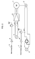
- Fig. 2 is a circuit diagram in which a motor driving device is compared with a motor-brake-releasing-device of a basic type.
- a motor shaft is locked with brake 2, thereby fixing a final object of the motor.
- a controller (not shown) drives motor 1
- a latch circuit (not shown) turns motor-driving-signal 3 active, and energizes relay K1-functioning as a switch-via driver 4.
- first contact K11 and second contact K12 of relay K1 close in response to the energizing of relay K1, so that ac power supply 5 powers servo-amplifier 6, which drives motor 1.
- a servo control system (not shown) starts controlling using signals of an encoder (not shown) indicating rotating amount of the shaft of motor 1.
- the servo control system confirms servo-lock-status, counts timing to turn brake-releasing-signal 7 active through a latch circuit (not shown), and energizes relay K2-functioning as a switch-via driver 8.
- Contact K21 of relay K2 closes responsive to the energizing of relay K2, and an electromagnetic brake 2 is powered by a power supply derived from the full-wave rectification of ac power supply 9, whereby brake 2 locking a motor shaft is released.
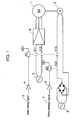
- Fig. 1 is a circuit diagram of a motor driving device and a motor-brake-releasing-device in accordance with the first exemplary embodiment of the present invention.
- a power supply for releasing an electromagnetic brake which locks a motor shaft, is supplied to the brake in an AND form, whereby the motor-brake-releasing-device releases the brake.
- the AND form is produced by a relay contact (switch), which turns conductive at operating the motor, and another relay contact (switch), which turns conductive at permitting the motor to operate.
- third contact K13 of relay K1-contact K13 being energized when motor-driving-signal 3 turns active-is coupled to a power line of a brake-releasing-power-supply in series.
- Contact K13 turns conductive when motor-driving-signal 3 turns active.
- This structure allows two contacts K13 and K21 to be coupled in series, and provides a power supply for releasing brake 2 via these two contacts, whereby brake 2 can be released only when the motor is driven (contact K 13 is closed) and the motor brake is permitted to be released (contact K21 is closed).
- the power for releasing the brake is supplied to the electromagnetic brake following the result of AND signal produced by the motor-driving-signal and the brake-release-permitting-signal.
- the brake is released as discussed above, thus the brake is never released when the motor is not driven.
- the structure shown in Fig. 1 provides a safer mechanism than that shown in Fig. 2.
- two relay contacts K21, K13 are coupled in series, there are less chances for the contacts to be melt comparing with a single contact shown in Fig. 2.
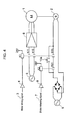
- Fig. 3 is a circuit diagram of a motor driving device and a motor-brake-releasing-device in accordance with the second exemplary embodiment of the present invention.
- the same elements as those in Fig. 2 are denoted with the same reference marks and the descriptions thereof are omitted.
- a feature of the second embodiment is to input motor-driving-signal 3 and brake-releasing-signal 7 to AND gate 15, and an output terminal of gate 15 is coupled to relay K2 via driver 8.
- AND gate 15 the AND of motor-driving-signal 3 and brake-releasing-signal 7 can be produced by software, thereby controlling relay K2 via driver 8.
- the power for releasing the brake is supplied to the electromagnetic brake following the result of AND signal produced by the motor-driving-signal and the brake-release-permitting-signal. Since the brake is released as discussed above, the brake is never released when the motor is not driven. As a result, the structure shown in Fig. 3 provides a safer mechanism than that shown in Fig. 2.
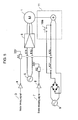
- Fig. 4 is a circuit diagram of a motor driving device and a motor-brake-releasing-device in accordance with the third exemplary embodiment of the present invention.
- the power supply of the electromagnetic brake can be released by an operator when the motor is not driven.
- Fig. 4 the same elements as shown in Fig. 1 are denoted with the same reference marks, and the descriptions thereof are omitted.
- a final object of motor 1 is interfered with a jig or the like, the servo control system detects excess load, which shuts off both a motor-driving-system and a brake system. In this case, a power supply of the servo control system is once turned off, then turned on again and necessary steps for correcting the interference status are taken for removing the interference from the final object.
- servo amplifier 6 detects overload and shouts off instantly after the servo control system is powered on. Therefore, the interference may not be avoided, and if not, another way to avoid the interference should be taken, i.e., fixed sections which fix the entire machine are dismounted and the entire machine must be moved.
- momentary switch 10a is coupled to contacts K13 and K21 in parallel so that switch 10a bypasses a series connection of contacts K13 and K21. If the servo control system is powered on, i.e., ac power supply 9 is powered on, this structure allows brake 2 to be released while an operator depresses switch 10a without driving motor 1. The interference with the final object can be avoided thanks to this mechanism. When equipment including the device of the present invention is moved to another place, an operator can change a posture of the final object without using a power supply of the equipment. This is another advantage of the third embodiment.
- Fig. 5 is a circuit diagram of a motor driving device and a motor-brake-releasing-device in accordance with the fourth exemplary embodiment of the present invention.
- the fourth embodiment shown in Fig. 5 differs from the third embodiment shown in Fig. 4 in the following point:
- switch 10a is disposed at machine 11 including the brake. Therefore, even if a controller is away from the final object, the removal operation of the interference with the final object can be carried out with ease near the final object.
- Fig. 6 is a circuit diagram of a motor driving device and a motor-brake-releasing-device in accordance with the fifth exemplary embodiment of the present invention.
- a battery is used as a power supply for releasing an electromagnetic brake.
- ac power supply 9 e.g. a commercial power supply
- machine 11 is coupled to battery 20 via connector 12 instead.
- ac power supply 9 e.g. a commercial power supply
- using battery 20 allows the brake to be released.
- the battery 20 is used as the power supply for releasing the electromagnetic brake, thus the motor brake can be released even in the condition where an ac power supply is not available.
- Fig. 7 is a circuit diagram of a motor driving device and a motor-brake-releasing-device in accordance with the sixth exemplary embodiment of the present invention.
- battery 20 is used as another power supply for releasing the brake in addition to a dc power supply which is derived from the full-wave rectification of ac power supply 9 (e.g. commercial power supply).
- ac power supply 9 e.g. commercial power supply
- the power cable of this dc power supply is not necessarily dismounted.
- alternate switch 13 is disposed in machine 11 for switching ac power supply 9 to battery 20 or vice versa as a brake-releasing-power-supply.
- This structure allows electrical collision between a de power supply-derived from the full-wave rectification of ac power supply 9-and battery 20 to be avoided because when the brake-releasing-power-supply is switched to battery 20, the power line from the dc power supply is cut off simultaneously.
- Fig. 8 is a circuit diagram of a motor driving device and a motor-brake-releasing-device in accordance with the seventh exemplary embodiment of the present invention.
- the battery is protected from spark-noise (counter electromotive force) due to an electromagnetic-brake-coil when the power supply of the electromagnetic brake is shut off.
- the releasing-power-supply of brake 2 When the releasing-power-supply of brake 2 is switched to battery 20 and momentary switch 10b for releasing the motor brake is turned open from being closed, the counter electromotive force due to the coil of brake 2 occurs at the grounding side of the power line.
- the potential of this negative voltage is more than twice of the power supply voltage. If this negative voltage is repeatedly applied, a voltage-regulation-capacitor (not shown) and battery 20 may be damaged.
- the voltage-regulation-capacitor is, e.g., a smoothing capacitor for a dc voltage derived from the full-wave-rectification of ac power supply 9.
- diode 14 is coupled as follows in order to absorb the negative voltage: the cathode of diode 14 is coupled to a positive electrode of the brake coil viewed from the releasing-power-supply of the motor brake, and the anode of diode 14 is coupled to a negative electrode (grounding) of the brake coil.
- diode 14 is coupled in parallel with the brake coil, i.e., diode 14 functions as a flywheel-diode (damper diode) and absorbs the negative voltage (surge voltage.)
- This structure allows the voltage-regulation-capacitor and the battery to be protected from the negative voltage (surge voltage) produced on the grounding side of the power line of the power supply for releasing the motor brake.
- the negative voltage is produced due to the counter-electromotive-force by the coil of the electromagnetic brake when the power supply is shut off.
Landscapes
- Engineering & Computer Science (AREA)
- Mechanical Engineering (AREA)
- Transportation (AREA)
- Stopping Of Electric Motors (AREA)
- Manipulator (AREA)
- Braking Arrangements (AREA)
- Connection Of Motors, Electrical Generators, Mechanical Devices, And The Like (AREA)
Abstract
Description
- The present invention relates to a break releasing device of a motor equipped in an apparatus having a mechanism locking a motor shaft when the power is turned off.
- A motor driving device for driving a motor and a break releasing device for releasing an electromagnetic break, which locks a motor shaft, have been independently provided, and the electromagnetic break cannot be released by hand. Because of this independent installation of the motor driving device and the break releasing device, the following inconveniences have occurred: When a motor driving system encounters a trouble, a motor does not produce torque because a driving current stops flowing to the motor. Although no torque is available in the motor, the electromagnetic brake is released or left released. As a result, a final object of the motor shaft may drop due to its own weight when the final object works in the gravity direction. When the final object interferes with an obstacle, a servo control system detects an overload status, so that the interference status cannot be avoided because the motor cannot be driven.
- The present invention addresses the problems discussed above and aims to prevent a motor brake from being released at motor's non-driven status and provide a motor-brake-releasing-device assuring safer operation than ever.
- The motor-brake-releasing-device of the present invention comprises the following elements:
- an electromagnetic brake for locking a motor shaft; and
- a switch disposed between the electromagnetic brake and its releasing-power-supply, and the switch being operated by an AND signal of a motor driving signal and a motor-brake releasing signal. This structure prevents the brake from being released when the motor is not driven, thus the structure assures safer operation of the motor than ever.
- Another motor-brake-releasing-device of the present invention comprises the following elements:
- an electromagnetic brake for locking a motor shaft;
- a battery functioning as a power supply for releasing the electromagnetic brake; and
- a switch disposed between the battery and the electromagnetic brake for releasing a motor brake. This structure employs the battery as the power supply for releasing the electromagnetic brake, thus it is beneficial that the motor brake can be released even when a power supply of a servo-control system is not powered on.
-
- Fig. 1 is a circuit diagram of a motor driving device and a motor-brake-releasing-device in accordance with a first exemplary embodiment of the present invention.
- Fig. 2 is a circuit diagram in which a motor driving device is compared with a motor-brake-releasing-device of a basic type.
- Fig. 3 is a circuit diagram of a motor driving device and a motor-brake-releasing-device in accordance with a second exemplary embodiment of the present invention.
- Fig. 4 is a circuit diagram of a motor driving device and a motor-brake-releasing-device in accordance with a third exemplary embodiment of the present invention.
- Fig. 5 is a circuit diagram of a motor driving device and a motor-brake-releasing-device in accordance with a fourth exemplary embodiment of the present invention.
- Fig. 6 is a circuit diagram of a motor driving device and a motor-brake-releasing-device in accordance with a fifth exemplary embodiment of the present invention.
- Fig. 7 is a circuit diagram of a motor driving device and a motor-brake-releasing-device in accordance with a sixth exemplary embodiment of the present invention.
- Fig. 8 is a circuit diagram of a motor driving device and a motor-brake-releasing-device in accordance with a seventh exemplary embodiment of the present invention.
- Fig. 2 is a circuit diagram in which a motor driving device is compared with a motor-brake-releasing-device of a basic type. In Fig. 2, when
motor 1 is not driven, a motor shaft is locked withbrake 2, thereby fixing a final object of the motor. - When a controller (not shown) drives
motor 1, a latch circuit (not shown) turns motor-driving-signal 3 active, and energizes relay K1-functioning as a switch-viadriver 4. Then first contact K11 and second contact K12 of relay K1 close in response to the energizing of relay K1, so thatac power supply 5 powers servo-amplifier 6, which drivesmotor 1. A servo control system (not shown) starts controlling using signals of an encoder (not shown) indicating rotating amount of the shaft ofmotor 1. - Then the servo control system confirms servo-lock-status, counts timing to turn brake-releasing-
signal 7 active through a latch circuit (not shown), and energizes relay K2-functioning as a switch-viadriver 8. Contact K21 of relay K2 closes responsive to the energizing of relay K2, and anelectromagnetic brake 2 is powered by a power supply derived from the full-wave rectification ofac power supply 9, wherebybrake 2 locking a motor shaft is released. As discussed above, there is no problem in a normal operation. - However, when the servo control system carries out, with some reason, driving the motor and releasing the brake independently, the following problem occurs: For instance, in Fig. 2, assume that the final object, driven by the motor, has a mechanism working in the gravity direction. In this case, when only motor-driving-
signal 3 turns to non-active from servo-lock status, i.e., when the servo control system ofmotor 1 is shut off, the final object is to drop due to its own weight ifbrake 2 is left released. - A motor-brake-releasing-device of the present invention, this device being expected to solve the problem discussed above, is demonstrated hereinafter with reference to the accompanying drawings.
- Fig. 1 is a circuit diagram of a motor driving device and a motor-brake-releasing-device in accordance with the first exemplary embodiment of the present invention. In the first embodiment shown in Fig. 1, a power supply for releasing an electromagnetic brake, which locks a motor shaft, is supplied to the brake in an AND form, whereby the motor-brake-releasing-device releases the brake. The AND form is produced by a relay contact (switch), which turns conductive at operating the motor, and another relay contact (switch), which turns conductive at permitting the motor to operate.
- In the first embodiment shown in Fig. 1, the following points are different from the circuit diagram shown in Fig. 2: In the first embodiment, third contact K13 of relay K1-contact K13 being energized when motor-driving-
signal 3 turns active-is coupled to a power line of a brake-releasing-power-supply in series. Contact K13 turns conductive when motor-driving-signal 3 turns active. - This structure allows two contacts K13 and K21 to be coupled in series, and provides a power supply for releasing
brake 2 via these two contacts, wherebybrake 2 can be released only when the motor is driven (contact K 13 is closed) and the motor brake is permitted to be released (contact K21 is closed). - In the first embodiment as discussed above, the power for releasing the brake is supplied to the electromagnetic brake following the result of AND signal produced by the motor-driving-signal and the brake-release-permitting-signal. The brake is released as discussed above, thus the brake is never released when the motor is not driven. As a result, the structure shown in Fig. 1 provides a safer mechanism than that shown in Fig. 2. Further, since two relay contacts K21, K13 are coupled in series, there are less chances for the contacts to be melt comparing with a single contact shown in Fig. 2.
- Fig. 3 is a circuit diagram of a motor driving device and a motor-brake-releasing-device in accordance with the second exemplary embodiment of the present invention. In Fig. 3, the same elements as those in Fig. 2 are denoted with the same reference marks and the descriptions thereof are omitted.
- A feature of the second embodiment is to input motor-driving-
signal 3 and brake-releasing-signal 7 to ANDgate 15, and an output terminal ofgate 15 is coupled to relay K2 viadriver 8. Instead of ANDgate 15, the AND of motor-driving-signal 3 and brake-releasing-signal 7 can be produced by software, thereby controlling relay K2 viadriver 8. - In the second embodiment, the power for releasing the brake is supplied to the electromagnetic brake following the result of AND signal produced by the motor-driving-signal and the brake-release-permitting-signal. Since the brake is released as discussed above, the brake is never released when the motor is not driven. As a result, the structure shown in Fig. 3 provides a safer mechanism than that shown in Fig. 2.
- Fig. 4 is a circuit diagram of a motor driving device and a motor-brake-releasing-device in accordance with the third exemplary embodiment of the present invention. In the third embodiment, the power supply of the electromagnetic brake can be released by an operator when the motor is not driven. In Fig. 4, the same elements as shown in Fig. 1 are denoted with the same reference marks, and the descriptions thereof are omitted.
- In the first embodiment illustrated in Fig. 1, when both contacts K13 and K21 are closed by a servo control system, a power supply derived from the full-wave rectification of
ac power supply 9 is supplied tobrake 2 and releasesbrake 2. - In Fig.1, if a final object of
motor 1 is interfered with a jig or the like, the servo control system detects excess load, which shuts off both a motor-driving-system and a brake system. In this case, a power supply of the servo control system is once turned off, then turned on again and necessary steps for correcting the interference status are taken for removing the interference from the final object. - However, if the final object is heavily interfered and is applied with large force, and when offset load is applied to the shaft of
motor 1, servo lock status cannot be maintained although an operator tries to drivemotor 1. Thusservo amplifier 6 detects overload and shouts off instantly after the servo control system is powered on. Therefore, the interference may not be avoided, and if not, another way to avoid the interference should be taken, i.e., fixed sections which fix the entire machine are dismounted and the entire machine must be moved. - In the third embodiment shown in Fig. 4,
momentary switch 10a is coupled to contacts K13 and K21 in parallel so thatswitch 10a bypasses a series connection of contacts K13 and K21. If the servo control system is powered on, i.e.,ac power supply 9 is powered on, this structure allowsbrake 2 to be released while an operator depressesswitch 10a without drivingmotor 1. The interference with the final object can be avoided thanks to this mechanism. When equipment including the device of the present invention is moved to another place, an operator can change a posture of the final object without using a power supply of the equipment. This is another advantage of the third embodiment. - Fig. 5 is a circuit diagram of a motor driving device and a motor-brake-releasing-device in accordance with the fourth exemplary embodiment of the present invention. The fourth embodiment shown in Fig. 5 differs from the third embodiment shown in Fig. 4 in the following point: In the fourth embodiment,
switch 10a is disposed atmachine 11 including the brake. Therefore, even if a controller is away from the final object, the removal operation of the interference with the final object can be carried out with ease near the final object. - Fig. 6 is a circuit diagram of a motor driving device and a motor-brake-releasing-device in accordance with the fifth exemplary embodiment of the present invention. In the fifth embodiment, a battery is used as a power supply for releasing an electromagnetic brake.
- To be more specific, in the fifth embodiment shown in Fig. 6, connecting cables-shown in Fig. 5 of the fourth embodiment-between ac power supply 9 (e.g. a commercial power supply) and
machine 11 are dismounted, andmachine 11 is coupled tobattery 20 viaconnector 12 instead. Without connection toac power supply 9, usingbattery 20 allows the brake to be released. As such, thebattery 20 is used as the power supply for releasing the electromagnetic brake, thus the motor brake can be released even in the condition where an ac power supply is not available. - Fig. 7 is a circuit diagram of a motor driving device and a motor-brake-releasing-device in accordance with the sixth exemplary embodiment of the present invention. In this embodiment,
battery 20 is used as another power supply for releasing the brake in addition to a dc power supply which is derived from the full-wave rectification of ac power supply 9 (e.g. commercial power supply). The power cable of this dc power supply is not necessarily dismounted. As shown in Fig. 7,alternate switch 13 is disposed inmachine 11 for switchingac power supply 9 tobattery 20 or vice versa as a brake-releasing-power-supply. This structure allows electrical collision between a de power supply-derived from the full-wave rectification of ac power supply 9-andbattery 20 to be avoided because when the brake-releasing-power-supply is switched tobattery 20, the power line from the dc power supply is cut off simultaneously. - Fig. 8 is a circuit diagram of a motor driving device and a motor-brake-releasing-device in accordance with the seventh exemplary embodiment of the present invention. In the seventh embodiment, the battery is protected from spark-noise (counter electromotive force) due to an electromagnetic-brake-coil when the power supply of the electromagnetic brake is shut off.
- When the releasing-power-supply of
brake 2 is switched tobattery 20 andmomentary switch 10b for releasing the motor brake is turned open from being closed, the counter electromotive force due to the coil ofbrake 2 occurs at the grounding side of the power line. The potential of this negative voltage is more than twice of the power supply voltage. If this negative voltage is repeatedly applied, a voltage-regulation-capacitor (not shown) andbattery 20 may be damaged. The voltage-regulation-capacitor is, e.g., a smoothing capacitor for a dc voltage derived from the full-wave-rectification ofac power supply 9. Thus as shown in Fig. 8,diode 14 is coupled as follows in order to absorb the negative voltage: the cathode ofdiode 14 is coupled to a positive electrode of the brake coil viewed from the releasing-power-supply of the motor brake, and the anode ofdiode 14 is coupled to a negative electrode (grounding) of the brake coil. In other words,diode 14 is coupled in parallel with the brake coil, i.e.,diode 14 functions as a flywheel-diode (damper diode) and absorbs the negative voltage (surge voltage.) - This structure allows the voltage-regulation-capacitor and the battery to be protected from the negative voltage (surge voltage) produced on the grounding side of the power line of the power supply for releasing the motor brake. The negative voltage is produced due to the counter-electromotive-force by the coil of the electromagnetic brake when the power supply is shut off.
Claims (5)
- A motor brake releasing device comprising:an electromagnetic brake (2) for locking a motor shaft; anda switch (K13) disposed between said electromagnetic brake (2) and a releasing-power-supply of said brake (2), and said switch (K13) being operated by an AND signal produced by a motor-driving-signal (3) and a motor-brake-release-permitting signal (7).
- The motor brake releasing device of claim 1 further comprising:another switch (10a,10b) for releasing a motor brake (2) and disposed in parallel with said switch (K13).
- The motor brake releasing device of claim 2, wherein said another (10a) switch is disposed on a machine side including said electromagnetic brake (2).
- A motor brake releasing device comprising:an electromagnetic brake (2) for locking a motor shaft;a battery (20) as a first power supply for releasing said electromagnetic brake (2);a first switch (10b) for releasing a motor brake (2) and disposed between said battery (20) and said electromagnetic brake (2);an AC power supply (9) as a second power supply for releasing said electromagnetic brake (2), anda second switch (13) for switching the releasing power supply to one of said battery (20) (the first power supply) and said AC power supply (9) (the second power supply).
- The motor brake releasing device of claim 4,
wherein said first (10b) and said second (13) switches are disposed on a machine side including said electromagnetic brake (2).
Applications Claiming Priority (2)
| Application Number | Priority Date | Filing Date | Title |
|---|---|---|---|
| JP2000164292A JP2001346400A (en) | 2000-06-01 | 2000-06-01 | Motor brake releasing device |
| EP01113429A EP1160141A3 (en) | 2000-06-01 | 2001-06-01 | Motor break releasing device |
Related Parent Applications (1)
| Application Number | Title | Priority Date | Filing Date |
|---|---|---|---|
| EP01113429A Division EP1160141A3 (en) | 2000-06-01 | 2001-06-01 | Motor break releasing device |
Publications (1)
| Publication Number | Publication Date |
|---|---|
| EP1775187A2 true EP1775187A2 (en) | 2007-04-18 |
Family
ID=18667934
Family Applications (2)
| Application Number | Title | Priority Date | Filing Date |
|---|---|---|---|
| EP01113429A Withdrawn EP1160141A3 (en) | 2000-06-01 | 2001-06-01 | Motor break releasing device |
| EP07100612A Withdrawn EP1775187A2 (en) | 2000-06-01 | 2001-06-01 | Motor Break Releasing Device |
Family Applications Before (1)
| Application Number | Title | Priority Date | Filing Date |
|---|---|---|---|
| EP01113429A Withdrawn EP1160141A3 (en) | 2000-06-01 | 2001-06-01 | Motor break releasing device |
Country Status (3)
| Country | Link |
|---|---|
| US (1) | US6498448B2 (en) |
| EP (2) | EP1160141A3 (en) |
| JP (1) | JP2001346400A (en) |
Cited By (1)
| Publication number | Priority date | Publication date | Assignee | Title |
|---|---|---|---|---|
| EP1935837A1 (en) * | 2006-12-21 | 2008-06-25 | Bubenzer Bremsen Gerhard Bubenzer Ing. GmbH | Electrical control for a braking device |
Families Citing this family (10)
| Publication number | Priority date | Publication date | Assignee | Title |
|---|---|---|---|---|
| KR100488522B1 (en) * | 2003-02-07 | 2005-05-11 | 삼성전자주식회사 | Control apparatus for a motor |
| JP4320556B2 (en) * | 2003-04-02 | 2009-08-26 | 株式会社安川電機 | Industrial robot controller |
| JP2005143257A (en) * | 2003-11-10 | 2005-06-02 | Nissan Motor Co Ltd | Servo system |
| JP2005209061A (en) * | 2004-01-26 | 2005-08-04 | Yaskawa Electric Corp | Automatic machine control unit |
| US10286883B2 (en) | 2016-05-10 | 2019-05-14 | Sharp Kabushiki Kaisha | Motor-driven traveling device |
| JP6776878B2 (en) * | 2016-12-21 | 2020-10-28 | トヨタ自動車株式会社 | Electromagnetic brake wear detector |
| US10680538B2 (en) * | 2017-09-28 | 2020-06-09 | Otis Elevator Company | Emergency braking for a drive system |
| JP7091642B2 (en) * | 2017-12-11 | 2022-06-28 | 日本電産株式会社 | Brake drive control circuit and its failure detection method |
| JP7281699B2 (en) * | 2017-12-11 | 2023-05-26 | ニデック株式会社 | BRAKE DRIVE CONTROL CIRCUIT AND ITS FAILURE DETECTION METHOD |
| WO2022210290A1 (en) * | 2021-03-31 | 2022-10-06 | ファナック株式会社 | Brake control device and motor drive device |
Family Cites Families (23)
| Publication number | Priority date | Publication date | Assignee | Title |
|---|---|---|---|---|
| US2426071A (en) * | 1943-10-28 | 1947-08-19 | Westinghouse Electric Corp | Alternating-current motor system |
| US3971971A (en) * | 1974-11-15 | 1976-07-27 | Ingersoll-Rand Company | Electric hoist control and braking system |
| US4361312A (en) * | 1979-02-07 | 1982-11-30 | Columbus Mckinnon Corporation | Precise load positioner |
| JPH0729746B2 (en) * | 1984-01-11 | 1995-04-05 | 株式会社日立製作所 | Elevator emergency stop control device |
| US4841215A (en) * | 1987-06-22 | 1989-06-20 | Lift Tech International Inc. | D.C. solenoid control circuit |
| JP2823079B2 (en) * | 1989-11-20 | 1998-11-11 | トキコ株式会社 | Industrial robot |
| JP2950564B2 (en) * | 1990-01-24 | 1999-09-20 | 松下電器産業株式会社 | Industrial robot |
| JPH0416470A (en) * | 1990-05-09 | 1992-01-21 | Mitsubishi Electric Corp | Safety device for elevator |
| JPH0754487Y2 (en) * | 1990-09-28 | 1995-12-18 | 新明和工業株式会社 | Multi-level parking facility using solar cells as a power source |
| JPH04185204A (en) * | 1990-11-20 | 1992-07-02 | Kubota Corp | Small motor-driven vehicle |
| US5333706A (en) * | 1991-10-22 | 1994-08-02 | Akebono Brake Industry Co., Ltd. | Brake apparatus for a vehicle |
| JPH05130579A (en) * | 1991-10-31 | 1993-05-25 | Fuji Photo Film Co Ltd | Image communication device |
| DE4232402C5 (en) * | 1992-09-26 | 2005-10-27 | Marquardt Gmbh | Braking circuit for an electric motor |
| US5394069A (en) * | 1993-03-08 | 1995-02-28 | International Business Machines Corporation | Mechanical brake hold circuit for an electric motor |
| DE4307356A1 (en) * | 1993-03-09 | 1994-09-15 | Bosch Gmbh Robert | Series motor, especially universal motor, with a braking device |
| JPH0715989A (en) * | 1993-06-30 | 1995-01-17 | Matsushita Electric Works Ltd | Motor controller |
| JP3834073B2 (en) * | 1994-06-22 | 2006-10-18 | 株式会社安川電機 | How to stop the hoisting / unwinding machine |
| JP3003768B2 (en) * | 1994-10-31 | 2000-01-31 | 株式会社安川電機 | Method and apparatus for releasing joint constraint of articulated robot |
| JPH08171411A (en) | 1994-12-19 | 1996-07-02 | Fanuc Ltd | Robot butt mastering method |
| JPH08202962A (en) * | 1995-01-30 | 1996-08-09 | Amenitetsukusu:Kk | Optical warning section indicator |
| US5893432A (en) * | 1996-12-31 | 1999-04-13 | Inventio Ag | Controlled emergency stop apparatus for elevators |
| JPH1166993A (en) * | 1997-08-11 | 1999-03-09 | Yaskawa Electric Corp | Contact point welding detecting device of motor having brake |
| JP2000296492A (en) * | 1999-04-15 | 2000-10-24 | Matsushita Electric Ind Co Ltd | Motor brake device for robot |
-
2000
- 2000-06-01 JP JP2000164292A patent/JP2001346400A/en active Pending
-
2001
- 2001-06-01 EP EP01113429A patent/EP1160141A3/en not_active Withdrawn
- 2001-06-01 US US09/873,116 patent/US6498448B2/en not_active Expired - Lifetime
- 2001-06-01 EP EP07100612A patent/EP1775187A2/en not_active Withdrawn
Cited By (1)
| Publication number | Priority date | Publication date | Assignee | Title |
|---|---|---|---|---|
| EP1935837A1 (en) * | 2006-12-21 | 2008-06-25 | Bubenzer Bremsen Gerhard Bubenzer Ing. GmbH | Electrical control for a braking device |
Also Published As
| Publication number | Publication date |
|---|---|
| JP2001346400A (en) | 2001-12-14 |
| EP1160141A2 (en) | 2001-12-05 |
| US20020017882A1 (en) | 2002-02-14 |
| EP1160141A3 (en) | 2003-07-02 |
| US6498448B2 (en) | 2002-12-24 |
Similar Documents
| Publication | Publication Date | Title |
|---|---|---|
| US6498448B2 (en) | Motor break releasing device | |
| CN109159669B (en) | Protection system and method for electric drive system | |
| EP2008358A1 (en) | Control system for an electric motor | |
| CA2666250A1 (en) | Electric power converter | |
| CN109166744B (en) | Dual-power automatic transfer switch and transfer control method thereof | |
| EP3753775A1 (en) | Electric vehicle drive system, backup power supply device and method therefor | |
| CN109039221B (en) | Active short circuit and motor controller | |
| US10933735B2 (en) | Vehicle | |
| WO1995024297A1 (en) | Control device for industrial robots | |
| JP7358651B2 (en) | Motor control system and motor control device | |
| CN108683243B (en) | Power management system and method for motor-driven quadruped robot | |
| JP2866007B2 (en) | Control device for printing press | |
| CN113541122A (en) | Protection device and method for servo driver and servo motor | |
| CN110733041B (en) | Accuse drives integrative power module | |
| US20230231506A1 (en) | Protection apparatus and brushless motor system | |
| WO2002054567A3 (en) | Electronically commutated motor | |
| JP2001506050A (en) | Safety relay | |
| KR101239436B1 (en) | Switch operation device and switch for three-phase system | |
| US12009654B2 (en) | Motor control system and motor control device | |
| CN113021332B (en) | Industrial robot control system and control equipment | |
| CN112388667B (en) | Robot joint shaft driving structure, robot and control method thereof | |
| CN218630548U (en) | Robot braking system and robot | |
| EP4329186A1 (en) | Power tool | |
| JP3511563B2 (en) | Electric power steering control device | |
| CN109723316B (en) | High-safety door machine safety chain control system |
Legal Events
| Date | Code | Title | Description |
|---|---|---|---|
| PUAI | Public reference made under article 153(3) epc to a published international application that has entered the european phase |
Free format text: ORIGINAL CODE: 0009012 |
|
| AC | Divisional application: reference to earlier application |
Ref document number: 1160141 Country of ref document: EP Kind code of ref document: P |
|
| AK | Designated contracting states |
Kind code of ref document: A2 Designated state(s): DE FR GB SE |
|
| RTI1 | Title (correction) |
Free format text: MOTOR BRAKE RELEASING DEVICE |
|
| RAP1 | Party data changed (applicant data changed or rights of an application transferred) |
Owner name: PANASONIC CORPORATION |
|
| STAA | Information on the status of an ep patent application or granted ep patent |
Free format text: STATUS: THE APPLICATION HAS BEEN WITHDRAWN |
|
| 18W | Application withdrawn |
Effective date: 20121015 |