EP1775178A2 - Passenger seat air bag - Google Patents
Passenger seat air bag Download PDFInfo
- Publication number
- EP1775178A2 EP1775178A2 EP06019503A EP06019503A EP1775178A2 EP 1775178 A2 EP1775178 A2 EP 1775178A2 EP 06019503 A EP06019503 A EP 06019503A EP 06019503 A EP06019503 A EP 06019503A EP 1775178 A2 EP1775178 A2 EP 1775178A2
- Authority
- EP
- European Patent Office
- Prior art keywords
- airbag
- seat pan
- inflator
- gas
- retainer
- Prior art date
- Legal status (The legal status is an assumption and is not a legal conclusion. Google has not performed a legal analysis and makes no representation as to the accuracy of the status listed.)
- Withdrawn
Links
- 101150006573 PAN1 gene Proteins 0.000 abstract description 36
- 238000003780 insertion Methods 0.000 description 17
- 230000037431 insertion Effects 0.000 description 17
- 238000009434 installation Methods 0.000 description 5
- 230000000694 effects Effects 0.000 description 4
- 238000000034 method Methods 0.000 description 4
- 230000002093 peripheral effect Effects 0.000 description 4
- 238000002347 injection Methods 0.000 description 2
- 239000007924 injection Substances 0.000 description 2
- 239000000463 material Substances 0.000 description 2
- 239000004744 fabric Substances 0.000 description 1
- 238000005096 rolling process Methods 0.000 description 1
Images





Classifications
-
- B—PERFORMING OPERATIONS; TRANSPORTING
- B60—VEHICLES IN GENERAL
- B60N—SEATS SPECIALLY ADAPTED FOR VEHICLES; VEHICLE PASSENGER ACCOMMODATION NOT OTHERWISE PROVIDED FOR
- B60N2/00—Seats specially adapted for vehicles; Arrangement or mounting of seats in vehicles
- B60N2/24—Seats specially adapted for vehicles; Arrangement or mounting of seats in vehicles for particular purposes or particular vehicles
- B60N2/42—Seats specially adapted for vehicles; Arrangement or mounting of seats in vehicles for particular purposes or particular vehicles the seat constructed to protect the occupant from the effect of abnormal g-forces, e.g. crash or safety seats
- B60N2/427—Seats or parts thereof displaced during a crash
- B60N2/42727—Seats or parts thereof displaced during a crash involving substantially rigid displacement
- B60N2/42754—Seats or parts thereof displaced during a crash involving substantially rigid displacement of the cushion
- B60N2/42763—Seats or parts thereof displaced during a crash involving substantially rigid displacement of the cushion with anti-submarining systems
-
- B—PERFORMING OPERATIONS; TRANSPORTING
- B60—VEHICLES IN GENERAL
- B60R—VEHICLES, VEHICLE FITTINGS, OR VEHICLE PARTS, NOT OTHERWISE PROVIDED FOR
- B60R21/00—Arrangements or fittings on vehicles for protecting or preventing injuries to occupants or pedestrians in case of accidents or other traffic risks
- B60R21/02—Occupant safety arrangements or fittings, e.g. crash pads
- B60R21/16—Inflatable occupant restraints or confinements designed to inflate upon impact or impending impact, e.g. air bags
- B60R21/26—Inflatable occupant restraints or confinements designed to inflate upon impact or impending impact, e.g. air bags characterised by the inflation fluid source or means to control inflation fluid flow
-
- B—PERFORMING OPERATIONS; TRANSPORTING
- B60—VEHICLES IN GENERAL
- B60R—VEHICLES, VEHICLE FITTINGS, OR VEHICLE PARTS, NOT OTHERWISE PROVIDED FOR
- B60R21/00—Arrangements or fittings on vehicles for protecting or preventing injuries to occupants or pedestrians in case of accidents or other traffic risks
- B60R21/02—Occupant safety arrangements or fittings, e.g. crash pads
- B60R21/16—Inflatable occupant restraints or confinements designed to inflate upon impact or impending impact, e.g. air bags
- B60R21/26—Inflatable occupant restraints or confinements designed to inflate upon impact or impending impact, e.g. air bags characterised by the inflation fluid source or means to control inflation fluid flow
- B60R21/261—Inflatable occupant restraints or confinements designed to inflate upon impact or impending impact, e.g. air bags characterised by the inflation fluid source or means to control inflation fluid flow with means other than bag structure to diffuse or guide inflation fluid
- B60R2021/2612—Gas guiding means, e.g. ducts
-
- B—PERFORMING OPERATIONS; TRANSPORTING
- B60—VEHICLES IN GENERAL
- B60R—VEHICLES, VEHICLE FITTINGS, OR VEHICLE PARTS, NOT OTHERWISE PROVIDED FOR
- B60R21/00—Arrangements or fittings on vehicles for protecting or preventing injuries to occupants or pedestrians in case of accidents or other traffic risks
- B60R21/02—Occupant safety arrangements or fittings, e.g. crash pads
- B60R21/16—Inflatable occupant restraints or confinements designed to inflate upon impact or impending impact, e.g. air bags
- B60R21/20—Arrangements for storing inflatable members in their non-use or deflated condition; Arrangement or mounting of air bag modules or components
- B60R21/207—Arrangements for storing inflatable members in their non-use or deflated condition; Arrangement or mounting of air bag modules or components in vehicle seats
Definitions
- the present invention relates to a passenger constraining apparatus for constraining a passenger on a seat of a vehicle such as an automotive vehicle upon collision and, more specifically, to a passenger constraining apparatus configured to prevent a lumber part of the passenger from moving forward or downward by arranging an airbag arranged between a seat pan and a seat cushion and causing the airbag to be inflated upon front collision of the vehicle to push a front portion of the seat cushion from the lower side. Further specifically, the present invention relates to a passenger constraining apparatus in which an inflator is installed outside of the airbag and gas is introduced into the airbag from the inflator by a gas introducing member such as a duct.
- JP-A-2002-145002 discloses a passenger constraining apparatus in which an inflatable airbag is arranged between the seat cushion and the seat pan, so that the front portion of the seat cushion is pushed upward by inflating the airbag upon collision of the vehicle in order to prevent a submarine phenomenon that the submarine phenomena such that the passenger tends to slip through a lower side of a lap belt upon front collision even though the seatbelt is fastened.
- an inflator gas generator for inflating the airbag is installed outside the airbag, the inflator and the airbag are connected with a pipe, and gas is introduced into the airbag from the inflator through the pipe.
- the airbag is only connected to the pipe for introducing gas by fastening a band, and is not fixed to the seat pan.
- a passenger constraining apparatus includes an airbag arranged between a seat pan and a seat cushion and is capable of being inflated so as to press the seat cushion from the lower side and an inflator for inflating the airbag, the inflator being installed outside the airbag so that gas from the inflator is introduced into the airbag, characterized in that a midsection of the airbag in the direction of the width of the seat pan is fixed to the seat pan with a mounting member, the mounting member includes an inner member arranged in the interior of the airbag for holding down a bottom portion of the airbag against the seat pan, an extending member continuing from the inner member and extending outwardly of the airbag for being fixed to the seat pan, and a gas channel passing through the extending member and being communicated with the interior of the airbag, and the gas from the inflator can be introduced into the airbag via the gas channel.
- a passenger constraining apparatus is a passenger constraining apparatus including an airbag arranged between a seat pan and a seat cushion and is capable of being inflated so as to press the seat cushion from the lower side and an inflator for inflating the airbag, the inflator being installed outside the airbag so that gas from the inflator is introduced to the interior of the airbag, characterized in that a midsection of the airbag in the direction of the width of the seat pan is fixed to the seat pan with a mounting member, the mounting member includes an inner member arranged in the interior of the airbag for holding down a bottom portion of the airbag against the seat pan, an extending member continuing from the inner member and extending outwardly of the airbag, a gas channel passing through the extending member and being communicated with the interior of the airbag, and a fixed member continuing from the inner member and extending outwardly of the airbag for being fixed to the seat pan, and the gas from the inflator can be introduced into the airbag via the gas channel.
- a passenger constraining apparatus is a passenger constraining apparatus including an airbag arranged between a seat pan and a seat cushion and is capable of being inflated so as to press the seat cushion from the lower side and an inflator for inflating the airbag, the inflator being installed outside the airbag so that gas from the inflator is introduced to the interior of the airbag, characterized in that a retainer for mounting the airbag to the seat pan is provided under the airbag, a midsection of the airbag in the direction of the width of the seat pan is fixed to the retainer with a mounting member, the mounting member includes an inner member arranged in the interior of the airbag for holding down a bottom portion of the airbag against the retainer, an extending member continuing from the inner member and extending outwardly of the airbag for being fixed to the retainer, and a gas channel passing through the extending member and being communicated with the interior of the airbag, and the gas from the inflator can be introduced into the airbag via the gas channel.
- a passenger constraining apparatus is a passenger constraining apparatus including an airbag arranged between a seat pan and a seat cushion and is capable of being inflated so as to press the seat cushion from the lower side and an inflator for inflating the airbag, the inflator being installed outside the airbag so that gas from the inflator is introduced to the interior of the airbag, characterized in that a retainer for mounting the airbag to the seat pan is provided under the airbag, a midsection of the airbag in the direction of the width of the seat pan is fixed to the retainer with a mounting member, the mounting member includes an inner member arranged in the interior of the airbag for holding down a bottom portion of the airbag against the retainer, an extending member continuing from the inner member and extending outwardly of the airbag, a gas channel passing through the extending member and being communicated with the interior of the airbag, and a fixed member continuing from the inner member and extending outwardly of the airbag for being fixed to the retainer, and the gas from the inflat
- the passenger constraining apparatus is characterized in that a diffuser for changing the direction of a gas flow discharged in the airbag from the gas channel to the direction of the width of the seat pan is provided at a position near an outlet port of the gas channel inside the airbag.
- the airbag is capable of being inflated so as to press or push a front portion of the seat cushion from the lower side.
- the midsection of the airbag in the direction of the width of the seat pan is fixed to the seat pan with the mounting member.
- the bottom portion of the airbag is held down against the seat pan with the inner member arranged in the interior of the airbag, the extending member continuing from the inner member is extended outwardly of the airbag, and is fixed to the seat pan. Accordingly, the bottom surface of the airbag is clamped and fixed between the inner member and the seat pan.
- the extending member is provided with the gas channel passing through the extending member and being communicated with the airbag, so that the gas is introduced from the inflator into the airbag through the gas channel.
- the airbag is mounted to the seat pan with the mounting member which also serves as a gas introducing member from the inflator to the interior of the airbag, it is not necessary to provide a specific part for introducing gas from the inflator to the interior of the airbag and a specific part for mounting the airbag to the seat pan separately. Accordingly, the configuration of the passenger constraining apparatus can be simplified, and the assembly work of the passenger constraining apparatus to the seat pan can be facilitated.
- the fixed member which is continued from the inner member is provided on the mounting member separately from the extending member having the gas channel to the interior of the airbag, and the fixed member is extended outwardly of the airbag and fixed to the seat pan.
- the passenger constraining apparatus in Claim 2 also achieves the same effects and advantages as the passenger constraining apparatus in Claim 1.
- the retainer of mounting the airbag to the seat pan is provided under the airbag, and the midsection of the airbag in the direction of the width of the seat pan is attached to the retainer with the mounting member.
- the extending member continuing from the inner member is extended outwardly of the airbag and fixed to the retainer by holding down the bottom portion of the airbag against the retainer with the inner member arranged in the interior of the airbag. Accordingly, the bottom portion of the airbag is clamped and fixed between the inner member and the retainer.
- the extending member is provided with the gas channel which passes through the extending member and being communicated with the interior of the airbag, so that gas is introduced into the airbag from the inflator via the gas channel.
- the airbag is mounted to the seat pan by mounting the retainer to the seat pan.
- the airbag is mounted to the retainer by the mounting member which also serves as the gas introducing member from the inflator to the interior of the airbag, it is not necessary to provide a specific part for introducing gas from the inflator to the airbag and a specific part for mounting the airbag to the retainer separately. Accordingly, the configuration of the passenger constraining apparatus can be simplified, and the assembly work of the passenger constraining apparatus to the retainer can be facilitated.
- the passenger constraining apparatus in Claim 3, can be unitized by mounting the airbag to the retainer with the mounting member in advance. Therefore, the assembly work for mounting the passenger constraining apparatus to the seat pan can be carried out quickly.
- the fixed member continued from the inner member is provided on the mounting member separately from the extending member having the gas channel to the airbag is provide separately from the extending member having the gas channel to the interior of the airbag, and the fixed member is extended outwardly of the airbag and fixed to the retainer.
- the midsection of the airbag in the direction of the width of the seat pan is mounted to the seat pan by the mounting member which also serves as the gas introducing member to the airbag, the airbag mounting member or the gas introducing member are not provided on both end sides of the airbag in the direction of the width of the seat pan. Therefore, the airbag can be extended longly from a position near the one end to a position neat the other end of the seat pan in the direction of the width, and hence the passenger constraining effect by this airbag can be improved.
- the diffuser for changing the direction of the gas flow discharged in the airbag from the gas channel to the direction of the width of the seat pan is provided at the position near the outlet port of the gas channel inside the airbag, the inflation of the airbag in the direction of the width of the seat pan is accelerated.
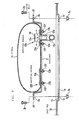
- Fig. 1 is a perspective view of a seat pan showing a passenger constraining apparatus according to an embodiment
- Fig. 2 is a cross-sectional view taken along the line II-II in Fig. 1
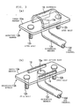
- Figs. 3(a), (b) are perspective views of an airbag mounting member of the passenger constraining apparatus
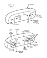
- Fig. 4 is a perspective view of the passenger constraining apparatus of Fig. 1 viewed from a bottom side of the airbag.
- Fig. 3(b) is a cross-sectional view, partly broken, of a diffuser from the mounting member in Fig. 3(a).
- Fig. 4(b) is a drawing showing a procedure of installation of the mounting member in the airbag shown in Fig. 4(a).
- a seat pan 1 is arranged on a lower side of a seat cushion (not shown) of a seat to be mounted to a vehicle, and an airbag 11 of a passenger constraining apparatus 10 is arranged above a front portion of the seat pan 1 (between the seat cushion and the seat pan 1).
- the airbag 11 extends in the direction of lateral width of the seat pan 1 (seat).
- the airbag 11 is shown in an inflated state. However, the airbag 11 is folded along an upper surface of the seat pan 1 with the thickness thereof reduced in the normal state.
- the passenger constraining apparatus 10 includes the airbag 11, mounting members 12A, 12B for mounting the airbag 11 to the seat pan 1, and an inflator 13 or the like for inflating the airbag 11.
- the inflator 13 is installed outside the airbag 11 (on a rear end side of the seat pan 1 in this embodiment), and a duct (pipe) 14 for introducing gas from the inflator 13 to the airbag 11 is provided so as to extend between the inflator 13 and the airbag 11.
- the duct 14 is led along a back (lower) surface side of the seat pan 1.
- an airbelt to be led along a front side of a passenger seated on the seat for constraining the passenger on the seat by inflating upon collision of the vehicle is provided, and the inflator 13 is a common gas supply source for the airbag 11 and the airbelt.
- a gas distributor 15 for distributing gas injected from a gas injection port to the airbag 11 and the airbelt is connected to the gas injection port (not shown) of the inflator 13.
- One end side of the duct 14 is connected to a gas outlet port of the gas distributor 15 for the airbag.
- Reference numeral 14' in Fig. 1 designates a duct which is connected at one end side to the gas outlet port of the gas distributor 15 for the airbelt. The other end side of the duct 14' is connected to the airbelt.
- the mounting member 12A is arranged at a position on the airbag 11 on one end side with respect to a center in the longitudinal direction thereof, and the mounting member 12B is arranged at a position on the airbag 11 on the other end side with respect to the center in the longitudinal direction thereof.
- the mounting member 12A also serves as a gas introducing member into the airbag 11, and the mounting member 12B is only for fixing the airbag 11 to the seat pan 1.
- the mounting member 12A includes an inner member 12a arranged in the airbag 11 for holding down a bottom surface of the airbag 11 against the sea pan 1, stud bolts 12b as fixed members projecting downward from a lower surface of the inner member 12a, an extending member 12c extending downward from the lower surface of the inner member 12a, and a gas channel 12d communicated with an upper surface side (inside the airbag 11) of the inner member 12a through the extending member 12c.
- the inner member 12a is formed into a substantially rectangular plate shape in this embodiment, and the length in the longitudinal direction is smaller than a half the length of the airbag 11 in the longitudinal direction.
- the inner member 12a is superimposed on the bottom surface of the airbag 11 with the longitudinal direction oriented in the longitudinal direction of the airbag 11.
- Two of the stud bolts 12b are provided at a distance in the longitudinal direction of the inner member 12a, and the extending member 12c is arranged between the stud bolts 12b, 12b (near a center of the inner member 12a in the longitudinal direction).
- one end side of the extending member 12c is formed of a tubular member (pipe) connected to the lower surface of the inner member 12a with the axial direction oriented in the vertical direction, and an inner side of the tubular member corresponds to the gas channel 12d.
- the gas channel 12d passes through the inner member 12a and opens at a position near the longitudinal center of the upper surface of the inner member 12a.
- An opening on the upper surface of the inner member 12a corresponds to a gas outlet port 12e.
- the extending member 12c is formed into a substantially L-shape so as to extend rearwardly of the seat pan 1 from a mid point thereof.
- the duct 14 is connected to a distal end of the extending member 12c via a joint member (not shown).
- a joint member (not shown).
- one or more of separate tubular members or joint member may be connected in series between the extending member 12c and the duct 14.
- the extending member 12c and the duct 14 (from the mounting member 12A to the end of the duct 14 on the inflator side) may be formed continuously and integrally.
- the extending member 13c and the duct 14 may be formed of flexible pipe which can be bent freely, and the extending member 12c may be connected to the duct 14 via the flexible pipe.
- a diffuser 16 for changing the direction of gas flow injected from the gas outlet port 12e into the direction longitudinally of the airbag 11 is provided on the mounting member 12A.
- the diffuser 16 has a substantially semi-cylindrical shape, and is installed on the upper surface of the inner member 12a so as to straddle the gas outlet port 12e from above with the direction of the axial centerline oriented in the longitudinal direction of the inner member 12a. Axial both end sides of the diffuser 16 are opened toward the longitudinal direction of the inner member 12a.
- the diffuser 16 may be provided integrally with the inner member 12a, or may be provided separately and mounted to the inner member 12a afterwards.
- the mounting member 12B has the same configuration as the mounting member 12A other than the point that the extending member 12c (and the gas channel 12d and the gas outlet port 12e) and the diffuser 16 are omitted from the mounting member 12A.
- a pair of bolt insertion holes 11a, 11a through which the respective stud bolts 12b, 12b of the mounting member 12A are inserted and an extending member insertion hole 11b through which the extending member 12c is inserted are provided.
- the bolt insertion holes 11b, 11b are arranged at a distance in the longitudinal direction of the airbag 11, and the extending member insertion hole 11b is provided at a position near the center between the bolt insertion holes 11a, 11a.
- a pair of bolt insertion holes 11a, 11a where the respective stud bolts 12b, 12b of the mounting member 12B are inserted are provided in an area of the bottom surface of the airbag 11 where the mounting member 12B is arranged (where the inner member 12a of the mounting member 12B is overlapped).
- bolt insertion holes 11b, 11b for the mounting member 12B are also arranged at different positions in the longitudinal direction of the airbag 11.
- the mounting members 12A, 12B are arranged in the airbag 11 through slits 11c provided on the bottom surface of the airbag 11 as shown in Fig. 4(b).
- the slits 11c are formed in an area of the bottom surface of the airbag 11 where the respective inner members 12a of the mounting members 12A, 12B are overlapped.
- the mounting members 12A, 12B are inserted into the airbag 11 from the respective slits 11c on the bottom surface of the airbag 11, respectively. Then, the respective stud bolts 12b of the mounting members 12A, 12B are extended outwardly of the airbag 11 through the respective bolt insertion holes 11a on the bottom surface of the airbag 11, and the extending member 12c of the mounting member 12A is inserted through the extending member insertion hole 11b so as to be extended outwardly of the airbag 11, and then the respective inner members 12a of the mounting members 12A, 12B are superimposed on the bottom surface of the airbag 11 (on the inner surface of the bottom portion).
- the airbag 11 is arranged on the seat pan 1 while inserting the extending member 12c and the respective stud bolts 12b extending from the bottom surface of the airbag 11 are inserted into the extending member insertion hole (reference numeral is not provided) and the respective bolt insertion holes (reference numeral is not provided) provided on the seat pan 1 respectively.
- nuts 12f are tightened onto the respective stud bolts 12b from a back side of the seat pan 1. Accordingly, the respective mounting members 12A, 12B are fixed to the seat pan 1 and the bottom surface of the airbag 11 is clamped and fixed between the respective inner members 12a of the mounting members 12A, 12B and the seat pan 1.
- the inflator 13 is mounted to a rear end portion of the seat pan 1.
- the gas distributor 15 may be connected to the inflator 13 before mounting the inflator 13 to the seat pan 1, or the gas distributor 15 may be connected to the inflator 13 after the inflator 13 is mounted to the seat pan 1.
- the extending member 12c of the mounting member 12A and the gas outlet port of the gas distributor 15 for the airbag are connected with the duct 14, whereby installation of the passenger constraining apparatus 10 to the seat pan 1 is completed.
- the airbelt is installed on the seat, and the airbelt and the gas outlet port of the gas distributor 15 for the airbelt are connected with a duct 14'.
- the mounting member 12A also serves as the gas introducing member from the inflator 13 to the interior of the airbag 11, it is not necessary to provide a specific part for introducing gas from the inflator 13 to the airbag 11 and a specific part for mounting the airbag 11 to the seat pan 1 separately. Accordingly, the configuration of the passenger constraining apparatus 10 can be relatively simplified, and the assembly work of the passenger constraining apparatus 10 to the seat pan 1 can be facilitated.
- the airbag 11 since the airbag 11 is attached to the seat pan 1 by the respective mounting members 12A, 12B at a midsection thereof in the longitudinal direction, the airbag mounting member or the gas introducing member for introducing gas to the interior of the airbag 11 do not exist on both end sides of the airbag 11 in terms of the longitudinal direction thereof. Therefore, the airbag 11 can be extended longly from a position near one end to a position near the other end in the direction of width of the seat pan 1.
- An operation of the passenger constraining apparatus 10 is as follows.
- the inflator 13 When the front collision of the vehicle is detected, the inflator 13 is activated to inject gas. The gas from the inflator 13 is distributed and supplied to the airbag 11 (the duct 14) and the airbelt (the duct 14') via the gas distributor 15.
- the gas distributed from the inflator 13 to the duct 14 side passes through the duct 14 and the gas channel 12d of the extending member 12c, and is discharged from the gas outlet port 12e to the interior of the airbag 11. Accordingly, the airbag 11 is inflated, and a front portion of the seat cushion of the seat is pushed upward or is hardened by being compressed by the upward pushing force by the inflated airbag 11, whereby the forward movement of a lumber part of the passenger seated on the seat is prevented or constrained.
- the gas distributed to the duct 14' is introduced through the duct 14' into the airbelt. Accordingly, the airbelt is also inflated, and the passenger is constrained on the seat by the inflated airbelt.
- the direction of gas flow is changed toward the both end sides of the airbag 11 in terms of the longitudinal direction thereof as shown by an arrow A in Fig. 2 by the diffuser 16. Accordingly, the discharged gas is prevented from directly hitting on an upper surface of the airbag 11 and inflation of the airbag 11 in the longitudinal direction is accelerated.
- the airbag 11 is mounted to the seat pan 1 by the two mounting members 12A, 12B.
- the number of mounting members is not limited thereto.
- the airbag 11 can be mounted to the seat pan 1 by a single mounting member 12C, or the airbag 11 may be mounted to the seat pan 1 with three or more mounting members.
- Fig. 5 is a perspective view of the passenger constraining apparatus 10A in which the airbag 11 is mounted to the seat pan 1 by the single mounting member 12C
- Fig. 6 is a cross-sectional view taken along the line VI-VI in Fig. 5.
- the mounting member 12C of the passenger constraining apparatus 10A shown in Figs. 5, 6 includes a band-shaped inner member 12a' which extends continuously from a position near one end of the airbag 11 to a position near the other end thereof in terms of the longitudinal direction of the airbag 11. As shown in Fig. 6, the mounting member 12C is configured in such a manner that the mounting members 12A, 12B in the above-described embodiment are connected by the band-shaped inner member 12a'.
- FIG. 10A Other configurations of the passenger constraining apparatus 10A are the same as the passenger constraining apparatus 10 in Figs. 1 to 4 described above, and the parts in Figs. 5, 6 which are the same as those in Figs. 1 to 4 are represented by the same reference numerals.
- the airbag 11 is shown in the inflated state in Figs. 5 and 6, it is folded along the upper surface of the seat pan 1 with the thickness thereof reduced in the normal state.
- the airbag 11 is mounted to the seat pan 1 with the single mounting member 12C, the mounting work of the airbag 11 to the seat pan 1 can further be facilitated.
- Fig. 7 is a perspective view of a seat pan showing the passenger constraining apparatus according to another embodiment
- Fig. 8 is a cross-sectional view taken along the line VIII-VIII in Fig. 7.
- the airbag 11 is stored in a retainer 2 in the shape of a container which is opened on an upper surface thereof in the folded state.
- the retainer 2 has a substantially rectangular shape elongated in the lateral direction in plan view.
- a flange 2f is formed on a peripheral edge of an upper opening of the retainer 2.
- the airbag 11 is arranged so as to be extended in the lateral direction in the retainer 2, and midsections on the one end side and on the other end side thereof with respect to the center in the longitudinal direction are fixed to the bottom surface of the retainer 2 with the mounting members 12A, 12B respectively.
- the mounting procedure of the airbag 11 to the retainer 2 is the same as the previous embodiment shown in Figs. 1 to 4 other than the point that the airbag 11 is mounted to the retainer 2 instead of mounting the same to the seat pan 1A.
- the mounting members 12A, 12B are arranged in the airbag 11, and the respective stud bolts 12b of the mounting members 12A, 12B are extended outwardly of the airbag 11 through the respective bolt insertion holes 11a on the bottom surface of the airbag 11, and the extending member 12c of the mounting member 12A is inserted through the extending member insertion hole 11b so as to be extended outwardly of the airbag 11, and then the respective inner members 12a of the mounting members 12A, 12B are superimposed on the bottom surface of the airbag 11 (on the inner surface of the bottom portion).
- the airbag 11 is arranged on the bottom surface of the retainer 2 while inserting the extending member 12c and the respective stud bolts 12b extended from the bottom surface of the airbag 11 through the extending member insertion hole (reference numeral is not provided) and the respective bolt insertion holes (reference numeral is not provided) provided on the bottom surface of the retainer 2 respectively.
- the nuts 12f are tightened onto the respective stud bolts 12b from a back side of the retainer 2. Accordingly, the respective mounting members 12A, 12B are fixed to the retainer 2 and the bottom surface of the airbag 11 is clamped and fixed between the respective inner members 12a of the mounting members 12A, 12B and the bottom surface of the retainer 2.
- a lid (not shown) is mounted so as to cover the upper opening of the retainer 2, and a peripheral portion of the lid is secured to the flange 2f with securing members (not shown).
- the airbag 11 is mounted to the retainer 2 in a state of being folded flatly in advance and kept in shape.
- the lid is torn or separated from the retainer 2 when the airbag 11 is inflated so as to allow upward protrusion of the airbag 11.
- the retainer 2 in which the airbag 11 is stored is installed on the front portion of the seat pan 1A.
- an opening 1a for installing the passenger constraining apparatus is provided on the front portion of the seat pan 1A, and the retainer 2 is arranged in the opening 1a.
- the flange 2f of the retainer 2 is engaged with a recessed portion 1b formed on a peripheral edge of the opening 1a.
- bolts 2b are inserted into respective bolt insertion holes 2a, 1c provided so as to penetrate through the flange 2f and the recessed portion 1b, and nuts 2c are tightened to the bolts 2b. Accordingly, the installation of the retainer 2 to the seat pan 1A is completed.
- the installation structure of the retainer 2 to the seat pan 1A is not limited thereto.
- FIG. 7 and 8 Other configurations of the passenger constraining apparatus 10A are the same as the passenger constraining apparatus 10 shown in Figs. 1 to 4 described above.
- the airbag 11 is shown in the inflated state.
- the airbag 11 is stored in the retainer 2 in the folded state with the thickness thereof reduced, and the opening on the upper surface of the retainer 2 is covered by the lid in the normal state as described above.
- the diffuser 16 is provided integrally with the mounting members 12A, 12C.
- the diffuser can be provided separately from the mounting member.
- the material of the diffuser may be the same as the mounting member, and may be different therefrom.
- Fig. 9 is a perspective view showing a diffuser 16A configured separately from the mounting member.
- Fig. 9(a) shows a procedure for mounting the diffuser 16A to a mounting member 12D of a panel 17, and
- Fig. 9(b) is a perspective view after the diffuser 16A is completely mounted.
- the mounting member 12D in this embodiment has a configuration in which the diffuser 16 is omitted from the mounting member 12A in the passenger constraining apparatus 10 shown in Figs. 1 to 4 described above.
- the diffuser 16A in this embodiment is configured with the panel 17 of a substantially rectangular shape formed of cloth material which is the same as the panel configuring the airbag 11. As shown in Fig. 9(a) to Fig. 9(b), the diffuser 16A is configured by rolling the panel 17 into a cylindrical shape so that edge portions on both end sides thereof are overlapped on a lower surface side of an inner member 16a and surround the inner member 16a.
- the edge portions on the both end sides of the panel 17 are provided with openings 17a for inserting the stud bolts 12b respectively, and the both end sides of the panel 17 are engaged with the mounting member 12D by inserting the respective stud bolts 12b into the openings 17a.
- Reference numeral 17b designates notches formed respectively on the edge portions on the both end sides of the panel 17 for engaging the extending member 12c.
- the stud bolts as fixed members are provided separately from the extending member so as to project from the inner member of the mounting member, and the mounting member is fixed to the seat pan or the retainer with the stud bolts.
- the fixing structure of the mounting member to the seat pan or the retainer is not limited thereto, and it is also possible to omit the stud bolts (fixed member) and fix the mounting member to the seat pan or to the retainer with the extending member.
- the mounting member may be fixed to the seat pan or the retainer by forming a male screw portion on an outer peripheral surface on a proximal side of the extending member, inserting the extending member through the extending member insertion hole on the seat pan or the retainer, and tightening the nut to the mail screw portion (the proximal side of the extending member) from the back side of the seat pan or the retainer.
Landscapes
- Engineering & Computer Science (AREA)
- Mechanical Engineering (AREA)
- Aviation & Aerospace Engineering (AREA)
- Transportation (AREA)
- Physics & Mathematics (AREA)
- Fluid Mechanics (AREA)
- Air Bags (AREA)
- Seats For Vehicles (AREA)
Abstract
Description
- The present invention relates to a passenger constraining apparatus for constraining a passenger on a seat of a vehicle such as an automotive vehicle upon collision and, more specifically, to a passenger constraining apparatus configured to prevent a lumber part of the passenger from moving forward or downward by arranging an airbag arranged between a seat pan and a seat cushion and causing the airbag to be inflated upon front collision of the vehicle to push a front portion of the seat cushion from the lower side. Further specifically, the present invention relates to a passenger constraining apparatus in which an inflator is installed outside of the airbag and gas is introduced into the airbag from the inflator by a gas introducing member such as a duct.
- As a system for constraining a passenger in an automotive vehicle upon collision,
JP-A-2002-145002 - In the
JP-A-2002-145002 - In the passenger constraining apparatus disclosed in
JP-A-2002-145002 - It is an object of the present invention to provide a passenger constraining apparatus in which an inflator installed outside an airbag so as to introduce gas into the airbag from the inflator via a gas introducing member, wherein an airbag can be fixed to a seat pan by using the gas introducing member. This object is achieved with the features of the claims.
- A passenger constraining apparatus according to the present invention (Claim 1) includes an airbag arranged between a seat pan and a seat cushion and is capable of being inflated so as to press the seat cushion from the lower side and an inflator for inflating the airbag, the inflator being installed outside the airbag so that gas from the inflator is introduced into the airbag, characterized in that a midsection of the airbag in the direction of the width of the seat pan is fixed to the seat pan with a mounting member, the mounting member includes an inner member arranged in the interior of the airbag for holding down a bottom portion of the airbag against the seat pan, an extending member continuing from the inner member and extending outwardly of the airbag for being fixed to the seat pan, and a gas channel passing through the extending member and being communicated with the interior of the airbag, and the gas from the inflator can be introduced into the airbag via the gas channel.
- A passenger constraining apparatus according to Claim 2 is a passenger constraining apparatus including an airbag arranged between a seat pan and a seat cushion and is capable of being inflated so as to press the seat cushion from the lower side and an inflator for inflating the airbag, the inflator being installed outside the airbag so that gas from the inflator is introduced to the interior of the airbag, characterized in that a midsection of the airbag in the direction of the width of the seat pan is fixed to the seat pan with a mounting member, the mounting member includes an inner member arranged in the interior of the airbag for holding down a bottom portion of the airbag against the seat pan, an extending member continuing from the inner member and extending outwardly of the airbag, a gas channel passing through the extending member and being communicated with the interior of the airbag, and a fixed member continuing from the inner member and extending outwardly of the airbag for being fixed to the seat pan, and the gas from the inflator can be introduced into the airbag via the gas channel.
- A passenger constraining apparatus according to Claim 3 is a passenger constraining apparatus including an airbag arranged between a seat pan and a seat cushion and is capable of being inflated so as to press the seat cushion from the lower side and an inflator for inflating the airbag, the inflator being installed outside the airbag so that gas from the inflator is introduced to the interior of the airbag, characterized
in that a retainer for mounting the airbag to the seat pan is provided under the airbag, a midsection of the airbag in the direction of the width of the seat pan is fixed to the retainer with a mounting member, the mounting member includes an inner member arranged in the interior of the airbag for holding down a bottom portion of the airbag against the retainer, an extending member continuing from the inner member and extending outwardly of the airbag for being fixed to the retainer, and a gas channel passing through the extending member and being communicated with the interior of the airbag, and the gas from the inflator can be introduced into the airbag via the gas channel. - A passenger constraining apparatus according to Claim 4 is a passenger constraining apparatus including an airbag arranged between a seat pan and a seat cushion and is capable of being inflated so as to press the seat cushion from the lower side and an inflator for inflating the airbag, the inflator being installed outside the airbag so that gas from the inflator is introduced to the interior of the airbag, characterized in that a retainer for mounting the airbag to the seat pan is provided under the airbag, a midsection of the airbag in the direction of the width of the seat pan is fixed to the retainer with a mounting member, the mounting member includes an inner member arranged in the interior of the airbag for holding down a bottom portion of the airbag against the retainer, an extending member continuing from the inner member and extending outwardly of the airbag, a gas channel passing through the extending member and being communicated with the interior of the airbag, and a fixed member continuing from the inner member and extending outwardly of the airbag for being fixed to the retainer, and the gas from the inflator can be introduced into the airbag via the gas channel.
- In any one of
Claims 1 to 4, the passenger constraining apparatus according to Claim 5 is characterized in that a diffuser for changing the direction of a gas flow discharged in the airbag from the gas channel to the direction of the width of the seat pan is provided at a position near an outlet port of the gas channel inside the airbag.
Preferably, the airbag is capable of being inflated so as to press or push a front portion of the seat cushion from the lower side. - According to the passenger constraining apparatus in
Claim 1, the midsection of the airbag in the direction of the width of the seat pan is fixed to the seat pan with the mounting member. When mounting the airbag to the seat pan, the bottom portion of the airbag is held down against the seat pan with the inner member arranged in the interior of the airbag, the extending member continuing from the inner member is extended outwardly of the airbag, and is fixed to the seat pan. Accordingly, the bottom surface of the airbag is clamped and fixed between the inner member and the seat pan. The extending member is provided with the gas channel passing through the extending member and being communicated with the airbag, so that the gas is introduced from the inflator into the airbag through the gas channel. - In this manner, according to the passenger constraining apparatus in
Claim 1, since the airbag is mounted to the seat pan with the mounting member which also serves as a gas introducing member from the inflator to the interior of the airbag, it is not necessary to provide a specific part for introducing gas from the inflator to the interior of the airbag and a specific part for mounting the airbag to the seat pan separately. Accordingly, the configuration of the passenger constraining apparatus can be simplified, and the assembly work of the passenger constraining apparatus to the seat pan can be facilitated. - According to the passenger constraining apparatus in Claim 2, the fixed member which is continued from the inner member is provided on the mounting member separately from the extending member having the gas channel to the interior of the airbag, and the fixed member is extended outwardly of the airbag and fixed to the seat pan.
- The passenger constraining apparatus in Claim 2 also achieves the same effects and advantages as the passenger constraining apparatus in
Claim 1. - According to the passenger constraining apparatus in Claim 3, the retainer of mounting the airbag to the seat pan is provided under the airbag, and the midsection of the airbag in the direction of the width of the seat pan is attached to the retainer with the mounting member.
- When mounting the airbag to the retainer, the extending member continuing from the inner member is extended outwardly of the airbag and fixed to the retainer by holding down the bottom portion of the airbag against the retainer with the inner member arranged in the interior of the airbag. Accordingly, the bottom portion of the airbag is clamped and fixed between the inner member and the retainer. The extending member is provided with the gas channel which passes through the extending member and being communicated with the interior of the airbag, so that gas is introduced into the airbag from the inflator via the gas channel. The airbag is mounted to the seat pan by mounting the retainer to the seat pan.
- In this manner, in the passenger constraining apparatus in Claim 3, since the airbag is mounted to the retainer by the mounting member which also serves as the gas introducing member from the inflator to the interior of the airbag, it is not necessary to provide a specific part for introducing gas from the inflator to the airbag and a specific part for mounting the airbag to the retainer separately. Accordingly, the configuration of the passenger constraining apparatus can be simplified, and the assembly work of the passenger constraining apparatus to the retainer can be facilitated.
- In the passenger constraining apparatus in Claim 3, the passenger constraining apparatus can be unitized by mounting the airbag to the retainer with the mounting member in advance. Therefore, the assembly work for mounting the passenger constraining apparatus to the seat pan can be carried out quickly.
- According to the passenger constraining apparatus in Claim 4, the fixed member continued from the inner member is provided on the mounting member separately from the extending member having the gas channel to the airbag is provide separately from the extending member having the gas channel to the interior of the airbag, and the fixed member is extended outwardly of the airbag and fixed to the retainer.
- In the passenger constraining apparatus in Claim 4 as well, the same effects and advantages as in the passenger constraining apparatus in Claim 3 is achieved.
- In the passenger constraining apparatus in
Claims 1 to 4 described above, the midsection of the airbag in the direction of the width of the seat pan is mounted to the seat pan by the mounting member which also serves as the gas introducing member to the airbag, the airbag mounting member or the gas introducing member are not provided on both end sides of the airbag in the direction of the width of the seat pan. Therefore, the airbag can be extended longly from a position near the one end to a position neat the other end of the seat pan in the direction of the width, and hence the passenger constraining effect by this airbag can be improved. - According to the passenger constraining apparatus in Claim 5, since the diffuser for changing the direction of the gas flow discharged in the airbag from the gas channel to the direction of the width of the seat pan is provided at the position near the outlet port of the gas channel inside the airbag, the inflation of the airbag in the direction of the width of the seat pan is accelerated.
- Referring now to the drawings, embodiments of the present invention will be described:
- Fig. 1 is a perspective view of a seat pan showing a passenger constraining apparatus according to an embodiment;
- Fig. 2 is a cross-sectional view taken along the line II-II in Fig. 1;
- Fig. 3 illustrates perspective views of an airbag mounting member of the passenger constraining apparatus in Fig. 1;
- Fig. 4 is a perspective view of the passenger constraining apparatus in Fig. 1 viewed from a bottom side of the airbag;
- Fig. 5 is a perspective view of the seat pan showing the passenger constraining apparatus according to the embodiment;
- Fig. 6 is a cross-sectional view taken along the line VI-VI in Fig. 5;
- Fig. 7 is a perspective view of the seat pan showing the passenger constraining apparatus according to an embodiment;
- Fig. 8 is a cross-sectional view taken along the line VIII-VIII in Fig. 7; and
- Fig. 9 is a perspective view of a diffuser according to the embodiment.
- Fig. 1 is a perspective view of a seat pan showing a passenger constraining apparatus according to an embodiment; Fig. 2 is a cross-sectional view taken along the line II-II in Fig. 1; Figs. 3(a), (b) are perspective views of an airbag mounting member of the passenger constraining apparatus; and Fig. 4 is a perspective view of the passenger constraining apparatus of Fig. 1 viewed from a bottom side of the airbag. Fig. 3(b) is a cross-sectional view, partly broken, of a diffuser from the mounting member in Fig. 3(a).
Fig. 4(b) is a drawing showing a procedure of installation of the mounting member in the airbag shown in Fig. 4(a). - A
seat pan 1 is arranged on a lower side of a seat cushion (not shown) of a seat to be mounted to a vehicle, and anairbag 11 of a passenger constraining apparatus 10 is arranged above a front portion of the seat pan 1 (between the seat cushion and the seat pan 1). Theairbag 11 extends in the direction of lateral width of the seat pan 1 (seat). In the respective drawings, theairbag 11 is shown in an inflated state. However, theairbag 11 is folded along an upper surface of theseat pan 1 with the thickness thereof reduced in the normal state. - The passenger constraining apparatus 10 includes the
airbag 11, mountingmembers airbag 11 to theseat pan 1, and aninflator 13 or the like for inflating theairbag 11. Theinflator 13 is installed outside the airbag 11 (on a rear end side of theseat pan 1 in this embodiment), and a duct (pipe) 14 for introducing gas from theinflator 13 to theairbag 11 is provided so as to extend between theinflator 13 and theairbag 11. Theduct 14 is led along a back (lower) surface side of theseat pan 1. - Although not shown, in this embodiment, an airbelt to be led along a front side of a passenger seated on the seat for constraining the passenger on the seat by inflating upon collision of the vehicle is provided, and the
inflator 13 is a common gas supply source for theairbag 11 and the airbelt. Agas distributor 15 for distributing gas injected from a gas injection port to theairbag 11 and the airbelt is connected to the gas injection port (not shown) of theinflator 13. One end side of theduct 14 is connected to a gas outlet port of thegas distributor 15 for the airbag. Reference numeral 14' in Fig. 1 designates a duct which is connected at one end side to the gas outlet port of thegas distributor 15 for the airbelt. The other end side of the duct 14' is connected to the airbelt. - The
mounting member 12A is arranged at a position on theairbag 11 on one end side with respect to a center in the longitudinal direction thereof, and themounting member 12B is arranged at a position on theairbag 11 on the other end side with respect to the center in the longitudinal direction thereof. In this embodiment, themounting member 12A also serves as a gas introducing member into theairbag 11, and themounting member 12B is only for fixing theairbag 11 to theseat pan 1. - The
mounting member 12A includes aninner member 12a arranged in theairbag 11 for holding down a bottom surface of theairbag 11 against thesea pan 1,stud bolts 12b as fixed members projecting downward from a lower surface of theinner member 12a, an extendingmember 12c extending downward from the lower surface of theinner member 12a, and agas channel 12d communicated with an upper surface side (inside the airbag 11) of theinner member 12a through the extendingmember 12c. - In this embodiment, the
inner member 12a is formed into a substantially rectangular plate shape in this embodiment, and the length in the longitudinal direction is smaller than a half the length of theairbag 11 in the longitudinal direction. Theinner member 12a is superimposed on the bottom surface of theairbag 11 with the longitudinal direction oriented in the longitudinal direction of theairbag 11. Two of thestud bolts 12b are provided at a distance in the longitudinal direction of theinner member 12a, and the extendingmember 12c is arranged between thestud bolts inner member 12a in the longitudinal direction). - In this embodiment, one end side of the extending
member 12c is formed of a tubular member (pipe) connected to the lower surface of theinner member 12a with the axial direction oriented in the vertical direction, and an inner side of the tubular member corresponds to thegas channel 12d. Thegas channel 12d passes through theinner member 12a and opens at a position near the longitudinal center of the upper surface of theinner member 12a. An opening on the upper surface of theinner member 12a corresponds to agas outlet port 12e. - The extending
member 12c is formed into a substantially L-shape so as to extend rearwardly of theseat pan 1 from a mid point thereof. Theduct 14 is connected to a distal end of the extendingmember 12c via a joint member (not shown). However, one or more of separate tubular members or joint member may be connected in series between the extendingmember 12c and theduct 14. Alternatively, the extendingmember 12c and the duct 14 (from the mountingmember 12A to the end of theduct 14 on the inflator side) may be formed continuously and integrally. The extending member 13c and theduct 14 may be formed of flexible pipe which can be bent freely, and the extendingmember 12c may be connected to theduct 14 via the flexible pipe. - In this embodiment, a
diffuser 16 for changing the direction of gas flow injected from thegas outlet port 12e into the direction longitudinally of theairbag 11 is provided on the mountingmember 12A. As shown in Fig. 3(a), in this embodiment, thediffuser 16 has a substantially semi-cylindrical shape, and is installed on the upper surface of theinner member 12a so as to straddle thegas outlet port 12e from above with the direction of the axial centerline oriented in the longitudinal direction of theinner member 12a. Axial both end sides of thediffuser 16 are opened toward the longitudinal direction of theinner member 12a. - The
diffuser 16 may be provided integrally with theinner member 12a, or may be provided separately and mounted to theinner member 12a afterwards. - In this embodiment, the mounting
member 12B has the same configuration as the mountingmember 12A other than the point that the extendingmember 12c (and thegas channel 12d and thegas outlet port 12e) and thediffuser 16 are omitted from the mountingmember 12A. - As shown in Figs. 4(a) and (b), in an area of the bottom surface of the
airbag 11 where the mountingmember 12A is arranged (theinner member 12a of the mountingmember 12A is overlapped), a pair ofbolt insertion holes respective stud bolts member 12A are inserted and an extendingmember insertion hole 11b through which the extendingmember 12c is inserted are provided. As shown in the drawing, thebolt insertion holes airbag 11, and the extendingmember insertion hole 11b is provided at a position near the center between thebolt insertion holes - In an area of the bottom surface of the
airbag 11 where the mountingmember 12B is arranged (where theinner member 12a of the mountingmember 12B is overlapped), a pair ofbolt insertion holes respective stud bolts member 12B are inserted are provided. As shown in the drawing,bolt insertion holes member 12B are also arranged at different positions in the longitudinal direction of theairbag 11. - In this embodiment, the mounting
members airbag 11 throughslits 11c provided on the bottom surface of theairbag 11 as shown in Fig. 4(b). Theslits 11c are formed in an area of the bottom surface of theairbag 11 where the respectiveinner members 12a of the mountingmembers - Subsequently, a procedure of assembly of the passenger constraining apparatus 10 (assembly to the seat pan 1) will be described.
- As shown in Fig. 4(b), the mounting
members airbag 11 from therespective slits 11c on the bottom surface of theairbag 11, respectively. Then, therespective stud bolts 12b of the mountingmembers airbag 11 through the respectivebolt insertion holes 11a on the bottom surface of theairbag 11, and the extendingmember 12c of the mountingmember 12A is inserted through the extendingmember insertion hole 11b so as to be extended outwardly of theairbag 11, and then the respectiveinner members 12a of the mountingmembers - Subsequently, the
airbag 11 is arranged on theseat pan 1 while inserting the extendingmember 12c and therespective stud bolts 12b extending from the bottom surface of theairbag 11 are inserted into the extending member insertion hole (reference numeral is not provided) and the respective bolt insertion holes (reference numeral is not provided) provided on theseat pan 1 respectively. Then, nuts 12f are tightened onto therespective stud bolts 12b from a back side of theseat pan 1. Accordingly, the respective mountingmembers seat pan 1 and the bottom surface of theairbag 11 is clamped and fixed between the respectiveinner members 12a of the mountingmembers seat pan 1. - The inflator 13 is mounted to a rear end portion of the
seat pan 1. Thegas distributor 15 may be connected to the inflator 13 before mounting the inflator 13 to theseat pan 1, or thegas distributor 15 may be connected to the inflator 13 after the inflator 13 is mounted to theseat pan 1. - Then, the extending
member 12c of the mountingmember 12A and the gas outlet port of thegas distributor 15 for the airbag are connected with theduct 14, whereby installation of the passenger constraining apparatus 10 to theseat pan 1 is completed. - In this embodiment, separately from the passenger constraining apparatus 10, the airbelt is installed on the seat, and the airbelt and the gas outlet port of the
gas distributor 15 for the airbelt are connected with a duct 14'. - In the passenger constraining apparatus 10, since the mounting
member 12A also serves as the gas introducing member from the inflator 13 to the interior of theairbag 11, it is not necessary to provide a specific part for introducing gas from the inflator 13 to theairbag 11 and a specific part for mounting theairbag 11 to theseat pan 1 separately. Accordingly, the configuration of the passenger constraining apparatus 10 can be relatively simplified, and the assembly work of the passenger constraining apparatus 10 to theseat pan 1 can be facilitated. - In this passenger constraining apparatus, since the
airbag 11 is attached to theseat pan 1 by the respective mountingmembers airbag 11 do not exist on both end sides of theairbag 11 in terms of the longitudinal direction thereof. Therefore, theairbag 11 can be extended longly from a position near one end to a position near the other end in the direction of width of theseat pan 1. - An operation of the passenger constraining apparatus 10 is as follows.
- When the front collision of the vehicle is detected, the
inflator 13 is activated to inject gas. The gas from the inflator 13 is distributed and supplied to the airbag 11 (the duct 14) and the airbelt (the duct 14') via thegas distributor 15. - The gas distributed from the inflator 13 to the
duct 14 side passes through theduct 14 and thegas channel 12d of the extendingmember 12c, and is discharged from thegas outlet port 12e to the interior of theairbag 11. Accordingly, theairbag 11 is inflated, and a front portion of the seat cushion of the seat is pushed upward or is hardened by being compressed by the upward pushing force by theinflated airbag 11, whereby the forward movement of a lumber part of the passenger seated on the seat is prevented or constrained. - The gas distributed to the duct 14' is introduced through the duct 14' into the airbelt. Accordingly, the airbelt is also inflated, and the passenger is constrained on the seat by the inflated airbelt.
- In this embodiment, when the gas is discharged from the
gas outlet port 12e into theairbag 11, the direction of gas flow is changed toward the both end sides of theairbag 11 in terms of the longitudinal direction thereof as shown by an arrow A in Fig. 2 by thediffuser 16. Accordingly, the discharged gas is prevented from directly hitting on an upper surface of theairbag 11 and inflation of theairbag 11 in the longitudinal direction is accelerated. - In the above-described embodiment, the
airbag 11 is mounted to theseat pan 1 by the two mountingmembers airbag 11 can be mounted to theseat pan 1 by a single mountingmember 12C, or theairbag 11 may be mounted to theseat pan 1 with three or more mounting members. Fig. 5 is a perspective view of the passenger constraining apparatus 10A in which theairbag 11 is mounted to theseat pan 1 by the single mountingmember 12C, and Fig. 6 is a cross-sectional view taken along the line VI-VI in Fig. 5. - The mounting
member 12C of the passenger constraining apparatus 10A shown in Figs. 5, 6 includes a band-shapedinner member 12a' which extends continuously from a position near one end of theairbag 11 to a position near the other end thereof in terms of the longitudinal direction of theairbag 11. As shown in Fig. 6, the mountingmember 12C is configured in such a manner that the mountingmembers inner member 12a'. - Other configurations of the passenger constraining apparatus 10A are the same as the passenger constraining apparatus 10 in Figs. 1 to 4 described above, and the parts in Figs. 5, 6 which are the same as those in Figs. 1 to 4 are represented by the same reference numerals. Although the
airbag 11 is shown in the inflated state in Figs. 5 and 6, it is folded along the upper surface of theseat pan 1 with the thickness thereof reduced in the normal state. - In the passenger constraining apparatus 10A, the
airbag 11 is mounted to theseat pan 1 with the single mountingmember 12C, the mounting work of theairbag 11 to theseat pan 1 can further be facilitated. - Fig. 7 is a perspective view of a seat pan showing the passenger constraining apparatus according to another embodiment, and Fig. 8 is a cross-sectional view taken along the line VIII-VIII in Fig. 7.
- In a passenger constraining apparatus 10B in this embodiment, the
airbag 11 is stored in a retainer 2 in the shape of a container which is opened on an upper surface thereof in the folded state. The retainer 2 has a substantially rectangular shape elongated in the lateral direction in plan view. Aflange 2f is formed on a peripheral edge of an upper opening of the retainer 2. Theairbag 11 is arranged so as to be extended in the lateral direction in the retainer 2, and midsections on the one end side and on the other end side thereof with respect to the center in the longitudinal direction are fixed to the bottom surface of the retainer 2 with the mountingmembers - The mounting procedure of the
airbag 11 to the retainer 2 is the same as the previous embodiment shown in Figs. 1 to 4 other than the point that theairbag 11 is mounted to the retainer 2 instead of mounting the same to theseat pan 1A. - In other words, the mounting
members airbag 11, and therespective stud bolts 12b of the mountingmembers airbag 11 through the respectivebolt insertion holes 11a on the bottom surface of theairbag 11, and the extendingmember 12c of the mountingmember 12A is inserted through the extendingmember insertion hole 11b so as to be extended outwardly of theairbag 11, and then the respectiveinner members 12a of the mountingmembers - Subsequently, the
airbag 11 is arranged on the bottom surface of the retainer 2 while inserting the extendingmember 12c and therespective stud bolts 12b extended from the bottom surface of theairbag 11 through the extending member insertion hole (reference numeral is not provided) and the respective bolt insertion holes (reference numeral is not provided) provided on the bottom surface of the retainer 2 respectively. Then, the nuts 12f are tightened onto therespective stud bolts 12b from a back side of the retainer 2. Accordingly, the respective mountingmembers airbag 11 is clamped and fixed between the respectiveinner members 12a of the mountingmembers - After the
airbag 11 is folded in the retainer 2, a lid (not shown) is mounted so as to cover the upper opening of the retainer 2, and a peripheral portion of the lid is secured to theflange 2f with securing members (not shown). However, it is also possible that theairbag 11 is mounted to the retainer 2 in a state of being folded flatly in advance and kept in shape. The lid is torn or separated from the retainer 2 when theairbag 11 is inflated so as to allow upward protrusion of theairbag 11. - The retainer 2 in which the
airbag 11 is stored is installed on the front portion of theseat pan 1A. In this embodiment, an opening 1a for installing the passenger constraining apparatus is provided on the front portion of theseat pan 1A, and the retainer 2 is arranged in the opening 1a. In this case, theflange 2f of the retainer 2 is engaged with a recessedportion 1b formed on a peripheral edge of the opening 1a. Subsequently,bolts 2b are inserted into respectivebolt insertion holes 2a, 1c provided so as to penetrate through theflange 2f and the recessedportion 1b, andnuts 2c are tightened to thebolts 2b. Accordingly, the installation of the retainer 2 to theseat pan 1A is completed. However, the installation structure of the retainer 2 to theseat pan 1A is not limited thereto. - Other configurations of the passenger constraining apparatus 10A are the same as the passenger constraining apparatus 10 shown in Figs. 1 to 4 described above. In Figs. 7 and 8 as well, the
airbag 11 is shown in the inflated state. However, theairbag 11 is stored in the retainer 2 in the folded state with the thickness thereof reduced, and the opening on the upper surface of the retainer 2 is covered by the lid in the normal state as described above. - With the passenger constraining apparatus 10A configured as described above, the same effects and advantages as the passenger constraining apparatus 10 shown in Figs. 1 to 4 described above are achieved.
- In this passenger constraining apparatus 10A, since the
airbag 11 can be mounted to the retainer 2 with the mountingmembers airbag 11 to theseat pan 1A can be performed quickly. - In the respective embodiments described above, the
diffuser 16 is provided integrally with the mountingmembers member 12D of apanel 17, and Fig. 9(b) is a perspective view after the diffuser 16A is completely mounted. - The mounting
member 12D in this embodiment has a configuration in which thediffuser 16 is omitted from the mountingmember 12A in the passenger constraining apparatus 10 shown in Figs. 1 to 4 described above. - The diffuser 16A in this embodiment is configured with the
panel 17 of a substantially rectangular shape formed of cloth material which is the same as the panel configuring theairbag 11. As shown in Fig. 9(a) to Fig. 9(b), the diffuser 16A is configured by rolling thepanel 17 into a cylindrical shape so that edge portions on both end sides thereof are overlapped on a lower surface side of an inner member 16a and surround the inner member 16a. - The edge portions on the both end sides of the
panel 17 are provided withopenings 17a for inserting thestud bolts 12b respectively, and the both end sides of thepanel 17 are engaged with the mountingmember 12D by inserting therespective stud bolts 12b into theopenings 17a.Reference numeral 17b designates notches formed respectively on the edge portions on the both end sides of thepanel 17 for engaging the extendingmember 12c. - The respective embodiments of the present invention shown above are illustrative only, and the present invention is not limited to the above-described embodiments.
- In the above-described embodiments, the stud bolts as fixed members are provided separately from the extending member so as to project from the inner member of the mounting member, and the mounting member is fixed to the seat pan or the retainer with the stud bolts. However, the fixing structure of the mounting member to the seat pan or the retainer is not limited thereto, and it is also possible to omit the stud bolts (fixed member) and fix the mounting member to the seat pan or to the retainer with the extending member.
- In this case, for example, the mounting member may be fixed to the seat pan or the retainer by forming a male screw portion on an outer peripheral surface on a proximal side of the extending member, inserting the extending member through the extending member insertion hole on the seat pan or the retainer, and tightening the nut to the mail screw portion (the proximal side of the extending member) from the back side of the seat pan or the retainer.
Claims (6)
- A passenger constraining apparatus comprising: an airbag arranged between a seat pan and a seat cushion and is capable of being inflated so as to press the seat cushion from the lower side; and an inflator for inflating the airbag, the inflator being installed outside the airbag so that gas from the inflator is introduced into the airbag,
characterized in that a midsection of the airbag in the direction of the width of the seat pan is fixed to the seat pan with a mounting member,
in that the mounting member includes:an inner member arranged in the interior of the airbag for holding down a bottom portion of the airbag against the seat pan,an extending member continuing from the inner member and extending outwardly of the airbag for being fixed to the seat pan, and a gas channel passing through the extending member and being communicated with the interior of the airbag, andin that the gas from the inflator can be introduced into the airbag via the gas channel. - A passenger constraining apparatus comprising: an airbag arranged between a seat pan and a seat cushion and is capable of being inflated so as to press the seat cushion from the lower side; and an inflator for inflating the airbag, the inflator being installed outside the airbag so that gas from the inflator is introduced to the interior of the airbag,
characterized in that a midsection of the airbag in the direction of the width of the seat pan is fixed to the seat pan with a mounting member,
in that the mounting member includes:an inner member arranged in the interior of the airbag for holding down a bottom portion of the airbag against the seat pan,an extending member continuing from the inner member and extending outwardly of the airbag,a gas channel passing through the extending member and being communicated with the interior of the airbag,and a fixed member continuing from the inner member and extending outwardly of the airbag for being fixed to the seat pan, andin that the gas from the inflator can be introduced into the airbag via the gas channel. - A passenger constraining apparatus comprising: an airbag arranged between a seat pan and a seat cushion and is capable of being inflated so as to press the seat cushion from the lower side; and an inflator for inflating the airbag, the inflator being installed outside the airbag so that gas from the inflator is introduced to the interior of the airbag,
characterized in that a retainer for mounting the airbag to the seat pan is provided under the airbag, a midsection of the airbag in the direction of the width of the seat pan is fixed to the retainer with a mounting member,
the mounting member includes:an inner member arranged in the interior of the airbag for holding down a bottom portion of the airbag against the retainer,an extending member continuing from the inner member and extending outwardly of the airbag for being fixed to the retainer, anda gas channel passing through the extending member and being communicated with the interior of the airbag, andin that the gas from the inflator can be introduced into the airbag via the gas channel. - A passenger constraining apparatus comprising: an airbag arranged between a seat pan and a seat cushion and is capable of being inflated so as to press the seat cushion from the lower side and an inflator for inflating the airbag, the inflator being installed outside the airbag so that gas from the inflator is introduced to the interior of the airbag,
characterized in that a retainer for mounting the airbag to the seat pan is provided under the airbag,
a midsection of the airbag in the direction of the width of the seat pan is fixed to the retainer with a mounting member,
the mounting member includes:an inner member arranged in the interior of the airbag for holding down a bottom portion of the airbag against the retainer,an extending member continuing from the inner member and extending outwardly of the airbag,a gas channel passing through the extending member and being communicated with the interior of the airbag, anda fixed member continuing from the inner member and extending outwardly of the airbag for being fixed to the retainer, andin that the gas from the inflator can be introduced into the airbag via the gas channel. - The passenger constraining apparatus according to any one of Claims 1 to 4, characterized in that a diffuser for changing the direction of a gas flow discharged in the airbag from the gas channel to the direction of the width of the seat pan is provided at a position near an outlet port of the gas channel inside the airbag.
- The passenger constraining apparatus of any one of claims 1 to 5, wherein the airbag is capable of being inflated so as to press a front portion of the seat cushion from the lower side.
Applications Claiming Priority (1)
| Application Number | Priority Date | Filing Date | Title |
|---|---|---|---|
| JP2005297961A JP2007106215A (en) | 2005-10-12 | 2005-10-12 | Occupant restraint system |
Publications (2)
| Publication Number | Publication Date |
|---|---|
| EP1775178A2 true EP1775178A2 (en) | 2007-04-18 |
| EP1775178A3 EP1775178A3 (en) | 2007-06-06 |
Family
ID=37659785
Family Applications (1)
| Application Number | Title | Priority Date | Filing Date |
|---|---|---|---|
| EP06019503A Withdrawn EP1775178A3 (en) | 2005-10-12 | 2006-09-18 | Passenger seat air bag |
Country Status (3)
| Country | Link |
|---|---|
| EP (1) | EP1775178A3 (en) |
| JP (1) | JP2007106215A (en) |
| CN (1) | CN1948057A (en) |
Cited By (5)
| Publication number | Priority date | Publication date | Assignee | Title |
|---|---|---|---|---|
| EP2022685A2 (en) | 2007-07-31 | 2009-02-11 | Toyoda Gosei Co., Ltd. | Airbag apparatus |
| US9114743B2 (en) | 2010-07-06 | 2015-08-25 | Toyota Jidosha Kabushiki Kaisha | Vehicle seat with internal cushion air bag apparatus, and cushion air bag apparatus |
| US20220324410A1 (en) * | 2019-08-27 | 2022-10-13 | ZF Ainbag Germany GmnH | Diffusor for a gas generator, gas generator with such diffusor and manufacturing method for such diffusor |
| US20220340100A1 (en) * | 2019-08-27 | 2022-10-27 | Zf Airbag Germany Gmbh | Assembly group consisting of a cap of a tubular gas generator and a deflector element, tubular gas generator and method for manufacturing a tubular gas generator |
| DE102024106516A1 (en) * | 2024-03-07 | 2025-09-11 | Autoliv Development Ab | Vehicle seat arrangement with partial seat cushion lifting and belt tensioning |
Families Citing this family (3)
| Publication number | Priority date | Publication date | Assignee | Title |
|---|---|---|---|---|
| JP4963430B2 (en) * | 2007-03-07 | 2012-06-27 | オートリブ ディベロップメント エービー | Lumbar restraint airbag device |
| JP5747531B2 (en) * | 2011-02-01 | 2015-07-15 | トヨタ自動車株式会社 | Vehicle seat structure with side airbag device |
| JP6620933B2 (en) * | 2016-01-21 | 2019-12-18 | スズキ株式会社 | Seat cushion airbag device |
Citations (1)
| Publication number | Priority date | Publication date | Assignee | Title |
|---|---|---|---|---|
| JP2002145002A (en) | 2000-11-15 | 2002-05-22 | Toyoda Gosei Co Ltd | Occupant crash protection device |
Family Cites Families (7)
| Publication number | Priority date | Publication date | Assignee | Title |
|---|---|---|---|---|
| DE2913474A1 (en) * | 1979-04-04 | 1980-10-16 | Daimler Benz Ag | Collision protection for car seat - involves inertial airbag inside seat cushion to prevent occupant sliding out of belt |
| JPH0781466A (en) * | 1993-09-10 | 1995-03-28 | Nissan Motor Co Ltd | Seat lower structure for restraining forward movement of passengers |
| DE29606724U1 (en) * | 1996-04-15 | 1996-11-14 | Trw Occupant Restraint Systems Gmbh, 73551 Alfdorf | Airbag module for a vehicle |
| JP2001247010A (en) * | 1999-12-28 | 2001-09-11 | Takata Corp | Occupant protection device |
| JP4269826B2 (en) * | 2003-03-12 | 2009-05-27 | タカタ株式会社 | Crew protection device |
| DE10354560B4 (en) * | 2003-11-21 | 2007-08-02 | Trw Occupant Restraint Systems Gmbh & Co. Kg | Airbag module |
| DE602004027172D1 (en) * | 2003-12-24 | 2010-06-24 | Toyoda Gosei Kk | Airbag device for knee protection |
-
2005
- 2005-10-12 JP JP2005297961A patent/JP2007106215A/en not_active Withdrawn
-
2006
- 2006-09-18 EP EP06019503A patent/EP1775178A3/en not_active Withdrawn
- 2006-10-10 CN CNA2006101321359A patent/CN1948057A/en active Pending
Patent Citations (1)
| Publication number | Priority date | Publication date | Assignee | Title |
|---|---|---|---|---|
| JP2002145002A (en) | 2000-11-15 | 2002-05-22 | Toyoda Gosei Co Ltd | Occupant crash protection device |
Cited By (8)
| Publication number | Priority date | Publication date | Assignee | Title |
|---|---|---|---|---|
| EP2022685A2 (en) | 2007-07-31 | 2009-02-11 | Toyoda Gosei Co., Ltd. | Airbag apparatus |
| EP2022685A3 (en) * | 2007-07-31 | 2009-07-15 | Toyoda Gosei Co., Ltd. | Airbag apparatus |
| US9114743B2 (en) | 2010-07-06 | 2015-08-25 | Toyota Jidosha Kabushiki Kaisha | Vehicle seat with internal cushion air bag apparatus, and cushion air bag apparatus |
| US20220324410A1 (en) * | 2019-08-27 | 2022-10-13 | ZF Ainbag Germany GmnH | Diffusor for a gas generator, gas generator with such diffusor and manufacturing method for such diffusor |
| US20220340100A1 (en) * | 2019-08-27 | 2022-10-27 | Zf Airbag Germany Gmbh | Assembly group consisting of a cap of a tubular gas generator and a deflector element, tubular gas generator and method for manufacturing a tubular gas generator |
| US11945397B2 (en) * | 2019-08-27 | 2024-04-02 | Zf Airbag Germany Gmbh | Assembly group consisting of a cap of a tubular gas generator and a deflector element, tubular gas generator and method for manufacturing a tubular gas generator |
| US11951930B2 (en) * | 2019-08-27 | 2024-04-09 | ZF Airbag Germany GmnH | Diffusor for a gas generator, gas generator with such diffusor and manufacturing method for such diffusor |
| DE102024106516A1 (en) * | 2024-03-07 | 2025-09-11 | Autoliv Development Ab | Vehicle seat arrangement with partial seat cushion lifting and belt tensioning |
Also Published As
| Publication number | Publication date |
|---|---|
| CN1948057A (en) | 2007-04-18 |
| EP1775178A3 (en) | 2007-06-06 |
| JP2007106215A (en) | 2007-04-26 |
Similar Documents
| Publication | Publication Date | Title |
|---|---|---|
| US7185912B2 (en) | Knee protection airbag device | |
| US7798517B2 (en) | Knee-protecting airbag apparatus | |
| US7497462B2 (en) | Occupant protection system | |
| US7708310B2 (en) | Steering column including an airbag apparatus | |
| US20100314857A1 (en) | Airbag arrangement | |
| KR101637207B1 (en) | Safety apparaus for vehicle | |
| JP2011126381A (en) | Aircraft airbag, airbag device, and aircraft | |
| US7878531B2 (en) | Seat device | |
| EP1772325A1 (en) | Passenger constraining apparatus | |
| US20040012173A1 (en) | Inflatable curtain assembly | |
| EP1990243A1 (en) | Occupant restraint system | |
| EP1775178A2 (en) | Passenger seat air bag | |
| EP1780074B1 (en) | Passenger constraining apparatus | |
| JP2901908B2 (en) | Airbag module | |
| WO2007088694A1 (en) | Air bag and air bag device | |
| US20080088119A1 (en) | Passenger constraining apparatus | |
| EP1982870B1 (en) | Vehicle with occupant leg part restraint apparatus | |
| JP2005335593A (en) | Air bag device | |
| US20090250910A1 (en) | Airbag device and motorcycle with airbag device | |
| EP1757492A1 (en) | Occupant restraining apparatus | |
| JP4096855B2 (en) | Airbag device | |
| JP2005104172A (en) | Air bag device for rear-end collision, and its mounting structure | |
| KR20060034319A (en) | Curtain airbag module for vehicle | |
| KR100641034B1 (en) | Air-bag module | |
| JP2005104207A (en) | Airbag device for knee protection |
Legal Events
| Date | Code | Title | Description |
|---|---|---|---|
| PUAI | Public reference made under article 153(3) epc to a published international application that has entered the european phase |
Free format text: ORIGINAL CODE: 0009012 |
|
| AK | Designated contracting states |
Kind code of ref document: A2 Designated state(s): AT BE BG CH CY CZ DE DK EE ES FI FR GB GR HU IE IS IT LI LT LU LV MC NL PL PT RO SE SI SK TR |
|
| AX | Request for extension of the european patent |
Extension state: AL BA HR MK YU |
|
| PUAL | Search report despatched |
Free format text: ORIGINAL CODE: 0009013 |
|
| AK | Designated contracting states |
Kind code of ref document: A3 Designated state(s): AT BE BG CH CY CZ DE DK EE ES FI FR GB GR HU IE IS IT LI LT LU LV MC NL PL PT RO SE SI SK TR |
|
| AX | Request for extension of the european patent |
Extension state: AL BA HR MK YU |
|
| 17P | Request for examination filed |
Effective date: 20071108 |
|
| 17Q | First examination report despatched |
Effective date: 20071217 |
|
| AKX | Designation fees paid |
Designated state(s): DE FR GB SE |
|
| STAA | Information on the status of an ep patent application or granted ep patent |
Free format text: STATUS: THE APPLICATION IS DEEMED TO BE WITHDRAWN |
|
| 18D | Application deemed to be withdrawn |
Effective date: 20090403 |