EP1774919B1 - Poly-axial screw pivotable in a single plane - Google Patents
Poly-axial screw pivotable in a single plane Download PDFInfo
- Publication number
- EP1774919B1 EP1774919B1 EP05022263A EP05022263A EP1774919B1 EP 1774919 B1 EP1774919 B1 EP 1774919B1 EP 05022263 A EP05022263 A EP 05022263A EP 05022263 A EP05022263 A EP 05022263A EP 1774919 B1 EP1774919 B1 EP 1774919B1
- Authority
- EP
- European Patent Office
- Prior art keywords
- receiving part
- bone anchoring
- head
- bone
- longitudinal axis
- Prior art date
- Legal status (The legal status is an assumption and is not a legal conclusion. Google has not performed a legal analysis and makes no representation as to the accuracy of the status listed.)
- Active
Links
- 238000004873 anchoring Methods 0.000 claims description 90
- 210000000988 bone and bone Anatomy 0.000 claims description 76
- 230000033001 locomotion Effects 0.000 claims description 10
- 238000003780 insertion Methods 0.000 claims description 2
- 230000037431 insertion Effects 0.000 claims description 2
- 238000001356 surgical procedure Methods 0.000 description 3
- JJWKPURADFRFRB-UHFFFAOYSA-N carbonyl sulfide Chemical compound O=C=S JJWKPURADFRFRB-UHFFFAOYSA-N 0.000 description 2
- 238000010276 construction Methods 0.000 description 2
- 230000004048 modification Effects 0.000 description 2
- 238000012986 modification Methods 0.000 description 2
- RTAQQCXQSZGOHL-UHFFFAOYSA-N Titanium Chemical compound [Ti] RTAQQCXQSZGOHL-UHFFFAOYSA-N 0.000 description 1
- 239000000560 biocompatible material Substances 0.000 description 1
- 230000008878 coupling Effects 0.000 description 1
- 238000010168 coupling process Methods 0.000 description 1
- 238000005859 coupling reaction Methods 0.000 description 1
- 230000001419 dependent effect Effects 0.000 description 1
- 238000011161 development Methods 0.000 description 1
- 230000018109 developmental process Effects 0.000 description 1
- 230000006641 stabilisation Effects 0.000 description 1
- 238000011105 stabilization Methods 0.000 description 1
- 210000000115 thoracic cavity Anatomy 0.000 description 1
- 229910052719 titanium Inorganic materials 0.000 description 1
- 239000010936 titanium Substances 0.000 description 1
Images


Classifications
-
- A—HUMAN NECESSITIES
- A61—MEDICAL OR VETERINARY SCIENCE; HYGIENE
- A61B—DIAGNOSIS; SURGERY; IDENTIFICATION
- A61B17/00—Surgical instruments, devices or methods, e.g. tourniquets
- A61B17/56—Surgical instruments or methods for treatment of bones or joints; Devices specially adapted therefor
- A61B17/58—Surgical instruments or methods for treatment of bones or joints; Devices specially adapted therefor for osteosynthesis, e.g. bone plates, screws, setting implements or the like
- A61B17/68—Internal fixation devices, including fasteners and spinal fixators, even if a part thereof projects from the skin
- A61B17/84—Fasteners therefor or fasteners being internal fixation devices
- A61B17/86—Pins or screws or threaded wires; nuts therefor
- A61B17/8605—Heads, i.e. proximal ends projecting from bone
-
- A—HUMAN NECESSITIES
- A61—MEDICAL OR VETERINARY SCIENCE; HYGIENE
- A61B—DIAGNOSIS; SURGERY; IDENTIFICATION
- A61B17/00—Surgical instruments, devices or methods, e.g. tourniquets
- A61B17/56—Surgical instruments or methods for treatment of bones or joints; Devices specially adapted therefor
- A61B17/58—Surgical instruments or methods for treatment of bones or joints; Devices specially adapted therefor for osteosynthesis, e.g. bone plates, screws, setting implements or the like
- A61B17/68—Internal fixation devices, including fasteners and spinal fixators, even if a part thereof projects from the skin
- A61B17/70—Spinal positioners or stabilisers ; Bone stabilisers comprising fluid filler in an implant
- A61B17/7001—Screws or hooks combined with longitudinal elements which do not contact vertebrae
- A61B17/7035—Screws or hooks, wherein a rod-clamping part and a bone-anchoring part can pivot relative to each other
- A61B17/7037—Screws or hooks, wherein a rod-clamping part and a bone-anchoring part can pivot relative to each other wherein pivoting is blocked when the rod is clamped
-
- A—HUMAN NECESSITIES
- A61—MEDICAL OR VETERINARY SCIENCE; HYGIENE
- A61B—DIAGNOSIS; SURGERY; IDENTIFICATION
- A61B17/00—Surgical instruments, devices or methods, e.g. tourniquets
- A61B17/56—Surgical instruments or methods for treatment of bones or joints; Devices specially adapted therefor
- A61B17/58—Surgical instruments or methods for treatment of bones or joints; Devices specially adapted therefor for osteosynthesis, e.g. bone plates, screws, setting implements or the like
- A61B17/68—Internal fixation devices, including fasteners and spinal fixators, even if a part thereof projects from the skin
- A61B17/70—Spinal positioners or stabilisers ; Bone stabilisers comprising fluid filler in an implant
- A61B17/7001—Screws or hooks combined with longitudinal elements which do not contact vertebrae
- A61B17/7035—Screws or hooks, wherein a rod-clamping part and a bone-anchoring part can pivot relative to each other
- A61B17/7038—Screws or hooks, wherein a rod-clamping part and a bone-anchoring part can pivot relative to each other to a different extent in different directions, e.g. within one plane only
-
- A—HUMAN NECESSITIES
- A61—MEDICAL OR VETERINARY SCIENCE; HYGIENE
- A61B—DIAGNOSIS; SURGERY; IDENTIFICATION
- A61B17/00—Surgical instruments, devices or methods, e.g. tourniquets
- A61B17/56—Surgical instruments or methods for treatment of bones or joints; Devices specially adapted therefor
- A61B17/58—Surgical instruments or methods for treatment of bones or joints; Devices specially adapted therefor for osteosynthesis, e.g. bone plates, screws, setting implements or the like
- A61B17/68—Internal fixation devices, including fasteners and spinal fixators, even if a part thereof projects from the skin
- A61B17/84—Fasteners therefor or fasteners being internal fixation devices
- A61B17/86—Pins or screws or threaded wires; nuts therefor
-
- A—HUMAN NECESSITIES
- A61—MEDICAL OR VETERINARY SCIENCE; HYGIENE
- A61B—DIAGNOSIS; SURGERY; IDENTIFICATION
- A61B17/00—Surgical instruments, devices or methods, e.g. tourniquets
- A61B17/56—Surgical instruments or methods for treatment of bones or joints; Devices specially adapted therefor
- A61B17/58—Surgical instruments or methods for treatment of bones or joints; Devices specially adapted therefor for osteosynthesis, e.g. bone plates, screws, setting implements or the like
- A61B17/68—Internal fixation devices, including fasteners and spinal fixators, even if a part thereof projects from the skin
- A61B17/70—Spinal positioners or stabilisers ; Bone stabilisers comprising fluid filler in an implant
- A61B17/7001—Screws or hooks combined with longitudinal elements which do not contact vertebrae
- A61B17/7002—Longitudinal elements, e.g. rods
- A61B17/7004—Longitudinal elements, e.g. rods with a cross-section which varies along its length
-
- A—HUMAN NECESSITIES
- A61—MEDICAL OR VETERINARY SCIENCE; HYGIENE
- A61B—DIAGNOSIS; SURGERY; IDENTIFICATION
- A61B17/00—Surgical instruments, devices or methods, e.g. tourniquets
- A61B17/56—Surgical instruments or methods for treatment of bones or joints; Devices specially adapted therefor
- A61B17/58—Surgical instruments or methods for treatment of bones or joints; Devices specially adapted therefor for osteosynthesis, e.g. bone plates, screws, setting implements or the like
- A61B17/68—Internal fixation devices, including fasteners and spinal fixators, even if a part thereof projects from the skin
- A61B17/70—Spinal positioners or stabilisers ; Bone stabilisers comprising fluid filler in an implant
- A61B17/7001—Screws or hooks combined with longitudinal elements which do not contact vertebrae
- A61B17/7032—Screws or hooks with U-shaped head or back through which longitudinal rods pass
Definitions
- the invention relates to a bone anchoring device comprising an anchoring element to be anchored in the bone and a receiving part for receiving a rod to be connected to the anchoring element, wherein the receiving part has a first bore coaxial with a longitudinal axis of the receiving part and a second bore, the anchoring element having a first end for insertion into the bone and a second end positionable within the second bore and wherein the anchoring element is movable relative to the receiving part in a limited angular range about the longitudinal axis of the receiving part.
- the anchoring element is pivotable relative to the receiving part around a single rotational axis which is transverse to the longitudinal axis of the receiving part. Hence, the anchoring element is adjustable relative to the receiving part in a single plane.
- US 5,005,562 discloses a bone anchoring device having a threaded shaft or a hook to be anchored in the bone and a head formed integrally with the shaft, the head having a U-shaped recess for receiving a rod.
- This so-called monoaxial bone anchoring device has a high resistance to loads.
- the possibility to adjust the position of the head to the anatomical conditions is limited.
- US 5,443,467 discloses a bone anchoring device comprising a receiving part for receiving a rod and a bone anchoring element having a threaded shaft and a spherical head which is pivotably held in the receiving part.
- the anchoring member With this so-called polyaxial bone anchoring element the anchoring member can be pivoted in a range of generally up to about ⁇ 25° about the longitudinal axis of the receiving part in directions in a range of 360° around the longitudinal axis. Therefore, it is possible that even after screwing-in the threaded section of the bone anchoring member into the bone the adjustment of the orientation of the receiving part relative to the anchoring element in order to receive the rod is possible. After the orientation of the receiving part has been adjusted to the anatomical conditions and the rod has been inserted into the receiving part, the bone anchoring device is locked.
- US 6,736,820 B2 discloses a bone screw having a screw member with a threaded section and a head which is pivotably held in a receiving part receiving a rod.
- the screw member can be pivoted to at least one side by an enlarged angle. This is accomplished by providing an edge of the receiving part with an asymmetric construction. However, the screw member is still pivotable in all directions in a 360° angular range around its screw axis.
- the Cosmic Posterior Dynamic System shown in Fig. 17 discloses a bone anchoring device comprising a receiving part 100 receiving a rod 101 and a bone screw 102, wherein the bone screw is pivotably held in the receiving part around a pivot axis 103 formed by a transverse pin 105 which is perpendicular to the longitudinal axis 104 of the receiving part and perpendicular to the rod.
- the bone screw can be pivoted in a single plane containing the longitudinal axis of the receiving part.
- the position of the bone screw relative to the receiving part cannot be locked and therefore, the bone screw and the receiving part are movable relative to each other all the time.
- Document EP 0879579 A2 discloses a pedicle screw assembly.
- a bone screw that may be received by a coupling member is pivotable with respect thereto.
- the pivoting movement is limited to a single plane and is accomplished by a saddle-shaped locating surface formed in a spherical head of the screw.
- the saddle-shaped surface receives the rod, which is to be connected by the assembly.
- Document US 6,800,079 B2 discloses an orthopaedic stabilization device.
- the device has a saddle formed between outer shoulders of a fastener head.
- the saddle is arranged to receive a rod, thereby limiting a pivoting movement of the fastener with respect to a receiving cup to a rotation about a single axis.
- the bone anchoring device combines the advantages of the monoaxial bone anchoring device and the polyaxial bone anchoring device. It allows a monoplanar adjustment in a single plane, preferably containing the longitudinal axis of the receiving part.
- the anchoring element is pivotable relative to the receiving part around one axis of rotation which is transverse to the longitudinal axis of the receiving part. Therefore, it is, for example, possible to adjust the position of the receiving part relative to the bone anchoring element only in a single plane.
- This plane can, for example, extend in parallel to the rod which in use is often the sagittal plane, while a lateral movement in a direction transverse to the rod is prevented. Alternatively, the plane can extend transverse to the rod or in another defined direction.
- the whole bone anchoring device is more stable therefore.
- the receiving part can be shaped like the known receiving parts for the polyaxial bone anchoring devices. Therefore, it is possible to pre-assemble a desired bone anchoring device, either a polyaxial or a monoplanar device according to the actual needs in the surgery, which allows to reduce the costs for stock keeping of the bone anchoring devices.
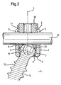
- the bone anchoring device comprises a receiving part 1 which is substantially cylindrical and has a first end 2 and a second end 3 opposite to the first end.
- the two ends extend perpendicular to a longitudinal axis 4.
- a bore 5 is provided which extends from the first end 2 to a predetermined distance from the second end 3.
- an opening 6 is provided at the second end 3 the diameter of which is smaller than the diameter of the bore 5.
- the coaxial bore 5 tapers towards the opening 6 in a section 7 which can be for example spherically or conically shaped.
- the receiving part 1 further has a U-shaped recess 8 which starts from the first end 2 and extends in the direction of the second end 3 to a predetermined distance from said second end 3.
- a U-shaped recess 8 By means of the U-shaped recess 8 two free legs 9, 10 are formed extending towards the first end 2.
- Adjacent to the first end 2, the receiving part 1 comprises an internal thread 11 on said legs 9, 10.
- the U-shaped recess 8 serves for receiving a rod 12 by means of which several bone anchoring devices are to be connected.
- the bone anchoring device further comprises a bone anchoring element 13 comprising a shank 14 with a bone thread and a head 15 at one end.
- the head 15 has two sections 16a, 16b which are located opposite to each other and which have a spherical outer surface with the center M of the sphere lying in the center of the head 15. Between the two opposite spherical surfaces 16a, 16b the head 15 comprises two cylindrically-shaped surfaces 17a, 17b with the cylinder axis C being perpendicular to the longitudinal axis L of the bone anchoring element 13 and extending through the center M of the head.
- the head 15 comprises a flat surface 18.
- a recess 19 for engagement with screwing-in tool is provided in the flat surface 18.
- the cylinder radius of the cylindrically-shaped surfaces 17a and 17b is smaller than the radius of the spherical surfaces 16a, 16b.
- the diameter of the threaded section 14 is smaller than the diameter of the opening 6 of the receiving part so that the anchoring element 13 can be inserted from the first end 2 in the receiving part 1, the threaded section 14 being guided through the lower opening 6 until the spherical surfaces 16a, 16b come into contact with the tapering section 7 of the receiving part 1.
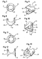
- the bone anchoring device further comprises a pressure element 20 for acting onto the head 15 and to limit a pivoting movement of the head 15 in the receiving part 1.
- the pressure element 20 is substantially cylindrically-shaped and comprises a first end 21 and a second end 22.
- the outer diameter of the pressure element 20 is slightly smaller than the inner diameter of the bore 5 of the receiving part 1 so that the pressure element 20 can be inserted into the receiving part 1 and can slide within the bore 5.
- Adjacent to the first end 21 the pressure element 20 comprises a cylindrical segment-shaped recess 23 the size of which is such that the rod 12 fits to the recess 23.
- Adjacent to the second end 22 the pressure element 20 comprises a second cylindrical segment-shaped recess 24 the cylinder axis of which is perpendicular to the cylinder axis of the first cylindrical segment-shaped recess 23.
- the radius of the cylinder segment of the second cylindrical segment-shaped recess 24 corresponds essentially to the radius of the cylindrically-shaped surfaces 17a, 17b of the head 15.
- the width W of the second cylindrical segment-shaped recess 24 corresponds to the width of the cylindrical surfaces 17a, 17b of the head 15 such that the cylindrical segment-shaped recess 24 covers at least partly the surfaces 17a, 17b when the anchoring element 13 and the pressure element are inserted in the receiving part 1.
- the pressure element 20 further comprises adjacent to the second end 22 two opposite spherical recesses 25a, 25b extending on both sides of the second cylindrical segment-shaped recess 24 and having a diameter which is, for example, equal or larger than the diameter of the opposing spherical surfaces 16a, 16b of the head 15 so that, as can be seen in Figs. 12a, 11b and 13 the spherical surfaces 16a, 16b of the head 15 are not covered by the pressure element 20.
- the pressure element 20 comprises crimp bores 26 on its outer surface which are located preferably opposite to each other at the sides having the recesses 25a, 25b and which engage with corresponding crimp bores 27 on the legs in the receiving part 1, respectively.
- the crimp bores 26, 27 serve for a loose pre-assembly of the pressure element 20 within the receiving part so that the pressure element 20 cannot fall out. In this way also the pivoting plane of the anchoring element relative to the receiving part is pre-defined.
- the pressure element 20 has a coaxial bore 28 for allowing access for a screwing-in tool to the recess 19 in the head 15.
- Figs. 12 and 13 a modified embodiment of the pressure element is shown.
- the pressure element 20' differs from the pressure element shown in Figs. 7 to 11 in that the second cylindrical recess 24' is aligned with respect to the first cylindrical recess 23 in such a way that the cylinder axes are parallel.
- the axis of rotation for the pivoting motion of the anchoring element is rotated by 90° compared to the case in which the pressure element shown in Figs. 7 to 11 is used.
- the bone anchoring device also comprises an inner screw 30 that can be screwed between the legs 9, 10 to fix the rod 12 and to exert a pressure onto the head 15 via the rod 12.
- the whole device is made of a biocompatible material, for example titanium.
- the anchoring element 13 is inserted into the receiving part 1 by guiding the threaded shaft 14 through the opening 6 at the second end 3 of the receiving part until the head 15 rests against the section 7 adjacent to the opening 6. Then, the pressure element 20 is inserted into the receiving part 1 with its second end 22 facing the head and is held loosely by the cooperating crimp bores 26, 27 in a position in which the recess 23 of the pressure element is coaxial with the recess 8 of the receiving part 1.
- the cylindrical surfaces 17a, 17b of the head 15 are covered at least partly with the cylindrical surface of the recess 24 of the pressure element. In this manner pre-assembled, the anchoring element 13 is screwed into the bone.
- the anchoring element 13 is still pivotable with respect to the receiving part 1, however, the angular range of pivoting is limited and lies within a plane P which contains the longitudinal axis 4 of the receiving part and forms the plane of mirror symmetry of the receiving part 1.
- the plane P is the sectional plane of the section shown in Fig. 2 . Pivoting in a single plane is accomplished by the pressure element 20 acting onto the head 15 without exerting pressure onto the head 15 only by the cooperation of the surfaces 17a, 17b with the second cylindrical segment-shaped recess 24 which allows a pivoting motion around the cylinder axis C but prevents pivoting in another direction.
- the first bone anchoring device 1 comprises the pressure element 20 shown in Figs. 7 to 11 .
- the axis of rotation of the anchoring element 13 is perpendicular to the rod axis A which allows an adjustment in a plane defined by the longitudinal axis 4 of the receiving part 1 and the rod axis A.
- the second bone anchoring element 50' comprises a pressure element 20' as shown in Figs. 12 and 13 .
- the axis of rotation of the bone anchoring element 13 is parallel to the rod axis A which allows an adjustment of the anchoring element 13 in a single plane which is perpendicular to the rod axis A and includes the longitudinal axis 4 of the receiving part.
- the bone anchoring device allows an adjustment in a single plane or, in other words, a rotation around one rotational axis. Therefore, the anchoring element is connected to the receiving part in a monoplanar manner.
- the bone anchoring device is more stable than a polyaxial bone anchoring device which allows a pivoting in a range of 360° around the longitudinal axis. It has an improved resistance to loads and allows a positional adjustment of the receiving part which is sufficient for specific clinical applications.
- By selecting the appropriate pressure element it is possible to assemble a bone anchoring device which can be adjusted in a desired plane relative to the rod according to the actual anatomical requirements.
- the invention is not limited to the embodiment shown above. Modifications are conceivable. Any orientation of the two cylinder axes of the first and the second cylindrical recesses of the pressure element with respect to each other is possible.
- the cylinder segment-shaped recess 23 of the pressure element can be omitted. That means, the first end 21 of the pressure element can have a flat surface. In this case, the pressure element can be oriented within the receiving part such that the second cylinder segment-shaped recess is aligned in any desired direction.
- the surfaces 16a, 16b of the head 15 do not need to have a spherical shape. They can also be flat.
- the single plane in which the anchoring element can be pivoted need not include the longitudinal axis. It can also extend in parallel to the longitudinal axis.
- the receiving part can have an asymmetric edge at the opening 6 to enable a larger pivot angle on one side of the longitudinal axis that on the other side.
- the asymmetry in the pivot angle can be achieved also by other means.
- the pressure is exerted via the rod 12 onto the pressure element 20 which itself presses onto the head. It is, however, possible to separate the locking of the head 15 via the pressure element 20 from the locking of the rod 12.
- the recess 23 in the pressure element 20 comprises upwardly extending legs extending above the inserted rod 12 so that it is possible to press separately onto these legs via separate inner screw encompassing the inner screw 30 which presses onto the rod.
- a construction is possible in which the head is inserted into the receiving part 1 from the second end 3.
- the opening 6 must be large enough to introduce the head and means must be provided to prevent falling-out of the head.
- any other bone anchoring means is conceivable, such as nails or hooks.
- the bone anchoring device needs not to be pre-assembled before use in surgery. It can also be assembled during surgery.
Landscapes
- Health & Medical Sciences (AREA)
- Orthopedic Medicine & Surgery (AREA)
- Life Sciences & Earth Sciences (AREA)
- Surgery (AREA)
- Neurology (AREA)
- Heart & Thoracic Surgery (AREA)
- Engineering & Computer Science (AREA)
- Biomedical Technology (AREA)
- Nuclear Medicine, Radiotherapy & Molecular Imaging (AREA)
- Medical Informatics (AREA)
- Molecular Biology (AREA)
- Animal Behavior & Ethology (AREA)
- General Health & Medical Sciences (AREA)
- Public Health (AREA)
- Veterinary Medicine (AREA)
- Surgical Instruments (AREA)
- Prostheses (AREA)
Priority Applications (11)
| Application Number | Priority Date | Filing Date | Title |
|---|---|---|---|
| EP05022263A EP1774919B1 (en) | 2005-10-12 | 2005-10-12 | Poly-axial screw pivotable in a single plane |
| DE602005009202T DE602005009202D1 (de) | 2005-10-12 | 2005-10-12 | In nur einer Ebene schwenkbare Polyaxialschraube |
| ES05022263T ES2313182T3 (es) | 2005-10-12 | 2005-10-12 | Tormillo poliaxial pivotable en un solo plano. |
| TW095137002A TWI379657B (en) | 2005-10-12 | 2006-10-05 | Bone anchoring device |
| CN2006101416575A CN1965769B (zh) | 2005-10-12 | 2006-10-09 | 骨锚固装置 |
| KR1020060097933A KR101267581B1 (ko) | 2005-10-12 | 2006-10-09 | 뼈 고정장치 |
| JP2006277512A JP4994773B2 (ja) | 2005-10-12 | 2006-10-11 | 骨固定装置 |
| US11/548,856 US7749258B2 (en) | 2005-10-12 | 2006-10-12 | Bone anchoring device |
| US12/791,509 US8048133B2 (en) | 2005-10-12 | 2010-06-01 | Bone anchoring device |
| US13/245,361 US8506611B2 (en) | 2005-10-12 | 2011-09-26 | Bone anchoring device |
| US13/951,270 US9078715B2 (en) | 2005-10-12 | 2013-07-25 | Bone anchoring device |
Applications Claiming Priority (1)
| Application Number | Priority Date | Filing Date | Title |
|---|---|---|---|
| EP05022263A EP1774919B1 (en) | 2005-10-12 | 2005-10-12 | Poly-axial screw pivotable in a single plane |
Publications (2)
| Publication Number | Publication Date |
|---|---|
| EP1774919A1 EP1774919A1 (en) | 2007-04-18 |
| EP1774919B1 true EP1774919B1 (en) | 2008-08-20 |
Family
ID=35739310
Family Applications (1)
| Application Number | Title | Priority Date | Filing Date |
|---|---|---|---|
| EP05022263A Active EP1774919B1 (en) | 2005-10-12 | 2005-10-12 | Poly-axial screw pivotable in a single plane |
Country Status (8)
| Country | Link |
|---|---|
| US (4) | US7749258B2 (zh) |
| EP (1) | EP1774919B1 (zh) |
| JP (1) | JP4994773B2 (zh) |
| KR (1) | KR101267581B1 (zh) |
| CN (1) | CN1965769B (zh) |
| DE (1) | DE602005009202D1 (zh) |
| ES (1) | ES2313182T3 (zh) |
| TW (1) | TWI379657B (zh) |
Cited By (7)
| Publication number | Priority date | Publication date | Assignee | Title |
|---|---|---|---|---|
| US8348952B2 (en) | 2006-01-26 | 2013-01-08 | Depuy International Ltd. | System and method for cooling a spinal correction device comprising a shape memory material for corrective spinal surgery |
| US8425563B2 (en) | 2006-01-13 | 2013-04-23 | Depuy International Ltd. | Spinal rod support kit |
| US9724145B2 (en) | 2013-03-14 | 2017-08-08 | Medos International Sarl | Bone anchor assemblies with multiple component bottom loading bone anchors |
| US10786284B2 (en) | 2012-09-28 | 2020-09-29 | Medos International Sarl | Bone anchor assemblies |
| US10987145B2 (en) | 2008-02-04 | 2021-04-27 | Medos International Sarl | Methods for correction of spinal deformities |
| US10987138B2 (en) | 2013-03-14 | 2021-04-27 | Medos International Sari | Locking compression members for use with bone anchor assemblies and methods |
| US11311318B2 (en) | 2013-03-14 | 2022-04-26 | DePuy Synthes Products, Inc. | Bone anchor assemblies and methods with improved locking |
Families Citing this family (148)
| Publication number | Priority date | Publication date | Assignee | Title |
|---|---|---|---|---|
| US7833250B2 (en) | 2004-11-10 | 2010-11-16 | Jackson Roger P | Polyaxial bone screw with helically wound capture connection |
| US8353932B2 (en) | 2005-09-30 | 2013-01-15 | Jackson Roger P | Polyaxial bone anchor assembly with one-piece closure, pressure insert and plastic elongate member |
| US7862587B2 (en) | 2004-02-27 | 2011-01-04 | Jackson Roger P | Dynamic stabilization assemblies, tool set and method |
| US10258382B2 (en) | 2007-01-18 | 2019-04-16 | Roger P. Jackson | Rod-cord dynamic connection assemblies with slidable bone anchor attachment members along the cord |
| US10729469B2 (en) | 2006-01-09 | 2020-08-04 | Roger P. Jackson | Flexible spinal stabilization assembly with spacer having off-axis core member |
| US8292926B2 (en) | 2005-09-30 | 2012-10-23 | Jackson Roger P | Dynamic stabilization connecting member with elastic core and outer sleeve |
| WO2006052796A2 (en) | 2004-11-10 | 2006-05-18 | Jackson Roger P | Helical guide and advancement flange with break-off extensions |
| US8876868B2 (en) | 2002-09-06 | 2014-11-04 | Roger P. Jackson | Helical guide and advancement flange with radially loaded lip |
| US6716214B1 (en) | 2003-06-18 | 2004-04-06 | Roger P. Jackson | Polyaxial bone screw with spline capture connection |
| US7621918B2 (en) | 2004-11-23 | 2009-11-24 | Jackson Roger P | Spinal fixation tool set and method |
| US7377923B2 (en) | 2003-05-22 | 2008-05-27 | Alphatec Spine, Inc. | Variable angle spinal screw assembly |
| US8137386B2 (en) | 2003-08-28 | 2012-03-20 | Jackson Roger P | Polyaxial bone screw apparatus |
| US8398682B2 (en) | 2003-06-18 | 2013-03-19 | Roger P. Jackson | Polyaxial bone screw assembly |
| US8377102B2 (en) | 2003-06-18 | 2013-02-19 | Roger P. Jackson | Polyaxial bone anchor with spline capture connection and lower pressure insert |
| US7967850B2 (en) | 2003-06-18 | 2011-06-28 | Jackson Roger P | Polyaxial bone anchor with helical capture connection, insert and dual locking assembly |
| US8814911B2 (en) | 2003-06-18 | 2014-08-26 | Roger P. Jackson | Polyaxial bone screw with cam connection and lock and release insert |
| US7776067B2 (en) | 2005-05-27 | 2010-08-17 | Jackson Roger P | Polyaxial bone screw with shank articulation pressure insert and method |
| US8936623B2 (en) | 2003-06-18 | 2015-01-20 | Roger P. Jackson | Polyaxial bone screw assembly |
| US8257398B2 (en) | 2003-06-18 | 2012-09-04 | Jackson Roger P | Polyaxial bone screw with cam capture |
| US7766915B2 (en) | 2004-02-27 | 2010-08-03 | Jackson Roger P | Dynamic fixation assemblies with inner core and outer coil-like member |
| US11419642B2 (en) | 2003-12-16 | 2022-08-23 | Medos International Sarl | Percutaneous access devices and bone anchor assemblies |
| US7527638B2 (en) | 2003-12-16 | 2009-05-05 | Depuy Spine, Inc. | Methods and devices for minimally invasive spinal fixation element placement |
| US7179261B2 (en) | 2003-12-16 | 2007-02-20 | Depuy Spine, Inc. | Percutaneous access devices and bone anchor assemblies |
| US7678137B2 (en) | 2004-01-13 | 2010-03-16 | Life Spine, Inc. | Pedicle screw constructs for spine fixation systems |
| US8152810B2 (en) | 2004-11-23 | 2012-04-10 | Jackson Roger P | Spinal fixation tool set and method |
| EP1720468A4 (en) | 2004-02-27 | 2010-01-27 | Roger P Jackson | ORTHOPEDIC IMPLANT ROD REDUCTION INSTRUMENT ASSEMBLY AND METHOD THEREOF |
| US7160300B2 (en) | 2004-02-27 | 2007-01-09 | Jackson Roger P | Orthopedic implant rod reduction tool set and method |
| US11241261B2 (en) | 2005-09-30 | 2022-02-08 | Roger P Jackson | Apparatus and method for soft spinal stabilization using a tensionable cord and releasable end structure |
| US7901435B2 (en) * | 2004-05-28 | 2011-03-08 | Depuy Spine, Inc. | Anchoring systems and methods for correcting spinal deformities |
| US20060058788A1 (en) * | 2004-08-27 | 2006-03-16 | Hammer Michael A | Multi-axial connection system |
| US8951290B2 (en) | 2004-08-27 | 2015-02-10 | Blackstone Medical, Inc. | Multi-axial connection system |
| US7651502B2 (en) | 2004-09-24 | 2010-01-26 | Jackson Roger P | Spinal fixation tool set and method for rod reduction and fastener insertion |
| US8926672B2 (en) | 2004-11-10 | 2015-01-06 | Roger P. Jackson | Splay control closure for open bone anchor |
| US7875065B2 (en) | 2004-11-23 | 2011-01-25 | Jackson Roger P | Polyaxial bone screw with multi-part shank retainer and pressure insert |
| WO2006057837A1 (en) | 2004-11-23 | 2006-06-01 | Jackson Roger P | Spinal fixation tool attachment structure |
| US8308782B2 (en) | 2004-11-23 | 2012-11-13 | Jackson Roger P | Bone anchors with longitudinal connecting member engaging inserts and closures for fixation and optional angulation |
| US9980753B2 (en) | 2009-06-15 | 2018-05-29 | Roger P Jackson | pivotal anchor with snap-in-place insert having rotation blocking extensions |
| US9168069B2 (en) | 2009-06-15 | 2015-10-27 | Roger P. Jackson | Polyaxial bone anchor with pop-on shank and winged insert with lower skirt for engaging a friction fit retainer |
| US8444681B2 (en) | 2009-06-15 | 2013-05-21 | Roger P. Jackson | Polyaxial bone anchor with pop-on shank, friction fit retainer and winged insert |
| US9216041B2 (en) | 2009-06-15 | 2015-12-22 | Roger P. Jackson | Spinal connecting members with tensioned cords and rigid sleeves for engaging compression inserts |
| US10076361B2 (en) | 2005-02-22 | 2018-09-18 | Roger P. Jackson | Polyaxial bone screw with spherical capture, compression and alignment and retention structures |
| US7901437B2 (en) | 2007-01-26 | 2011-03-08 | Jackson Roger P | Dynamic stabilization member with molded connection |
| US7955358B2 (en) | 2005-09-19 | 2011-06-07 | Albert Todd J | Bone screw apparatus, system and method |
| US8105368B2 (en) | 2005-09-30 | 2012-01-31 | Jackson Roger P | Dynamic stabilization connecting member with slitted core and outer sleeve |
| GB0521582D0 (en) | 2005-10-22 | 2005-11-30 | Depuy Int Ltd | An implant for supporting a spinal column |
| DE602006009682D1 (de) * | 2006-11-17 | 2009-11-19 | Biedermann Motech Gmbh | Knochenverankerungsvorrichtung |
| JP2010512178A (ja) | 2006-12-08 | 2010-04-22 | ロジャー・ピー・ジャクソン | 動的脊椎インプラントのためのツールシステム |
| EP2117451A1 (en) * | 2006-12-29 | 2009-11-18 | Zimmer Spine Austin, Inc. | Spinal stabilization systems and methods |
| US8636783B2 (en) * | 2006-12-29 | 2014-01-28 | Zimmer Spine, Inc. | Spinal stabilization systems and methods |
| US8366745B2 (en) | 2007-05-01 | 2013-02-05 | Jackson Roger P | Dynamic stabilization assembly having pre-compressed spacers with differential displacements |
| US8475498B2 (en) | 2007-01-18 | 2013-07-02 | Roger P. Jackson | Dynamic stabilization connecting member with cord connection |
| US8167912B2 (en) | 2007-02-27 | 2012-05-01 | The Center for Orthopedic Research and Education, Inc | Modular pedicle screw system |
| US7967849B2 (en) * | 2007-04-06 | 2011-06-28 | Warsaw Orthopedic, Inc. | Adjustable multi-axial spinal coupling assemblies |
| US10383660B2 (en) | 2007-05-01 | 2019-08-20 | Roger P. Jackson | Soft stabilization assemblies with pretensioned cords |
| US7942911B2 (en) | 2007-05-16 | 2011-05-17 | Ortho Innovations, Llc | Polyaxial bone screw |
| US7942910B2 (en) | 2007-05-16 | 2011-05-17 | Ortho Innovations, Llc | Polyaxial bone screw |
| US8197518B2 (en) | 2007-05-16 | 2012-06-12 | Ortho Innovations, Llc | Thread-thru polyaxial pedicle screw system |
| US7951173B2 (en) | 2007-05-16 | 2011-05-31 | Ortho Innovations, Llc | Pedicle screw implant system |
| US7947065B2 (en) | 2008-11-14 | 2011-05-24 | Ortho Innovations, Llc | Locking polyaxial ball and socket fastener |
| US7942909B2 (en) | 2009-08-13 | 2011-05-17 | Ortho Innovations, Llc | Thread-thru polyaxial pedicle screw system |
| US8162987B2 (en) * | 2007-06-05 | 2012-04-24 | Spartek Medical, Inc. | Modular spine treatment kit for dynamic stabilization and motion preservation of the spine |
| EP2016916B1 (en) * | 2007-07-20 | 2010-06-30 | BIEDERMANN MOTECH GmbH | Bone anchoring device |
| FR2920959B1 (fr) * | 2007-09-17 | 2010-09-10 | Clariance | Dispositif d'ancrage vertebral. |
| US8038701B2 (en) * | 2007-10-22 | 2011-10-18 | K2M, Inc. | Uni-planar, taper lock bone screw |
| GB0720762D0 (en) | 2007-10-24 | 2007-12-05 | Depuy Spine Sorl | Assembly for orthopaedic surgery |
| US7857835B2 (en) | 2008-02-22 | 2010-12-28 | Depuy Spine, Inc. | Method and system for trans-lamina spinal fixation |
| WO2009124196A2 (en) * | 2008-04-03 | 2009-10-08 | Life Spine, Inc. | Top loading polyaxial spine screw assembly with one step lockup |
| EP2334262B1 (en) | 2008-06-27 | 2015-02-25 | K2M, Inc. | System for performing spinal surgery |
| EP2303162B1 (en) * | 2008-07-25 | 2011-12-14 | Hays Saglik Urunleri Ic Ve Dis Ticaret Hayvancilik Limited Sirketi | Posterior dynamic screw |
| AU2010260521C1 (en) | 2008-08-01 | 2013-08-01 | Roger P. Jackson | Longitudinal connecting member with sleeved tensioned cords |
| ES2394670T3 (es) | 2008-10-08 | 2013-02-04 | Biedermann Technologies Gmbh & Co. Kg | Dispositivo de implante alargado y dispositivo de estabilización vertebral |
| US8075603B2 (en) * | 2008-11-14 | 2011-12-13 | Ortho Innovations, Llc | Locking polyaxial ball and socket fastener |
| EP2221013B1 (en) | 2009-02-20 | 2015-08-05 | Biedermann Technologies GmbH & Co. KG | Receiving part for receiving a rod for coupling the rod to a bone anchoring element and a bone anchoring device with such a receiving part |
| US8998959B2 (en) | 2009-06-15 | 2015-04-07 | Roger P Jackson | Polyaxial bone anchors with pop-on shank, fully constrained friction fit retainer and lock and release insert |
| US11229457B2 (en) | 2009-06-15 | 2022-01-25 | Roger P. Jackson | Pivotal bone anchor assembly with insert tool deployment |
| WO2013043218A1 (en) | 2009-06-15 | 2013-03-28 | Jackson Roger P | Polyaxial bone anchor with pop-on shank and winged insert with friction fit compressive collet |
| US9668771B2 (en) | 2009-06-15 | 2017-06-06 | Roger P Jackson | Soft stabilization assemblies with off-set connector |
| EP2753252A1 (en) | 2009-06-15 | 2014-07-16 | Jackson, Roger P. | Polyaxial bone anchor with pop-on shank and friction fit retainer with low profile edge lock |
| CA2774471A1 (en) | 2009-10-05 | 2011-04-14 | James L. Surber | Polyaxial bone anchor with non-pivotable retainer and pop-on shank, some with friction fit |
| US8430917B2 (en) * | 2009-10-30 | 2013-04-30 | Warsaw Orthopedic, Inc. | Bone engaging implant with adjustment saddle |
| US9044272B2 (en) | 2009-11-09 | 2015-06-02 | Ebi, Llc | Multiplanar bone anchor system |
| US8449578B2 (en) * | 2009-11-09 | 2013-05-28 | Ebi, Llc | Multiplanar bone anchor system |
| US8986349B1 (en) * | 2009-11-11 | 2015-03-24 | Nuvasive, Inc. | Systems and methods for correcting spinal deformities |
| US8419778B2 (en) * | 2010-01-15 | 2013-04-16 | Ebi, Llc | Uniplanar bone anchor system |
| US8647370B2 (en) | 2010-01-15 | 2014-02-11 | Ebi, Llc | Uniplanar bone anchor system |
| US20110196430A1 (en) * | 2010-02-10 | 2011-08-11 | Walsh David A | Spinal fixation assembly with intermediate element |
| US9393048B2 (en) | 2010-02-23 | 2016-07-19 | K2M, Inc. | Polyaxial bonescrew assembly |
| WO2011127065A1 (en) * | 2010-04-06 | 2011-10-13 | Seaspine, Inc. | System and methods for correcting spinal deformities |
| DE102010028423B4 (de) * | 2010-04-30 | 2016-04-14 | Kilian Kraus | Pedikelschraube und Vorrichtung zur Stabilisierung der Wirbelsäule |
| EP2605716B1 (en) | 2010-08-20 | 2021-04-21 | K2M, Inc. | Spinal fixation system |
| AU2014200455B2 (en) * | 2010-08-20 | 2014-12-18 | K2M, Inc. | Spinal Fixation System |
| US9393049B2 (en) | 2010-08-20 | 2016-07-19 | K2M, Inc. | Spinal fixation system |
| WO2012030712A1 (en) | 2010-08-30 | 2012-03-08 | Zimmer Spine, Inc. | Polyaxial pedicle screw |
| BR112013005465A2 (pt) | 2010-09-08 | 2019-09-24 | P Jackson Roger | elemento de conexão em um conjunto de implante médico tendo pelo menos duas estruturas de fixação de osso cooperando com um elemento de conexão longitudinal dinâmico |
| WO2012060868A1 (en) | 2010-11-02 | 2012-05-10 | Jackson Roger P | Polyaxial bone anchor with pop-on shank and pivotable retainer |
| EP2468199B1 (en) * | 2010-12-27 | 2013-08-07 | Biedermann Technologies GmbH & Co. KG | Polyaxial bone anchoring device |
| CN102551856B (zh) * | 2011-01-24 | 2014-07-09 | 上海锐植医疗器械有限公司 | 自旋转撑开脊柱创伤内固定系统 |
| CN102068304B (zh) * | 2011-01-26 | 2013-01-02 | 邱勇 | 一种椎弓根钉 |
| CN102090920A (zh) * | 2011-03-21 | 2011-06-15 | 丁亮华 | 万向微动椎弓根钉 |
| JP5865479B2 (ja) | 2011-03-24 | 2016-02-17 | ロジャー・ピー・ジャクソン | 複合関節とポップ装着式シャンクとを有する多軸の骨アンカー |
| US9072551B2 (en) * | 2011-06-09 | 2015-07-07 | Christel Paroth | Surgical instrument |
| DE102011050996A1 (de) * | 2011-06-09 | 2012-12-13 | Zbigniew Combrowski | Chirurgisches Instrument |
| US9005249B2 (en) | 2011-07-11 | 2015-04-14 | Life Spine, Inc. | Spinal rod connector assembly |
| US11103286B2 (en) * | 2011-07-15 | 2021-08-31 | Globus Medical, Inc. | Orthopedic fixation devices and methods of installation thereof |
| US9295501B2 (en) | 2011-08-02 | 2016-03-29 | Blackstone Medical, Inc. | Bayonet counter-torque wrench |
| ES2418604T3 (es) * | 2011-08-18 | 2013-08-14 | Biedermann Technologies Gmbh & Co. Kg | Dispositivo de anclaje óseo poliaxial |
| EP2604204B1 (en) | 2011-12-13 | 2014-10-01 | Biedermann Technologies GmbH & Co. KG | Monoplanar bone anchoring device with selectable pivot plane |
| EP2606841B1 (en) * | 2011-12-23 | 2016-03-09 | Biedermann Technologies GmbH & Co. KG | Polyaxial bone anchoring device |
| US8911479B2 (en) | 2012-01-10 | 2014-12-16 | Roger P. Jackson | Multi-start closures for open implants |
| CN102641148A (zh) * | 2012-04-16 | 2012-08-22 | 黄孟锋 | 骨骼固定装置 |
| ES2696676T3 (es) | 2012-09-04 | 2019-01-17 | Trigueros Ignacio Sanpera | Sistema para una corrección global tridimensional de las curvaturas de la columna |
| US8911478B2 (en) | 2012-11-21 | 2014-12-16 | Roger P. Jackson | Splay control closure for open bone anchor |
| CN103070725A (zh) * | 2013-01-14 | 2013-05-01 | 北京市富乐科技开发有限公司 | 微创加长臂椎弓根钉 |
| US10058354B2 (en) | 2013-01-28 | 2018-08-28 | Roger P. Jackson | Pivotal bone anchor assembly with frictional shank head seating surfaces |
| EP2764840B1 (en) | 2013-02-11 | 2017-05-03 | Biedermann Technologies GmbH & Co. KG | Coupling assembly for coupling a rod to a bone anchoring element and bone anchoring device with such a coupling assembly |
| US8852239B2 (en) | 2013-02-15 | 2014-10-07 | Roger P Jackson | Sagittal angle screw with integral shank and receiver |
| US9775660B2 (en) | 2013-03-14 | 2017-10-03 | DePuy Synthes Products, Inc. | Bottom-loading bone anchor assemblies and methods |
| US20140277153A1 (en) | 2013-03-14 | 2014-09-18 | DePuy Synthes Products, LLC | Bone Anchor Assemblies and Methods With Improved Locking |
| EP3673844A1 (en) | 2013-04-12 | 2020-07-01 | Alphatec Spine, Inc. | Uniplanar screw assembly |
| US9453526B2 (en) | 2013-04-30 | 2016-09-27 | Degen Medical, Inc. | Bottom-loading anchor assembly |
| US9526529B2 (en) | 2013-09-25 | 2016-12-27 | Blackstone Medical, Inc. | Bone screw systems with pressure caps having biasing members |
| DE102013110796A1 (de) | 2013-09-30 | 2015-04-02 | Z-Medical Gmbh & Co. Kg | Chirurgisches Instrument |
| US9480501B2 (en) * | 2013-10-21 | 2016-11-01 | Blackstone Medical, Inc. | Modular pedicle screw |
| US9566092B2 (en) | 2013-10-29 | 2017-02-14 | Roger P. Jackson | Cervical bone anchor with collet retainer and outer locking sleeve |
| US20160287293A1 (en) * | 2013-11-22 | 2016-10-06 | Spinal Balance, Inc. | Poly-Axial Pedicle Screw Assembly and Packaging Therefor |
| US9980758B2 (en) | 2013-11-27 | 2018-05-29 | Blackstone Medical, Inc. | Minimally invasive counter-torque wrench system |
| US9717533B2 (en) | 2013-12-12 | 2017-08-01 | Roger P. Jackson | Bone anchor closure pivot-splay control flange form guide and advancement structure |
| US9451993B2 (en) | 2014-01-09 | 2016-09-27 | Roger P. Jackson | Bi-radial pop-on cervical bone anchor |
| EP2893890B1 (en) * | 2014-01-13 | 2016-11-02 | Biedermann Technologies GmbH & Co. KG | Coupling assembly for coupling a rod to a bone anchoring element, and polyaxial bone anchoring device |
| US10918419B2 (en) | 2014-04-01 | 2021-02-16 | K2M, Inc. | Spinal fixation device |
| US9549765B2 (en) | 2014-04-03 | 2017-01-24 | Zimmer Spine, Inc. | Uniplanar bone screw |
| EP2939622A1 (en) | 2014-04-30 | 2015-11-04 | Sanpera Trigueros, Ignacio | System for correction of the spine curvatures |
| US9597119B2 (en) | 2014-06-04 | 2017-03-21 | Roger P. Jackson | Polyaxial bone anchor with polymer sleeve |
| US10064658B2 (en) | 2014-06-04 | 2018-09-04 | Roger P. Jackson | Polyaxial bone anchor with insert guides |
| FR3027209B1 (fr) * | 2014-10-20 | 2016-11-25 | Safe Orthopaedics | Dispositif d'ancrage vertebral multiaxial pour le redressement d'une vertebre |
| CN106037994B (zh) * | 2016-07-08 | 2018-09-18 | 北京大学人民医院 | 髋骨修复体 |
| CN106073948B (zh) * | 2016-07-08 | 2018-02-02 | 北京大学人民医院 | 髂骨修复体 |
| US10575878B2 (en) * | 2016-07-21 | 2020-03-03 | Warsaw Orthopedic, Inc. | Spinal implant system and methods of use |
| CA3043217A1 (en) | 2016-11-18 | 2018-05-24 | Javier Garcia-Bengochea | Implants and instruments for enhancing vertebral alignment and sagittal balance |
| WO2018186887A1 (en) * | 2017-04-07 | 2018-10-11 | Facet-Link Inc. | Spinal fixation element and stabilization system |
| US10610265B1 (en) | 2017-07-31 | 2020-04-07 | K2M, Inc. | Polyaxial bone screw with increased angulation |
| US10743918B2 (en) * | 2018-06-27 | 2020-08-18 | Texas Scottish Rite Hospital For Children | External fixation connection rod with female attachment |
| CN117379157A (zh) | 2018-11-16 | 2024-01-12 | 南十字专利私人有限公司 | 单轴椎弓根螺钉组件 |
| WO2020183337A1 (en) * | 2019-03-12 | 2020-09-17 | Carbofix In Orthopedics Llc | Composite material spinal implant |
| DE102019116368A1 (de) | 2019-06-17 | 2020-12-17 | Aesculap Ag | Teilweise blockierte Pedikelschraube |
| DE102019116374A1 (de) | 2019-06-17 | 2020-12-17 | Aesculap Ag | Teilweise blockierte Pedikelschraube II |
| US11311316B2 (en) * | 2020-09-04 | 2022-04-26 | Warsaw Orthopedic, Inc. | Spinal implant system and methods of use |
| US11751915B2 (en) | 2021-07-09 | 2023-09-12 | Roger P. Jackson | Modular spinal fixation system with bottom-loaded universal shank heads |
Family Cites Families (19)
| Publication number | Priority date | Publication date | Assignee | Title |
|---|---|---|---|---|
| US4500586A (en) * | 1981-01-29 | 1985-02-19 | Bussey Harry Jun | Billowed filling elements for packaging |
| FR2633177B1 (fr) | 1988-06-24 | 1991-03-08 | Fabrication Materiel Orthopedi | Implant pour dispositif d'osteosynthese rachidienne, notamment en traumatologie |
| US5102412A (en) | 1990-06-19 | 1992-04-07 | Chaim Rogozinski | System for instrumentation of the spine in the treatment of spinal deformities |
| US5595811A (en) * | 1992-01-31 | 1997-01-21 | Stout, Jr.; William A. | Packaging material |
| DE4307576C1 (de) | 1993-03-10 | 1994-04-21 | Biedermann Motech Gmbh | Knochenschraube |
| DE4425357C2 (de) * | 1994-07-18 | 1996-07-04 | Harms Juergen | Verankerungselement |
| CN1142746C (zh) * | 1996-12-12 | 2004-03-24 | 库尔斯恩蒂斯股份公司 | 用于连接纵向支架和花托形螺钉的装置 |
| US6485494B1 (en) * | 1996-12-20 | 2002-11-26 | Thomas T. Haider | Pedicle screw system for osteosynthesis |
| IL124529A (en) * | 1997-05-20 | 2001-08-08 | Akiva Raphael Katz | Pedicle screw assembly |
| US6467996B1 (en) * | 1999-04-08 | 2002-10-22 | Rapac, Inc. | Polystyrene beads for drainage fields |
| US6254602B1 (en) | 1999-05-28 | 2001-07-03 | Sdgi Holdings, Inc. | Advanced coupling device using shape-memory technology |
| DE10055888C1 (de) | 2000-11-10 | 2002-04-25 | Biedermann Motech Gmbh | Knochenschraube |
| US6800079B2 (en) * | 2002-03-15 | 2004-10-05 | Lock-N-Stitch, Inc. | Orthopedic stabilization device and method |
| WO2003032863A2 (en) | 2001-10-15 | 2003-04-24 | Reed Gary J | Orthopedic stabilization device and method |
| DE20207851U1 (de) | 2002-05-21 | 2002-10-10 | Metz Stavenhagen Peter | Verankerungselement zur Befestigung eines Stabes einer Vorrichtung zum Einrichten einer menschlichen oder tierischen Wirbelsäule an einem Wirbelknochen |
| EP1673024B1 (en) * | 2003-08-20 | 2014-04-09 | Warsaw Orthopedic, Inc. | Multi-axial orthopedic device and system, e.g. for spinal surgery |
| US20050159750A1 (en) * | 2003-12-30 | 2005-07-21 | Thomas Doherty | Bone anchor assemblies and methods of manufacturing bone anchor assemblies |
| US7951172B2 (en) * | 2005-03-04 | 2011-05-31 | Depuy Spine Sarl | Constrained motion bone screw assembly |
| WO2008128156A1 (en) * | 2007-04-13 | 2008-10-23 | Fagerdala Usa, Inc. | Lighweight aggregate unit and method of manufacture |
-
2005
- 2005-10-12 ES ES05022263T patent/ES2313182T3/es active Active
- 2005-10-12 DE DE602005009202T patent/DE602005009202D1/de active Active
- 2005-10-12 EP EP05022263A patent/EP1774919B1/en active Active
-
2006
- 2006-10-05 TW TW095137002A patent/TWI379657B/zh active
- 2006-10-09 CN CN2006101416575A patent/CN1965769B/zh active Active
- 2006-10-09 KR KR1020060097933A patent/KR101267581B1/ko active IP Right Grant
- 2006-10-11 JP JP2006277512A patent/JP4994773B2/ja not_active Expired - Fee Related
- 2006-10-12 US US11/548,856 patent/US7749258B2/en active Active
-
2010
- 2010-06-01 US US12/791,509 patent/US8048133B2/en active Active
-
2011
- 2011-09-26 US US13/245,361 patent/US8506611B2/en active Active
-
2013
- 2013-07-25 US US13/951,270 patent/US9078715B2/en active Active
Cited By (7)
| Publication number | Priority date | Publication date | Assignee | Title |
|---|---|---|---|---|
| US8425563B2 (en) | 2006-01-13 | 2013-04-23 | Depuy International Ltd. | Spinal rod support kit |
| US8348952B2 (en) | 2006-01-26 | 2013-01-08 | Depuy International Ltd. | System and method for cooling a spinal correction device comprising a shape memory material for corrective spinal surgery |
| US10987145B2 (en) | 2008-02-04 | 2021-04-27 | Medos International Sarl | Methods for correction of spinal deformities |
| US10786284B2 (en) | 2012-09-28 | 2020-09-29 | Medos International Sarl | Bone anchor assemblies |
| US9724145B2 (en) | 2013-03-14 | 2017-08-08 | Medos International Sarl | Bone anchor assemblies with multiple component bottom loading bone anchors |
| US10987138B2 (en) | 2013-03-14 | 2021-04-27 | Medos International Sari | Locking compression members for use with bone anchor assemblies and methods |
| US11311318B2 (en) | 2013-03-14 | 2022-04-26 | DePuy Synthes Products, Inc. | Bone anchor assemblies and methods with improved locking |
Also Published As
| Publication number | Publication date |
|---|---|
| CN1965769B (zh) | 2012-11-21 |
| KR20070040720A (ko) | 2007-04-17 |
| JP2007105472A (ja) | 2007-04-26 |
| US20140058463A1 (en) | 2014-02-27 |
| ES2313182T3 (es) | 2009-03-01 |
| US9078715B2 (en) | 2015-07-14 |
| DE602005009202D1 (de) | 2008-10-02 |
| CN1965769A (zh) | 2007-05-23 |
| EP1774919A1 (en) | 2007-04-18 |
| US8048133B2 (en) | 2011-11-01 |
| US7749258B2 (en) | 2010-07-06 |
| US20120109224A1 (en) | 2012-05-03 |
| US20070161996A1 (en) | 2007-07-12 |
| US20100318135A1 (en) | 2010-12-16 |
| KR101267581B1 (ko) | 2013-05-23 |
| TWI379657B (en) | 2012-12-21 |
| TW200722030A (en) | 2007-06-16 |
| JP4994773B2 (ja) | 2012-08-08 |
| US8506611B2 (en) | 2013-08-13 |
Similar Documents
| Publication | Publication Date | Title |
|---|---|---|
| EP1774919B1 (en) | Poly-axial screw pivotable in a single plane | |
| US20220031369A1 (en) | Polyaxial bone anchoring device with enlarged pivot angle | |
| US10973556B2 (en) | Adjustable implant assembly | |
| EP2279706B1 (en) | Bone anchoring device | |
| US7892259B2 (en) | Bone anchoring device | |
| EP1853200B1 (en) | Constrained motion bone screw assembly | |
| US8361129B2 (en) | Large diameter bone anchor assembly | |
| EP2604204B1 (en) | Monoplanar bone anchoring device with selectable pivot plane | |
| US8133262B2 (en) | Large diameter bone anchor assembly | |
| EP2559390B1 (en) | Polyaxial bone anchoring device with enlarged pivot angle | |
| US20080015596A1 (en) | Large diameter multiple piece bone anchor assembly | |
| EP2559391B1 (en) | Polyaxial bone anchoring system | |
| US20100286731A1 (en) | Bone anchoring device | |
| US20080015597A1 (en) | Large diameter bone anchor assembly | |
| US11284922B2 (en) | Anchoring member for a polyaxial bone anchoring device and polyaxial bone anchoring device with such an anchoring member | |
| US11931081B2 (en) | Monoaxial-uniplanar hybrid screw | |
| US11992245B2 (en) | Adjustable implant assembly |
Legal Events
| Date | Code | Title | Description |
|---|---|---|---|
| PUAI | Public reference made under article 153(3) epc to a published international application that has entered the european phase |
Free format text: ORIGINAL CODE: 0009012 |
|
| AK | Designated contracting states |
Kind code of ref document: A1 Designated state(s): AT BE BG CH CY CZ DE DK EE ES FI FR GB GR HU IE IS IT LI LT LU LV MC NL PL PT RO SE SI SK TR |
|
| AX | Request for extension of the european patent |
Extension state: AL BA HR MK YU |
|
| 17P | Request for examination filed |
Effective date: 20071011 |
|
| GRAP | Despatch of communication of intention to grant a patent |
Free format text: ORIGINAL CODE: EPIDOSNIGR1 |
|
| AKX | Designation fees paid |
Designated state(s): CH DE ES FR GB IT LI |
|
| GRAS | Grant fee paid |
Free format text: ORIGINAL CODE: EPIDOSNIGR3 |
|
| GRAA | (expected) grant |
Free format text: ORIGINAL CODE: 0009210 |
|
| AK | Designated contracting states |
Kind code of ref document: B1 Designated state(s): CH DE ES FR GB IT LI |
|
| REG | Reference to a national code |
Ref country code: GB Ref legal event code: FG4D |
|
| REG | Reference to a national code |
Ref country code: CH Ref legal event code: EP |
|
| REG | Reference to a national code |
Ref country code: CH Ref legal event code: NV Representative=s name: NOVAGRAAF INTERNATIONAL SA |
|
| REF | Corresponds to: |
Ref document number: 602005009202 Country of ref document: DE Date of ref document: 20081002 Kind code of ref document: P |
|
| REG | Reference to a national code |
Ref country code: ES Ref legal event code: FG2A Ref document number: 2313182 Country of ref document: ES Kind code of ref document: T3 |
|
| PLBE | No opposition filed within time limit |
Free format text: ORIGINAL CODE: 0009261 |
|
| STAA | Information on the status of an ep patent application or granted ep patent |
Free format text: STATUS: NO OPPOSITION FILED WITHIN TIME LIMIT |
|
| 26N | No opposition filed |
Effective date: 20090525 |
|
| REG | Reference to a national code |
Ref country code: CH Ref legal event code: PFA Owner name: BIEDERMANN MOTECH GMBH Free format text: BIEDERMANN MOTECH GMBH#BERTHA-VON-SUTTNER-STRASSE 23#78054 VS-SCHWENNINGEN (DE) -TRANSFER TO- BIEDERMANN MOTECH GMBH#BERTHA-VON-SUTTNER-STRASSE 23#78054 VS-SCHWENNINGEN (DE) |
|
| REG | Reference to a national code |
Ref country code: DE Ref legal event code: R082 Ref document number: 602005009202 Country of ref document: DE Representative=s name: PRUEFER & PARTNER GBR, DE |
|
| REG | Reference to a national code |
Ref country code: DE Ref legal event code: R081 Ref document number: 602005009202 Country of ref document: DE Owner name: BIEDERMANN TECHNOLOGIES GMBH & CO. KG, DE Free format text: FORMER OWNER: BIEDERMANN MOTECH GMBH, 78054 VILLINGEN-SCHWENNINGEN, DE Effective date: 20121128 Ref country code: DE Ref legal event code: R082 Ref document number: 602005009202 Country of ref document: DE Representative=s name: PRUEFER & PARTNER GBR, DE Effective date: 20121128 Ref country code: DE Ref legal event code: R082 Ref document number: 602005009202 Country of ref document: DE Representative=s name: PRUEFER & PARTNER MBB PATENTANWAELTE RECHTSANW, DE Effective date: 20121128 |
|
| REG | Reference to a national code |
Ref country code: CH Ref legal event code: PUE Owner name: BIEDERMANN TECHNOLOGIES GMBH AND CO. KG, DE Free format text: FORMER OWNER: BIEDERMANN MOTECH GMBH AND CO. KG, DE Ref country code: CH Ref legal event code: PFA Owner name: BIEDERMANN MOTECH GMBH AND CO. KG, DE Free format text: FORMER OWNER: BIEDERMANN MOTECH GMBH, DE |
|
| REG | Reference to a national code |
Ref country code: CH Ref legal event code: PUE Owner name: BIEDERMANN TECHNOLOGIES GMBH AND CO. KG, DE Free format text: FORMER OWNER: BIEDERMANN MOTECH GMBH AND CO. KG, DE Ref country code: ES Ref legal event code: PC2A Owner name: BIEDERMANN MOTECH GMBH & CO.KG. Effective date: 20130205 Ref country code: CH Ref legal event code: PFA Owner name: BIEDERMANN MOTECH GMBH AND CO. KG, DE Free format text: FORMER OWNER: BIEDERMANN MOTECH GMBH, DE |
|
| REG | Reference to a national code |
Ref country code: ES Ref legal event code: PC2A Owner name: BIEDERMANN TECHNOLOGIES GMBH & CO. KG Effective date: 20130311 |
|
| REG | Reference to a national code |
Ref country code: GB Ref legal event code: 732E Free format text: REGISTERED BETWEEN 20130307 AND 20130313 |
|
| REG | Reference to a national code |
Ref country code: FR Ref legal event code: TP Owner name: BIEDERMANN TECHNOLOGIES GMBH & CO.KG, DE Effective date: 20130329 Ref country code: FR Ref legal event code: CD Owner name: BIEDERMANN TECHNOLOGIES GMBH & CO.KG, DE Effective date: 20130329 |
|
| REG | Reference to a national code |
Ref country code: FR Ref legal event code: PLFP Year of fee payment: 11 |
|
| REG | Reference to a national code |
Ref country code: FR Ref legal event code: PLFP Year of fee payment: 12 |
|
| REG | Reference to a national code |
Ref country code: FR Ref legal event code: PLFP Year of fee payment: 13 |
|
| REG | Reference to a national code |
Ref country code: FR Ref legal event code: PLFP Year of fee payment: 14 |
|
| P01 | Opt-out of the competence of the unified patent court (upc) registered |
Effective date: 20230525 |
|
| PGFP | Annual fee paid to national office [announced via postgrant information from national office to epo] |
Ref country code: GB Payment date: 20231025 Year of fee payment: 19 |
|
| PGFP | Annual fee paid to national office [announced via postgrant information from national office to epo] |
Ref country code: ES Payment date: 20231117 Year of fee payment: 19 |
|
| PGFP | Annual fee paid to national office [announced via postgrant information from national office to epo] |
Ref country code: IT Payment date: 20231031 Year of fee payment: 19 Ref country code: FR Payment date: 20231023 Year of fee payment: 19 Ref country code: DE Payment date: 20231020 Year of fee payment: 19 Ref country code: CH Payment date: 20231102 Year of fee payment: 19 |