EP1773508B1 - Vorrichtung zur flüssigkeitszerstäubung mit verringerter absetzung von zerstäubten flüssigen tropfen - Google Patents
Vorrichtung zur flüssigkeitszerstäubung mit verringerter absetzung von zerstäubten flüssigen tropfen Download PDFInfo
- Publication number
- EP1773508B1 EP1773508B1 EP05759609A EP05759609A EP1773508B1 EP 1773508 B1 EP1773508 B1 EP 1773508B1 EP 05759609 A EP05759609 A EP 05759609A EP 05759609 A EP05759609 A EP 05759609A EP 1773508 B1 EP1773508 B1 EP 1773508B1
- Authority
- EP
- European Patent Office
- Prior art keywords
- liquid
- orifice plate
- liquid droplets
- wick
- atomizing device
- Prior art date
- Legal status (The legal status is an assumption and is not a legal conclusion. Google has not performed a legal analysis and makes no representation as to the accuracy of the status listed.)
- Expired - Lifetime
Links
Images


Classifications
-
- B—PERFORMING OPERATIONS; TRANSPORTING
- B05—SPRAYING OR ATOMISING IN GENERAL; APPLYING FLUENT MATERIALS TO SURFACES, IN GENERAL
- B05B—SPRAYING APPARATUS; ATOMISING APPARATUS; NOZZLES
- B05B17/00—Apparatus for spraying or atomising liquids or other fluent materials, not covered by the preceding groups
- B05B17/04—Apparatus for spraying or atomising liquids or other fluent materials, not covered by the preceding groups operating with special methods
- B05B17/06—Apparatus for spraying or atomising liquids or other fluent materials, not covered by the preceding groups operating with special methods using ultrasonic or other kinds of vibrations
- B05B17/0607—Apparatus for spraying or atomising liquids or other fluent materials, not covered by the preceding groups operating with special methods using ultrasonic or other kinds of vibrations generated by electrical means, e.g. piezoelectric transducers
- B05B17/0638—Apparatus for spraying or atomising liquids or other fluent materials, not covered by the preceding groups operating with special methods using ultrasonic or other kinds of vibrations generated by electrical means, e.g. piezoelectric transducers spray being produced by discharging the liquid or other fluent material through a plate comprising a plurality of orifices
- B05B17/0646—Vibrating plates, i.e. plates being directly subjected to the vibrations, e.g. having a piezoelectric transducer attached thereto
-
- B—PERFORMING OPERATIONS; TRANSPORTING
- B05—SPRAYING OR ATOMISING IN GENERAL; APPLYING FLUENT MATERIALS TO SURFACES, IN GENERAL
- B05B—SPRAYING APPARATUS; ATOMISING APPARATUS; NOZZLES
- B05B17/00—Apparatus for spraying or atomising liquids or other fluent materials, not covered by the preceding groups
- B05B17/04—Apparatus for spraying or atomising liquids or other fluent materials, not covered by the preceding groups operating with special methods
- B05B17/06—Apparatus for spraying or atomising liquids or other fluent materials, not covered by the preceding groups operating with special methods using ultrasonic or other kinds of vibrations
- B05B17/0607—Apparatus for spraying or atomising liquids or other fluent materials, not covered by the preceding groups operating with special methods using ultrasonic or other kinds of vibrations generated by electrical means, e.g. piezoelectric transducers
- B05B17/0653—Details
- B05B17/0676—Feeding means
- B05B17/0684—Wicks or the like
Definitions
- our invention relates to liquid atomizing devices.
- our invention relates to an improved liquid atomizing device, for atomizing liquids to disperse droplets thereof into the ambient air, which is able to reduce the amount of atomized liquid droplets that fall onto proximate surfaces by increasing the evaporation rate of the atomized liquid.
- Devices that release vapors into the ambient air are well-known in the art.
- the purpose of these devices may be to deodorize, disinfect, or impart a desired fragrance to the ambient air, to deliver a medical or cosmetic spray, to humidify, or to distribute toxins into the air to kill or to repel unwanted pests, such as insects.
- vapors into the air Several methods have been employed to dispense vapors into the air. For example, some methods utilize the evaporative properties of liquids, or of other vaporizable materials, to cause vapors with desired properties to be distributed into the ambient air.
- One such evaporative method utilizes a wick to deliver a vaporizable liquid from a reservoir to a surface exposed to the ambient air, from which surface the liquid is vaporized and dispersed into the air.
- Other methods involve atomizing the liquid -- that is, reducing the liquid into tiny particles that are dispersed into the air as a fine spray.
- atomized liquid droplets can settle back onto the device, and/or onto surfaces around the device, before they completely evaporate.
- This problem can be of particular concern, for example, with respect to insect control or air-freshening liquid formulations because such formulations often contain strong solvents that are harmful to surfaces, especially surfaces with fine lacquered wood finishes.
- Consumers often place liquid atomizing devices on such surfaces (e.g., on wooden furniture such as a table or a dresser), and when atomized liquid droplets fail to evaporate, and instead settle down onto the adjacent surfaces, the droplets can cause the finish on the surfaces to be damaged, among other unwanted effects.
- the accumulation of droplets on a surface can still be bothersome.
- a plastic surface or a glass surface that does not react with the liquid formulation must still be cleaned by the user of the device after droplets have collected on that surface.
- a particular liquid formulation might not actually harm an area of carpet fibers or a fabric surface, but it could still be a nuisance due to being absorbable into the carpet or fabric.
- droplets can settle back onto the liquid atomizing device itself, presenting a nuisance and/or adversely affecting further atomization and efficient dispersion, such as by clogging the orifices through which the atomized liquid droplets are ejected into the air.
- liquid atomizing devices can include a heater, a fan, or both a heater and a fan, we believe that such earlier devices do not use heaters and/or fans to solve the problems of the prior art as our invention does.
- U.S. Patent No. 6,378,988 B1 to Taylor et al relates to a replaceable cartridge for micro jet dispensing assemblies containing a micro jet piezoelectric ejector.
- the piezoelectric ejector ejects micro-droplets of volatile fluids onto a heatable surface, wetting the heatable surface. This heatable surface aids in volatilization of the fluid.
- U.S. Patent No. 6,062,212 to Davison et al teaches a dispensing apparatus that disperses an atomized spray through an outlet. Specifically, a droplet of liquid is metered onto a membrane which is vibrated by a piezoelectric transducer such that atomized droplets are dispensed through holes formed in the membrane.
- an electric fan is provided at one end of a duct into which droplets are dispensed as an aerosol mist. The fan creates a flow of air that helps to deliver the mist atraumatically to an eye engaged with an eye cup at the opposite end of the duct.
- U.S. Patent No. 6,371,451 B1 to Choi teaches a scent diffusion method.
- scents in scent cartridges are dispensed through piezoelectric-type or thermal jet spray-type spraying nozzles into an evaporation dish provided with a heater.
- An exhaust fan is driven to discharge the evaporated scent from the unit.
- a residual liquid scent is inhaled upon termination of each spraying operation, in order to prevent the spraying nozzles from being clogged.
- U.S. Patent No. 6,390,453 B1 to Frederickson et al. discloses a method and an apparatus that employ a pulse-controlled micro-droplet fluid delivery system for precisely dispensing fragrances and other odor-producing vapors.
- a print head dispenses droplets directly onto the heated surface of a heater, wetting the heater.
- the apparatus includes a blower, adjacent to the heater, which creates air flow that carries vapor through an air-flow channel leading to the outside of the apparatus.
- a target medium intercepts droplets as they are dispensed approximately sideways, toward the outlet of the apparatus.
- a blower in the apparatus is mounted in a housing containing a heating element. This assembly warms and heats the air being moved, which, together with the vapor produced by evaporation of the dispensed droplets, proceeds through the target medium to an air-flow outlet.
- U.S. Patent No. 6,554,203 B2 to Hess et al ., corresponding to EP1184083 relates to a smart miniature fragrance-dispensing device for multiple ambient scenting applications and environments.
- a liquid spray dispenser dispenses droplets of a principal medium into a horizontal flow channel, which is a controllable induced mixed media flow channel for mixing the principal medium with an ambient medium contained within the flow channel.
- the flow channel which has heaters in the form of slow inducing elements, expels the mixed media through an outlet into the environment.
- the device has a piezoelectric driving circuit for exciting a piezoelectric element, to dispense droplets from the liquid spray dispenser.
- U.S. Patent No. 6,405,934 B1 to Hess et al . which relates to an optimized liquid droplet spray device for an inhaler suitable for respiratory therapies, describes a spray device with a chamber for containing a liquid formed of a top substrate and a bottom substrate.
- the top substrate has outlet means consisting of cavities, outlet nozzles, and outlet channels.
- a piezoelectric element disposed beneath the bottom substrate constitutes vibrating means and can also act as a heater.
- a separate flexible heating surface, fitted on the two substrates, can also be included in the spray device.
- Our invention which is defined in claim 1 below is directed to providing improved atomizing devices that employ unique means for enhancing the evaporation rate of the atomized liquid while the liquid is airborne.
- improvements include the unique placement and design of heaters and/or fans used in an atomization device.
- a liquid atomizing device for dispensing liquid droplets, the liquid droplets being provided from a container holding a liquid, the container comprising a porous wick positioned to transfer/communicate the liquid from the container.
- the device preferably includes an orifice plate with apertures, the orifice plate being vibrated by a piezoelectric element to cause liquid communicated from the container to be atomized and dispensed as liquid droplets through the apertures, and a fan preferably disposed substantially outside a main body defined by the container and the orifice plate.
- the fan increases the airflow rate around the orifice plate to increase, preferably, the evaporation rate and dispersion of the liquid droplets dispensed through the apertures of the orifice plate.
- a heating element heats the liquid communicated from the container. That heating preferably increases the evaporation rate of the liquid droplets, and causes convection currents that help to disperse the liquid droplets.
- the heating element heats a top portion of the wicking element. Heat from the heating element raises the temperature of the liquid in the wick which is being delivered to the orifice plate, which preferably increases the evaporation rate of the liquid dispensed as liquid droplets.
- the device in another embodiment includes an orifice plate with apertures, the orifice plate being vibrated by a piezoelectric element to cause liquid communicated from the container to be atomized and dispensed as liquid droplets through the apertures, and a heating chamber disposed on aside of the orifice plate opposite the side communicating with the wick.
- the heating chamber has an inlet and an outlet, and is positioned so that the liquid droplets dispensed into the ambient air through the apertures of the orifice plate are projected up through the heating chamber, entering the inlet and exiting the outlet.
- This heating chamber heats the liquid droplets dispensed through the apertures of the orifice plate, thereby increasing the evaporation rate of the liquid droplets.
- Convection currents caused by the heating chamber may also help liquid droplet dispersion by moving particles to a greater height, increasing the amount of time that the liquid droplets have to evaporate before settling occurs.
- heating element provided on a circuit board in the device.
- the heating element creates heat that increases the evaporation rate of the liquid droplets. Convection currents caused by the heating element may also help liquid droplet dispersion by moving particles to a greater height, increasing the amount of time that the liquid droplets have to evaporate before settling occurs.
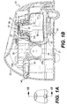
- Figure 1A is an elevational view of an atomizing device for use in an embodiment of the invention.
- Figure 1B is cross-sectional view along the line 1B-1B in Figure 1A .
- Figures 2A , 2B , 2C , and 2D show other elevational views of the atomizing device depicted in Figure 1A .
- Figure 3A shows a plan view of the lower surface of an orifice plate heater according to the invention.
- Figure 3B is an elevational view of the orifice plate heater of Figure 3A .
- Figure 4 is a cross-sectional view of a wick heater according to the invention.
- Figure 5 is an elevational view of an embodiment of our invention using the wick heater of Figure 4 .
- Figure 6A is a cross-sectional view of an embodiment using a heating chamber according to our invention.
- Figure 6B is an elevational view of the embodiment shown in Figure 6A .
- Figure 7 is a cross-sectional view of an embodiment of our invention employing a circuit board heater.
- a piezoelectrically-actuated atomization device 20 generally comprises an atomizing assembly 34, which includes an orifice plate 37 and a replaceable reservoir assembly 30.
- the reservoir assembly 30 includes a reservoir 31 containing fluid and a wick 56. When one reservoir assembly 30 is removed by a user and replaced with another reservoir assembly, the wick 56 automatically delivers fluid to the orifice plate 37.
- the atomization device 20 comprises a housing 22 formed as a hollow plastic shell with a removable base 21.
- a horizontal platform 25 extends across the interior of the housing 22.
- a battery 26 is supported by means of support prongs 25a that extend down from the underside of the platform 25 inside the housing 22.
- a printed circuit board 28 is supported on support elements 25b that extend upwardly from the platform 25.
- the liquid reservoir assembly 30 is replaceably mounted to the underside of a dome-like formation 25c on the platform 25.
- the liquid reservoir assembly 30 comprises the liquid container 31 for holding a liquid to be atomized, a plug 33, which closes the top of the container, and the wick 56, which extends from within the liquid container 31 through the plug 33, to a location above the liquid container 31.
- the plug 33 is constructed to allow removal and replacement of the complete liquid reservoir assembly 30 from the underside of the dome-like formation 25c on the platform 25.
- the wick 56 extends up through a center opening in the dome-like formation 25c.
- the wick 56 operates by capillary action to deliver liquid from within the liquid container 31 to a location just above the dome-like formation 25c on the platform 25.
- the atomizing assembly 34 comprises an annularly-shaped piezoelectric actuator element 35 and the circular orifice plate 37, which extends across and is soldered or otherwise affixed to the actuator element 35.
- a construction of a vibrator-type atomizing assembly is well known and is described, for example, in U.S. Patent No. 6,296,196 B1 to Denen et al . Accordingly, the atomizing assembly 34 will not be described in detail except to say that when alternating voltages are applied to opposite upper and lower sides of the actuator element 35, these voltages produce electrical fields across the actuator element and cause it to expand and contract in radial directions. This expansion and contraction is communicated to the orifice plate 37, causing it to flex, so that a center region thereof vibrates up and down.
- the center region of the orifice plate 37 is domed slightly in an upward direction, to provide stiffness and to enhance atomization.
- the center region is also formed with a plurality of minute orifices which extend through the orifice plate 37 from the lower or under surface of the orifice plate 37 to its upper surface. The vibration of the orifice plate 37 causes liquid droplets to be ejected through the minute orifices, out through opening 38, into the air.
- the battery 26 supplies electrical power to circuits on the printed circuit board 28, and these circuits convert the electrical power to high frequency alternating voltages.
- power may also be provided by a power cord plugged into an electrical outlet, or by other conventional means, in other embodiments.
- a suitable circuit for producing these voltages is shown and described by Denen et al.
- the alternating voltages are delivered to the opposite upper and lower sides of the actuator element 35 from the printed circuit board 28 via wires 29.
- the atomizing device may be operated during successive on and off times, the relative durations of which can be adjusted by a control switch 40 that is coupled to the printed circuit board 28 by conventional means.
- the on and off times may be controlled by a preset program, or controlled by a user interface working through a processor.
- the atomizing device is set to release atomized liquid approximately every 9 to 36 seconds, each time for about 11 milliseconds. Therefore, a puff of atomized liquid (for example, a fragrance) is emitted every 9 to 36 seconds, with the frequency of the puffs controlling the intensity of the fragrance.
- the atomizing assembly 34 is supported above the liquid reservoir assembly 30 such that the upper end of the wick 56 touches the underside of the orifice plate 37.
- the wick 56 delivers liquid from within the liquid reservoir 31 by capillary action to the underside of the orifice plate 37, which, upon vibration, causes the liquid to pass through its orifices and be ejected from its opposite side (that is, its upper surface) in the form of very small droplets.
- the horizontal platform 25 serves as a common structural support for both the liquid reservoir assembly 30 and the atomizing assembly 34.
- the horizontal platform 25 maintains the liquid reservoir assembly 30, and particularly, the upper end of the wick 56, in alignment with the orifice plate 37 of the atomizing assembly 34.
- the atomizing assembly 34 and the orifice plate 37 are resiliently mounted, the upper end of the wick 56 will press against the under surface of the orifice plate 37 and/or the actuator element 35 regardless of dimensional variations in the liquid reservoir assembly 30 that may occur due to manufacturing tolerances.
- wick 56 of the replacement liquid reservoir assembly 30 is higher or lower than the wick 56 of the original liquid reservoir assembly 30, the action of a spring 43 will allow the orifice plate 37 to move up and down according to the location of the wick 56 in the replacement reservoir assembly 30 so that the wick 56 will suitably press against the underside of the orifice plate 37 and/or the actuator element 35.
- the wick 56 is preferably formed of a substantially solid, dimensionally stable material so that it will not become overly deformed when pressed against the underside of the resiliently supported orifice plate 37.
- atomization devices may be substituted, as desired, in consideration of design choices, manufacturing costs, and the like.
- the above-described atomization device is preferred for use in systems according to our invention.
- fan assembly 60 is disposed beneath the reservoir assembly 30.
- the fan assembly 60 comprises a DC brushless fan 61.
- current can be delivered by wires (not shown) from the battery 26 directly to the DC brushless fan 61, or by wires 62 connecting the printed circuit board 28 to the DC brushless fan 61.
- the DC brushless fan 61 is activated to increase the airflow within the atomization device 20.
- the increased airflow enhances the evaporation and dispersion of atomized liquid droplets dispensed through the orifice plate 37 such that the amount of atomized liquid droplets that re-settle before evaporating is reduced.
- Figure 2A the device of Figure 1B is drawn without the housing 22 or the liquid reservoir assembly 30 so as to show another view of the DC brushless fan 61.
- Figure 2B shows the liquid reservoir assembly 30 mounted in place above the DC brushless fan 61.
- Figure 2C depicts the device of Figure 1B , as viewed at an angle from below with the base 21 not being shown.
- Figure 2D depicts the device of Figure 1B from the same angle as in Figure 2C .
- the base 21 is shown, and the DC brushless fan 61 is visible through an opening 21a formed in the base 21.
- the DC brushless fan 61 is used.
- other types of rotary fans are possible for use, depending on design considerations.
- the placement of the fan is not limited to that shown in Figure 1B . Rather, as long as the placement does not hinder liquid atomization and dispensing, any placement that allows the fan to promote airflow in or above the atomization device 20 and thereby enhance evaporation and dispersion of atomized liquid droplets dispensed through the orifice plate 37 is suitable.
- Piezoelectric fans may also be used instead of rotary fans.
- the fan assembly 60 disposed beneath the reservoir assembly 30 of Figure 1B would include a piezoelectric fan or fans.
- Fans for the atomizing device of our invention are not limited to rotary fans and piezoelectric fans. Any fan that can increase the airflow within or above the atomization device 20, and enhances the evaporation and dispersion of atomized liquid droplets dispensed through the orifice plate 37 such that the amount of atomized liquid droplets that re-settle before evaporating is reduced, is suitable.
- the fan assembly 60 may be activated at predetermined times defined with respect to the predetermined intervals, and may remain on for a predetermined period following each activation.
- the fan 61 can be activated at the beginning of each set amount of time that the device dispenses the liquid droplets, that is, the fan is synchronized to activate when the atomizing device releases a puff of atomized liquid. After each activation, the fan then remains on for three seconds (for instance) before shutting off.
- the fan can be activated after each time that the device has dispensed the liquid droplets for the set amount of time, that is, the fan is synchronized to activate after the atomizing device has released a puff of atomized liquid.
- the fan can be set to activate one second following the release of a puff of liquid (one second into the predetermined interval that separates the release of two puffs of atomized liquid). Thereafter, the fan remains on for 2 seconds (for instance) before shutting off.
- the fan may remain on as necessary.
- Figure 3A shows an orifice plate heater assembly 2.
- An orifice plate 37 has an area 37a which is formed with a plurality of minute apertures through which droplets of atomized liquid are dispensed. Drainage holes 37b may be formed in the orifice plate 37 to allow liquid to flow back to the wick. These drainage holes are described in detail in U.S. Patent No. 6,341,732 B1 to Martin et al .
- the orifice plate 37 is soldered or otherwise connected to a piezoelectric element 35, which has an electrode on both the upper and lower surface thereof.
- Two electric leads 35a are respectively attached to the electrodes on the upper and lower surface of the piezoelectric element 35.
- the electric lead 35a attached to the upper surface of the piezoelectric element 35 is not shown in Fig. 3A .
- the electric leads 35a convey alternating current (from the printed circuit board 28 as in Figure 1B ) to the piezoelectric element 35, causing it to expand and contract as previously described, creating vibrations that are communicated to the orifice plate 37.
- An insulator 35b concentrically surrounds the piezoelectric element 35 and separates it from a resistor trace 36b, to which two electrical leads 36a are attached.
- a surface mount resistor 36 is disposed on the lower surface of the orifice plate heater assembly 2 in contact with the resistor trace 36b such that when current flows (from the printed circuit board 28 as in Figure 1B ) through the electrical leads 36a through the resistor trace 36b to the surface mount resistor 36, the resistor trace 36b heats up.
- the heat generated by the surface mount resistor 36, and transferred to the resistor trace 36b heats the liquid passing through the area 37a of the orifice plate 37, resulting in an increase in the evaporation rate of the liquid droplets.
- the heater for the orifice plate is not limited to the orifice plate heater assembly 2.
- Other orifice plate heater assemblies capable of heating liquid passing through the orifice plate 37 are possible.
- FIG 4 illustrates an example of a wick heater according to the invention.
- Thermally conducting tube 5 preferably composed of a non-metal material such as plastic, is disposed to surround an upper portion of the wick 56.
- An air gap 9 is formed between the wick 56 and the thermally conducting tube 5.
- Extensions of the tube 5 form crimp tabs 5a that secure piezoelectric pump 8 in three places along the periphery thereof (see Figure 5 for a three-dimensional view of the crimp tabs 5a and the piezoelectric pump 8).
- An electrically insulating sleeve 6 surrounds the tube 5 and prevents the tube 5 from conducting heat away from the airgap 9.
- Heating wire 7, leading from printed circuit board 28 (as in Figure 1B ), is wound around the sleeve 6, as also shown in Figure 5 .
- heat is transferred from the heating wire 7 through the sleeve 6, the tube 5, and the air gap 9 to the wick 56.
- the temperature of the liquid in the wick 56 (through which liquid is being delivered to the orifice plate 37) is raised. This results in an increase in the temperature of the liquid being atomized, which in turn increases the evaporation rate of the liquid dispensed as liquid droplets.
- the wick heater is not limited to that shown in Figure 4 .
- the heating element need not be a wire such as heating wire 7 of this embodiment.
- Other means of heating the wick are possible, as would be known to one of ordinary skill in the art. Such means need only be capable of elevating the temperature of liquid in the wick 56 so that when the liquid is dispensed, the heated liquid evaporates more quickly.
- a device heats the liquid droplets after the droplets have been ejected from the atomization device.
- a heater assembly 70 has an inlet 72 through which liquid droplets dispensed from the orifice plate 37 enter the assembly 70, an outlet 73 through which the liquid droplets pass out of the assembly 70 into the ambient air, and a potted resistor element 71 preferably comprising a resistor 71a potted in a ceramic housing 71b with ceramic cement.
- Wires 74 from the printed circuit board 28 connect to the resistor 71a to cause the resistor 71a to heat when a current is passed through it, which in turn causes the entire heater assembly 70 to heat up.
- the heater assembly 70 elevates the temperature of the air inside a chamber defined by the heater assembly 70, beginning with inlet 72 and ending with outlet 73. This creates airflow in the chamber that transfers heat to liquid droplets passing through the chamber so that the temperature of the liquid droplets is elevated, enhancing evaporation. Also, preferably, convection currents caused by the heating chamber help liquid droplet dispersion by moving particles to a greater height, increasing the amount of time that the liquid droplets have to evaporate before settling occurs. Of course, other configurations for providing a heated chamber are possible, as would be understood by one of ordinary skill in the art.
- FIG. 7 shows a heating element 81 provided on the printed circuit board 28.
- Heating element 81 When the heating element 81 is heated, the temperature of the air inside the atomization device 20 is raised. This heating of the air preferably causes airflow through the opening 38 of the atomization device 20 through simple convection, enhancing the evaporation and dispersion of dispensed liquid droplets.
- Heating element 81 is preferably a resistance type heater.
- liquid atomizing devices having either a fan or a heater
- This invention provides liquid atomizing devices that are able to reduce the amount of atomized liquid droplets that settle onto adjacent surfaces before they can evaporate.
- the devices can preferably be used to dispense fragrances or insecticides, or to deliver medical, cosmetic, or humidifying sprays.
Landscapes
- Special Spraying Apparatus (AREA)
- Disinfection, Sterilisation Or Deodorisation Of Air (AREA)
- Nozzles (AREA)
- Investigating Or Analysing Biological Materials (AREA)
Claims (10)
- Flüssigkeitszerstäuber (20) zum Freisetzen von Flüssigkeitströpfchen aus einem Behälter (30), der eine Flüssigkeit enthält und einen porösen Docht (56) aufweist, mit dem Flüssigkeit aus dem Behälter (30) leitbar ist, welcher Zerstäuber aufweist:ein Gehäuse (22) undeine Zerstäubergruppe (34), die auf der waagerechten Plattform (25) angeordnet ist und ein Lochplättchen (37) mit Öffnungen aufweist, die von einem piezoelektrischen Element (35) in Schwingungen versetzbar ist, um aus dem Behälter (30) geleitete Flüssigkeit zu zerstäuben und als Tröpfchen durch die Öffnungen und durch den Durchlass an die Umluft auszugeben,dadurch gekennzeichnet, dassdas Gehäuse als hohle Kunststoffschale mit einem abnehmbaren Fuß (21) und einer waagerechten Plattform sowie einen Durchlass (38) in einer oberen Wand der Schale ausgebildet ist und dass ein Gebläse (61) im Gehäuse im Wesentlichen außerhalb eines Hauptteils angeordnet ist, den der Behälter und das Lochplättchen (37) umschließen;wobei das Gebläse unter dem Hauptteil angeordnet ist, um die Luftströmung um das Lochplättchen (37) herum zu verstärken und mindestens die Verdunstungsrate und / oder die Dispersion der durch die Öffnungen des Lochplättchens ausgegebenen Flüssigkeitströpfchen zu erhöhen.
- Zerstäuber (20) nach Anspruch 1, der die Flüssigkeitströpfchen in vorbestimmten Intervallen für eine voreingestellte Dauer abgibt und dessen Gebläse (61) in voreingestellten Intervallen mit deren Beginn koordiniert aktiviert wird und nach jedem Aktivieren für eine vorbestimmte Zeitspanne eingeschaltet bleibt.
- Zerstäuber nach Anspruch 1, bei dem das Gebläse (61) zu Beginn jedes voreingestellten Intervalls aktiviert wird, während dessen der Zerstäuber (20) die Flüssigkeitströpfchen ausgibt.
- Zerstäuber nach Anspruch 2, bei dem das Gebläse (61) nach dem Beginn jedes voreingestellten Intervalls aktiviert wird, während dessen der Zerstäuber (20) die Flüssigkeitströpfchen ausgegeben hat.
- Zerstäuber nach einem der vorgehenden Ansprüchen weiterhin mit:einem Heizelement (36), das mit dem Lochplättchen (37) verbunden ist;wobei das Heizelement (36) die aus dem Behälter (30) geleitete Flüssigkeit erwärmt, um die Verdunstungsrate der Flüssigkeitströpfchen zu erhöhen.
- Zerstäuber nach Anspruch 5, bei dem das Heizelement ein Auflötwiderstand (36) ist und der weiterhin aufweist:einen Isolator (35b), der das piezoelektrische Element (35) umgibt;eine Widerstandsleiterbahn (36b), die der Isolator (35b) vom piezoelektrischen Element (35) isoliert, wobei die Widerstandsleiterbahn (36b) in Berührung mit dem Auflötwiderstand (36) steht; undan die Widerstandsleiterbahn (35a) angeschlossene elektrische Zuleitungen (35a);wobei elektrischer Strom über die elektrischen Zuleitungen (35a) durch die Widerstandsleiterbahn (36b) zum Auflötwiderstand (36) fließt.
- Zerstäuber nach einem der Ansprüche 1 bis 4 weiterhin mit:einem Heizelement (7), das bei eingesetztem Behälter (30) auf einer Seite des Lochplättchens (37) den Docht (56) berührend angeordnet ist, damit Flüssigkeit dem Lochplättchen (37) zugeleitet werden kann, wobei das Heizelement (7) einen Oberteil des Dochts (56) erwärmt;wobei die Wärme aus dem Heizelement (7) die Temperatur der an das Lochplättchen ausgegebenen Flüssigkeit im Docht (56) erhöht, so dass die Verdunstungsrate der als Tröpfchen freigesetzten Flüssigkeit steigt.
- Zerstäuber nach Anspruch 7, bei dem das Heizelement (7) ein um den Oberteil des Dochts (56) gewickelter Draht ist und der weiterhin aufweist:ein Wärme leitendes Rohr (5), das den Oberteil des Dochts (56) umgibt derart, dass ein Luftspalt (9) zwischen dem Docht (56) und dem Wärme leitenden Rohr (5) entsteht, wobei das Wärme leitende Rohr (5) Ansätze aufweist, die Krimplaschen (5a) bilden, mit denen das piezoelektrische Element (8) an mehreren Stellen entlang seines Außenrands festgelegt ist; undeine elektrisch isolierende Hülse (6), die das Wärme leitende Rohr (5) umgibt und auf die der Draht (7) gewickelt ist.
- Zerstäuber nach einem der Ansprüche 1 bis 4 weiterhin mit:einer Heizkammer (7) auf einer der mit dem Docht in Verbindung stehenden gegenüber liegenden Seite des Lochplättchens (37), welche Heizkammer (70) einen Einlass (72) und einen Auslass (73) aufweist und so angeordnet ist, dass die durch die Öffnungen des Lochplättchens (37) in die Umluft frei gesetzten Flüssigkeitströpfchen durch die Heizkammer (70) aufwärts in den Einlass (72) ein- und aus dem Auslass (73) ausgeworfen werden.
- Zerstäuber (20) nach einem der Ansprüche 1 bis 4 weiterhin mit:einem Heizelement (81) auf einer Schaltungsplatine (28) im Gerät; wobeidas Heizelement (81) Wärme erzeugt, die die Verdunstungsrate der Flüssigkeitströpfchen steigert.
Applications Claiming Priority (2)
| Application Number | Priority Date | Filing Date | Title |
|---|---|---|---|
| US10/868,777 US7775459B2 (en) | 2004-06-17 | 2004-06-17 | Liquid atomizing device with reduced settling of atomized liquid droplets |
| PCT/US2005/021154 WO2006009743A1 (en) | 2004-06-17 | 2005-06-15 | Liquid atomizing device with reduced settling of atomized liquid droplets |
Publications (2)
| Publication Number | Publication Date |
|---|---|
| EP1773508A1 EP1773508A1 (de) | 2007-04-18 |
| EP1773508B1 true EP1773508B1 (de) | 2008-08-20 |
Family
ID=34972316
Family Applications (1)
| Application Number | Title | Priority Date | Filing Date |
|---|---|---|---|
| EP05759609A Expired - Lifetime EP1773508B1 (de) | 2004-06-17 | 2005-06-15 | Vorrichtung zur flüssigkeitszerstäubung mit verringerter absetzung von zerstäubten flüssigen tropfen |
Country Status (11)
| Country | Link |
|---|---|
| US (1) | US7775459B2 (de) |
| EP (1) | EP1773508B1 (de) |
| JP (1) | JP5032985B2 (de) |
| KR (1) | KR101377128B1 (de) |
| AT (1) | ATE405357T1 (de) |
| AU (1) | AU2005265005B2 (de) |
| CA (1) | CA2571108A1 (de) |
| DE (1) | DE602005009197D1 (de) |
| ES (1) | ES2311999T3 (de) |
| MX (1) | MXPA06014752A (de) |
| WO (1) | WO2006009743A1 (de) |
Cited By (1)
| Publication number | Priority date | Publication date | Assignee | Title |
|---|---|---|---|---|
| WO2024194475A1 (en) * | 2023-03-23 | 2024-09-26 | Zobele Holding Spa | Device and method for diffusing volatile substances |
Families Citing this family (172)
| Publication number | Priority date | Publication date | Assignee | Title |
|---|---|---|---|---|
| DE102005006374B3 (de) * | 2005-02-11 | 2006-07-20 | Pari GmbH Spezialisten für effektive Inhalation | Aerosolerzeugungsvorrichtung und Inhalationstherapiegerät mit einer derartigen Vorrichtung |
| GB0503098D0 (en) * | 2005-02-15 | 2005-03-23 | Reckitt Benckiser Uk Ltd | Spray device |
| ATE431306T1 (de) * | 2005-02-15 | 2009-05-15 | Reckitt Benckiser Uk Ltd | Abdichtungsanordnung für einen unter druck stehenden behälter |
| GB0503095D0 (en) * | 2005-02-15 | 2005-03-23 | Reckitt Benckiser Uk Ltd | Holder |
| US7490815B2 (en) * | 2005-11-14 | 2009-02-17 | The Procter & Gamble Company | Delivery system for dispensing volatile materials using an electromechanical transducer in combination with an air disturbance generator |
| US20070247555A1 (en) * | 2006-04-21 | 2007-10-25 | Diersing Steven L | Delivery system for dispensing volatile materials with high level of solids using an electromechanical transducer device |
| US7726320B2 (en) | 2006-10-18 | 2010-06-01 | R. J. Reynolds Tobacco Company | Tobacco-containing smoking article |
| GB0623052D0 (en) * | 2006-11-18 | 2006-12-27 | Reckitt Benckiser Uk Ltd | An assembly |
| GB0704379D0 (en) * | 2007-03-07 | 2007-04-11 | Reckitt Benckiser Uk Ltd | A Free standing treatment device for a dishwasher |
| WO2009006582A1 (en) * | 2007-07-03 | 2009-01-08 | Takasago International Corporation | Liquid-evaporate delivery device |
| US8296993B2 (en) * | 2007-11-16 | 2012-10-30 | Monster Mosquito Systems, Llc | Ultrasonic humidifier for repelling insects |
| FR2927240B1 (fr) * | 2008-02-13 | 2011-11-11 | Oreal | Tete de pulverisation comportant une sonotrode, parcourue par un canal d'amenee du produit |
| FR2927237B1 (fr) * | 2008-02-13 | 2011-12-23 | Oreal | Dispositif de pulverisation d'un produit cosmetique avec soufflage d'air chaud ou froid |
| FR2927238B1 (fr) * | 2008-02-13 | 2012-08-31 | Oreal | Dispositif de pulverisation comportant une sonotrode |
| EP2100670A1 (de) * | 2008-03-12 | 2009-09-16 | Microflow Engineering SA | Verfahren und Vorrichtung zur Verdampfung hochvisköser Flüssigkeiten mit minimalem Fallback |
| PL2641663T3 (pl) * | 2009-02-10 | 2015-05-29 | Henkel Ag&Co Kgaa | Urządzenie dozujące z automatyczną detekcją |
| NZ599789A (en) | 2009-10-09 | 2014-06-27 | Philip Morris Prod | Aerosol generator including multi-component wick |
| WO2011061480A1 (en) * | 2009-11-18 | 2011-05-26 | Reckitt Benckiser Llc | Surface treatment device and method |
| TWM399761U (en) * | 2010-04-07 | 2011-03-11 | Micro Base Technology Corp | Atomization device |
| US8757147B2 (en) | 2010-05-15 | 2014-06-24 | Minusa Holdings Llc | Personal vaporizing inhaler with internal light source |
| US11344683B2 (en) | 2010-05-15 | 2022-05-31 | Rai Strategic Holdings, Inc. | Vaporizer related systems, methods, and apparatus |
| US9078473B2 (en) | 2011-08-09 | 2015-07-14 | R.J. Reynolds Tobacco Company | Smoking articles and use thereof for yielding inhalation materials |
| US10066114B2 (en) | 2012-09-14 | 2018-09-04 | The Procter & Gamble Company | Ink jet delivery system comprising an improved perfume mixture |
| US10117460B2 (en) | 2012-10-08 | 2018-11-06 | Rai Strategic Holdings, Inc. | Electronic smoking article and associated method |
| US9578819B2 (en) * | 2013-01-24 | 2017-02-28 | Mark R Prescott | Pressurized growing air system for vertical and horizontal planting systems |
| US10031183B2 (en) | 2013-03-07 | 2018-07-24 | Rai Strategic Holdings, Inc. | Spent cartridge detection method and system for an electronic smoking article |
| US20140261486A1 (en) | 2013-03-12 | 2014-09-18 | R.J. Reynolds Tobacco Company | Electronic smoking article having a vapor-enhancing apparatus and associated method |
| US20140263695A1 (en) * | 2013-03-13 | 2014-09-18 | King Abdullah University Of Science And Technology | Method and apparatus for atomizing and vaporizing liquid |
| US9277770B2 (en) | 2013-03-14 | 2016-03-08 | R. J. Reynolds Tobacco Company | Atomizer for an aerosol delivery device formed from a continuously extending wire and related input, cartridge, and method |
| US20140261487A1 (en) | 2013-03-14 | 2014-09-18 | R. J. Reynolds Tobacco Company | Electronic smoking article with improved storage and transport of aerosol precursor compositions |
| US9918495B2 (en) | 2014-02-28 | 2018-03-20 | Rai Strategic Holdings, Inc. | Atomizer for an aerosol delivery device and related input, aerosol production assembly, cartridge, and method |
| US9491974B2 (en) | 2013-03-15 | 2016-11-15 | Rai Strategic Holdings, Inc. | Heating elements formed from a sheet of a material and inputs and methods for the production of atomizers |
| US9220302B2 (en) | 2013-03-15 | 2015-12-29 | R.J. Reynolds Tobacco Company | Cartridge for an aerosol delivery device and method for assembling a cartridge for a smoking article |
| US9609893B2 (en) | 2013-03-15 | 2017-04-04 | Rai Strategic Holdings, Inc. | Cartridge and control body of an aerosol delivery device including anti-rotation mechanism and related method |
| US9423152B2 (en) | 2013-03-15 | 2016-08-23 | R. J. Reynolds Tobacco Company | Heating control arrangement for an electronic smoking article and associated system and method |
| JP6074806B2 (ja) * | 2013-06-11 | 2017-02-08 | パナソニックIpマネジメント株式会社 | ミスト発生装置 |
| US11229239B2 (en) | 2013-07-19 | 2022-01-25 | Rai Strategic Holdings, Inc. | Electronic smoking article with haptic feedback |
| US10292424B2 (en) | 2013-10-31 | 2019-05-21 | Rai Strategic Holdings, Inc. | Aerosol delivery device including a pressure-based aerosol delivery mechanism |
| US9839237B2 (en) | 2013-11-22 | 2017-12-12 | Rai Strategic Holdings, Inc. | Reservoir housing for an electronic smoking article |
| ES2543928B1 (es) * | 2013-12-30 | 2016-05-31 | Zobele Espana Sa | Dispositivo para la difusión de sustancias volátiles |
| US9974334B2 (en) | 2014-01-17 | 2018-05-22 | Rai Strategic Holdings, Inc. | Electronic smoking article with improved storage of aerosol precursor compositions |
| US10575558B2 (en) | 2014-02-03 | 2020-03-03 | Rai Strategic Holdings, Inc. | Aerosol delivery device comprising multiple outer bodies and related assembly method |
| US9451791B2 (en) | 2014-02-05 | 2016-09-27 | Rai Strategic Holdings, Inc. | Aerosol delivery device with an illuminated outer surface and related method |
| US20150224268A1 (en) | 2014-02-07 | 2015-08-13 | R.J. Reynolds Tobacco Company | Charging Accessory Device for an Aerosol Delivery Device and Related System, Method, Apparatus, and Computer Program Product for Providing Interactive Services for Aerosol Delivery Devices |
| US9833019B2 (en) | 2014-02-13 | 2017-12-05 | Rai Strategic Holdings, Inc. | Method for assembling a cartridge for a smoking article |
| US9839238B2 (en) | 2014-02-28 | 2017-12-12 | Rai Strategic Holdings, Inc. | Control body for an electronic smoking article |
| US9597466B2 (en) | 2014-03-12 | 2017-03-21 | R. J. Reynolds Tobacco Company | Aerosol delivery system and related method, apparatus, and computer program product for providing control information to an aerosol delivery device via a cartridge |
| US11696604B2 (en) | 2014-03-13 | 2023-07-11 | Rai Strategic Holdings, Inc. | Aerosol delivery device and related method and computer program product for controlling an aerosol delivery device based on input characteristics |
| US9877510B2 (en) | 2014-04-04 | 2018-01-30 | Rai Strategic Holdings, Inc. | Sensor for an aerosol delivery device |
| US9924741B2 (en) | 2014-05-05 | 2018-03-27 | Rai Strategic Holdings, Inc. | Method of preparing an aerosol delivery device |
| US9955726B2 (en) | 2014-05-23 | 2018-05-01 | Rai Strategic Holdings, Inc. | Sealed cartridge for an aerosol delivery device and related assembly method |
| US9211980B1 (en) | 2014-06-20 | 2015-12-15 | The Procter & Gamble Company | Microfluidic delivery system for releasing fluid compositions |
| US9433696B2 (en) | 2014-06-20 | 2016-09-06 | The Procter & Gamble Company | Microfluidic delivery system for releasing fluid compositions |
| US9808812B2 (en) | 2014-06-20 | 2017-11-07 | The Procter & Gamble Company | Microfluidic delivery system |
| US10076585B2 (en) | 2014-06-20 | 2018-09-18 | The Procter & Gamble Company | Method of delivering a dose of a fluid composition from a microfluidic delivery cartridge |
| US10888119B2 (en) | 2014-07-10 | 2021-01-12 | Rai Strategic Holdings, Inc. | System and related methods, apparatuses, and computer program products for controlling operation of a device based on a read request |
| US10058123B2 (en) | 2014-07-11 | 2018-08-28 | R. J. Reynolds Tobacco Company | Heater for an aerosol delivery device and methods of formation thereof |
| US9609895B2 (en) | 2014-08-21 | 2017-04-04 | Rai Strategic Holdings, Inc. | System and related methods, apparatuses, and computer program products for testing components of an aerosol delivery device |
| US10765144B2 (en) | 2014-08-21 | 2020-09-08 | Rai Strategic Holdings, Inc. | Aerosol delivery device including a moveable cartridge and related assembly method |
| US9913493B2 (en) | 2014-08-21 | 2018-03-13 | Rai Strategic Holdings, Inc. | Aerosol delivery device including a moveable cartridge and related assembly method |
| US11051554B2 (en) | 2014-11-12 | 2021-07-06 | Rai Strategic Holdings, Inc. | MEMS-based sensor for an aerosol delivery device |
| CN104368021A (zh) * | 2014-11-28 | 2015-02-25 | 杭州盈天科学仪器有限公司 | 自动移动式喷雾灭菌器 |
| US10500600B2 (en) | 2014-12-09 | 2019-12-10 | Rai Strategic Holdings, Inc. | Gesture recognition user interface for an aerosol delivery device |
| US10321711B2 (en) | 2015-01-29 | 2019-06-18 | Rai Strategic Holdings, Inc. | Proximity detection for an aerosol delivery device |
| US10027016B2 (en) | 2015-03-04 | 2018-07-17 | Rai Strategic Holdings Inc. | Antenna for an aerosol delivery device |
| US9980516B2 (en) | 2015-03-09 | 2018-05-29 | Rai Strategic Holdings, Inc. | Aerosol delivery device including a wave guide and related method |
| US10172388B2 (en) | 2015-03-10 | 2019-01-08 | Rai Strategic Holdings, Inc. | Aerosol delivery device with microfluidic delivery component |
| WO2016154546A1 (en) | 2015-03-25 | 2016-09-29 | Clarke Consumer Products, Inc. | Fluid dispensing device |
| US9845962B2 (en) * | 2015-04-27 | 2017-12-19 | Crane USA Inc. | Portable air treatment system |
| US11000069B2 (en) | 2015-05-15 | 2021-05-11 | Rai Strategic Holdings, Inc. | Aerosol delivery device and methods of formation thereof |
| US10238145B2 (en) | 2015-05-19 | 2019-03-26 | Rai Strategic Holdings, Inc. | Assembly substation for assembling a cartridge for a smoking article |
| US11504489B2 (en) | 2015-07-17 | 2022-11-22 | Rai Strategic Holdings, Inc. | Contained liquid system for refilling aerosol delivery devices |
| US10966460B2 (en) | 2015-07-17 | 2021-04-06 | Rai Strategic Holdings, Inc. | Load-based detection of an aerosol delivery device in an assembled arrangement |
| US11033054B2 (en) | 2015-07-24 | 2021-06-15 | Rai Strategic Holdings, Inc. | Radio-frequency identification (RFID) authentication system for aerosol delivery devices |
| US10206429B2 (en) | 2015-07-24 | 2019-02-19 | Rai Strategic Holdings, Inc. | Aerosol delivery device with radiant heating |
| US10015987B2 (en) | 2015-07-24 | 2018-07-10 | Rai Strategic Holdings Inc. | Trigger-based wireless broadcasting for aerosol delivery devices |
| US11134544B2 (en) | 2015-07-24 | 2021-09-28 | Rai Strategic Holdings, Inc. | Aerosol delivery device with radiant heating |
| US10034494B2 (en) | 2015-09-15 | 2018-07-31 | Rai Strategic Holdings, Inc. | Reservoir for aerosol delivery devices |
| US10780192B2 (en) | 2015-09-16 | 2020-09-22 | The Procter & Gamble Company | Microfluidic delivery cartridges and methods of connecting cartridges with microfluidic delivery systems |
| US9636430B2 (en) * | 2015-09-16 | 2017-05-02 | The Procter & Gamble Company | Microfluidic delivery system and cartridge having an outer cover |
| US10500354B2 (en) | 2015-09-25 | 2019-12-10 | Sanmina Corporation | System and method for atomizing and monitoring a drug cartridge during inhalation treatments |
| US10058125B2 (en) | 2015-10-13 | 2018-08-28 | Rai Strategic Holdings, Inc. | Method for assembling an aerosol delivery device |
| US20170112194A1 (en) | 2015-10-21 | 2017-04-27 | Rai Strategic Holdings, Inc. | Rechargeable lithium-ion capacitor for an aerosol delivery device |
| US10918134B2 (en) | 2015-10-21 | 2021-02-16 | Rai Strategic Holdings, Inc. | Power supply for an aerosol delivery device |
| US10582726B2 (en) | 2015-10-21 | 2020-03-10 | Rai Strategic Holdings, Inc. | Induction charging for an aerosol delivery device |
| CN105268590B (zh) * | 2015-10-23 | 2017-07-18 | 上海应用技术学院 | 便携式智能超声波雾化器 |
| US12042809B2 (en) * | 2015-11-02 | 2024-07-23 | Altria Client Services Llc | Aerosol-generating system comprising a vibratable element |
| US10201187B2 (en) | 2015-11-02 | 2019-02-12 | Rai Strategic Holdings, Inc. | User interface for an aerosol delivery device |
| US10820630B2 (en) | 2015-11-06 | 2020-11-03 | Rai Strategic Holdings, Inc. | Aerosol delivery device including a wirelessly-heated atomizer and related method |
| US10440992B2 (en) | 2015-12-07 | 2019-10-15 | Rai Strategic Holdings, Inc. | Motion sensing for an aerosol delivery device |
| US9955733B2 (en) | 2015-12-07 | 2018-05-01 | Rai Strategic Holdings, Inc. | Camera for an aerosol delivery device |
| US11291252B2 (en) | 2015-12-18 | 2022-04-05 | Rai Strategic Holdings, Inc. | Proximity sensing for an aerosol delivery device |
| US10092036B2 (en) | 2015-12-28 | 2018-10-09 | Rai Strategic Holdings, Inc. | Aerosol delivery device including a housing and a coupler |
| US10051891B2 (en) | 2016-01-05 | 2018-08-21 | Rai Strategic Holdings, Inc. | Capacitive sensing input device for an aerosol delivery device |
| US10194694B2 (en) | 2016-01-05 | 2019-02-05 | Rai Strategic Holdings, Inc. | Aerosol delivery device with improved fluid transport |
| US10258086B2 (en) | 2016-01-12 | 2019-04-16 | Rai Strategic Holdings, Inc. | Hall effect current sensor for an aerosol delivery device |
| US10104912B2 (en) | 2016-01-20 | 2018-10-23 | Rai Strategic Holdings, Inc. | Control for an induction-based aerosol delivery device |
| US10015989B2 (en) | 2016-01-27 | 2018-07-10 | Rai Strategic Holdings, Inc. | One-way valve for refilling an aerosol delivery device |
| US11412781B2 (en) | 2016-02-12 | 2022-08-16 | Rai Strategic Holdings, Inc. | Adapters for refilling an aerosol delivery device |
| US9936733B2 (en) | 2016-03-09 | 2018-04-10 | Rai Strategic Holdings, Inc. | Accessory configured to charge an aerosol delivery device and related method |
| US11207478B2 (en) | 2016-03-25 | 2021-12-28 | Rai Strategic Holdings, Inc. | Aerosol production assembly including surface with micro-pattern |
| US10334880B2 (en) | 2016-03-25 | 2019-07-02 | Rai Strategic Holdings, Inc. | Aerosol delivery device including connector comprising extension and receptacle |
| US10945462B2 (en) | 2016-04-12 | 2021-03-16 | Rai Strategic Holdings, Inc. | Detachable power source for an aerosol delivery device |
| US10333339B2 (en) | 2016-04-12 | 2019-06-25 | Rai Strategic Holdings, Inc. | Charger for an aerosol delivery device |
| US10028534B2 (en) | 2016-04-20 | 2018-07-24 | Rai Strategic Holdings, Inc. | Aerosol delivery device, and associated apparatus and method of formation thereof |
| US10405579B2 (en) | 2016-04-29 | 2019-09-10 | Rai Strategic Holdings, Inc. | Methods for assembling a cartridge for an aerosol delivery device, and associated systems and apparatuses |
| US10959458B2 (en) | 2016-06-20 | 2021-03-30 | Rai Strategic Holdings, Inc. | Aerosol delivery device including an electrical generator assembly |
| US10085485B2 (en) | 2016-07-06 | 2018-10-02 | Rai Strategic Holdings, Inc. | Aerosol delivery device with a reservoir housing and a vaporizer assembly |
| US10405581B2 (en) | 2016-07-08 | 2019-09-10 | Rai Strategic Holdings, Inc. | Gas sensing for an aerosol delivery device |
| US10231485B2 (en) | 2016-07-08 | 2019-03-19 | Rai Strategic Holdings, Inc. | Radio frequency to direct current converter for an aerosol delivery device |
| US10463078B2 (en) | 2016-07-08 | 2019-11-05 | Rai Strategic Holdings, Inc. | Aerosol delivery device with condensing and non-condensing vaporization |
| US10617151B2 (en) | 2016-07-21 | 2020-04-14 | Rai Strategic Holdings, Inc. | Aerosol delivery device with a liquid transport element comprising a porous monolith and related method |
| US10602775B2 (en) | 2016-07-21 | 2020-03-31 | Rai Strategic Holdings, Inc. | Aerosol delivery device with a unitary reservoir and liquid transport element comprising a porous monolith and related method |
| US11019847B2 (en) | 2016-07-28 | 2021-06-01 | Rai Strategic Holdings, Inc. | Aerosol delivery devices including a selector and related methods |
| US10765146B2 (en) | 2016-08-08 | 2020-09-08 | Rai Strategic Holdings, Inc. | Boost converter for an aerosol delivery device |
| US20180055090A1 (en) * | 2016-08-31 | 2018-03-01 | Altria Client Services Llc | Methods and systems for cartridge identification |
| US12472316B2 (en) | 2016-09-09 | 2025-11-18 | Rai Strategic Holdings, Inc. | Analog control component for an aerosol delivery device |
| US11937647B2 (en) | 2016-09-09 | 2024-03-26 | Rai Strategic Holdings, Inc. | Fluidic control for an aerosol delivery device |
| US10080387B2 (en) | 2016-09-23 | 2018-09-25 | Rai Strategic Holdings, Inc. | Aerosol delivery device with replaceable wick and heater assembly |
| USD831813S1 (en) | 2016-10-07 | 2018-10-23 | S. C. Johnson & Sons, Inc. | Volatile material dispenser |
| USD834168S1 (en) | 2016-10-07 | 2018-11-20 | S. C. Johnson & Son, Inc. | Dispenser |
| USD834167S1 (en) | 2016-10-07 | 2018-11-20 | S. C. Johnson & Son, Inc. | Dispenser |
| US10477896B2 (en) | 2016-10-12 | 2019-11-19 | Rai Strategic Holdings, Inc. | Photodetector for measuring aerosol precursor composition in an aerosol delivery device |
| US10524508B2 (en) | 2016-11-15 | 2020-01-07 | Rai Strategic Holdings, Inc. | Induction-based aerosol delivery device |
| US10492530B2 (en) | 2016-11-15 | 2019-12-03 | Rai Strategic Holdings, Inc. | Two-wire authentication system for an aerosol delivery device |
| US9864947B1 (en) | 2016-11-15 | 2018-01-09 | Rai Strategic Holdings, Inc. | Near field communication for a tobacco-based article or package therefor |
| US11103012B2 (en) | 2016-11-17 | 2021-08-31 | Rai Strategic Holdings, Inc. | Satellite navigation for an aerosol delivery device |
| US10206431B2 (en) | 2016-11-18 | 2019-02-19 | Rai Strategic Holdings, Inc. | Charger for an aerosol delivery device |
| US10172392B2 (en) | 2016-11-18 | 2019-01-08 | Rai Strategic Holdings, Inc. | Humidity sensing for an aerosol delivery device |
| US10653183B2 (en) | 2016-11-18 | 2020-05-19 | Rai Strategic Holdings, Inc. | Power source for an aerosol delivery device |
| US10524509B2 (en) | 2016-11-18 | 2020-01-07 | Rai Strategic Holdings, Inc. | Pressure sensing for an aerosol delivery device |
| US11160895B2 (en) * | 2016-11-21 | 2021-11-02 | Inventure Labs Llc | Automated modular environment modification device |
| US10537137B2 (en) | 2016-11-22 | 2020-01-21 | Rai Strategic Holdings, Inc. | Rechargeable lithium-ion battery for an aerosol delivery device |
| US10149917B2 (en) | 2016-11-22 | 2018-12-11 | The Procter & Gamble Company | Fluid composition and a microfluidic delivery cartridge comprising the same |
| US11013266B2 (en) | 2016-12-09 | 2021-05-25 | Rai Strategic Holdings, Inc. | Aerosol delivery device sensory system including an infrared sensor and related method |
| US10517326B2 (en) | 2017-01-27 | 2019-12-31 | Rai Strategic Holdings, Inc. | Secondary battery for an aerosol delivery device |
| US10827783B2 (en) | 2017-02-27 | 2020-11-10 | Rai Strategic Holdings, Inc. | Digital compass for an aerosol delivery device |
| US12103020B2 (en) | 2017-04-10 | 2024-10-01 | The Procter & Gamble Company | Microfluidic delivery device and method for dispensing a fluid composition upward into the air |
| US11691162B2 (en) | 2017-04-10 | 2023-07-04 | The Procter & Gamble Company | Microfluidic delivery cartridge for use with a microfluidic delivery device |
| US11305301B2 (en) | 2017-04-10 | 2022-04-19 | The Procter & Gamble Company | Microfluidic delivery device for dispensing and redirecting a fluid composition in the air |
| US10314340B2 (en) | 2017-04-21 | 2019-06-11 | Rai Strategic Holdings, Inc. | Refillable aerosol delivery device and related method |
| US11297876B2 (en) | 2017-05-17 | 2022-04-12 | Rai Strategic Holdings, Inc. | Aerosol delivery device |
| US11589621B2 (en) | 2017-05-23 | 2023-02-28 | Rai Strategic Holdings, Inc. | Heart rate monitor for an aerosol delivery device |
| US10517330B2 (en) | 2017-05-23 | 2019-12-31 | RAI Stategic Holdings, Inc. | Heart rate monitor for an aerosol delivery device |
| US10842197B2 (en) | 2017-07-12 | 2020-11-24 | Rai Strategic Holdings, Inc. | Detachable container for aerosol delivery having pierceable membrane |
| US10349674B2 (en) | 2017-07-17 | 2019-07-16 | Rai Strategic Holdings, Inc. | No-heat, no-burn smoking article |
| US11337456B2 (en) | 2017-07-17 | 2022-05-24 | Rai Strategic Holdings, Inc. | Video analytics camera system for an aerosol delivery device |
| US10505383B2 (en) | 2017-09-19 | 2019-12-10 | Rai Strategic Holdings, Inc. | Intelligent charger for an aerosol delivery device |
| US11039645B2 (en) | 2017-09-19 | 2021-06-22 | Rai Strategic Holdings, Inc. | Differential pressure sensor for an aerosol delivery device |
| US10660370B2 (en) | 2017-10-12 | 2020-05-26 | Rai Strategic Holdings, Inc. | Aerosol delivery device including a control body, an atomizer body, and a cartridge and related methods |
| US10517332B2 (en) | 2017-10-31 | 2019-12-31 | Rai Strategic Holdings, Inc. | Induction heated aerosol delivery device |
| US10806181B2 (en) | 2017-12-08 | 2020-10-20 | Rai Strategic Holdings, Inc. | Quasi-resonant flyback converter for an induction-based aerosol delivery device |
| US11517642B2 (en) | 2017-12-21 | 2022-12-06 | S. C. Johnson & Son, Inc. | Piezoelectric active emitting device with improved air flow output |
| US10555558B2 (en) | 2017-12-29 | 2020-02-11 | Rai Strategic Holdings, Inc. | Aerosol delivery device providing flavor control |
| US11019850B2 (en) | 2018-02-26 | 2021-06-01 | Rai Strategic Holdings, Inc. | Heat conducting substrate for electrically heated aerosol delivery device |
| CN108855747A (zh) * | 2018-04-20 | 2018-11-23 | 广州迪杰帕尔电子科技有限公司 | 一种持续供水水雾机 |
| US10806816B2 (en) | 2018-05-15 | 2020-10-20 | The Procter & Gamble Company | Microfluidic cartridge and microfluidic delivery device comprising the same |
| US10328173B2 (en) | 2018-10-08 | 2019-06-25 | Apptec, Inc. | Long-acting deodorization of noxious odors using a water-based deodorizing solution in an ultrasonic dispenser |
| CN109237689A (zh) * | 2018-10-11 | 2019-01-18 | 珠海格力电器股份有限公司 | 挡水结构及包括其的加湿器 |
| CN109405110B (zh) * | 2018-10-11 | 2020-09-29 | 珠海格力电器股份有限公司 | 空气处理装置及控制方法 |
| US12478112B2 (en) | 2018-10-30 | 2025-11-25 | R.J. Reynolds Tobacco Company | Smoking article cartridge |
| JP2020130270A (ja) * | 2019-02-14 | 2020-08-31 | Scentee株式会社 | カートリッジ装置、及びディフューザ装置 |
| JP6611220B1 (ja) * | 2019-03-28 | 2019-11-27 | 株式会社アロマジョイン | 香りディスプレイのブースタ装置 |
| US20210038910A1 (en) * | 2019-08-07 | 2021-02-11 | Francis KWOK | Skincare system providing an aroma liquid atomizer unit and a phototherapy unit |
| US11407000B2 (en) | 2019-09-23 | 2022-08-09 | S. C. Johnson & Son, Inc. | Volatile material dispenser |
| FR3101779A1 (fr) * | 2019-10-09 | 2021-04-16 | Armand Delsol | Dispositif de diffusion par effet piezoélectrique |
| CN111468320A (zh) * | 2020-05-20 | 2020-07-31 | 深圳市创百智能科技有限公司 | 一种超声波雾化喷射设备 |
| US12514294B2 (en) | 2020-07-01 | 2026-01-06 | Nicoventures Trading Limited | 3D-printed substrate for aerosol delivery device |
| US20220096687A1 (en) * | 2020-09-29 | 2022-03-31 | Tabitha Angel Bryant | Sanitizer Aerosol Dispensing Apparatus |
| US20240050616A1 (en) * | 2020-11-09 | 2024-02-15 | Ctr, Lda | Device and method for dispensing and/or diffusing volatile substances, especially for dispensing and/or diffusing fragrances and/or active substances |
| EP4266915B1 (de) * | 2020-12-23 | 2025-02-12 | Philip Morris Products S.A. | Aerosolerzeugungssystem mit einem wandler |
| US20260041081A1 (en) * | 2024-08-07 | 2026-02-12 | Hoda Ballout | Skeeter weeper® smart pest control misting system |
Family Cites Families (41)
| Publication number | Priority date | Publication date | Assignee | Title |
|---|---|---|---|---|
| US3901443A (en) | 1973-02-06 | 1975-08-26 | Tdk Electronics Co Ltd | Ultrasonic wave nebulizer |
| US3997115A (en) | 1976-03-10 | 1976-12-14 | Lawrence Peska Associates, Inc. | Portable atomizer for liquids |
| CA1206996A (en) | 1982-01-18 | 1986-07-02 | Naoyoshi Maehara | Ultrasonic liquid ejecting apparatus |
| DE3574344D1 (en) * | 1984-08-29 | 1989-12-28 | Omron Tateisi Electronics Co | Ultrasonic atomizer |
| EP0174033B1 (de) * | 1984-09-07 | 1991-03-27 | OMRON Corporation | Schwingungserzeuger für ein Inhalationsgerät mit Ultraschallzerstäubung |
| US4746466A (en) | 1986-03-03 | 1988-05-24 | Tdk Corporation | Ultrasonic atomizing apparatus |
| EP0401060B1 (de) | 1989-05-31 | 1993-06-30 | Conceptair Anstalt | Verfahren und elektrische, elektronische und mechanische Vorrichtung zum Verteilen, Dosieren oder Diffundieren, von flüssigen oder gasförmigen Aromen, Arzneien und anderen flüssigen oder viskösen Produkten |
| JP2754798B2 (ja) * | 1989-11-09 | 1998-05-20 | 松下電器産業株式会社 | 超音波加湿ユニット |
| US4961885A (en) | 1989-11-24 | 1990-10-09 | Elecsys Ltd. | Ultrasonic nebulizer |
| JP2698488B2 (ja) * | 1991-06-21 | 1998-01-19 | 耕司 戸田 | 超音波噴霧装置 |
| DE69206824C5 (de) * | 1991-12-04 | 2009-07-09 | The Technology Partnership PLC, Melbourn, Royston | Vorrichtung und verfahren zur erzeugung von fluessigkeitstroepfchen |
| GB2272389B (en) | 1992-11-04 | 1996-07-24 | Bespak Plc | Dispensing apparatus |
| FR2721839B1 (fr) | 1994-07-04 | 1996-10-25 | Imra Europe Sa | Dispositif de pulverisation, notamment d'eau sous forme de micro-goutelettes, apte a fonctionner dans un milieu non stationnaire |
| JPH0852216A (ja) * | 1994-08-13 | 1996-02-27 | Koji Toda | 超音波吸入装置 |
| DE29504734U1 (de) * | 1995-03-20 | 1996-07-18 | Perycut-Chemie AG, Zürich | Verdampfervorrichtung |
| IT1277427B1 (it) | 1995-08-03 | 1997-11-10 | Miat Spa | Apparecchio aerosol ad ultrasuoni |
| US5620633A (en) | 1995-08-17 | 1997-04-15 | Circulair, Inc. | Spray misting device for use with a portable-sized fan |
| US5667732A (en) | 1995-08-30 | 1997-09-16 | Lederer; Jeffrey H. | Compact portable misting fan |
| FR2743313B1 (fr) * | 1996-01-04 | 1998-02-06 | Imra Europe Sa | Dispositif de pulverisation a rendement eleve notamment d'eau sous forme de micro-gouttelettes |
| US6247525B1 (en) | 1997-03-20 | 2001-06-19 | Georgia Tech Research Corporation | Vibration induced atomizers |
| US6161777A (en) | 1997-08-08 | 2000-12-19 | C. Michael Carter | Portable spraying and drinking apparatus |
| US6390453B1 (en) * | 1997-10-22 | 2002-05-21 | Microfab Technologies, Inc. | Method and apparatus for delivery of fragrances and vapors to the nose |
| ATE344108T1 (de) | 1998-12-01 | 2006-11-15 | Microflow Eng Sa | Inhalator mit ultraschallzerstäuber dessen sprühöffnungen den maximalamplituden eines stehenden wellenmusters überlagert sind |
| HK1043752B (zh) | 1999-03-05 | 2005-02-25 | 约翰逊父子公司 | 振动液体雾化器及其操作方法 |
| US6293474B1 (en) * | 1999-03-08 | 2001-09-25 | S. C. Johnson & Son, Inc. | Delivery system for dispensing volatiles |
| JP2000312849A (ja) * | 1999-04-27 | 2000-11-14 | Fukoku Co Ltd | 超音波霧化装置 |
| US6216961B1 (en) | 1999-05-12 | 2001-04-17 | Misty Mate Inc | Fan propelled mister |
| WO2001030404A1 (en) | 1999-10-29 | 2001-05-03 | E. One Co., Ltd. | Scent diffusion apparatus and method thereof |
| US6341732B1 (en) * | 2000-06-19 | 2002-01-29 | S. C. Johnson & Son, Inc. | Method and apparatus for maintaining control of liquid flow in a vibratory atomizing device |
| EP1182292A1 (de) * | 2000-08-16 | 2002-02-27 | The Procter & Gamble Company | Vorrichtung zum Reinigen und zum Auffrischen von Textilien mit Ultraschallvernebler und Ultraschallvernebler |
| DK1184083T3 (da) | 2000-08-30 | 2003-10-13 | Pfeiffer Erich Gmbh & Co Kg | Intelligent miniatureduftdispenserindretning til afgivelse af duft i forskellige anvendelsesområder og omgivelser |
| US6340283B1 (en) | 2000-08-31 | 2002-01-22 | Graves Spray Supply, Inc. | Adjustable impingement dual blower apparatus |
| US6390543B1 (en) * | 2000-08-31 | 2002-05-21 | Meritor Light Vehicle Technology, Llc | Saw tooth sunroof seal |
| US6378988B1 (en) | 2001-03-19 | 2002-04-30 | Microfab Technologies, Inc. | Cartridge element for micro jet dispensing |
| US6623785B2 (en) | 2001-06-07 | 2003-09-23 | Hewlett-Packard Development Company, L.P. | Pharmaceutical dispensing apparatus and method |
| JP2003117456A (ja) * | 2001-10-11 | 2003-04-22 | Tominaga Oil Pump Mfg Co Ltd | 霧発生装置 |
| US6793149B2 (en) * | 2002-02-04 | 2004-09-21 | S. C. Johnson & Son, Inc. | Method and apparatus for evaporating multi-component liquids |
| AU2002230267A1 (en) | 2002-02-11 | 2003-09-04 | Sara Lee/De N.V. | Liquid spray-head, apparatus comprising a liquid spray-head and container therefore |
| US6843430B2 (en) * | 2002-05-24 | 2005-01-18 | S. C. Johnson & Son, Inc. | Low leakage liquid atomization device |
| ES2300589T3 (es) * | 2002-06-06 | 2008-06-16 | S.C. JOHNSON & SON, INC. | Volatilizacion de superficie localizada. |
| US6896193B2 (en) * | 2002-11-26 | 2005-05-24 | S.C. Johnson & Son, Inc. | Atomizer with improved wire type atomizing element support and method of making same |
-
2004
- 2004-06-17 US US10/868,777 patent/US7775459B2/en active Active
-
2005
- 2005-06-15 AU AU2005265005A patent/AU2005265005B2/en not_active Ceased
- 2005-06-15 EP EP05759609A patent/EP1773508B1/de not_active Expired - Lifetime
- 2005-06-15 MX MXPA06014752A patent/MXPA06014752A/es active IP Right Grant
- 2005-06-15 KR KR1020067026601A patent/KR101377128B1/ko not_active Expired - Lifetime
- 2005-06-15 WO PCT/US2005/021154 patent/WO2006009743A1/en not_active Ceased
- 2005-06-15 AT AT05759609T patent/ATE405357T1/de not_active IP Right Cessation
- 2005-06-15 JP JP2007516685A patent/JP5032985B2/ja not_active Expired - Fee Related
- 2005-06-15 CA CA002571108A patent/CA2571108A1/en not_active Abandoned
- 2005-06-15 ES ES05759609T patent/ES2311999T3/es not_active Expired - Lifetime
- 2005-06-15 DE DE602005009197T patent/DE602005009197D1/de not_active Expired - Lifetime
Cited By (1)
| Publication number | Priority date | Publication date | Assignee | Title |
|---|---|---|---|---|
| WO2024194475A1 (en) * | 2023-03-23 | 2024-09-26 | Zobele Holding Spa | Device and method for diffusing volatile substances |
Also Published As
| Publication number | Publication date |
|---|---|
| AU2005265005B2 (en) | 2010-12-02 |
| DE602005009197D1 (de) | 2008-10-02 |
| US7775459B2 (en) | 2010-08-17 |
| WO2006009743A1 (en) | 2006-01-26 |
| ES2311999T3 (es) | 2009-02-16 |
| ATE405357T1 (de) | 2008-09-15 |
| JP5032985B2 (ja) | 2012-09-26 |
| MXPA06014752A (es) | 2007-03-12 |
| JP2008503334A (ja) | 2008-02-07 |
| US20050279854A1 (en) | 2005-12-22 |
| KR101377128B1 (ko) | 2014-04-01 |
| KR20070040338A (ko) | 2007-04-16 |
| EP1773508A1 (de) | 2007-04-18 |
| AU2005265005A1 (en) | 2006-01-26 |
| CA2571108A1 (en) | 2006-01-26 |
Similar Documents
| Publication | Publication Date | Title |
|---|---|---|
| EP1773508B1 (de) | Vorrichtung zur flüssigkeitszerstäubung mit verringerter absetzung von zerstäubten flüssigen tropfen | |
| KR102306074B1 (ko) | 미세유체 전달 장치와 함께 사용하기 위한 미세유체 전달 카트리지 | |
| EP2841208B1 (de) | Zerstäubersystem | |
| CA2953117C (en) | Microfluidic delivery system | |
| US8135265B2 (en) | Device for emitting volatile compositions while reducing surface deposition and improving scent noticeability | |
| US6378780B1 (en) | Delivery system for dispensing volatiles | |
| KR102369404B1 (ko) | 유체 조성물을 공기 중으로 상향으로 분배하기 위한 미세유체 전달 장치 및 방법 | |
| JP2019171088A (ja) | ある用量の流体組成物をマイクロ流体送達カートリッジから送達する方法 | |
| US20080099572A1 (en) | Delivery system for dispensing volatiles | |
| JP2018535711A (ja) | マイクロ流体送達システム、及び外側カバーを有するカートリッジ | |
| JP2018538072A (ja) | マイクロ流体送達カートリッジ、及びカートリッジをマイクロ流体送達システムと接続する方法 | |
| RU2000106031A (ru) | Распределительное устройство | |
| JP2018537263A (ja) | マイクロ流体送達システム、及び外側カバーを有するカートリッジ | |
| JP2017522916A (ja) | ネブライザを有する揮発性物質ディスペンサ及びネブライザ組立体 | |
| KR20090004897A (ko) | 휘발성 물질 분배기 | |
| EP1430958A2 (de) | Piezoelektrisches Sprühsystem zum Austragen flüchtiger Stoffe | |
| KR100577590B1 (ko) | 초음파 진동자를 이용한 액체 휘산기 | |
| GB2588492A (en) | A dispenser |
Legal Events
| Date | Code | Title | Description |
|---|---|---|---|
| PUAI | Public reference made under article 153(3) epc to a published international application that has entered the european phase |
Free format text: ORIGINAL CODE: 0009012 |
|
| 17P | Request for examination filed |
Effective date: 20070103 |
|
| AK | Designated contracting states |
Kind code of ref document: A1 Designated state(s): AT BE BG CH CY CZ DE DK EE ES FI FR GB GR HU IE IS IT LI LT LU MC NL PL PT RO SE SI SK TR |
|
| 17Q | First examination report despatched |
Effective date: 20070806 |
|
| DAX | Request for extension of the european patent (deleted) | ||
| GRAP | Despatch of communication of intention to grant a patent |
Free format text: ORIGINAL CODE: EPIDOSNIGR1 |
|
| GRAS | Grant fee paid |
Free format text: ORIGINAL CODE: EPIDOSNIGR3 |
|
| GRAA | (expected) grant |
Free format text: ORIGINAL CODE: 0009210 |
|
| AK | Designated contracting states |
Kind code of ref document: B1 Designated state(s): AT BE BG CH CY CZ DE DK EE ES FI FR GB GR HU IE IS IT LI LT LU MC NL PL PT RO SE SI SK TR |
|
| REG | Reference to a national code |
Ref country code: GB Ref legal event code: FG4D |
|
| REG | Reference to a national code |
Ref country code: CH Ref legal event code: EP |
|
| REG | Reference to a national code |
Ref country code: IE Ref legal event code: FG4D |
|
| REF | Corresponds to: |
Ref document number: 602005009197 Country of ref document: DE Date of ref document: 20081002 Kind code of ref document: P |
|
| PG25 | Lapsed in a contracting state [announced via postgrant information from national office to epo] |
Ref country code: IS Free format text: LAPSE BECAUSE OF FAILURE TO SUBMIT A TRANSLATION OF THE DESCRIPTION OR TO PAY THE FEE WITHIN THE PRESCRIBED TIME-LIMIT Effective date: 20081220 Ref country code: LT Free format text: LAPSE BECAUSE OF FAILURE TO SUBMIT A TRANSLATION OF THE DESCRIPTION OR TO PAY THE FEE WITHIN THE PRESCRIBED TIME-LIMIT Effective date: 20080820 Ref country code: NL Free format text: LAPSE BECAUSE OF FAILURE TO SUBMIT A TRANSLATION OF THE DESCRIPTION OR TO PAY THE FEE WITHIN THE PRESCRIBED TIME-LIMIT Effective date: 20080820 |
|
| REG | Reference to a national code |
Ref country code: ES Ref legal event code: FG2A Ref document number: 2311999 Country of ref document: ES Kind code of ref document: T3 |
|
| PG25 | Lapsed in a contracting state [announced via postgrant information from national office to epo] |
Ref country code: FI Free format text: LAPSE BECAUSE OF FAILURE TO SUBMIT A TRANSLATION OF THE DESCRIPTION OR TO PAY THE FEE WITHIN THE PRESCRIBED TIME-LIMIT Effective date: 20080820 Ref country code: SI Free format text: LAPSE BECAUSE OF FAILURE TO SUBMIT A TRANSLATION OF THE DESCRIPTION OR TO PAY THE FEE WITHIN THE PRESCRIBED TIME-LIMIT Effective date: 20080820 Ref country code: AT Free format text: LAPSE BECAUSE OF FAILURE TO SUBMIT A TRANSLATION OF THE DESCRIPTION OR TO PAY THE FEE WITHIN THE PRESCRIBED TIME-LIMIT Effective date: 20080820 |
|
| PG25 | Lapsed in a contracting state [announced via postgrant information from national office to epo] |
Ref country code: BE Free format text: LAPSE BECAUSE OF FAILURE TO SUBMIT A TRANSLATION OF THE DESCRIPTION OR TO PAY THE FEE WITHIN THE PRESCRIBED TIME-LIMIT Effective date: 20080820 |
|
| PG25 | Lapsed in a contracting state [announced via postgrant information from national office to epo] |
Ref country code: DK Free format text: LAPSE BECAUSE OF FAILURE TO SUBMIT A TRANSLATION OF THE DESCRIPTION OR TO PAY THE FEE WITHIN THE PRESCRIBED TIME-LIMIT Effective date: 20080820 Ref country code: BG Free format text: LAPSE BECAUSE OF FAILURE TO SUBMIT A TRANSLATION OF THE DESCRIPTION OR TO PAY THE FEE WITHIN THE PRESCRIBED TIME-LIMIT Effective date: 20081120 |
|
| PG25 | Lapsed in a contracting state [announced via postgrant information from national office to epo] |
Ref country code: SK Free format text: LAPSE BECAUSE OF FAILURE TO SUBMIT A TRANSLATION OF THE DESCRIPTION OR TO PAY THE FEE WITHIN THE PRESCRIBED TIME-LIMIT Effective date: 20080820 Ref country code: RO Free format text: LAPSE BECAUSE OF FAILURE TO SUBMIT A TRANSLATION OF THE DESCRIPTION OR TO PAY THE FEE WITHIN THE PRESCRIBED TIME-LIMIT Effective date: 20080820 Ref country code: PT Free format text: LAPSE BECAUSE OF FAILURE TO SUBMIT A TRANSLATION OF THE DESCRIPTION OR TO PAY THE FEE WITHIN THE PRESCRIBED TIME-LIMIT Effective date: 20090120 Ref country code: CZ Free format text: LAPSE BECAUSE OF FAILURE TO SUBMIT A TRANSLATION OF THE DESCRIPTION OR TO PAY THE FEE WITHIN THE PRESCRIBED TIME-LIMIT Effective date: 20080820 |
|
| PLBE | No opposition filed within time limit |
Free format text: ORIGINAL CODE: 0009261 |
|
| STAA | Information on the status of an ep patent application or granted ep patent |
Free format text: STATUS: NO OPPOSITION FILED WITHIN TIME LIMIT |
|
| 26N | No opposition filed |
Effective date: 20090525 |
|
| PG25 | Lapsed in a contracting state [announced via postgrant information from national office to epo] |
Ref country code: EE Free format text: LAPSE BECAUSE OF FAILURE TO SUBMIT A TRANSLATION OF THE DESCRIPTION OR TO PAY THE FEE WITHIN THE PRESCRIBED TIME-LIMIT Effective date: 20080820 |
|
| PG25 | Lapsed in a contracting state [announced via postgrant information from national office to epo] |
Ref country code: MC Free format text: LAPSE BECAUSE OF NON-PAYMENT OF DUE FEES Effective date: 20090630 Ref country code: SE Free format text: LAPSE BECAUSE OF FAILURE TO SUBMIT A TRANSLATION OF THE DESCRIPTION OR TO PAY THE FEE WITHIN THE PRESCRIBED TIME-LIMIT Effective date: 20081120 |
|
| REG | Reference to a national code |
Ref country code: CH Ref legal event code: PL |
|
| REG | Reference to a national code |
Ref country code: IE Ref legal event code: MM4A |
|
| PG25 | Lapsed in a contracting state [announced via postgrant information from national office to epo] |
Ref country code: IE Free format text: LAPSE BECAUSE OF NON-PAYMENT OF DUE FEES Effective date: 20090615 Ref country code: LI Free format text: LAPSE BECAUSE OF NON-PAYMENT OF DUE FEES Effective date: 20090630 Ref country code: CH Free format text: LAPSE BECAUSE OF NON-PAYMENT OF DUE FEES Effective date: 20090630 |
|
| PG25 | Lapsed in a contracting state [announced via postgrant information from national office to epo] |
Ref country code: PL Free format text: LAPSE BECAUSE OF FAILURE TO SUBMIT A TRANSLATION OF THE DESCRIPTION OR TO PAY THE FEE WITHIN THE PRESCRIBED TIME-LIMIT Effective date: 20080820 |
|
| PGFP | Annual fee paid to national office [announced via postgrant information from national office to epo] |
Ref country code: ES Payment date: 20100628 Year of fee payment: 6 Ref country code: FR Payment date: 20100630 Year of fee payment: 6 |
|
| PGFP | Annual fee paid to national office [announced via postgrant information from national office to epo] |
Ref country code: IT Payment date: 20100624 Year of fee payment: 6 |
|
| PG25 | Lapsed in a contracting state [announced via postgrant information from national office to epo] |
Ref country code: GR Free format text: LAPSE BECAUSE OF FAILURE TO SUBMIT A TRANSLATION OF THE DESCRIPTION OR TO PAY THE FEE WITHIN THE PRESCRIBED TIME-LIMIT Effective date: 20081121 |
|
| PGFP | Annual fee paid to national office [announced via postgrant information from national office to epo] |
Ref country code: DE Payment date: 20100629 Year of fee payment: 6 |
|
| PG25 | Lapsed in a contracting state [announced via postgrant information from national office to epo] |
Ref country code: LU Free format text: LAPSE BECAUSE OF NON-PAYMENT OF DUE FEES Effective date: 20090615 |
|
| PG25 | Lapsed in a contracting state [announced via postgrant information from national office to epo] |
Ref country code: HU Free format text: LAPSE BECAUSE OF FAILURE TO SUBMIT A TRANSLATION OF THE DESCRIPTION OR TO PAY THE FEE WITHIN THE PRESCRIBED TIME-LIMIT Effective date: 20090221 |
|
| PG25 | Lapsed in a contracting state [announced via postgrant information from national office to epo] |
Ref country code: TR Free format text: LAPSE BECAUSE OF FAILURE TO SUBMIT A TRANSLATION OF THE DESCRIPTION OR TO PAY THE FEE WITHIN THE PRESCRIBED TIME-LIMIT Effective date: 20080820 |
|
| PG25 | Lapsed in a contracting state [announced via postgrant information from national office to epo] |
Ref country code: CY Free format text: LAPSE BECAUSE OF FAILURE TO SUBMIT A TRANSLATION OF THE DESCRIPTION OR TO PAY THE FEE WITHIN THE PRESCRIBED TIME-LIMIT Effective date: 20080820 |
|
| PG25 | Lapsed in a contracting state [announced via postgrant information from national office to epo] |
Ref country code: IT Free format text: LAPSE BECAUSE OF NON-PAYMENT OF DUE FEES Effective date: 20110615 |
|
| REG | Reference to a national code |
Ref country code: FR Ref legal event code: ST Effective date: 20120229 |
|
| REG | Reference to a national code |
Ref country code: DE Ref legal event code: R119 Ref document number: 602005009197 Country of ref document: DE Effective date: 20120103 |
|
| PG25 | Lapsed in a contracting state [announced via postgrant information from national office to epo] |
Ref country code: DE Free format text: LAPSE BECAUSE OF NON-PAYMENT OF DUE FEES Effective date: 20120103 Ref country code: FR Free format text: LAPSE BECAUSE OF NON-PAYMENT OF DUE FEES Effective date: 20110630 |
|
| REG | Reference to a national code |
Ref country code: ES Ref legal event code: FD2A Effective date: 20131029 |
|
| PG25 | Lapsed in a contracting state [announced via postgrant information from national office to epo] |
Ref country code: ES Free format text: LAPSE BECAUSE OF NON-PAYMENT OF DUE FEES Effective date: 20110616 |
|
| PGFP | Annual fee paid to national office [announced via postgrant information from national office to epo] |
Ref country code: GB Payment date: 20150629 Year of fee payment: 11 |
|
| GBPC | Gb: european patent ceased through non-payment of renewal fee |
Effective date: 20160615 |
|
| PG25 | Lapsed in a contracting state [announced via postgrant information from national office to epo] |
Ref country code: GB Free format text: LAPSE BECAUSE OF NON-PAYMENT OF DUE FEES Effective date: 20160615 |