EP1772914A2 - Pouch-type lithium secondary battery and fabrication method thereof - Google Patents
Pouch-type lithium secondary battery and fabrication method thereof Download PDFInfo
- Publication number
- EP1772914A2 EP1772914A2 EP06120961A EP06120961A EP1772914A2 EP 1772914 A2 EP1772914 A2 EP 1772914A2 EP 06120961 A EP06120961 A EP 06120961A EP 06120961 A EP06120961 A EP 06120961A EP 1772914 A2 EP1772914 A2 EP 1772914A2
- Authority
- EP
- European Patent Office
- Prior art keywords
- pouch
- lithium secondary
- electrode
- type lithium
- secondary battery
- Prior art date
- Legal status (The legal status is an assumption and is not a legal conclusion. Google has not performed a legal analysis and makes no representation as to the accuracy of the status listed.)
- Granted
Links
Images


Classifications
-
- H—ELECTRICITY
- H01—ELECTRIC ELEMENTS
- H01M—PROCESSES OR MEANS, e.g. BATTERIES, FOR THE DIRECT CONVERSION OF CHEMICAL ENERGY INTO ELECTRICAL ENERGY
- H01M10/00—Secondary cells; Manufacture thereof
- H01M10/34—Gastight accumulators
-
- H—ELECTRICITY
- H01—ELECTRIC ELEMENTS
- H01M—PROCESSES OR MEANS, e.g. BATTERIES, FOR THE DIRECT CONVERSION OF CHEMICAL ENERGY INTO ELECTRICAL ENERGY
- H01M50/00—Constructional details or processes of manufacture of the non-active parts of electrochemical cells other than fuel cells, e.g. hybrid cells
- H01M50/10—Primary casings, jackets or wrappings of a single cell or a single battery
- H01M50/102—Primary casings, jackets or wrappings of a single cell or a single battery characterised by their shape or physical structure
- H01M50/105—Pouches or flexible bags
-
- H—ELECTRICITY
- H01—ELECTRIC ELEMENTS
- H01M—PROCESSES OR MEANS, e.g. BATTERIES, FOR THE DIRECT CONVERSION OF CHEMICAL ENERGY INTO ELECTRICAL ENERGY
- H01M10/00—Secondary cells; Manufacture thereof
- H01M10/05—Accumulators with non-aqueous electrolyte
- H01M10/058—Construction or manufacture
- H01M10/0587—Construction or manufacture of accumulators having only wound construction elements, i.e. wound positive electrodes, wound negative electrodes and wound separators
-
- H—ELECTRICITY
- H01—ELECTRIC ELEMENTS
- H01M—PROCESSES OR MEANS, e.g. BATTERIES, FOR THE DIRECT CONVERSION OF CHEMICAL ENERGY INTO ELECTRICAL ENERGY
- H01M10/00—Secondary cells; Manufacture thereof
- H01M10/42—Methods or arrangements for servicing or maintenance of secondary cells or secondary half-cells
- H01M10/425—Structural combination with electronic components, e.g. electronic circuits integrated to the outside of the casing
-
- H—ELECTRICITY
- H01—ELECTRIC ELEMENTS
- H01M—PROCESSES OR MEANS, e.g. BATTERIES, FOR THE DIRECT CONVERSION OF CHEMICAL ENERGY INTO ELECTRICAL ENERGY
- H01M10/00—Secondary cells; Manufacture thereof
- H01M10/42—Methods or arrangements for servicing or maintenance of secondary cells or secondary half-cells
- H01M10/44—Methods for charging or discharging
- H01M10/446—Initial charging measures
-
- H—ELECTRICITY
- H01—ELECTRIC ELEMENTS
- H01M—PROCESSES OR MEANS, e.g. BATTERIES, FOR THE DIRECT CONVERSION OF CHEMICAL ENERGY INTO ELECTRICAL ENERGY
- H01M50/00—Constructional details or processes of manufacture of the non-active parts of electrochemical cells other than fuel cells, e.g. hybrid cells
- H01M50/10—Primary casings, jackets or wrappings of a single cell or a single battery
- H01M50/116—Primary casings, jackets or wrappings of a single cell or a single battery characterised by the material
- H01M50/117—Inorganic material
- H01M50/119—Metals
-
- H—ELECTRICITY
- H01—ELECTRIC ELEMENTS
- H01M—PROCESSES OR MEANS, e.g. BATTERIES, FOR THE DIRECT CONVERSION OF CHEMICAL ENERGY INTO ELECTRICAL ENERGY
- H01M50/00—Constructional details or processes of manufacture of the non-active parts of electrochemical cells other than fuel cells, e.g. hybrid cells
- H01M50/10—Primary casings, jackets or wrappings of a single cell or a single battery
- H01M50/116—Primary casings, jackets or wrappings of a single cell or a single battery characterised by the material
- H01M50/121—Organic material
-
- H—ELECTRICITY
- H01—ELECTRIC ELEMENTS
- H01M—PROCESSES OR MEANS, e.g. BATTERIES, FOR THE DIRECT CONVERSION OF CHEMICAL ENERGY INTO ELECTRICAL ENERGY
- H01M50/00—Constructional details or processes of manufacture of the non-active parts of electrochemical cells other than fuel cells, e.g. hybrid cells
- H01M50/10—Primary casings, jackets or wrappings of a single cell or a single battery
- H01M50/116—Primary casings, jackets or wrappings of a single cell or a single battery characterised by the material
- H01M50/124—Primary casings, jackets or wrappings of a single cell or a single battery characterised by the material having a layered structure
- H01M50/126—Primary casings, jackets or wrappings of a single cell or a single battery characterised by the material having a layered structure comprising three or more layers
-
- H—ELECTRICITY
- H01—ELECTRIC ELEMENTS
- H01M—PROCESSES OR MEANS, e.g. BATTERIES, FOR THE DIRECT CONVERSION OF CHEMICAL ENERGY INTO ELECTRICAL ENERGY
- H01M50/00—Constructional details or processes of manufacture of the non-active parts of electrochemical cells other than fuel cells, e.g. hybrid cells
- H01M50/10—Primary casings, jackets or wrappings of a single cell or a single battery
- H01M50/147—Lids or covers
- H01M50/166—Lids or covers characterised by the methods of assembling casings with lids
- H01M50/169—Lids or covers characterised by the methods of assembling casings with lids by welding, brazing or soldering
-
- H—ELECTRICITY
- H01—ELECTRIC ELEMENTS
- H01M—PROCESSES OR MEANS, e.g. BATTERIES, FOR THE DIRECT CONVERSION OF CHEMICAL ENERGY INTO ELECTRICAL ENERGY
- H01M50/00—Constructional details or processes of manufacture of the non-active parts of electrochemical cells other than fuel cells, e.g. hybrid cells
- H01M50/10—Primary casings, jackets or wrappings of a single cell or a single battery
- H01M50/172—Arrangements of electric connectors penetrating the casing
- H01M50/174—Arrangements of electric connectors penetrating the casing adapted for the shape of the cells
- H01M50/178—Arrangements of electric connectors penetrating the casing adapted for the shape of the cells for pouch or flexible bag cells
-
- H—ELECTRICITY
- H01—ELECTRIC ELEMENTS
- H01M—PROCESSES OR MEANS, e.g. BATTERIES, FOR THE DIRECT CONVERSION OF CHEMICAL ENERGY INTO ELECTRICAL ENERGY
- H01M50/00—Constructional details or processes of manufacture of the non-active parts of electrochemical cells other than fuel cells, e.g. hybrid cells
- H01M50/30—Arrangements for facilitating escape of gases
- H01M50/317—Re-sealable arrangements
-
- H—ELECTRICITY
- H01—ELECTRIC ELEMENTS
- H01M—PROCESSES OR MEANS, e.g. BATTERIES, FOR THE DIRECT CONVERSION OF CHEMICAL ENERGY INTO ELECTRICAL ENERGY
- H01M50/00—Constructional details or processes of manufacture of the non-active parts of electrochemical cells other than fuel cells, e.g. hybrid cells
- H01M50/50—Current conducting connections for cells or batteries
- H01M50/531—Electrode connections inside a battery casing
-
- H—ELECTRICITY
- H01—ELECTRIC ELEMENTS
- H01M—PROCESSES OR MEANS, e.g. BATTERIES, FOR THE DIRECT CONVERSION OF CHEMICAL ENERGY INTO ELECTRICAL ENERGY
- H01M50/00—Constructional details or processes of manufacture of the non-active parts of electrochemical cells other than fuel cells, e.g. hybrid cells
- H01M50/50—Current conducting connections for cells or batteries
- H01M50/543—Terminals
- H01M50/547—Terminals characterised by the disposition of the terminals on the cells
- H01M50/55—Terminals characterised by the disposition of the terminals on the cells on the same side of the cell
-
- H—ELECTRICITY
- H01—ELECTRIC ELEMENTS
- H01M—PROCESSES OR MEANS, e.g. BATTERIES, FOR THE DIRECT CONVERSION OF CHEMICAL ENERGY INTO ELECTRICAL ENERGY
- H01M50/00—Constructional details or processes of manufacture of the non-active parts of electrochemical cells other than fuel cells, e.g. hybrid cells
- H01M50/50—Current conducting connections for cells or batteries
- H01M50/543—Terminals
- H01M50/552—Terminals characterised by their shape
- H01M50/553—Terminals adapted for prismatic, pouch or rectangular cells
-
- H—ELECTRICITY
- H01—ELECTRIC ELEMENTS
- H01M—PROCESSES OR MEANS, e.g. BATTERIES, FOR THE DIRECT CONVERSION OF CHEMICAL ENERGY INTO ELECTRICAL ENERGY
- H01M50/00—Constructional details or processes of manufacture of the non-active parts of electrochemical cells other than fuel cells, e.g. hybrid cells
- H01M50/50—Current conducting connections for cells or batteries
- H01M50/572—Means for preventing undesired use or discharge
-
- H—ELECTRICITY
- H01—ELECTRIC ELEMENTS
- H01M—PROCESSES OR MEANS, e.g. BATTERIES, FOR THE DIRECT CONVERSION OF CHEMICAL ENERGY INTO ELECTRICAL ENERGY
- H01M50/00—Constructional details or processes of manufacture of the non-active parts of electrochemical cells other than fuel cells, e.g. hybrid cells
- H01M50/60—Arrangements or processes for filling or topping-up with liquids; Arrangements or processes for draining liquids from casings
- H01M50/609—Arrangements or processes for filling with liquid, e.g. electrolytes
- H01M50/627—Filling ports
-
- H—ELECTRICITY
- H01—ELECTRIC ELEMENTS
- H01M—PROCESSES OR MEANS, e.g. BATTERIES, FOR THE DIRECT CONVERSION OF CHEMICAL ENERGY INTO ELECTRICAL ENERGY
- H01M2200/00—Safety devices for primary or secondary batteries
-
- Y—GENERAL TAGGING OF NEW TECHNOLOGICAL DEVELOPMENTS; GENERAL TAGGING OF CROSS-SECTIONAL TECHNOLOGIES SPANNING OVER SEVERAL SECTIONS OF THE IPC; TECHNICAL SUBJECTS COVERED BY FORMER USPC CROSS-REFERENCE ART COLLECTIONS [XRACs] AND DIGESTS
- Y02—TECHNOLOGIES OR APPLICATIONS FOR MITIGATION OR ADAPTATION AGAINST CLIMATE CHANGE
- Y02E—REDUCTION OF GREENHOUSE GAS [GHG] EMISSIONS, RELATED TO ENERGY GENERATION, TRANSMISSION OR DISTRIBUTION
- Y02E60/00—Enabling technologies; Technologies with a potential or indirect contribution to GHG emissions mitigation
- Y02E60/10—Energy storage using batteries
-
- Y—GENERAL TAGGING OF NEW TECHNOLOGICAL DEVELOPMENTS; GENERAL TAGGING OF CROSS-SECTIONAL TECHNOLOGIES SPANNING OVER SEVERAL SECTIONS OF THE IPC; TECHNICAL SUBJECTS COVERED BY FORMER USPC CROSS-REFERENCE ART COLLECTIONS [XRACs] AND DIGESTS
- Y02—TECHNOLOGIES OR APPLICATIONS FOR MITIGATION OR ADAPTATION AGAINST CLIMATE CHANGE
- Y02P—CLIMATE CHANGE MITIGATION TECHNOLOGIES IN THE PRODUCTION OR PROCESSING OF GOODS
- Y02P70/00—Climate change mitigation technologies in the production process for final industrial or consumer products
- Y02P70/50—Manufacturing or production processes characterised by the final manufactured product
-
- Y—GENERAL TAGGING OF NEW TECHNOLOGICAL DEVELOPMENTS; GENERAL TAGGING OF CROSS-SECTIONAL TECHNOLOGIES SPANNING OVER SEVERAL SECTIONS OF THE IPC; TECHNICAL SUBJECTS COVERED BY FORMER USPC CROSS-REFERENCE ART COLLECTIONS [XRACs] AND DIGESTS
- Y10—TECHNICAL SUBJECTS COVERED BY FORMER USPC
- Y10T—TECHNICAL SUBJECTS COVERED BY FORMER US CLASSIFICATION
- Y10T29/00—Metal working
- Y10T29/49—Method of mechanical manufacture
- Y10T29/49002—Electrical device making
- Y10T29/49108—Electric battery cell making
- Y10T29/4911—Electric battery cell making including sealing
-
- Y—GENERAL TAGGING OF NEW TECHNOLOGICAL DEVELOPMENTS; GENERAL TAGGING OF CROSS-SECTIONAL TECHNOLOGIES SPANNING OVER SEVERAL SECTIONS OF THE IPC; TECHNICAL SUBJECTS COVERED BY FORMER USPC CROSS-REFERENCE ART COLLECTIONS [XRACs] AND DIGESTS
- Y10—TECHNICAL SUBJECTS COVERED BY FORMER USPC
- Y10T—TECHNICAL SUBJECTS COVERED BY FORMER US CLASSIFICATION
- Y10T29/00—Metal working
- Y10T29/49—Method of mechanical manufacture
- Y10T29/49002—Electrical device making
- Y10T29/49108—Electric battery cell making
- Y10T29/49114—Electric battery cell making including adhesively bonding
Definitions
- the present invention relates to a pouch-type lithium secondary battery and a method of manufacturing the same. More particularly, the invention is directed to a pouch-type lithium secondary battery using a part of the pouch material to perform packing processes, so that an additional packing case is not needed, thereby simplifying the packing processes.
- Battery packs are built-in to these portable electrical and electronic apparatuses, enabling the apparatuses to operate when other power sources are not available.
- the built-in battery packs each include at least one battery for outputting a uniform level voltage to drive the portable electrical and electronic apparatus for a desired period of time.
- Secondary batteries which can be charged and discharged have recently been used as the battery packs.
- Secondary batteries include lithium secondary batteries such as lithium (Li) batteries and lithium ion (Li-ion) batteries, as well as nickel-cadmium (Ni-Cd) batteries and nickel-hydrogen (Ni-MH) batteries.
- lithium secondary batteries commonly operate at a voltage of 3.6 V (which is three times greater than the operation voltages of the Ni-Cd batteries and Ni-H batteries that are widely used as power sources for portable electronic apparatuses), and since the energy density per unit weight of lithium ion secondary batteries is high, the use of lithium ion secondary batteries has rapidly increased.
- lithium secondary batteries lithium-based oxides are used as the positive electrode active materials, and carbon materials are used as the negative electrode active materials.
- lithium ion secondary batteries are divided into liquid electrolyte batteries and polymer electrolyte batteries according to the kind of electrolyte used. Batteries using liquid electrolytes are referred to as lithium ion batteries, and batteries using polymer electrolytes are referred to as lithium polymer batteries. Also, lithium secondary batteries are manufactured in various shapes, such as cylinders, polygons, and pouches.
- the pouch material is commonly formed of multiple layers of metal foil and a synthetic resin layer which cover the metal foil layers.
- pouch-type lithium secondary batteries When pouch-type lithium secondary batteries are used, the weight of the battery (in comparison with cylinder- and polygon-type lithium secondary batteries in which metal cans are used) can be significantly reduced. Therefore, in order to reduce the weight of lithium secondary batteries, pouch-type lithium secondary batteries have been developed.
- an electrode assembly is placed on the bottom surface of the pouch material (which includes a space for accommodating the electrode assembly). The bottom surface is then covered with the top surface of the pouch material and the pouch is sealed to form a pouch bare cell.
- Accessories such as protective circuit modules, are attached to the pouch bare cell to form a pouch core pack and the pouch core pack is built-in to an additional battery packing case.
- a pouch-type lithium secondary battery in which packing processes are performed using a part of the pouch material without using an additional packing case, thereby simplifying the packing processes.
- a method of manufacturing the pouch-type lithium secondary battery is provided.
- a pouch-type lithium secondary battery comprises an electrode assembly comprising a first electrode plate to which a first electrode tab is attached, a second electrode plate to which a second electrode tab is attached, a separator positioned between the first electrode plate and the second electrode plate, and a pouch having a pouch material.
- the pouch material has a first surface, a second surface, and a third surface. The first and second surfaces are adjacent one another and are separated by a preformed first fold in the pouch material, and form the electrode assembly accommodating unit (which accommodates the electrode assembly). The third surface is adjacent the second surface and extends from the second surface to wrap around the electrode assembly accommodating unit at least once. The preformed fold separating the first and second surfaces is parallel to the line along which the first and second electrode tabs extend out of the pouch.
- the first surface of the pouch material includes a cavity for accommodating the electrode assembly, and the second surface (which is connected to the first surface by the preformed fold) covers the cavity of the first surface.
- the pouch material forms the electrode assembly accommodating unit.
- the pouch-type lithium secondary battery may further include a protective circuit module including an input and output terminal for performing charge and discharge.
- the input and output terminal may be provided on the outside surface of the protective circuit module.
- the protective circuit module is electrically connected to the first and second electrode tabs to control charge and discharge and to control erroneous operation of the electrode assembly.
- the pouch-type lithium secondary battery may further include a first moulding unit for moulding the top of the pouch material so that the input and output terminal on the outside surface of the protective circuit module is exposed.
- the pouch-type lithium secondary battery may further include a second moulding unit for protecting the bottom of the pouch material.
- the hot melt adhesive may be a thermal fusion adhesive.
- suitable thermal fusion adhesives include ethylene-vinyl acetate (EVA) copolymer-based materials, polyamide-based materials, polyester-based materials, rubber-based materials, and polyurethane-based materials.
- the electrode assembly can further include first and second insulating plates on the top and bottom of the electrode assembly.
- the pouch material may include a core layer, a thermal fusion layer formed on the core layer, and an insulating layer formed under the core layer.
- a suitable material for the core layer is aluminium (Al).
- a suitable material for the thermal fusion layer is denatured polypropylene (PP).
- suitable materials for the insulating layer include nylon and polyethyleneterephthalate (PET).
- a method of manufacturing a pouch-type lithium secondary battery comprises: (a) providing a pouch material, wherein the pouch material has first, second and third surfaces, the first surface having an electrode assembly accommodating space and a gas collecting space; (b) providing an electrode assembly comprising a first electrode plate to which a first electrode tab is attached, a second electrode plate to which a second electrode tab is attached, and a separator positioned between the first electrode plate and the second electrode plate; (c) positioning the electrode assembly in the electrode assembly accommodating space so that the first and second electrode tabs face protrude from the electrode assembly accommodating space in a direction opposite the gas collecting space, (d) folding the second surface of the pouch material along a preformed fold between the first and second surfaces to seal the pouch material and form a pouch bare cell, and (d) wrapping the third surface of the pouch material around the pouch bare cell at least once.
- the preformed fold connecting the first and second surfaces may be parallel to the line along which the first and second electrode tabs extend out of the pouch.
- the method of manufacturing the pouch-type lithium secondary battery may further include electrically connecting a protective circuit module to the first and second electrode tabs on the outer surface of the pouch material.
- the protective circuit module includes an input and output terminal on its outside surface.
- the method of manufacturing the pouch-type lithium secondary battery may further include forming a first moulding unit on the top of the pouch material so that the input and output terminal formed on the outside surface of the protective circuit module is exposed.
- the method of manufacturing the pouch-type lithium secondary battery may further include forming a second moulding unit on the bottom of the pouch material using a hot melt adhesive.
- step (d) above includes performing a first thermal fusion process to fold the surfaces of the pouch material.
- a first through hole is then formed for connecting the electrode assembly accommodating unit and the gas collecting space to the outside.
- a second through hole is then formed for connecting the cavity accommodating the electrode assembly to the gas collecting space.
- An electrolyte is then injected through the first through hole to impregnate the electrode assembly with the electrolyte.
- a second thermal fusion process is then performed to seal the first through hole. Initial charge and discharge is then performed to collect gas in the gas collecting space.
- a third thermal fusion process is then performed to seal the second through hole. After performing the third thermal fusion to seal the second through hole, a fourth thermal fusion may be performed to remove the gas collecting space.
- FIG. 1A is a perspective view of a pouch-type lithium secondary battery according to one embodiment of the present invention.
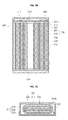
- FIG. 1B is a cross-sectional view of the battery of FIG. 1A taken along line 1A-1A.
- FIG. 1C is a cross-sectional view of the battery of FIG. 1A taken along line 1C-1C.
- a pouch-type lithium secondary battery 100 includes an electrode assembly 200, a pouch material 300 for accommodating the electrode assembly 200, a protective circuit module 400 for controlling the charge and discharge of the electrode assembly 200, and first and second moulding units 510 and 520 formed by hot melting.
- the electrode assembly 200 includes a first electrode plate 210 coated with a positive electrode active material, a second electrode plate 220 coated with a negative electrode active material, and a separator 230 positioned between the first electrode plate 210 and the second electrode plate 220 for preventing short circuits between the first electrode plate 210 and the second electrode plate 220 and to allow only lithium ions to move.
- a first electrode tab 215 operating as a positive electrode tab (commonly formed of aluminium (Al) though not limited thereto) is connected to the first electrode plate 210 and protrudes from the first electrode plate 210 by a desired length.
- a second electrode tab 225 operating as a negative electrode tab (commonly formed of nickel (Ni) though not limited thereto) is connected to the second electrode plate 220 and protrudes from the second electrode plate 220 by a desired length.
- An insulating tape 240 for preventing the first electrode tab 215, the second electrode tab 225, and the pouch material 300 from short circuiting can be further provided.
- the first electrode tab 215 and the second electrode tab 225 extend outside the pouch through one side of the pouch material 300 and are electrically connected to the protective circuit module 400.
- first and second insulating plates 251 and 255 can be attached to the top and bottom of the electrode assembly 200 to prevent the electrode assembly 200 from being directly connected to the pouch material 300.
- Nonlimiting examples of suitable materials for the positive electrode active material include chalcogenide compounds, for example, composite metal oxides such as LiCoO 2 , LiMn 2 O 4 , LiNiO 2 , LiNi1-xCoxO 2 (0 ⁇ x ⁇ 1), and LiMnO 2 .
- suitable negative electrode active materials include carbon (C) based materials, Si, Sn, tin oxides, composite tin alloys, transition metal oxides, lithium metal nitrides, or lithium metal oxides.
- One nonlimiting example of a suitable material for the positive electrode plate is aluminium (A1).
- One nonlimiting example of a suitable material for the negative electrode plate is copper (Cu).
- suitable materials for the separator include polyethylene (PE) and polypropylene (PP).
- the first electrode tab 215 and the second electrode tab 225 of the pouch-type lithium secondary battery 100 extend upward.
- the pouch material 300 has a first surface 310, a second surface 320, and a third surface 330.
- the first surface 310 includes a cavity for accommodating the electrode assembly 200 and is open in one direction.
- the second surface 320 is connected to the first surface 310 by a preformed first fold 340.
- the second surface 320 covers the open part of the first surface 310.
- the preformed fold 340 is parallel to a line along which the first electrode tab 215 and the second electrode tab 225 extend from the electrode assembly 200. That is, the preformed fold 340 may be positioned on the side of the electrode assembly 200.
- the third surface 330 is long enough to wrap around the first and second surfaces 310 and 320, respectively, defining the electrode assembly accommodating unit at least once. That is, the pouch material 300 is generally tube-shaped so that two adjacent surfaces (i.e. the first and second surfaces 310 and 320 respectively) are folded by the preformed fold 340 to form an electrode assembly accommodating unit 315A for accommodating the electrode assembly 200 and so that the other surface (i.e. the third surface 330) surrounds the electrode assembly accommodating unit 315A at least once. That is, the third surface 330 functions as a wing for surrounding the electrode assembly accommodating unit 315A.
- the pouch material 300 includes a core layer 300a, a thermal fusion layer 300b formed on top of the core layer 300a, and an insulating layer 300c formed on the bottom of the core layer 300a.
- a suitable material for the core layer 300a is aluminium (Al).
- a suitable material for the thermal fusion layer 300b is denatured polypropylene (PP) (i.e. a polymer resin such as casted polypropylene (CPP) for functioning as an adhesive layer).
- PP polypropylene
- CPP casted polypropylene
- suitable materials for the insulating layer 300c include resins such as nylon and polyethyleneterephthalate (PET).
- the protective circuit module 400 positioned on the pouch material 300 is electrically connected to the first electrode tab 215 and the second electrode tab 225 of the electrode assembly 200 to control charge and discharge and to control erroneous operation of the electrode assembly 200. For example, when over-current flows from the electrode assembly 200, the protective circuit module 400 intercepts the over-current.
- the protective circuit module 400 includes an input and output terminal 410 on its outside surface for the charge and discharge of the pouch-type lithium secondary battery 100. Although not shown in the drawings, the protective circuit module 400 may include a variety of common protective circuits.
- the first and second moulding units 510 and 520 are moulded by a hot-melting method using a hot melt adhesive.
- the first and second moulding units 510 and 520 help the pouch material 300 remain generally tube-shaped.
- a thermal fusion adhesive in which a non-volatile, incombustible, and thermoplastic resin that is 100% solid at room temperature is used as the hot melt adhesive for the first and second moulding units 510 and 520.
- water or other solvent
- the thermal fusion adhesive is liquefied at high temperature and then applied to the object to be adhered.
- the thermal fusion adhesive acquires adhesive force after compression, cooling and solidification, which occurs within a few seconds.
- Nonlimiting examples of suitable hot melts for the first and second moulding units 510 and 520 include ethylene-vinyl acetate (EVA) copolymer-based materials, polyamide-based materials, polyester-based materials, rubber-based materials, and polyurethane-based materials.
- EVA ethylene-vinyl acetate
- the first moulding unit 510 is formed by moulding the portion of the protective circuit module 400 settled on the pouch material 300 using the hot melt so that the input and output terminal 410 of the protective circuit module 400 is exposed. That is, the first moulding unit 510 covers the outside of the protective circuit module on the pouch material 300 but leaves the input and output terminal 410 exposed.
- the packing processes are performed using the pouch material 300 in the inventive pouch-type lithium secondary battery 100. This leaves the bottom of the pouch-type lithium secondary battery 100 vulnerable to external shock (when compared to other parts of the battery). Accordingly, a second moulding unit 520 is moulded by hot melting to the bottom of the pouch.
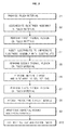
- FIG. 2 is a flowchart illustrating a method of manufacturing a pouch-type lithium secondary battery according to one embodiment of the present invention.
- one method of manufacturing a pouch-type lithium secondary battery according to an embodiment of the present invention includes first providing a pouch material (step S1). The method further includes accommodating an electrode assembly in an electrode assembly accommodating cavity of the pouch material (step S2). In addition, the method includes performing a first thermal fusion process on the pouch material (step S3). The method further includes injecting an electrolyte into the pouch to impregnate the electrode assembly with the electrolyte (step S4). Also, the method further includes performing a second thermal fusion process on the pouch material (step S5). The method further includes performing initial charge and discharge to collect gas (step S6).
- the method includes performing a third thermal fusion process on the pouch material (step S7).
- the method further includes attaching a protective circuit module (step S8).
- the method further includes wrapping the pouch material around the electrode assembly (step S9).
- the method includes hot-melting the pouch material, thereby manufacturing a pouch-type lithium secondary battery according to one embodiment of the present invention (step S10).
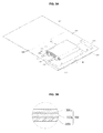
- FIGs. 3A to 3F illustrate a method of manufacturing a pouch-type lithium secondary battery according to one embodiment of the present invention.
- FIG. 3B is an enlarged sectional view of area 3B in FIG. 3A.
- a method of manufacturing the pouch-type lithium secondary battery according to one embodiment of the present invention will be described with reference to FIGs. 2 and 3A through 3F.
- a pouch material is provided as illustrated in FIG. 3A.
- the pouch material 300 includes a first surface 310, a second surface 320, and a third surface 330 connected to each other by first and second preformed folds 340 and 345.
- the first surface 310 includes a cavity 315 for receiving an electrode assembly 200, and a gas collecting space 317.
- the second surface 320 is connected to the first surface 310 and covers the first surface 310 to form an electrode assembly accommodating unit 315A.
- the third surface 330 is long enough to wrap around the electrode assembly accommodating unit 315A at least once.
- the line along which the cavity 315 and the gas collecting space 317 extend may be parallel to the first and second preformed folds 340 and 345.
- the pouch material 300 includes a core layer 300a formed of a metal such as aluminium (Al), a thermal fusion layer 300b formed on the top surface of the core layer, and an insulating layer 300c formed on the bottom surface of the core layer 300a.
- a suitable material for the core layer 300a is aluminium (Al).
- a suitable material for the thermal fusion layer 300b is a denatured polypropylene (PP) (i.e. a polymer resin such as casted polypropylene (CPP) to function as the adhesive layer).
- PP denatured polypropylene
- CPP casted polypropylene
- suitable materials for the insulating layer 300c include resins such as nylon or polyethyleneterephthalate (PET).
- the cavity 315 for accommodating the electrode assembly 200 and the gas collecting space 317 are formed in the first surface 310.
- the cavity 315 and the gas collecting space 317 can alternatively be formed in either the second surface 320 or the third surface 330.
- step S2 (accommodating the electrode assembly in the pouch material), as illustrated in FIGs. 3A and 3B, the electrode assembly 200 is provided and accommodated in the cavity 315 of the first surface 310 of the pouch material 300.
- the first electrode tab 215 and the second electrode tab 225 of the electrode assembly 200 protrude from the pouch by a desired length and in the direction opposite the gas collecting space 317. For purposes of this description, it is assumed that the first electrode tab 215 and the second electrode tab 225 protrude upward relative to the pouch-type lithium secondary battery.
- the order in which the electrode assembly 200 and the pouch material 300 are provided is not limited to the above, and the electrode assembly 200 can be provided first, followed by providing the pouch material 300.
- first and second insulating plates can be attached to the top and bottom of the electrode assembly 200 to prevent the electrode assembly 200 from being directly connected to the pouch material 300.
- step S3 (performing the first thermal fusion process on the pouch material), as illustrated in FIG. 3C, after accommodating the electrode assembly 200 in the cavity 315, the pouch material 300 is folded along the preformed fold 340 so that the first surface 310 is covered with the second surface 320. The first thermal fusion process is then performed to connect the first and second surfaces 310 and 320 together.
- the preformed fold 340 may be parallel to the line along which the first and second electrode tabs 215 and 225 of the electrode assembly 200 extend. That is, the preformed fold 340 may be positioned on the side of the electrode assembly 200.
- the first thermal fusion process is performed on the pouch material 300 at the edge of the cavity 315 to form the gas collecting space 317 next to the cavity 315.
- a first through hole 350 is created at the edge of the gas collecting space 317.
- the first through hole 350 connects the gas collecting space 317 to the outside of the pouch material 300.
- a second through hole 360 is created between the cavity 315 and the gas collecting space 317. The second through hole 360 connects the cavity 315 and the gas collecting space 317.
- the first thermal fusion process is performed to connect the first surface 310 and the second surface 320 of the pouch material to each other so that the cavity 315 operates as the electrode assembly accommodating unit 315A.
- step S4 injecting the electrolyte to impregnate the electrode assembly with the electrolyte
- the pouch is positioned such that the gas collecting space 317 is at the top and the electrolyte is injected through the first through hole 350 under vacuum so that the electrode assembly 200 is impregnated with the electrolyte.
- step S5 (performing the second thermal fusion process on the pouch material), as illustrated in FIG. 3D, after injecting the electrolyte and impregnating the electrode assembly 200 with the electrolyte, the second thermal fusion process is performed to seal the first through hole 350 of the pouch material 300.
- step S6 performing initial charge and discharge to collect gas
- step S6 after performing the second thermal fusion process on the first through hole 350, initial charge and discharge is performed with the gas collecting space 317 positioned at the top of the pouch.
- a gas is generated by the electrode assembly 200. This gas is collected in the gas collecting space 317 through the second through hole 360.
- the gas collecting space 317 is positioned opposite the direction in which the first and second electrode tabs 215 and 225 extend, there exist few obstacles to the movement of the gas. Therefore, effective degassing can be performed.
- step S7 (performing the third thermal fusion process on the pouch material), as illustrated in FIG. 3E, after performing initial charge and discharge and collecting the gas in the gas collecting space 317, the third thermal fusion process is performed to seal the second through hole 360.
- the gas collecting space 317 is cut away from the electrode assembly accommodating unit 315 a to form a pouch bare cell.
- step S8 attaching the protective circuit module
- the protective circuit module 400 is electrically attached to the first and second electrode tabs 215 and 225 which protrude above the pouch bare cell.
- the protective circuit module 400 may include a variety of protective circuits to control the charge and discharge and to control the erroneous operation of the electrode assembly 200.
- the protective circuit module 400 includes an input and output terminal 410 for charge and discharge of the electrode assembly 200.
- step S9 wrapping the pouch material around the electrode assembly
- the third surface 330 of the pouch material 300 is wrapped around the outer circumference of the pouch bare cell at least once.
- the outer circumference of the electrode assembly accommodating unit 315A (which includes an electrode assembly 200 within the cavity 315 in the first surface 310 of the pouch material 300 covered by the second surface 320 of the pouch material 300) is surrounded at least once by the third surface 330 of the pouch material 300.
- step S8 attaching the protective circuit module
- step S9 wrapping the pouch material around the electrode assembly
- step S10 hot-melting the pouch material to complete the pouch-type lithium battery
- the top where the protective circuit module 400 of the pouch bare cell is attached
- the bottom of the pouch bare cell are hot-melted with a hot melt adhesive to form the first and second moulding units 510 and 520 and thereby complete the pouch-type lithium secondary battery 100.
- the input and output terminal 410 of the protective circuit module 400 may be hot-melted so as not to be exposed to the outside.
- the top and bottom of the pouch material 300 are hot melted to preserve the form in which the pouch material is wrapped around the electrode assembly.
- the electrolyte is injected in a direction parallel to the direction in which the first and second electrode tabs 215 and 225 of the electrode assembly 200 extends. This makes it possible to effectively impregnate the electrode assembly 200 with the electrolyte. That is, the electrolyte can effectively penetrate the gaps between the first electrode plate 210, the second electrode plate 220 and the separator 230 of the electrode assembly 200.
- the gas collecting space 317 is positioned on the side opposite the direction in which the first and second electrode tabs 215 and 225 extend. Therefore, during initial charge and discharge to collect the gas, there are few obstacles to the movement of the gas, making it possible to effectively perform degassing.
Abstract

Description
- The present invention relates to a pouch-type lithium secondary battery and a method of manufacturing the same. More particularly, the invention is directed to a pouch-type lithium secondary battery using a part of the pouch material to perform packing processes, so that an additional packing case is not needed, thereby simplifying the packing processes.
- Recently, compact and light electrical and electronic apparatuses such as mobile telephones, notebook computers, and camcorders have been actively developed and produced. Battery packs are built-in to these portable electrical and electronic apparatuses, enabling the apparatuses to operate when other power sources are not available. The built-in battery packs each include at least one battery for outputting a uniform level voltage to drive the portable electrical and electronic apparatus for a desired period of time.
- For economical reasons, secondary batteries (which can be charged and discharged) have recently been used as the battery packs. Secondary batteries include lithium secondary batteries such as lithium (Li) batteries and lithium ion (Li-ion) batteries, as well as nickel-cadmium (Ni-Cd) batteries and nickel-hydrogen (Ni-MH) batteries.
- In particular, since lithium secondary batteries commonly operate at a voltage of 3.6 V (which is three times greater than the operation voltages of the Ni-Cd batteries and Ni-H batteries that are widely used as power sources for portable electronic apparatuses), and since the energy density per unit weight of lithium ion secondary batteries is high, the use of lithium ion secondary batteries has rapidly increased.
- In lithium secondary batteries, lithium-based oxides are used as the positive electrode active materials, and carbon materials are used as the negative electrode active materials. In general, lithium ion secondary batteries are divided into liquid electrolyte batteries and polymer electrolyte batteries according to the kind of electrolyte used. Batteries using liquid electrolytes are referred to as lithium ion batteries, and batteries using polymer electrolytes are referred to as lithium polymer batteries. Also, lithium secondary batteries are manufactured in various shapes, such as cylinders, polygons, and pouches.
- In general, in pouch-type lithium secondary batteries, the pouch material is commonly formed of multiple layers of metal foil and a synthetic resin layer which cover the metal foil layers.
- When pouch-type lithium secondary batteries are used, the weight of the battery (in comparison with cylinder- and polygon-type lithium secondary batteries in which metal cans are used) can be significantly reduced. Therefore, in order to reduce the weight of lithium secondary batteries, pouch-type lithium secondary batteries have been developed.
- In general, in pouch-type lithium secondary batteries, an electrode assembly is placed on the bottom surface of the pouch material (which includes a space for accommodating the electrode assembly). The bottom surface is then covered with the top surface of the pouch material and the pouch is sealed to form a pouch bare cell. Accessories, such as protective circuit modules, are attached to the pouch bare cell to form a pouch core pack and the pouch core pack is built-in to an additional battery packing case.
- However, when the additional battery packing case of the pouch-type lithium secondary battery is used as described above, processes are complicated, and there are limitations on the improvement of the productivity per unit time of the pouch-type lithium secondary battery.
- Also, since an additional battery packing case is used, reductions in the manufacturing cost of the pouch-type lithium secondary battery are limited.
- In one embodiment of the present invention, a pouch-type lithium secondary battery is provided in which packing processes are performed using a part of the pouch material without using an additional packing case, thereby simplifying the packing processes.
- In another embodiment of the present invention, a method of manufacturing the pouch-type lithium secondary battery is provided.
- In one embodiment of the present invention, a pouch-type lithium secondary battery comprises an electrode assembly comprising a first electrode plate to which a first electrode tab is attached, a second electrode plate to which a second electrode tab is attached, a separator positioned between the first electrode plate and the second electrode plate, and a pouch having a pouch material. The pouch material has a first surface, a second surface, and a third surface. The first and second surfaces are adjacent one another and are separated by a preformed first fold in the pouch material, and form the electrode assembly accommodating unit (which accommodates the electrode assembly). The third surface is adjacent the second surface and extends from the second surface to wrap around the electrode assembly accommodating unit at least once. The preformed fold separating the first and second surfaces is parallel to the line along which the first and second electrode tabs extend out of the pouch.
- The first surface of the pouch material includes a cavity for accommodating the electrode assembly, and the second surface (which is connected to the first surface by the preformed fold) covers the cavity of the first surface. By this structure, the pouch material forms the electrode assembly accommodating unit.
- In one embodiment, the pouch-type lithium secondary battery may further include a protective circuit module including an input and output terminal for performing charge and discharge. The input and output terminal may be provided on the outside surface of the protective circuit module. The protective circuit module is electrically connected to the first and second electrode tabs to control charge and discharge and to control erroneous operation of the electrode assembly.
- In another embodiment, the pouch-type lithium secondary battery may further include a first moulding unit for moulding the top of the pouch material so that the input and output terminal on the outside surface of the protective circuit module is exposed.
- In another embodiment, the pouch-type lithium secondary battery may further include a second moulding unit for protecting the bottom of the pouch material.
- One nonlimiting method of forming the first and/or the second moulding unit is using a hot melt adhesive. The hot melt adhesive may be a thermal fusion adhesive. Nonlimiting examples of suitable thermal fusion adhesives include ethylene-vinyl acetate (EVA) copolymer-based materials, polyamide-based materials, polyester-based materials, rubber-based materials, and polyurethane-based materials.
- In one embodiment, the electrode assembly can further include first and second insulating plates on the top and bottom of the electrode assembly.
- In one embodiment, the pouch material may include a core layer, a thermal fusion layer formed on the core layer, and an insulating layer formed under the core layer. One nonlimiting example of a suitable material for the core layer is aluminium (Al). One nonlimiting example of a suitable material for the thermal fusion layer is denatured polypropylene (PP). Nonlimiting examples of suitable materials for the insulating layer include nylon and polyethyleneterephthalate (PET).
- In another embodiment of the present invention, a method of manufacturing a pouch-type lithium secondary battery comprises: (a) providing a pouch material, wherein the pouch material has first, second and third surfaces, the first surface having an electrode assembly accommodating space and a gas collecting space; (b) providing an electrode assembly comprising a first electrode plate to which a first electrode tab is attached, a second electrode plate to which a second electrode tab is attached, and a separator positioned between the first electrode plate and the second electrode plate; (c) positioning the electrode assembly in the electrode assembly accommodating space so that the first and second electrode tabs face protrude from the electrode assembly accommodating space in a direction opposite the gas collecting space, (d) folding the second surface of the pouch material along a preformed fold between the first and second surfaces to seal the pouch material and form a pouch bare cell, and (d) wrapping the third surface of the pouch material around the pouch bare cell at least once.
- In one embodiment, the preformed fold connecting the first and second surfaces may be parallel to the line along which the first and second electrode tabs extend out of the pouch.
- In another embodiment, the method of manufacturing the pouch-type lithium secondary battery may further include electrically connecting a protective circuit module to the first and second electrode tabs on the outer surface of the pouch material. The protective circuit module includes an input and output terminal on its outside surface.
- In one embodiment, the method of manufacturing the pouch-type lithium secondary battery may further include forming a first moulding unit on the top of the pouch material so that the input and output terminal formed on the outside surface of the protective circuit module is exposed. In another embodiment, the method of manufacturing the pouch-type lithium secondary battery may further include forming a second moulding unit on the bottom of the pouch material using a hot melt adhesive.
- In one embodiment, step (d) above includes performing a first thermal fusion process to fold the surfaces of the pouch material. A first through hole is then formed for connecting the electrode assembly accommodating unit and the gas collecting space to the outside. A second through hole is then formed for connecting the cavity accommodating the electrode assembly to the gas collecting space. An electrolyte is then injected through the first through hole to impregnate the electrode assembly with the electrolyte. A second thermal fusion process is then performed to seal the first through hole. Initial charge and discharge is then performed to collect gas in the gas collecting space. A third thermal fusion process is then performed to seal the second through hole. After performing the third thermal fusion to seal the second through hole, a fourth thermal fusion may be performed to remove the gas collecting space.
- These and/or other aspects and advantages of the present invention will become more apparent by reference to the following detailed description when considered in conjunction with the accompanying drawings, in which:
- FIG. 1A is a perspective view of a pouch-type lithium secondary battery according to one embodiment of the present invention;
- FIG. 1B is a cross-sectional view of the battery of FIG. 1A, taken along
line 1A-1A; - FIG. 1C is a cross-sectional view of the battery of FIG. 1A, taken along line 1C-1C of FIG. 1A;
- FIG. 2 is a flowchart illustrating a method of manufacturing a pouch-type lithium secondary battery according to one embodiment of the present invention;
- FIG. 3A is a schematic depicting a step in a method of manufacturing a pouch-type lithium battery according to one embodiment of the present invention;
- FIG. 3B is an exploded view of
area 3B in FIG. 3A; - FIG. 3C is a schematic illustrating another step in the method of manufacturing a pouch-type lithium battery illustrated in FIG. 3A;
- FIG. 3D is a schematic illustrating yet another step in the method of manufacturing a pouch-type lithium battery illustrated in FIG. 3A;
- FIG. 3E is a schematic illustrating still another step in the method of manufacturing a pouch-type lithium battery illustrated in FIG. 3A; and
- FIG. 3F is a perspective view of a pouch-type lithium battery manufactured by the process depicted in FIGs. 3A through 3E.
- Hereinafter, exemplary embodiments of the present invention will be described in detail with reference to the accompanying drawings. In the drawings, like reference numerals refer to like elements.
- FIG. 1A is a perspective view of a pouch-type lithium secondary battery according to one embodiment of the present invention. FIG. 1B is a cross-sectional view of the battery of FIG. 1A taken along
line 1A-1A. FIG. 1C is a cross-sectional view of the battery of FIG. 1A taken along line 1C-1C. - Referring to FIGs. 1A through 1C, a pouch-type lithium
secondary battery 100 according to one embodiment of the present invention includes anelectrode assembly 200, apouch material 300 for accommodating theelectrode assembly 200, aprotective circuit module 400 for controlling the charge and discharge of theelectrode assembly 200, and first andsecond moulding units - The
electrode assembly 200 includes afirst electrode plate 210 coated with a positive electrode active material, asecond electrode plate 220 coated with a negative electrode active material, and aseparator 230 positioned between thefirst electrode plate 210 and thesecond electrode plate 220 for preventing short circuits between thefirst electrode plate 210 and thesecond electrode plate 220 and to allow only lithium ions to move. Afirst electrode tab 215 operating as a positive electrode tab (commonly formed of aluminium (Al) though not limited thereto) is connected to thefirst electrode plate 210 and protrudes from thefirst electrode plate 210 by a desired length. Asecond electrode tab 225 operating as a negative electrode tab (commonly formed of nickel (Ni) though not limited thereto) is connected to thesecond electrode plate 220 and protrudes from thesecond electrode plate 220 by a desired length. Aninsulating tape 240 for preventing thefirst electrode tab 215, thesecond electrode tab 225, and thepouch material 300 from short circuiting can be further provided. Thefirst electrode tab 215 and thesecond electrode tab 225 extend outside the pouch through one side of thepouch material 300 and are electrically connected to theprotective circuit module 400. If desired, first and second insulatingplates electrode assembly 200 to prevent theelectrode assembly 200 from being directly connected to thepouch material 300. - Nonlimiting examples of suitable materials for the positive electrode active material include chalcogenide compounds, for example, composite metal oxides such as LiCoO2, LiMn2O4, LiNiO2, LiNi1-xCoxO2(0<x<1), and LiMnO2. Nonlimiting examples of suitable negative electrode active materials include carbon (C) based materials, Si, Sn, tin oxides, composite tin alloys, transition metal oxides, lithium metal nitrides, or lithium metal oxides. One nonlimiting example of a suitable material for the positive electrode plate is aluminium (A1). One nonlimiting example of a suitable material for the negative electrode plate is copper (Cu). Nonlimiting examples of suitable materials for the separator include polyethylene (PE) and polypropylene (PP).
- According to one embodiment of the present invention, the
first electrode tab 215 and thesecond electrode tab 225 of the pouch-type lithiumsecondary battery 100 extend upward. - In one embodiment of the present invention, the
pouch material 300 has afirst surface 310, asecond surface 320, and athird surface 330. - The
first surface 310 includes a cavity for accommodating theelectrode assembly 200 and is open in one direction. Thesecond surface 320 is connected to thefirst surface 310 by a preformedfirst fold 340. Thesecond surface 320 covers the open part of thefirst surface 310. - In one embodiment, the preformed
fold 340 is parallel to a line along which thefirst electrode tab 215 and thesecond electrode tab 225 extend from theelectrode assembly 200. That is, the preformedfold 340 may be positioned on the side of theelectrode assembly 200. - In one embodiment, the
third surface 330 is long enough to wrap around the first andsecond surfaces pouch material 300 is generally tube-shaped so that two adjacent surfaces (i.e. the first andsecond surfaces fold 340 to form an electrodeassembly accommodating unit 315A for accommodating theelectrode assembly 200 and so that the other surface (i.e. the third surface 330) surrounds the electrodeassembly accommodating unit 315A at least once. That is, thethird surface 330 functions as a wing for surrounding the electrodeassembly accommodating unit 315A. - The
pouch material 300 includes acore layer 300a, athermal fusion layer 300b formed on top of thecore layer 300a, and an insulatinglayer 300c formed on the bottom of thecore layer 300a. One nonlimiting example of a suitable material for thecore layer 300a is aluminium (Al). One nonlimiting example of a suitable material for thethermal fusion layer 300b is denatured polypropylene (PP) (i.e. a polymer resin such as casted polypropylene (CPP) for functioning as an adhesive layer). Nonlimiting examples of suitable materials for the insulatinglayer 300c include resins such as nylon and polyethyleneterephthalate (PET). - The
protective circuit module 400 positioned on thepouch material 300 is electrically connected to thefirst electrode tab 215 and thesecond electrode tab 225 of theelectrode assembly 200 to control charge and discharge and to control erroneous operation of theelectrode assembly 200. For example, when over-current flows from theelectrode assembly 200, theprotective circuit module 400 intercepts the over-current. Theprotective circuit module 400 includes an input andoutput terminal 410 on its outside surface for the charge and discharge of the pouch-type lithiumsecondary battery 100. Although not shown in the drawings, theprotective circuit module 400 may include a variety of common protective circuits. - In one embodiment, the first and
second moulding units second moulding units pouch material 300 remain generally tube-shaped. - In one embodiment, a thermal fusion adhesive in which a non-volatile, incombustible, and thermoplastic resin that is 100% solid at room temperature is used as the hot melt adhesive for the first and
second moulding units - Nonlimiting examples of suitable hot melts for the first and
second moulding units - The
first moulding unit 510 is formed by moulding the portion of theprotective circuit module 400 settled on thepouch material 300 using the hot melt so that the input andoutput terminal 410 of theprotective circuit module 400 is exposed. That is, thefirst moulding unit 510 covers the outside of the protective circuit module on thepouch material 300 but leaves the input andoutput terminal 410 exposed. - The packing processes are performed using the
pouch material 300 in the inventive pouch-type lithiumsecondary battery 100. This leaves the bottom of the pouch-type lithiumsecondary battery 100 vulnerable to external shock (when compared to other parts of the battery). Accordingly, asecond moulding unit 520 is moulded by hot melting to the bottom of the pouch. - FIG. 2 is a flowchart illustrating a method of manufacturing a pouch-type lithium secondary battery according to one embodiment of the present invention. Referring to FIG. 2, one method of manufacturing a pouch-type lithium secondary battery according to an embodiment of the present invention includes first providing a pouch material (step S1). The method further includes accommodating an electrode assembly in an electrode assembly accommodating cavity of the pouch material (step S2). In addition, the method includes performing a first thermal fusion process on the pouch material (step S3). The method further includes injecting an electrolyte into the pouch to impregnate the electrode assembly with the electrolyte (step S4). Also, the method further includes performing a second thermal fusion process on the pouch material (step S5). The method further includes performing initial charge and discharge to collect gas (step S6). In addition, the method includes performing a third thermal fusion process on the pouch material (step S7). The method further includes attaching a protective circuit module (step S8). Also, the method further includes wrapping the pouch material around the electrode assembly (step S9). Finally, the method includes hot-melting the pouch material, thereby manufacturing a pouch-type lithium secondary battery according to one embodiment of the present invention (step S10).
- FIGs. 3A to 3F illustrate a method of manufacturing a pouch-type lithium secondary battery according to one embodiment of the present invention. FIG. 3B is an enlarged sectional view of
area 3B in FIG. 3A. Hereinafter, a method of manufacturing the pouch-type lithium secondary battery according to one embodiment of the present invention will be described with reference to FIGs. 2 and 3A through 3F. - First, in step S1 a pouch material is provided as illustrated in FIG. 3A. As shown, the
pouch material 300 includes afirst surface 310, asecond surface 320, and athird surface 330 connected to each other by first and secondpreformed folds - The
first surface 310 includes a cavity 315 for receiving anelectrode assembly 200, and agas collecting space 317. Thesecond surface 320 is connected to thefirst surface 310 and covers thefirst surface 310 to form an electrodeassembly accommodating unit 315A. Thethird surface 330 is long enough to wrap around the electrodeassembly accommodating unit 315A at least once. - In one embodiment, the line along which the cavity 315 and the
gas collecting space 317 extend may be parallel to the first and secondpreformed folds - In one embodiment, the
pouch material 300 includes acore layer 300a formed of a metal such as aluminium (Al), athermal fusion layer 300b formed on the top surface of the core layer, and an insulatinglayer 300c formed on the bottom surface of thecore layer 300a. One nonlimiting example of a suitable material for thecore layer 300a is aluminium (Al). One nonlimiting example of a suitable material for thethermal fusion layer 300b is a denatured polypropylene (PP) (i.e. a polymer resin such as casted polypropylene (CPP) to function as the adhesive layer). Nonlimiting examples of suitable materials for the insulatinglayer 300c include resins such as nylon or polyethyleneterephthalate (PET). - The cavity 315 for accommodating the
electrode assembly 200 and thegas collecting space 317 are formed in thefirst surface 310. However, the cavity 315 and thegas collecting space 317 can alternatively be formed in either thesecond surface 320 or thethird surface 330. - In step S2 (accommodating the electrode assembly in the pouch material), as illustrated in FIGs. 3A and 3B, the
electrode assembly 200 is provided and accommodated in the cavity 315 of thefirst surface 310 of thepouch material 300. Thefirst electrode tab 215 and thesecond electrode tab 225 of theelectrode assembly 200 protrude from the pouch by a desired length and in the direction opposite thegas collecting space 317. For purposes of this description, it is assumed that thefirst electrode tab 215 and thesecond electrode tab 225 protrude upward relative to the pouch-type lithium secondary battery. - The order in which the
electrode assembly 200 and thepouch material 300 are provided is not limited to the above, and theelectrode assembly 200 can be provided first, followed by providing thepouch material 300. - Although not shown in the drawings, in one embodiment, first and second insulating plates can be attached to the top and bottom of the
electrode assembly 200 to prevent theelectrode assembly 200 from being directly connected to thepouch material 300. - In step S3 (performing the first thermal fusion process on the pouch material), as illustrated in FIG. 3C, after accommodating the
electrode assembly 200 in the cavity 315, thepouch material 300 is folded along the preformedfold 340 so that thefirst surface 310 is covered with thesecond surface 320. The first thermal fusion process is then performed to connect the first andsecond surfaces - The preformed
fold 340 may be parallel to the line along which the first andsecond electrode tabs electrode assembly 200 extend. That is, the preformedfold 340 may be positioned on the side of theelectrode assembly 200. - The first thermal fusion process is performed on the
pouch material 300 at the edge of the cavity 315 to form thegas collecting space 317 next to the cavity 315. - A first through
hole 350 is created at the edge of thegas collecting space 317. The first throughhole 350 connects thegas collecting space 317 to the outside of thepouch material 300. A second throughhole 360 is created between the cavity 315 and thegas collecting space 317. The second throughhole 360 connects the cavity 315 and thegas collecting space 317. - After accommodating the
electrode assembly 200 in the cavity 315, the first thermal fusion process is performed to connect thefirst surface 310 and thesecond surface 320 of the pouch material to each other so that the cavity 315 operates as the electrodeassembly accommodating unit 315A. - In step S4 (injecting the electrolyte to impregnate the electrode assembly with the electrolyte) the pouch is positioned such that the
gas collecting space 317 is at the top and the electrolyte is injected through the first throughhole 350 under vacuum so that theelectrode assembly 200 is impregnated with the electrolyte. - Since the first through
hole 350 into which the electrolyte is injected is parallel to the line along which the first andsecond electrode tabs electrode assembly 200 extend, few obstacles exist through which the electrolyte must pass before impregnating theelectrode assembly 200. This enables effective impregnation of theelectrode assembly 200 with the electrolyte. That is, the electrolyte can effectively penetrate the gaps between thefirst electrode plate 210, thesecond electrode plate 220 and theseparator 230 of theelectrode assembly 200. In step S5 (performing the second thermal fusion process on the pouch material), as illustrated in FIG. 3D, after injecting the electrolyte and impregnating theelectrode assembly 200 with the electrolyte, the second thermal fusion process is performed to seal the first throughhole 350 of thepouch material 300. - In step S6 (performing initial charge and discharge to collect gas), as illustrated in FIG. 3D, after performing the second thermal fusion process on the first through
hole 350, initial charge and discharge is performed with thegas collecting space 317 positioned at the top of the pouch. During initial charge and discharge, a gas is generated by theelectrode assembly 200. This gas is collected in thegas collecting space 317 through the second throughhole 360. - Since the
gas collecting space 317 is positioned opposite the direction in which the first andsecond electrode tabs - In step S7 (performing the third thermal fusion process on the pouch material), as illustrated in FIG. 3E, after performing initial charge and discharge and collecting the gas in the
gas collecting space 317, the third thermal fusion process is performed to seal the second throughhole 360. - Then, the
gas collecting space 317 is cut away from the electrode assembly accommodating unit 315 a to form a pouch bare cell. - In step S8 (attaching the protective circuit module), after performing the third thermal fusion process and removing the
gas collecting space 317, theprotective circuit module 400 is electrically attached to the first andsecond electrode tabs - The
protective circuit module 400 may include a variety of protective circuits to control the charge and discharge and to control the erroneous operation of theelectrode assembly 200. Theprotective circuit module 400 includes an input andoutput terminal 410 for charge and discharge of theelectrode assembly 200. - In step S9 (wrapping the pouch material around the electrode assembly), after attaching the
protective circuit module 400, thethird surface 330 of thepouch material 300 is wrapped around the outer circumference of the pouch bare cell at least once. - That is, the outer circumference of the electrode
assembly accommodating unit 315A (which includes anelectrode assembly 200 within the cavity 315 in thefirst surface 310 of thepouch material 300 covered by thesecond surface 320 of the pouch material 300) is surrounded at least once by thethird surface 330 of thepouch material 300. - The order of step S8 (attaching the protective circuit module) and step S9 (wrapping the pouch material around the electrode assembly) is not limited to the above. In one embodiment, step S8 (attaching the protective circuit module) can be performed after stepS9 (wrapping the pouch material around the electrode assembly).
- In step S10 (hot-melting the pouch material to complete the pouch-type lithium battery), as illustrated in FIG. 3F, after the pouch bare cell is surrounded at least once by the
third surface 330 of thepouch material 300, the top (where theprotective circuit module 400 of the pouch bare cell is attached) and the bottom of the pouch bare cell are hot-melted with a hot melt adhesive to form the first andsecond moulding units secondary battery 100. - In one embodiment, the input and
output terminal 410 of theprotective circuit module 400 may be hot-melted so as not to be exposed to the outside. - In one embodiment, the top and bottom of the
pouch material 300 are hot melted to preserve the form in which the pouch material is wrapped around the electrode assembly. - In the above-described inventive pouch-type lithium secondary batteries, additional packing cases are not used. Rather, a part of the
pouch material 300 itself surrounds the electrodeassembly accommodating unit 315A so that the packing processes are performed by simply wrapping the pouch material around the electrodeassembly accommodating unit 315A, thereby simplifying the packing processes. - Since additional packing cases are not used, manufacturing costs of the inventive pouch-type lithium secondary batteries are reduced.
- In the process of injecting the electrolyte to impregnate the
electrode assembly 200 with the electrolyte, the electrolyte is injected in a direction parallel to the direction in which the first andsecond electrode tabs electrode assembly 200 extends. This makes it possible to effectively impregnate theelectrode assembly 200 with the electrolyte. That is, the electrolyte can effectively penetrate the gaps between thefirst electrode plate 210, thesecond electrode plate 220 and theseparator 230 of theelectrode assembly 200. - The
gas collecting space 317 is positioned on the side opposite the direction in which the first andsecond electrode tabs - As described above, in the inventive batteries, since the packing processes are performed using a part of the pouch material without using additional packing cases, the packing processes of the inventive pouch-type lithium batteries are simplified, as is a method of manufacturing the same. Although certain exemplary embodiments of the present invention have been shown and described, it will be appreciated by those skilled in the art that changes may be made to the described embodiments without departing from the principle, spirit and scope of the invention, as defined in the appended claims.
Claims (19)
- A pouch-type lithium secondary battery (100) comprising:an electrode assembly (200) comprising:a first electrode plate (210) and a first electrode tab (215) attached to the first electrode plate (210),a second electrode plate (220) and a second electrode tab (225) attached to the second electrode plate (220), anda separator (230) positioned between the first electrode plate (210) and the second electrode plate (220); anda pouch material (300) comprising a first surface (310), a second surface (320), and a third surface (330), wherein the first and second surfaces (310, 320) of the pouch material (300) are folded together along a first fold (340) to form an electrode assembly accommodating unit (315A) for accommodating the electrode assembly (200), and
wherein the third surface (330) of the pouch material (300) wraps around the electrode assembly accommodating unit (315A) at least once, the first fold (340) being parallel to a line along which the first and second electrode tabs (215, 225) extend from the electrode assembly (200). - The pouch-type lithium secondary battery (100) according to claim 1, wherein the electrode assembly accommodating unit (315A) comprises a cavity (215) in the first surface (310) of the pouch material (300) for accommodating the electrode assembly (200), and wherein the second surface (320) of the pouch material (300) covers the cavity (315) in the first surface (310).
- The pouch-type lithium secondary battery (100) according to claim 1 or 2, further comprising a protective circuit module (400) comprising an input and output terminal (410), the protective circuit module (400) being electrically connected to the first and second electrode tabs (215, 225).
- The pouch-type lithium secondary battery (100) according to claim 3, wherein the protective circuit module (400) is adapted to control charge, discharge and erroneous operation of the electrode assembly (200).
- The pouch-type lithium secondary battery (100) according to claim 3 or 4, further comprising a first moulding unit (510) positioned on the pouch material (300) covering the protective circuit module (400), wherein the input and output terminal (410) of the protective circuit module (400) is exposed.
- The pouch-type lithium secondary battery (100) according to one of proceeding claims, further comprising a second moulding unit (520) positioned on a side of the pouch material (300) opposite a side where the first and second electrode tabs (215, 225) are positioned.
- The pouch-type lithium secondary battery (100) according to one of claims 5 or 6, wherein at least one of the first moulding unit (510) and the second moulding unit (520) is formed using a hot melt adhesive.
- The pouch-type lithium secondary battery (100) according to claim 7, wherein the hot melt adhesive comprises a thermal fusion adhesive.
- The pouch-type lithium secondary battery as claimed in claim 8, wherein the hot melt adhesive is selected from the group consisting of ethylene-vinyl acetate (EVA) copolymer-based materials, polyamide-based materials, polyester-based materials, rubber-based materials, and polyurethane-based materials.
- The pouch-type lithium secondary battery (100) according to one of proceeding claims, wherein the electrode assembly further comprises first and second insulating plates (251, 255) positioned on top and bottom parts of the electrode assembly (200).
- The pouch-type lithium secondary battery (100) according to one of proceeding claims, wherein the pouch material (300) comprises:a core layer (300a);a thermal fusion layer (300b) on the core layer (300a); andan insulating layer (300c) under the core layer (300a).
- The pouch-type lithium secondary battery (100) according to claim 11, wherein the core layer (300a) comprises aluminium (A1), the thermal fusion layer (300b) comprises denatured polypropylene (PP), and the insulating layer (300c) comprises a material selected from the group consisting of nylon and polyethyleneterephthalate (PET).
- A method of manufacturing a pouch-type lithium secondary battery (100), the method comprising:(a) providing a pouch material (300) comprising a first surface (310), a second surface (320), and a third surface (330), wherein the first surface (310) comprises a cavity (315) for accommodating an electrode assembly (200) and a gas collecting space (317);(b) providing an electrode assembly (200) comprising a first electrode plate (210), a first electrode tab (215) attached to the first electrode plate (210), a second electrode plate (320), a second electrode tab (225) attached to the second electrode plate (220), and a separator (230) positioned between the first electrode plate (210) and the second electrode plate (220);(c) accommodating the electrode assembly (200) in the cavity (215) in the first surface (310) of the pouch material (300) so that the first electrode tab (215) and the second electrode tab (225) extend in a direction opposite the gas collecting space (217);(d) folding the second surface (320) of the pouch material (300) along a first fold (340) between the first and second surfaces (310, 320) to cover the cavity (315) and gas collecting space (317) and thereby form a pouch bare cell; and(e) wrapping the third surface (330) of the pouch material (300) around the pouch bare cell at least once.
- The method of manufacturing the pouch-type lithium secondary battery (100) according to claim 13, wherein the first fold (340) is parallel to a line along which the first and second electrode tabs (215, 225) extend.
- The method of manufacturing the pouch-type lithium secondary battery (100) according to claim 13 or 14, further comprising electrically connecting a protective circuit module (400) to the first and second electrode tabs (215, 225), wherein the protective circuit module (400) comprises an input and output terminal (410).
- The method of manufacturing the pouch-type lithium secondary battery (100) according to claim 15, further comprising forming a first moulding unit (510) on a side of the pouch material (300) where the protective circuit module (400) is connected, wherein the first moulding unit (510) is formed so that the input and output terminal (410)of the protective circuit module (400) is exposed.
- The method of manufacturing the pouch-type lithium secondary battery (100) according to claims 15 or 16, further comprising forming a second moulding unit (520) on a side of the pouch material (300) opposite the position of the first moulding unit (510), wherein at least one of the first moulding unit (519) and the second moulding unit (520) is formed using a hot melt adhesive.
- The method of manufacturing the pouch-type lithium secondary battery (100) according to one of proceeding claims 13 to 17, wherein step (d) comprises:folding the second surface (320) of the pouch material (300) along the first fold (340) to cover the cavity (315) and gas collecting space (317) in the first surface (310) of the pouch material (300);performing a first thermal fusion process to connect the first and second surfaces (310, 320) of the pouch material (300);forming a first through hole (350) connecting the gas collecting space (317) to an exterior of the pouch material (300);forming a second through hole (360) connecting the cavity (315) to the gas collecting space (317);injecting an electrolyte through the first through hole (250) to impregnate the electrode assembly (200) accommodated in the cavity (315) with the electrolyte;performing a second thermal fusion process to seal the first through hole (350);performing an initial charge and discharge to collect a gas in the gas collecting space (317); andperforming a third thermal fusion process to seal the second through hole (360).
- The method of manufacturing a pouch-type lithium secondary battery (100) according to claim 18, further comprising removing the gas collecting space (317).
Applications Claiming Priority (1)
| Application Number | Priority Date | Filing Date | Title |
|---|---|---|---|
| KR1020050090780A KR100709881B1 (en) | 2005-09-28 | 2005-09-28 | Pouch type Li Secondary Battery and Method of fabrcating the same |
Publications (3)
| Publication Number | Publication Date |
|---|---|
| EP1772914A2 true EP1772914A2 (en) | 2007-04-11 |
| EP1772914A3 EP1772914A3 (en) | 2007-10-24 |
| EP1772914B1 EP1772914B1 (en) | 2008-11-12 |
Family
ID=37401461
Family Applications (1)
| Application Number | Title | Priority Date | Filing Date |
|---|---|---|---|
| EP06120961A Expired - Fee Related EP1772914B1 (en) | 2005-09-28 | 2006-09-20 | Pouch-type lithium secondary battery and fabrication method thereof |
Country Status (4)
| Country | Link |
|---|---|
| US (1) | US7976981B2 (en) |
| EP (1) | EP1772914B1 (en) |
| KR (1) | KR100709881B1 (en) |
| DE (1) | DE602006003608D1 (en) |
Cited By (6)
| Publication number | Priority date | Publication date | Assignee | Title |
|---|---|---|---|---|
| EP2680337A1 (en) * | 2012-06-25 | 2014-01-01 | Samsung SDI Co., Ltd. | Rechargeable battery |
| EP2648259A4 (en) * | 2010-12-02 | 2016-12-07 | Lg Chemical Ltd | Method for deaerating secondary battery using centrifugal force |
| US10183825B2 (en) | 2010-02-26 | 2019-01-22 | Duracell U.S. Operations, Inc. | Winding method |
| DE102017223231A1 (en) | 2017-12-19 | 2019-06-19 | Thyssenkrupp Ag | Degassing device and degassing method for a battery cell |
| WO2022094632A1 (en) * | 2020-11-02 | 2022-05-05 | Medtronic, Inc. | Foil pack |
| WO2022098431A1 (en) * | 2020-11-09 | 2022-05-12 | Medtronic, Inc. | Energy storage device assemblies |
Families Citing this family (29)
| Publication number | Priority date | Publication date | Assignee | Title |
|---|---|---|---|---|
| JP4559406B2 (en) * | 2005-12-29 | 2010-10-06 | 三星エスディアイ株式会社 | Pouch-type battery |
| KR100876455B1 (en) * | 2006-07-31 | 2008-12-29 | 주식회사 엘지화학 | Pouch type secondary battery with unsealed surplus |
| KR100928119B1 (en) | 2007-10-30 | 2009-11-24 | 삼성에스디아이 주식회사 | Printed Circuit Board and Secondary Battery Using the Same |
| JP5573474B2 (en) * | 2010-08-06 | 2014-08-20 | ソニー株式会社 | Battery manufacturing method |
| KR101271920B1 (en) * | 2011-06-17 | 2013-06-05 | 삼성에스디아이 주식회사 | Secondary battery |
| US8709645B2 (en) | 2011-07-01 | 2014-04-29 | Apple Inc. | Battery pouch sheet edge insulation |
| USD669435S1 (en) * | 2011-07-26 | 2012-10-23 | Research In Motion Limited | Electronic device battery label |
| USD669436S1 (en) * | 2011-07-26 | 2012-10-23 | Research In Motion Limited | Electronic device battery label |
| US9343716B2 (en) * | 2011-12-29 | 2016-05-17 | Apple Inc. | Flexible battery pack |
| EP2860809B1 (en) * | 2012-06-11 | 2017-10-18 | Nissan Motor Co., Ltd | Manufacturing method and manufacturing device of secondary battery |
| US9812680B2 (en) | 2012-08-30 | 2017-11-07 | Apple Inc. | Low Z-fold battery seal |
| TW201414046A (en) * | 2012-09-19 | 2014-04-01 | Dijiya Energy Saving Technology Inc | Structure of lithium battery |
| KR20150030861A (en) | 2013-09-13 | 2015-03-23 | 주식회사 엘지화학 | Pouched type case, battery cell and manufacturing method of battery cell |
| US9593969B2 (en) | 2013-12-27 | 2017-03-14 | Apple Inc. | Concealed electrical connectors |
| US9479007B1 (en) | 2014-02-21 | 2016-10-25 | Apple Inc. | Induction charging system |
| US20150255776A1 (en) | 2014-03-06 | 2015-09-10 | Apple Inc. | Battery Pack System |
| US9455582B2 (en) | 2014-03-07 | 2016-09-27 | Apple Inc. | Electronic device and charging device for electronic device |
| KR102197996B1 (en) | 2014-05-20 | 2021-01-04 | 삼성에스디아이 주식회사 | Method for manufacturing secondary battery and secondary battery manufactured by the same |
| US10033064B2 (en) | 2014-06-24 | 2018-07-24 | Duracell U.S. Operations, Inc. | Method and apparatus for forming a wound structure |
| US9917335B2 (en) | 2014-08-28 | 2018-03-13 | Apple Inc. | Methods for determining and controlling battery expansion |
| US10637017B2 (en) | 2016-09-23 | 2020-04-28 | Apple Inc. | Flexible battery structure |
| US10686228B2 (en) | 2016-12-14 | 2020-06-16 | Pacesetter, Inc. | Pouch battery for use in implantable electronic devices |
| WO2019045447A1 (en) * | 2017-08-29 | 2019-03-07 | 주식회사 엘지화학 | Secondary battery, manufacturing method therefor, and pressing block for manufacturing secondary battery |
| KR102555751B1 (en) * | 2017-10-17 | 2023-07-14 | 주식회사 엘지에너지솔루션 | Gas Dischargeable Pouch-Type Case for Secondary Battery |
| KR102164254B1 (en) * | 2017-11-15 | 2020-10-12 | 주식회사 엘지화학 | The Secondary Battery And The Method For Manufacturing Thereof, The Pouch For Secondary Battery And The Method For Manufacturing Thereof |
| US10992005B2 (en) | 2018-12-06 | 2021-04-27 | Robert Bosch Battery Systems Llc | Deep pouch cell and method of manufacturing same |
| US11296386B2 (en) * | 2019-02-06 | 2022-04-05 | GS Yuasa Lithium Power Inc. | Expandable electrochemical cell effluent containment device and corresponding systems and methods |
| KR20240034020A (en) * | 2022-09-06 | 2024-03-13 | 주식회사 엘지에너지솔루션 | Formation apparatus of pouch type battery cell |
| KR20240034016A (en) * | 2022-09-06 | 2024-03-13 | 주식회사 엘지에너지솔루션 | Formation method of pouch type battery cell |
Citations (2)
| Publication number | Priority date | Publication date | Assignee | Title |
|---|---|---|---|---|
| US20020106555A1 (en) | 2001-02-08 | 2002-08-08 | Eveready Battery Company, Inc. | Appatraus and method for assembling a flexible battery that is electrolyte-tight |
| EP1473785A2 (en) | 2003-05-01 | 2004-11-03 | Sony Corporation | Battery pack and method for producing battery pack |
Family Cites Families (41)
| Publication number | Priority date | Publication date | Assignee | Title |
|---|---|---|---|---|
| US5591540A (en) | 1995-06-26 | 1997-01-07 | Motorola, Inc. | Packaging for an electrochemical device and device using same |
| US6461757B1 (en) | 1997-03-19 | 2002-10-08 | Asahi Kasei Kogyo Kabushiki Kaisha | Non-aqueous battery of a thin configuration |
| US5871865A (en) | 1997-05-15 | 1999-02-16 | Valence Technology, Inc. | Methods of fabricating electrochemical cells |
| US5916704A (en) * | 1997-10-10 | 1999-06-29 | Ultralife Batteries | Low pressure battery vent |
| EP0975031B2 (en) | 1998-02-05 | 2011-11-02 | Dai Nippon Printing Co., Ltd. | Sheet for cell case and cell device |
| US6048638A (en) * | 1998-05-29 | 2000-04-11 | Motorola, Inc. | Flexible battery |
| US6379838B1 (en) * | 1999-04-14 | 2002-04-30 | Alcatel | Cell package |
| US6296967B1 (en) | 1999-09-24 | 2001-10-02 | Electrofuel Inc. | Lithium battery structure incorporating lithium pouch cells |
| KR100346378B1 (en) | 1999-11-16 | 2002-08-01 | 삼성에스디아이 주식회사 | Lithium polymer battery pack |
| JP4529207B2 (en) | 1999-11-30 | 2010-08-25 | ソニー株式会社 | Non-aqueous electrolyte battery |
| US6426163B1 (en) * | 1999-12-21 | 2002-07-30 | Alcatel | Electrochemical cell |
| JP4598214B2 (en) | 1999-12-21 | 2010-12-15 | 京セラ株式会社 | battery pack |
| JP2001250516A (en) | 2000-03-06 | 2001-09-14 | Mitsubishi Chemicals Corp | Battery |
| JP2001307712A (en) * | 2000-04-19 | 2001-11-02 | Nec Mobile Energy Kk | Encapsulated battery |
| JP2002100326A (en) | 2000-09-22 | 2002-04-05 | Gs-Melcotec Co Ltd | Flat-type battery |
| JP3614767B2 (en) | 2000-10-20 | 2005-01-26 | 松下電器産業株式会社 | Method for forming exterior body of electrical product |
| JP3751834B2 (en) * | 2001-02-05 | 2006-03-01 | 日本電気株式会社 | Film seal type non-aqueous electrolyte battery |
| JP5023411B2 (en) | 2001-03-30 | 2012-09-12 | 株式会社Gsユアサ | Battery device |
| JP3929839B2 (en) | 2001-06-28 | 2007-06-13 | 松下電器産業株式会社 | Batteries and battery packs |
| US20030082445A1 (en) | 2001-10-25 | 2003-05-01 | Smith W. Novis | Battery pouch |
| US6515449B1 (en) * | 2001-11-21 | 2003-02-04 | Ngk Spark Plug Co., Ltd | Battery with lead/nugget protection insert |
| US7563535B2 (en) | 2002-02-06 | 2009-07-21 | Sony Corporation | Battery pack with insulating film sheath material and method of producing the same |
| JP3736529B2 (en) | 2002-02-06 | 2006-01-18 | ソニー株式会社 | Battery pack |
| JP4589596B2 (en) | 2002-03-22 | 2010-12-01 | パナソニック株式会社 | Battery pack |
| KR100858798B1 (en) | 2002-06-17 | 2008-09-17 | 삼성에스디아이 주식회사 | Battery and method for making it |
| JP2004047334A (en) | 2002-07-12 | 2004-02-12 | Nissan Motor Co Ltd | Battery pack |
| JP2004087219A (en) | 2002-08-26 | 2004-03-18 | Sumitomo Electric Ind Ltd | Packaging bag, and nonaqueous electrolyte battery using the same |
| TWI300637B (en) * | 2002-09-27 | 2008-09-01 | Sony Corp | Battery pack and method for producing same |
| CN1411081A (en) | 2002-11-15 | 2003-04-16 | 中信国安盟固利电源技术有限公司 | Flexible package liquid state lithium ion battery |
| US20040149375A1 (en) * | 2003-02-05 | 2004-08-05 | Shun-Ming Huang | Method for encapsulating a secondary battery |
| KR20040107868A (en) * | 2003-06-14 | 2004-12-23 | 삼성에스디아이 주식회사 | Pouched-type lithium secondary battery |
| KR20040110156A (en) * | 2003-06-18 | 2004-12-31 | 삼성에스디아이 주식회사 | Pouch type secondary battery with safty vent |
| KR100544119B1 (en) | 2003-06-24 | 2006-01-23 | 삼성에스디아이 주식회사 | Pouched-type lithium secondary battery |
| KR20030074562A (en) | 2003-08-28 | 2003-09-19 | 지엠에스전자(주) | The resin moulding system for Li-ion battery |
| JP4378499B2 (en) | 2003-08-28 | 2009-12-09 | パイオニクス株式会社 | Thin pack battery |
| KR100561298B1 (en) | 2004-01-13 | 2006-03-15 | 삼성에스디아이 주식회사 | Secondary Battery |
| KR100664113B1 (en) | 2004-02-28 | 2007-01-04 | 엘지전자 주식회사 | Soft cell internal type battery |
| KR100561310B1 (en) | 2004-05-31 | 2006-03-15 | 삼성에스디아이 주식회사 | Lithium polymer battery pack and separation method between core pack and case |
| KR100601511B1 (en) | 2004-09-24 | 2006-07-19 | 삼성에스디아이 주식회사 | Lithium polymer battery and its manufacturing method |
| KR100686807B1 (en) | 2005-03-25 | 2007-02-26 | 삼성에스디아이 주식회사 | Polymer battery pack and manufacturing method the same |
| KR100686817B1 (en) * | 2005-03-28 | 2007-02-26 | 삼성에스디아이 주식회사 | Pouch type Li Secondary Battery and Method of fabrcating the same |
-
2005
- 2005-09-28 KR KR1020050090780A patent/KR100709881B1/en not_active IP Right Cessation
-
2006
- 2006-09-20 DE DE602006003608T patent/DE602006003608D1/en active Active
- 2006-09-20 EP EP06120961A patent/EP1772914B1/en not_active Expired - Fee Related
- 2006-09-28 US US11/540,855 patent/US7976981B2/en not_active Expired - Fee Related
Patent Citations (2)
| Publication number | Priority date | Publication date | Assignee | Title |
|---|---|---|---|---|
| US20020106555A1 (en) | 2001-02-08 | 2002-08-08 | Eveready Battery Company, Inc. | Appatraus and method for assembling a flexible battery that is electrolyte-tight |
| EP1473785A2 (en) | 2003-05-01 | 2004-11-03 | Sony Corporation | Battery pack and method for producing battery pack |
Cited By (7)
| Publication number | Priority date | Publication date | Assignee | Title |
|---|---|---|---|---|
| US10183825B2 (en) | 2010-02-26 | 2019-01-22 | Duracell U.S. Operations, Inc. | Winding method |
| EP2648259A4 (en) * | 2010-12-02 | 2016-12-07 | Lg Chemical Ltd | Method for deaerating secondary battery using centrifugal force |
| EP2680337A1 (en) * | 2012-06-25 | 2014-01-01 | Samsung SDI Co., Ltd. | Rechargeable battery |
| US9431636B2 (en) | 2012-06-25 | 2016-08-30 | Samsung Sdi Co., Ltd. | Rechargeable battery |
| DE102017223231A1 (en) | 2017-12-19 | 2019-06-19 | Thyssenkrupp Ag | Degassing device and degassing method for a battery cell |
| WO2022094632A1 (en) * | 2020-11-02 | 2022-05-05 | Medtronic, Inc. | Foil pack |
| WO2022098431A1 (en) * | 2020-11-09 | 2022-05-12 | Medtronic, Inc. | Energy storage device assemblies |
Also Published As
| Publication number | Publication date |
|---|---|
| KR20070035876A (en) | 2007-04-02 |
| US7976981B2 (en) | 2011-07-12 |
| EP1772914A3 (en) | 2007-10-24 |
| US20070072071A1 (en) | 2007-03-29 |
| DE602006003608D1 (en) | 2008-12-24 |
| KR100709881B1 (en) | 2007-04-20 |
| EP1772914B1 (en) | 2008-11-12 |
Similar Documents
| Publication | Publication Date | Title |
|---|---|---|
| EP1772914B1 (en) | Pouch-type lithium secondary battery and fabrication method thereof | |
| KR100686817B1 (en) | Pouch type Li Secondary Battery and Method of fabrcating the same | |
| US8852791B2 (en) | Pouch type lithium secondary battery with sleeve and method of fabricating | |
| EP1708295B1 (en) | Pouch type lithium secondary battery and method of fabricating the same | |
| US8778529B2 (en) | Lithium secondary battery | |
| KR100659856B1 (en) | Pouch Type Li Secondary Battery | |
| KR100624967B1 (en) | Pouch type lithium secondary battery and the method of fabricating the same | |
| KR100646528B1 (en) | Pouch type Lithium Secondary Battery and Method of using the same | |
| KR101243560B1 (en) | Pouch type Lithium Rechargeable Battery | |
| KR100659845B1 (en) | Pouch type Li Secondary Battery and method for fabricating the same | |
| KR100686818B1 (en) | Pouch type Li Secondary Battery and Method of fabrcating the same | |
| KR100624977B1 (en) | Pouch Type Li Secondary Battery | |
| KR100601510B1 (en) | Pouch Type Li Secondary Battery and Method of fabricating the same | |
| KR100686819B1 (en) | Pouch type Li Secondary Battery and Method of fabrcating the same | |
| KR100659887B1 (en) | Manufacturing method of secondary battery | |
| KR100591443B1 (en) | Pouch-type lithium secondary battery and manufacturing method thereof | |
| KR100686820B1 (en) | Pouch type Li Secondary Battery and Method of fabrcating the same | |
| KR100670421B1 (en) | Pouch type Li Secondary Battery and Method of fabrcating the same | |
| KR100686802B1 (en) | Battery Pack Case, Pouch-type Li Secondary Battery with the Pack Case | |
| KR100591439B1 (en) | Manufacturing method of pouch type lithium secondary battery | |
| KR100731425B1 (en) | Pouch type Lithium Secondary Battery |
Legal Events
| Date | Code | Title | Description |
|---|---|---|---|
| PUAI | Public reference made under article 153(3) epc to a published international application that has entered the european phase |
Free format text: ORIGINAL CODE: 0009012 |
|
| 17P | Request for examination filed |
Effective date: 20060920 |
|
| AK | Designated contracting states |
Kind code of ref document: A2 Designated state(s): AT BE BG CH CY CZ DE DK EE ES FI FR GB GR HU IE IS IT LI LT LU LV MC NL PL PT RO SE SI SK TR |
|
| AX | Request for extension of the european patent |
Extension state: AL BA HR MK YU |
|
| PUAL | Search report despatched |
Free format text: ORIGINAL CODE: 0009013 |
|
| AK | Designated contracting states |
Kind code of ref document: A3 Designated state(s): AT BE BG CH CY CZ DE DK EE ES FI FR GB GR HU IE IS IT LI LT LU LV MC NL PL PT RO SE SI SK TR |
|
| AX | Request for extension of the european patent |
Extension state: AL BA HR MK YU |
|
| RIC1 | Information provided on ipc code assigned before grant |
Ipc: H01M 2/36 20060101ALI20070920BHEP Ipc: H01M 6/50 20060101ALI20070920BHEP Ipc: H01M 10/34 20060101ALI20070920BHEP Ipc: H01M 2/10 20060101ALI20070920BHEP Ipc: H01M 2/02 20060101AFI20070131BHEP Ipc: H01M 10/04 20060101ALI20070920BHEP Ipc: H01M 2/04 20060101ALI20070920BHEP |
|
| GRAP | Despatch of communication of intention to grant a patent |
Free format text: ORIGINAL CODE: EPIDOSNIGR1 |
|
| GRAS | Grant fee paid |
Free format text: ORIGINAL CODE: EPIDOSNIGR3 |
|
| AKX | Designation fees paid |
Designated state(s): DE FR GB |
|
| GRAA | (expected) grant |
Free format text: ORIGINAL CODE: 0009210 |
|
| AK | Designated contracting states |
Kind code of ref document: B1 Designated state(s): DE FR GB |
|
| REG | Reference to a national code |
Ref country code: GB Ref legal event code: FG4D |
|
| REF | Corresponds to: |
Ref document number: 602006003608 Country of ref document: DE Date of ref document: 20081224 Kind code of ref document: P |
|
| PLBE | No opposition filed within time limit |
Free format text: ORIGINAL CODE: 0009261 |
|
| STAA | Information on the status of an ep patent application or granted ep patent |
Free format text: STATUS: NO OPPOSITION FILED WITHIN TIME LIMIT |
|
| 26N | No opposition filed |
Effective date: 20090813 |
|
| REG | Reference to a national code |
Ref country code: FR Ref legal event code: PLFP Year of fee payment: 10 |
|
| PGFP | Annual fee paid to national office [announced via postgrant information from national office to epo] |
Ref country code: DE Payment date: 20150916 Year of fee payment: 10 Ref country code: GB Payment date: 20150916 Year of fee payment: 10 |
|
| PGFP | Annual fee paid to national office [announced via postgrant information from national office to epo] |
Ref country code: FR Payment date: 20150825 Year of fee payment: 10 |
|
| REG | Reference to a national code |
Ref country code: DE Ref legal event code: R119 Ref document number: 602006003608 Country of ref document: DE |
|
| GBPC | Gb: european patent ceased through non-payment of renewal fee |
Effective date: 20160920 |
|
| REG | Reference to a national code |
Ref country code: FR Ref legal event code: ST Effective date: 20170531 |
|
| PG25 | Lapsed in a contracting state [announced via postgrant information from national office to epo] |
Ref country code: FR Free format text: LAPSE BECAUSE OF NON-PAYMENT OF DUE FEES Effective date: 20160930 Ref country code: DE Free format text: LAPSE BECAUSE OF NON-PAYMENT OF DUE FEES Effective date: 20170401 Ref country code: GB Free format text: LAPSE BECAUSE OF NON-PAYMENT OF DUE FEES Effective date: 20160920 |