EP1772896A2 - Lamp - Google Patents
Lamp Download PDFInfo
- Publication number
- EP1772896A2 EP1772896A2 EP06121828A EP06121828A EP1772896A2 EP 1772896 A2 EP1772896 A2 EP 1772896A2 EP 06121828 A EP06121828 A EP 06121828A EP 06121828 A EP06121828 A EP 06121828A EP 1772896 A2 EP1772896 A2 EP 1772896A2
- Authority
- EP
- European Patent Office
- Prior art keywords
- electrically conductive
- power supply
- supply section
- lamp
- potting compound
- Prior art date
- Legal status (The legal status is an assumption and is not a legal conclusion. Google has not performed a legal analysis and makes no representation as to the accuracy of the status listed.)
- Granted
Links
Images
Classifications
-
- H—ELECTRICITY
- H01—ELECTRIC ELEMENTS
- H01J—ELECTRIC DISCHARGE TUBES OR DISCHARGE LAMPS
- H01J9/00—Apparatus or processes specially adapted for the manufacture, installation, removal, maintenance of electric discharge tubes, discharge lamps, or parts thereof; Recovery of material from discharge tubes or lamps
- H01J9/38—Exhausting, degassing, filling, or cleaning vessels
-
- H—ELECTRICITY
- H01—ELECTRIC ELEMENTS
- H01J—ELECTRIC DISCHARGE TUBES OR DISCHARGE LAMPS
- H01J5/00—Details relating to vessels or to leading-in conductors common to two or more basic types of discharge tubes or lamps
- H01J5/50—Means forming part of the tube or lamps for the purpose of providing electrical connection to it
- H01J5/54—Means forming part of the tube or lamps for the purpose of providing electrical connection to it supported by a separate part, e.g. base
- H01J5/62—Connection of wires protruding from the vessel to connectors carried by the separate part
-
- H—ELECTRICITY
- H01—ELECTRIC ELEMENTS
- H01K—ELECTRIC INCANDESCENT LAMPS
- H01K1/00—Details
- H01K1/42—Means forming part of the lamp for the purpose of providing electrical connection, or support for, the lamp
- H01K1/46—Means forming part of the lamp for the purpose of providing electrical connection, or support for, the lamp supported by a separate part, e.g. base, cap
Definitions
- the invention relates to a lamp according to the preamble of patent claim 1.
- Such lamps are for example from the EP-A 1 006 551 known.
- This publication discloses a halogen incandescent lamp for a motor vehicle headlamp with an enclosed by a glass lamp vessel incandescent and two power supply wires for the filament, which protrude from the sealed end of the lamp vessel.
- the sealed end of the lamp vessel is fixed in a lamp base provided with two electrical terminals for the lamp.
- the power supply wires are each connected to one of the electrical terminals of the lamp by welding.
- the lamp according to the invention comprises at least one lamp enclosed by a lamp vessel and at least one first power supply section for supplying energy to the at least one lamp and a lamp base, which is equipped with at least one second power supply section for supplying power to the at least one lamp, wherein an electrically conductive potting compound or an electrically conductive adhesive or an electrically conductive solder is provided, by means of which or an electrically conductive connection between the at least one first power supply section and the at least one second power supply section is produced.
- the lamp base of the lamp according to the invention preferably has at least one container into which the at least one first power supply section and the at least one second power supply section project, wherein the container is at least as far filled with the electrically conductive potting compound or the electrically conductive adhesive or the electrically conductive solder in that the at least one first power supply section and the at least one second power supply section are wetted by the electrically conductive potting compound or the electrically conductive adhesive or the electrically conductive solder.
- the at least one container a defined space within the lamp cap is provided with a predetermined volume for the electrically conductive potting compound or the electrically conductive adhesive or the electrically conductive solder.
- the at least one container To produce the electrical contact between the at least one first power supply section and the at least one second power supply section, it is sufficient for the at least one container to be so far connected to the electrically conductive potting compound or the electrically conductive potting compound To fill adhesive or the electrically conductive solder that the at least one first power supply section and the at least one second power supply section of the electrically conductive potting compound or the electrically conductive adhesive or the electrically conductive solder are wetted.
- the electrical contact between the at least one first power supply section and the at least one second power supply section is thereby directly via the electrically conductive potting compound or the electrically conductive adhesive or the electrically conductive solder and / or, if the at least one container has metallic walls over the made of metallic walls.
- the at least one first power supply section and the at least one second power supply section are arranged without contact with each other in order to provide sufficient clearance for the at least one first power supply section during the above-mentioned adjustment of the at least one light source.
- the distance between the first and second current supply sections is as small as possible.
- the surfaces of the first and / or second power supply sections may be partially or completely coated with a high-conductivity metal.
- the first and / or second power supply sections may be partially silver plated, gold plated, copper plated, chrome plated or nickel plated.
- the at least one first power supply section may have a cup-like end into which projects the at least one second power supply section and with the electrically conductive potting compound or electrically conductive adhesive or the electrically conductive solder is at least partially filled.
- the at least one second power supply section may have a cup-like end into which the at least one first power supply section protrudes and which is at least partially filled with the electrically conductive potting compound or the electrically conductive adhesive or the electrically conductive solder.
- the at least one first power supply section may have a hole or a cut into which the at least one second power supply section protrudes and which is at least partially covered with the electrically conductive potting compound or the electrically conductive adhesive or the electrically conductive solder, to keep the current density in the electrically conductive potting compound or the electrically conductive adhesive or the electrically conductive solder low.
- the at least one second power supply section may have a hole or a cutout into which the at least one first power supply section protrudes, and that with the electrically conductive potting compound or the electrically conductive adhesive or the electrically conductive solder is at least partially covered.
- the at least one first power supply section and the at least one second power supply section do not necessarily have to be arranged without contact. In order to keep the contact resistance between them as small as possible, they can also touch.
- the first or second current supply section projecting into the cup-like end or into the hole or the cutout can touch the cup wall or the edge of the hole or the cutout.
- the lamp base in the region of the at least one container is equipped with means which enable inductive heating of the electrically conductive potting compound arranged in the container or the electrically conductive adhesive or the electrically conductive solder by means of electromagnetic fields.
- the encapsulated in the lamp base electrically conductive potting compound or the electrically conductive adhesive or the electrically conductive solder can be heated without contact to cure the electrically conductive potting compound or the electrically conductive adhesive or to melt the electrically conductive solder.
- the side walls of the aforementioned container are formed by a metal sleeve.
- an electrical current can be induced in the side walls around the electrically conductive potting compound or the electrically conductive adhesive arranged in the container or electrically to heat conductive solder inductively.
- the side walls of the container may be made of plastic and formed integrally with a plastic base part.
- a metal ring may be embedded in the side walls in order to inductively heat the electrically conductive potting compound arranged in the container or the electrically conductive adhesive or the electrically conductive solder.
- On the metal ring can also be dispensed with, since due to their electrical conductivity in the electrically conductive potting compound or the electrically conductive adhesive or the electrically conductive solder itself a current for heating the potting compound or the adhesive or the solder can be induced.
- connection between the at least one first power supply section and the at least one second power supply section and the electrically conductive potting compound or the electrically conductive adhesive or the electrically conductive solder is gas-tight to prevent the ingress of moisture into the lamp cap.
- the second power supply portions of the lamp base have projecting ends formed as electrical terminals of the lamp.
- the at least one first power supply section is preferably a power supply section protruding from the lamp vessel, in particular a power supply wire protruding from the lamp vessel.
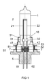
- first embodiment of the invention is a halogen incandescent lamp, which is intended for use as a light source in a motor vehicle headlight.
- This lamp has a lamp envelope 1 made of quartz glass, which is sealed at one end by means of a Quetschfußes 10.
- an incandescent filament 2 is arranged, the filament outlets 21, 22 in each case via a molybdenum foil 31 or 32 embedded in a gas-tight manner in the presser foot 10 with a protruding from the presser foot 10, molybdenum existing power supply wire 41 and 42 are connected.
- the presser foot 10 of the lamp vessel 1 is fixed in a metallic holder part 51 of the lamp cap 5.
- the metallic holder part 51 is anchored in a plastic part 52 of the lamp cap 5. From the plastic base part 52 protrude two metallic contact lugs 61, 62, which are formed as stamped sheet metal parts and are each electrically connected to one of the power supply wires 41 and 42, respectively.
- the electrically conductive connection between the first power supply wire 41 and the first metallic contact lug 61 is produced by means of an electrically conductive potting compound 7, which is arranged in a first hollow cylindrical container 81.
- the first metallic contact lug 61 protrudes through the bottom into the interior of the first container 81, while the first power supply wire 41 protrudes from above into the interior of the first container 81, so that the first power supply wire 41 and the first contact lug 61 at a distance of approx.
- the electrically conductive potting compound 7 wets both the first contact lug 61 and the first power supply wire 41 and fills the gap between the first power supply wire 41 and the first contact lug 61.
- the electrically conductive connection between the second power supply wire 42 and the second metal contact lug 62 is made by means of an electrically conductive potting compound 7, which is arranged in a second hollow cylindrical container 82.
- the second metallic contact lug 62 projects through the bottom into the interior of the second Container 82, while the second power supply wire 42 protrudes from above into the interior of the second container 82, so that the second power supply wire 42 and the second contact lug 62 are arranged at a distance of about 1 millimeter in the second container 82.
- the electrically conductive potting compound 7 wets both the second contact lug 62 and the second power supply wire 42 and fills the gap between the second power supply wire 42 and the second contact lug 62.
- the walls of the two containers 81, 82 for the potting compound 7 are integrally formed with the plastic base part 52, for example as a plastic injection molded part.
- the potting compounds 7 in the containers 81, 82 are arranged electrically isolated from each other.
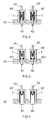
- FIG. 2 shows a cross section through the plastic base part 52 in the region of the connection between the power supply wires 41, 42 and the metallic contact lugs 61, 62 according to the second embodiment of the invention.
- This second embodiment differs from the first embodiment of the invention described above only in that the side walls of the two containers for the potting compound 7 are each formed by a metal tube 81 'and 82', one end of which is injected into the plastic base part 52.
- the first and second embodiments are the same.
- FIG. 3 shows a cross section through the plastic base part 52 in the region of the connection between the power supply wires 41, 42 and the metallic contact lugs 61, 62 according to the third embodiment of the invention.
- This third embodiment differs from the second embodiment only in that the contact lugs 61, 62 each have a cup-like end 611, 621, into which the power supply wires 41, 42 protrude.
- the cup-like ends 611, 621 are filled with potting compound 7.
- FIG. 4 shows a cross section through the plastic base part 52 in the region of the connection between the power supply wires 41, 42 and the metallic contact lugs 61, 62 according to the fourth embodiment of the invention.
- This fourth embodiment differs from the second embodiment only in that the contact lugs 61, 62 each have a V-shaped cutout into which the power supply wires 41, 42 protrude.
- the V-shaped cutouts are filled with potting compound 7.
- the prefabricated first unit consisting of the sealed lamp vessel 1 arranged therein filament 2 and fixed on the pinch 10 holder member 51 with the prefabricated second unit consisting of the plastic base part 52, the contact lugs 61, 62 injected therein and the metal ring 53 injected therein, and the potting compound 7 arranged in the containers 81, 82 and 81 ', 82, so that the holder part 51 rests on the metal ring 53 and the power supply wires 41, 42 in the potting compound 7 in the respective container 81, 82 or 81 ', 82' dip.
- the metal base portions 51, 53 are aligned with each other so that the filament 2 is aligned with a reference plane defined by the metal ring 53, and welded together, and the potting compound 7 is cured by heating or by UV irradiation or in another suitable manner.
- the heating of the potting compound 7 can be effected either by heating the complete lamp in an oven or by only locally heating the potting compound inductively by means of electromagnetic fields.
- electrically conductive potting compound 7 for example, epoxy resins filled with silver, for example Epo-Tek H37MP or E3082 or polyimide adhesive, for example P1011 / P1011S, are suitable.
- the invention is not limited to the embodiments explained in more detail above.
- the invention can also be applied to other lamp types, for example to discharge lamps or to incandescent lamps with a tempered glass lamp vessel sealed without molybdenum foil embedding.
- the materials is merely to ensure that the material of the plastic base part 52 in the region of the containers 81, 82 and 81 ', 82' the temperatures during the curing of the electrically conductive potting compound or the adhesive 7 and the temperatures during melting of the electrically conductive Solder paste withstands.
- Suitable materials for the plastic base part 52 are the usual high-temperature thermoplastics such as PA, PPS, PEI, PSU, LCP, PBTP and PEEK.
- potting compound or adhesive masses based on epoxy, polyimide, silicone, or ceramic and metal composite adhesive are suitable.
- metallic contact lugs 61, 62 can be used as electrical terminals of the lamp and wires or the electrical connections can for example also be designed as a plug or have any other shape.
- the potting compound 7 can be arranged only in the cup-like ends 611, 621 or in the cutouts and the containers 81 ', 82' are dispensed with.
- the contact lugs 61, 62 and the power supply wires 41, 42 instead of the contact lugs 61, 62 and the power supply wires 41, 42 have cup-like ends or cutouts, in each of which one of the contact lugs 61, 62 protrudes.
Landscapes
- Engineering & Computer Science (AREA)
- Manufacturing & Machinery (AREA)
- Non-Portable Lighting Devices Or Systems Thereof (AREA)
- Vessels And Coating Films For Discharge Lamps (AREA)
- Fastening Of Light Sources Or Lamp Holders (AREA)
- Common Detailed Techniques For Electron Tubes Or Discharge Tubes (AREA)
Abstract
Description
Die Erfindung betrifft eine Lampe gemäß dem Oberbegriff des Patentanspruchs 1.The invention relates to a lamp according to the preamble of
Derartige Lampen sind beispielsweise aus der
Es ist Aufgabe der Erfindung, eine gattungsgemäße Lampe mit einer einfacher herstellbaren Verbindung zwischen den aus dem Lampengefäß herausragenden Stromzuführungen für die Leuchtmittel und den elektrischen Anschlüssen der Lampe bereitzustellen.It is an object of the invention to provide a generic lamp with a connection easier to produce between the protruding from the lamp vessel power supply lines for the lamps and the electrical terminals of the lamp.
Diese Aufgabe wird erfindungsgemäß durch die Merkmale des Patentanspruchs 1 gelöst. Besonders vorteilhafte Ausführungen der Erfindung sind in den abhängigen Patentansprüchen beschrieben.This object is achieved by the features of
Die erfindungsgemäße Lampe weist mindestens ein von einem Lampengefäß umschlossenes Leuchtmittel und mindestens einen ersten Stromzuführungsabschnitt zur Energieversorgung des mindestens einen Leuchtmittels sowie einen Lampensockel auf, der mit mindestens einem zweiten Stromzuführungsabschnitt zur Energieversorgung des mindestens einen Leuchtmittels ausgestattet ist, wobei eine elektrisch leitfähige Vergussmasse oder ein elektrisch leitfähiger Kleber oder ein elektrisch leitfähiges Lot vorgesehen ist, mittels der bzw. dem eine elektrisch leitende Verbindung zwischen dem mindestens einen ersten Stromzuführungsabschnitt und dem mindestens einen zweiten Stromzuführungsabschnitt hergestellt wird. Dadurch entfällt die vergleichsweise aufwändige Schweißverbindung zwischen dem ersten und zweiten Stromzuführungsabschnitt, die gemäß dem Stand der Technik über einen Durchbruch im Lampensockel mittels eines Lasers durchgeführt wird. Außerdem werden bei der erfindungsgemäßen Lampe während der Montage des Lampensockels durch die Justage des Leuchtmittels gegenüber vom Lampensockel definierten Referenzpunkten keine bleibenden Rückstellkräfte auf den mindestens einen ersten Stromzuführungsabschnitt verursacht, die zu mechanischen Spannungen in dem mindestens einen ersten Stromzuführungsabschnitt führen könnten, da der mindestens eine erste Stromzuführungsabschnitt nahezu frei innerhalb des Lampensockels ausgerichtet werden kann. Die elektrisch leitfähige Vergussmasse bzw. der elektrisch leitfähige Kleber bzw. das elektrisch leitfähige Lot üben während der oben genannten Justage des mindestens einen Leuchtmittels keine Rückstellkräfte auf den mindestens einen ersten Stromzuführungsabschnitt auf, weil sich die elektrisch leitfähige Vergussmasse bzw. der elektrisch leitfähige Kleber bzw. das elektrisch leitfähige Lot während dieses Prozesses noch im flüssigen Zustand befinden oder aber erst nach diesem Prozess in den dafür vorgesehenen Raum im Lampensockel eingebracht werden. Außerdem kann mittels der elektrisch leitfähigen Vergussmasse bzw. des elektrisch leitfähigen Klebers bzw. das elektrisch leitfähige Lot eine gute Wärmeableitung erzielt werden, um die thermische Belastung des Quetschfußes 10 zu reduzieren.The lamp according to the invention comprises at least one lamp enclosed by a lamp vessel and at least one first power supply section for supplying energy to the at least one lamp and a lamp base, which is equipped with at least one second power supply section for supplying power to the at least one lamp, wherein an electrically conductive potting compound or an electrically conductive adhesive or an electrically conductive solder is provided, by means of which or an electrically conductive connection between the at least one first power supply section and the at least one second power supply section is produced. This eliminates the comparatively complex welded connection between the first and second current supply section, which is carried out according to the prior art via a breakthrough in the lamp base by means of a laser. In addition, no permanent restoring forces on the at least one first power supply section caused in the lamp according to the invention by the adjustment of the lamp relative to the lamp base defined reference points, which could lead to mechanical stresses in the at least one first power supply section, since the at least one first Power supply section can be aligned almost freely within the lamp cap. During the above-mentioned adjustment of the at least one luminous means, the electrically conductive potting compound or the electrically conductive adhesive or the electrically conductive solder exerts no restoring forces on the at least one first current supply section, because the electrically conductive potting compound or the electrically conductive adhesive or the electrically conductive solder during this process are still in the liquid state or are introduced only after this process in the space provided in the lamp base. In addition, good heat dissipation can be achieved by means of the electrically conductive potting compound or of the electrically conductive adhesive or the electrically conductive solder in order to reduce the thermal load on the squeezing
Vorzugsweise weist der Lampensockel der erfindungsgemäßen Lampe mindestens ein Behältnis auf, in das der mindestens eine erste Stromzuführungsabschnitt und der mindestens eine zweite Stromzuführungsabschnitt hineinragen, wobei das Behältnis mit der elektrisch leitfähigen Vergussmasse oder dem elektrisch leitfähigen Kleber oder dem elektrisch leitfähigen Lot zumindest so weit gefüllt ist, dass der mindestens eine erste Stromzuführungsabschnitt und der mindestens eine zweite Stromzuführungsabschnitt von der elektrisch leitfähigen Vergussmasse oder dem elektrisch leitfähigen Kleber oder dem elektrisch leitfähigen Lot benetzt sind. Durch das mindestens eine Behältnis wird ein definierter Raum innerhalb des Lampensockels mit einem vorgegebenen Volumen für die elektrisch leitfähige Vergussmasse oder den elektrisch leitfähigen Kleber oder das elektrisch leitfähige Lot bereitgestellt. Zur Herstellung des elektrischen Kontakts zwischen dem mindestens einen ersten Stromzuführungsabschnitt und dem mindestens einen zweiten Stromzuführungsabschnitt genügt es, das mindestens eine Behältnis so weit mit der elektrisch leitfähigen Vergussmasse oder dem elektrisch leitfähigen Kleber oder dem elektrisch leitfähigen Lot zu füllen, dass der mindestens eine erste Stromzuführungsabschnitt und der mindestens eine zweite Stromzuführungsabschnitt von der elektrisch leitfähigen Vergussmasse oder dem elektrisch leitfähigen Kleber oder dem elektrisch leitfähigen Lot benetzt sind. Der elektrische Kontakt zwischen dem mindestens einen ersten Stromzuführungsabschnitt und dem mindestens einen zweiten Stromzuführungsabschnitt wird dadurch unmittelbar über die elektrisch leitfähige Vergussmasse bzw. den elektrisch leitfähigen Kleber bzw. das elektrisch leitfähige Lot und / oder, falls das mindestens eine Behältnis metallische Wände besitzt, über die metallischen Wände hergestellt. Gemäß dem bevorzugten Ausführungsbeispiel der Erfindung sind der mindestens eine erste Stromzuführungsabschnitt und der mindestens eine zweite Stromzuführungsabschnitt berührungslos zueinander angeordnet, um ausreichend Freiraum für den mindestens einen ersten Stromzuführungsabschnitt während der oben genannten Justage des mindestens einen Leuchtmittels zu schaffen.The lamp base of the lamp according to the invention preferably has at least one container into which the at least one first power supply section and the at least one second power supply section project, wherein the container is at least as far filled with the electrically conductive potting compound or the electrically conductive adhesive or the electrically conductive solder in that the at least one first power supply section and the at least one second power supply section are wetted by the electrically conductive potting compound or the electrically conductive adhesive or the electrically conductive solder. By the at least one container, a defined space within the lamp cap is provided with a predetermined volume for the electrically conductive potting compound or the electrically conductive adhesive or the electrically conductive solder. To produce the electrical contact between the at least one first power supply section and the at least one second power supply section, it is sufficient for the at least one container to be so far connected to the electrically conductive potting compound or the electrically conductive potting compound To fill adhesive or the electrically conductive solder that the at least one first power supply section and the at least one second power supply section of the electrically conductive potting compound or the electrically conductive adhesive or the electrically conductive solder are wetted. The electrical contact between the at least one first power supply section and the at least one second power supply section is thereby directly via the electrically conductive potting compound or the electrically conductive adhesive or the electrically conductive solder and / or, if the at least one container has metallic walls over the made of metallic walls. According to the preferred embodiment of the invention, the at least one first power supply section and the at least one second power supply section are arranged without contact with each other in order to provide sufficient clearance for the at least one first power supply section during the above-mentioned adjustment of the at least one light source.
Um den Übergangswiderstand zwischen dem mindesten einen ersten und zweiten Stromzuführungsabschnitt möglichst gering zu halten, ist der Abstand zwischen dem ersten und zweiten Stromzuführungsabschnitt möglichst klein. Außerdem können die Oberflächen des ersten und bzw. oder zweiten Stromzuführungsabschnitts partiell oder vollständig mit einem Metall hoher Leitfähigkeit beschichtet sein. Zum Beispiel können der erste oder bzw. und zweite Stromzuführungsabschnitt partiell versilbert, vergoldet, verkupfert, verchromt oder vernickelt sein.In order to minimize the contact resistance between the at least one first and second current supply sections, the distance between the first and second current supply sections is as small as possible. In addition, the surfaces of the first and / or second power supply sections may be partially or completely coated with a high-conductivity metal. For example, the first and / or second power supply sections may be partially silver plated, gold plated, copper plated, chrome plated or nickel plated.
Um die Stromdichte in der elektrisch leitfähigen Vergussmasse oder dem elektrisch leitfähigen Kleber oder dem elektrisch leitfähigen Lot gering zu halten, kann der mindestens eine erste Stromzuführungsabschnitt ein becherartiges Ende aufweisen, in das der mindestens eine zweite Stromzuführungsabschnitt hineinragt und das mit der elektrisch leitfähigen Vergussmasse oder dem elektrisch leitfähiger Kleber oder dem elektrisch leitfähigen Lot zumindest teilweise gefüllt ist. Alternativ kann für denselben Zweck der mindestens eine zweite Stromzuführungsabschnitt ein becherartiges Ende aufweisen, in das der mindestens eine erste Stromzuführungsabschnitt hineinragt und das mit der elektrisch leitfähigen Vergussmasse oder dem elektrisch leitfähiger Kleber oder dem elektrisch leitfähigen Lot zumindest teilweise gefüllt ist.In order to keep the current density in the electrically conductive potting compound or the electrically conductive adhesive or the electrically conductive Lot small, the at least one first power supply section may have a cup-like end into which projects the at least one second power supply section and with the electrically conductive potting compound or electrically conductive adhesive or the electrically conductive solder is at least partially filled. Alternatively, for the same purpose, the at least one second power supply section may have a cup-like end into which the at least one first power supply section protrudes and which is at least partially filled with the electrically conductive potting compound or the electrically conductive adhesive or the electrically conductive solder.
Anstelle des oben erwähnten becherartigen Endes kann der mindestens eine erste Stromzuführungsabschnitt ein Loch oder einen Ausschnitt aufweisen, in das der mindestens eine zweite Stromzuführungsabschnitt hineinragt, und das mit der elektrisch leitfähigen Vergussmasse oder dem elektrisch leitfähigen Kleber oder dem elektrisch leitfähigen Lot zumindest teilweise bedeckt ist, um die Stromdichte in der elektrisch leitfähigen Vergussmasse oder dem elektrisch leitfähigen Kleber oder dem elektrisch leitfähigen Lot gering zu halten. Alternativ kann für denselben Zweck der mindestens eine zweite Stromzuführungsabschnitt ein Loch oder einen Ausschnitt aufweisen, in das der mindestens eine erste Stromzuführungsabschnitt hineinragt, und das mit der elektrisch leitfähigen Vergussmasse oder dem elektrisch leitfähigen Kleber oder dem elektrisch leitfähigen Lot zumindest teilweise bedeckt ist.Instead of the above-mentioned cup-like end, the at least one first power supply section may have a hole or a cut into which the at least one second power supply section protrudes and which is at least partially covered with the electrically conductive potting compound or the electrically conductive adhesive or the electrically conductive solder, to keep the current density in the electrically conductive potting compound or the electrically conductive adhesive or the electrically conductive solder low. Alternatively, for the same purpose, the at least one second power supply section may have a hole or a cutout into which the at least one first power supply section protrudes, and that with the electrically conductive potting compound or the electrically conductive adhesive or the electrically conductive solder is at least partially covered.
Der mindestens eine erste Stromzuführungsabschnitt und der mindestens eine zweite Stromzuführungsabschnitt müssen nicht unbedingt berührungslos angeordnet sein. Um den Übergangswiderstand zwischen ihnen möglichst klein zu halten, können sie sich auch berühren. Insbesondere kann der in das becherartige Ende oder in das Loch bzw. den Ausschnitt hineinragende erste bzw. zweite Stromzuführungsabschnitt die Becherwand oder den Rand des Lochs bzw. des Ausschnitts berühren.The at least one first power supply section and the at least one second power supply section do not necessarily have to be arranged without contact. In order to keep the contact resistance between them as small as possible, they can also touch. In particular, the first or second current supply section projecting into the cup-like end or into the hole or the cutout can touch the cup wall or the edge of the hole or the cutout.
Vorteilhafterweise ist der Lampensockel im Bereich des mindestens einen Behältnisses mit Mitteln ausgestattet, die eine induktive Erwärmung der im Behältnis angeordneten elektrisch leitfähigen Vergussmasse oder dem elektrisch leitfähigen Kleber oder dem elektrisch leitfähigen Lot mittels elektromagnetischer Felder ermöglichen. Dadurch kann die im Lampensockel eingeschlossene elektrisch leitfähige Vergussmasse bzw. der elektrisch leitfähige Kleber bzw. das elektrisch leitfähige Lot berührungsfrei erhitzt werden, um die elektrisch leitfähige Vergussmasse bzw. den elektrisch leitfähigen Kleber auszuhärten bzw. um das elektrisch leitfähige Lot zu schmelzen.Advantageously, the lamp base in the region of the at least one container is equipped with means which enable inductive heating of the electrically conductive potting compound arranged in the container or the electrically conductive adhesive or the electrically conductive solder by means of electromagnetic fields. As a result, the encapsulated in the lamp base electrically conductive potting compound or the electrically conductive adhesive or the electrically conductive solder can be heated without contact to cure the electrically conductive potting compound or the electrically conductive adhesive or to melt the electrically conductive solder.
Gemäß einem bevorzugten Ausführungsbeispiel der Erfindung werden die Seitenwände des vorgenannten Behältnisses von einer Metallhülse gebildet. Dadurch kann in den Seitenwänden ein elektrischer Strom induziert werden, um die im Behältnis angeordnete elektrisch leitfähige Vergussmasse oder den elektrisch leitfähigen Kleber oder das elektrisch leitfähige Lot induktiv zu erwärmen. Alternativ können die Seitenwänden des Behältnisses aus Kunststoff bestehen und einteilig mit einem Kunststoffsockelteil ausgebildet sein. In den Seitenwänden kann ein Metallring eingebettet sein, um die im Behältnis angeordnete elektrisch leitfähige Vergussmasse oder den elektrisch leitfähigen Kleber oder das elektrisch leitfähige Lot induktiv zu erwärmen. Auf den Metallring kann aber auch verzichtet werden, da aufgrund ihrer elektrischen Leitfähigkeit in der elektrisch leitfähigen Vergussmasse oder dem elektrisch leitfähigen Kleber oder dem elektrisch leitfähigen Lot selbst ein Strom zum Erhitzen der Vergussmasse bzw. des Klebers bzw. des Lots induziert werden kann.According to a preferred embodiment of the invention, the side walls of the aforementioned container are formed by a metal sleeve. As a result, an electrical current can be induced in the side walls around the electrically conductive potting compound or the electrically conductive adhesive arranged in the container or electrically to heat conductive solder inductively. Alternatively, the side walls of the container may be made of plastic and formed integrally with a plastic base part. A metal ring may be embedded in the side walls in order to inductively heat the electrically conductive potting compound arranged in the container or the electrically conductive adhesive or the electrically conductive solder. On the metal ring can also be dispensed with, since due to their electrical conductivity in the electrically conductive potting compound or the electrically conductive adhesive or the electrically conductive solder itself a current for heating the potting compound or the adhesive or the solder can be induced.
Vorteilhafterweise ist die Verbindung zwischen dem mindestens einen ersten Stromzuführungsabschnitt und dem mindestens einen zweiten Stromzuführungsabschnitt sowie der elektrisch leitfähigen Vergussmasse oder dem elektrisch leitfähigen Kleber oder dem elektrisch leitfähigen Lot gasdicht ausgebildet ist, um das Eindringen von Feuchtigkeit in den Lampensockel zu verhindern.Advantageously, the connection between the at least one first power supply section and the at least one second power supply section and the electrically conductive potting compound or the electrically conductive adhesive or the electrically conductive solder is gas-tight to prevent the ingress of moisture into the lamp cap.
Gemäß den bevorzugten Ausführungsbeispielen weisen die zweiten Stromzuführungsabschnitte aus dem Lampensockel herausragende Enden auf, die als elektrische Anschlüsse der Lampe ausgebildet sind. Bei dem mindesten einen ersten Stromzuführungsabschnitt handelt es sich vorzugsweise um einen aus dem Lampengefäß herausragenden Stromzuführungsabschnitt, insbesondere um einen aus dem Lampengefäß herausragenden Stromzuführungsdraht.According to the preferred embodiments, the second power supply portions of the lamp base have projecting ends formed as electrical terminals of the lamp. The at least one first power supply section is preferably a power supply section protruding from the lamp vessel, in particular a power supply wire protruding from the lamp vessel.
Nachstehend wird die Erfindung anhand eines bevorzugten Ausführungsbeispiels näher erläutert. Es zeigen:
-
Figur 1 - Einen Querschnitt durch eine Lampe gemäß dem ersten Ausführungsbeispiel der Erfindung in schematischer Darstellung
-
Figur 2 - Einen Querschnitt durch den Lampensockel im Bereich der Verbindung zwischen den Stromzuführungsabschnitten einer Lampe gemäß dem zweiten Ausführungsbeispiel der Erfindung
- Figur 3
- Einen Querschnitt durch den Lampensockel im Bereich der Verbindung zwischen den Stromzuführungsabschnitten einer Lampe gemäß dem dritten Ausführungsbeispiel der Erfindung
- Figur 4
- Einen Querschnitt durch den Lampensockel im Bereich der Verbindung zwischen den Stromzuführungsabschnitten einer Lampe gemäß dem vierten Ausführungsbeispiel der Erfindung
- FIG. 1
- A cross section through a lamp according to the first embodiment of the invention in a schematic representation
- FIG. 2
- A cross section through the lamp cap in the region of the connection between the power supply sections of a lamp according to the second embodiment of the invention
- FIG. 3
- A cross section through the lamp cap in the region of the connection between the power supply sections of a lamp according to the third embodiment of the invention
- FIG. 4
- A cross section through the lamp cap in the region of the connection between the power supply sections of a lamp according to the fourth embodiment of the invention
Bei dem in Figur 1 abgebildeten ersten Ausführungsbeispiel der Erfindung handelt es sich um eine Halogenglühlampe, die zur Verwendung als Lichtquelle in einem Kraftfahrzeugscheinwerfer vorgesehen ist. Diese Lampe besitzt einen Lampenkolben 1 aus Quarzglas, der an einem Ende mittels eines Quetschfußes 10 abgedichtet ist. Innerhalb des abgedichteten Lampengefäßes 1 ist eine Glühwendel 2 angeordnet, deren Wendelabgänge 21, 22 jeweils über eine im Quetschfuß 10 gasdicht eingebettete Molybdänfolie 31 bzw. 32 mit einem aus dem Quetschfuß 10 herausragenden, aus Molybdän bestehenden Stromzuführungsdraht 41 bzw. 42 verbunden sind. Der Quetschfuß 10 des Lampengefäßes 1 ist in einem metallischen Halterteil 51 des Lampensockels 5 fixiert. Das metallisches Halterteil 51 ist in einem Kunststoffteil 52 des Lampensockels 5 verankert. Aus dem Kunststoffsockelteil 52 ragen zwei metallische Kontaktfahnen 61, 62 heraus, die als Stanzblechteile ausgebildet sind und jeweils mit einem der Stromzuführungsdrähte 41 bzw. 42 elektrisch leitend verbunden sind. Die elektrisch leitende Verbindung zwischen dem ersten Stromzuführungsdraht 41 und der ersten metallischen Kontaktfahne 61 wird mittels einer elektrisch leitfähigen Vergussmasse 7 hergestellt, die in einem ersten hohlzylindrischen Behältnis 81 angeordnet ist. Die erste metallische Kontaktfahne 61 ragt durch den Boden in den Innenraum des ersten Behältnisses 81, während der erste Stromzuführungsdraht 41 von oben in den Innenraum des ersten Behältnisses 81 hineinragt, so dass der erste Stromzuführungsdraht 41 und die erste Kontaktfahne 61 in einem Abstand von ca. 1 Millimeter in dem ersten Behältnis 81 angeordnet sind. Die elektrisch leitfähige Vergussmasse 7 benetzt sowohl die erste Kontaktfahne 61 als auch den ersten Stromzuführungsdraht 41 und füllt den Abstand bzw. Zwischenraum zwischen dem ersten Stromzuführungsdraht 41 und der ersten Kontaktfahne 61 aus. Analog dazu wird die elektrisch leitende Verbindung zwischen dem zweiten Stromzuführungsdraht 42 und der zweiten metallischen Kontaktfahne 62 mittels einer elektrisch leitfähigen Vergussmasse 7 hergestellt, die in einem zweiten hohlzylindrischen Behältnis 82 angeordnet ist. Die zweite metallische Kontaktfahne 62 ragt durch den Boden in den Innenraum des zweiten Behältnisses 82, während der zweite Stromzuführungsdraht 42 von oben in den Innenraum des zweiten Behältnisses 82 hineinragt, so dass der zweite Stromzuführungsdraht 42 und die zweite Kontaktfahne 62 in einem Abstand von ca. 1 Millimeter in dem zweiten Behältnis 82 angeordnet sind. Die elektrisch leitfähige Vergussmasse 7 benetzt sowohl die zweite Kontaktfahne 62 als auch den zweiten Stromzuführungsdraht 42 und füllt den Abstand bzw. Zwischenraum zwischen dem zweiten Stromzuführungsdraht 42 und der zweiten Kontaktfahne 62 aus. Die Wände der beiden Behältnisse 81, 82 für die Vergussmasse 7 sind einteilig mit dem Kunststoffsockelteil 52, beispielsweise als Kunststoffspritzgussteil, ausgebildet. Die Vergussmassen 7 in den Behältnissen 81, 82 sind elektrisch isoliert voneinander angeordnet.In the illustrated in Figure 1 first embodiment of the invention is a halogen incandescent lamp, which is intended for use as a light source in a motor vehicle headlight. This lamp has a
In der Figur 2 ist ein Querschnitt durch das Kunststoffsockelteil 52 im Bereich der Verbindung zwischen den Stromzuführungsdrähten 41, 42 und den metallischen Kontaktfahnen 61, 62 gemäß dem zweiten Ausführungsbeispiel der Erfindung dargestellt. Dieses zweite Ausführungsbeispiel unterscheidet sich von dem oben beschriebenen ersten Ausführungsbeispiel der Erfindung nur dadurch, dass die Seitenwände der beiden Behältnisse für die Vergussmasse 7 jeweils von einem Metallrohr 81' bzw. 82' gebildet werden, deren eines Ende in dem Kunststoffsockelteil 52 eingespritzt ist. In allen anderen Details stimmen das erste und zweite Ausführungsbeispiel überein.2 shows a cross section through the
In der Figur 3 ist ein Querschnitt durch das Kunststoffsockelteil 52 im Bereich der Verbindung zwischen den Stromzuführungsdrähten 41, 42 und den metallischen Kontaktfahnen 61, 62 gemäß dem dritten Ausführungsbeispiel der Erfindung dargestellt. Dieses dritte Ausführungsbeispiel unterscheidet sich von dem zweiten Ausführungsbeispiel nur dadurch, dass die Kontaktfahnen 61, 62 jeweils ein becherartiges Ende 611, 621 aufweisen, in das die Stromzuführungsdrähte 41, 42 hineinragen. Die becherartigen Enden 611, 621 sind mit Vergussmasse 7 gefüllt.FIG. 3 shows a cross section through the
In Figur 4 ist ein Querschnitt durch das Kunststoffsockelteil 52 im Bereich der Verbindung zwischen den Stromzuführungsdrähten 41, 42 und den metallischen Kontaktfahnen 61, 62 gemäß dem vierten Ausführungsbeispiel der Erfindung dargestellt. Dieses vierte Ausführungsbeispiel unterscheidet sich von dem zweiten Ausführungsbeispiel nur dadurch, dass die Kontaktfahnen 61, 62 jeweils einen V-förmigen Ausschnitt aufweisen, in das die Stromzuführungsdrähte 41, 42 hineinragen. Die V-förmigen Ausschnitte sind mit Vergussmasse 7 gefüllt.4 shows a cross section through the
Zur Herstellung der Verbindung zwischen den Stromzuführungsdrähten 41, 42 und den Kontaktfahnen 61, 62 wird die vorgefertigte erste Baueinheit, bestehend aus dem abgedichteten Lampengefäß 1 mit darin angeordneter Glühwendel 2 und dem auf dem Quetschfuß 10 fixierten Halterteil 51 mit der vorgefertigten zweiten Baueinheit, bestehend aus dem Kunststoffsockelteil 52, den darin eingespritzten Kontaktfahnen 61, 62 und dem darin eingespritzten Metallring 53 sowie der in den Behältnissen 81, 82 bzw. 81' 82' angeordneten Vergussmasse 7, zusammengefügt, so dass das Halterteil 51 auf dem Metallring 53 aufliegt und die Stromzuführungsdrähte 41, 42 in die Vergussmasse 7 in dem jeweiligen Behältnis 81, 82 oder 81', 82' eintauchen. Anschließend werden die Metallsockelteile 51, 53 zueinander ausgerichtet, so dass die Glühwendel 2 bezüglich einer durch den Metallring 53 definierten Referenzebene ausgerichtet ist, und miteinander verschweißt und die Vergussmasse 7 wird durch Erhitzen oder durch UV Bestrahlung oder auf eine andere geeignete Weise ausgehärtet. Das Erhitzen der Vergussmasse 7 kann dabei entweder dadurch erfolgen, dass die komplette Lampe in einem Ofen erwärmt wird oder aber nur die Vergussmasse lokal, mittels elektromagnetischer Felder induktiv erwärmt wird. Als elektrisch leitfähige Vergussmasse 7 eignet sich beispielsweise mit Silber gefüllte Epoxidharze z.B. Epo-Tek H37MP oder E3082 oder Polyimidkleber z.B. P1011 / P1011S. Nach der Aushärtung der Vergussmasse bzw. des Klebers 7 besteht eine unlösbare, elektrisch leitfähige Verbindung zwischen den Stromzuführungsdrähten 41, 42 und der entsprechenden Kontaktfahne 61 bzw. 62. Anstelle der vorgenannten elektrisch leitfähigen Vergussmassen bzw. elektrisch leitfähigen Kleber 7 kann aber auch eine elektrisch leitfähige Lotpaste oder Lot verwendet werden, die nach dem Zusammenfügen der vorgenannten ersten und zweiten Baueinheit geschmolzen wird. Nach dem Erstarren des Lots besteht eine unlösbare, elektrisch leitende Verbindung zwischen den Stromzuführungsdrähten 41, 42 und den Kontaktfahnen 61, 62.For the preparation of the connection between the
Die Erfindung beschränkt sich nicht auf die oben näher erläuterten Ausführungsbeispiele. Beispielsweise kann die Erfindung auch auf andere Lampentypen, beispielsweise auf Entladungslampen oder auf Glühlampen mit einem Lampengefäß aus Hartglas, das ohne Molybdänfolieneinbettungen abgedichtet ist, angewandt werden. Bei der Auswahl der Materialien ist lediglich darauf zu achten, dass das Material des Kunststoffsockelteils 52 im Bereich der Behältnisse 81, 82 bzw. 81', 82' den Temperaturen während des Aushärtens der elektrisch leitfähigen Vergussmasse bzw. des Klebers 7 bzw. den Temperaturen während des Schmelzens der elektrisch leitfähigen Lotpaste standhält. Als Material für das Kunststoffsockelteil 52 eignen sich die üblichen Hochtemperatur-Thermoplaste wie zum Beispiel PA, PPS, PEI, PSU, LCP, PBTP und PEEK. Als Vergussmasse bzw. Kleber sind Massen auf der Basis von Epoxy ,Polyimid, Silikon, oder Keramik und Metallverbundkleber geeignet. Anstelle der metallischen Kontaktfahnen 61, 62 können als elektrische Anschlüsse der Lampe auch Drähte verwendet werden oder die elektrischen Anschlüsse können beispielsweise auch als Stecker ausgebildet sein oder eine beliebige andere Form besitzen.The invention is not limited to the embodiments explained in more detail above. For example, the invention can also be applied to other lamp types, for example to discharge lamps or to incandescent lamps with a tempered glass lamp vessel sealed without molybdenum foil embedding. When choosing the materials is merely to ensure that the material of the
Bei den in den Figuren 3 und 4 abgebildeten Ausführungsbeispielen der Erfindung kann die Vergussmasse 7 auch nur in den becherartigen Enden 611, 621 bzw. in den Ausschnitten angeordnet sein und auf die Behältnisse 81', 82' verzichtet werden. Außerdem können anstelle der Kontaktfahnen 61, 62 auch die Stromzuführungsdrähte 41, 42 becherartige Enden bzw. Ausschnitte aufweisen, in die jeweils eine der Kontaktfahnen 61, 62 hineinragt.In the illustrated in Figures 3 and 4 embodiments of the invention, the
Claims (10)
Applications Claiming Priority (1)
| Application Number | Priority Date | Filing Date | Title |
|---|---|---|---|
| DE102005048446A DE102005048446A1 (en) | 2005-10-07 | 2005-10-07 | lamp |
Publications (3)
| Publication Number | Publication Date |
|---|---|
| EP1772896A2 true EP1772896A2 (en) | 2007-04-11 |
| EP1772896A3 EP1772896A3 (en) | 2011-01-12 |
| EP1772896B1 EP1772896B1 (en) | 2012-05-02 |
Family
ID=37487488
Family Applications (1)
| Application Number | Title | Priority Date | Filing Date |
|---|---|---|---|
| EP06121828A Not-in-force EP1772896B1 (en) | 2005-10-07 | 2006-10-05 | Lamp |
Country Status (3)
| Country | Link |
|---|---|
| EP (1) | EP1772896B1 (en) |
| AT (1) | ATE556427T1 (en) |
| DE (1) | DE102005048446A1 (en) |
Citations (4)
| Publication number | Priority date | Publication date | Assignee | Title |
|---|---|---|---|---|
| US2262901A (en) | 1941-06-10 | 1941-11-18 | Jack Slavitt | Method of connecting lead wires and terminals |
| DE7212987U (en) | 1971-04-07 | 1972-08-24 | Thorn Electrical Ind Ltd | ELECTRIC LAMP ETC. |
| US4300189A (en) | 1979-12-21 | 1981-11-10 | General Electric Company | Sealed beam lamp unit having bonded terminals |
| EP1006551A2 (en) | 1998-12-01 | 2000-06-07 | Patent-Treuhand-Gesellschaft für elektrische Glühlampen mbH | Electric lamp |
Family Cites Families (3)
| Publication number | Priority date | Publication date | Assignee | Title |
|---|---|---|---|---|
| US1783642A (en) * | 1928-11-02 | 1930-12-02 | Westinghouse Lamp Co | Automatic soldering machine |
| US2892992A (en) * | 1957-02-04 | 1959-06-30 | Gen Electric | Printed circuit lamp base |
| GB1431275A (en) * | 1972-06-06 | 1976-04-07 | Thorn Electrical Ind Ltd | Lamp cap connections |
-
2005
- 2005-10-07 DE DE102005048446A patent/DE102005048446A1/en not_active Withdrawn
-
2006
- 2006-10-05 AT AT06121828T patent/ATE556427T1/en active
- 2006-10-05 EP EP06121828A patent/EP1772896B1/en not_active Not-in-force
Patent Citations (4)
| Publication number | Priority date | Publication date | Assignee | Title |
|---|---|---|---|---|
| US2262901A (en) | 1941-06-10 | 1941-11-18 | Jack Slavitt | Method of connecting lead wires and terminals |
| DE7212987U (en) | 1971-04-07 | 1972-08-24 | Thorn Electrical Ind Ltd | ELECTRIC LAMP ETC. |
| US4300189A (en) | 1979-12-21 | 1981-11-10 | General Electric Company | Sealed beam lamp unit having bonded terminals |
| EP1006551A2 (en) | 1998-12-01 | 2000-06-07 | Patent-Treuhand-Gesellschaft für elektrische Glühlampen mbH | Electric lamp |
Also Published As
| Publication number | Publication date |
|---|---|
| EP1772896A3 (en) | 2011-01-12 |
| EP1772896B1 (en) | 2012-05-02 |
| DE102005048446A1 (en) | 2007-04-12 |
| ATE556427T1 (en) | 2012-05-15 |
Similar Documents
| Publication | Publication Date | Title |
|---|---|---|
| DE3609455C2 (en) | Fuse for an electrical circuit | |
| DE102016112289B4 (en) | Lead frame and method of making the same | |
| DE2754619A1 (en) | ELECTRICAL CONNECTION DEVICE AND METHOD FOR MANUFACTURING IT | |
| EP0231935B1 (en) | Dazzle headlight lamp for motor vehicles | |
| EP0695553A1 (en) | Electric vaporizer for active substances | |
| EP1006551B1 (en) | Electric lamp | |
| DE102007014338A1 (en) | thermal fuse | |
| DE102011004526B4 (en) | Printed circuit board with high current carrying capacity and method for producing such a printed circuit board | |
| EP0910867B1 (en) | Method for manufacturing an electric light bulb | |
| DE4025993B4 (en) | Molded fuse without end cap | |
| EP2175532B1 (en) | Connection of an aluminium section with a copper section | |
| EP0455884A2 (en) | Single-cap lamp | |
| EP2297752B1 (en) | Transformer and lamp base element, lamp base and discharge lamp having such a lamp base | |
| DE3127461A1 (en) | GLOW FILM HOLDER AND ELECTRICAL CONNECTION FOR A HALOGEN LAMP AND PRODUCTION METHOD | |
| EP1772896B1 (en) | Lamp | |
| WO1997007540A1 (en) | Housing for microelectronics components and modules and process for producing it | |
| DE19629714C1 (en) | Process for the production of connection contacts for spotlights with quartz glass pistons | |
| DE3728775C2 (en) | ||
| EP3410494B1 (en) | Photovoltaic cell and modules and method for their preparation | |
| EP0930635B1 (en) | Single-ended high pressure discharge lamp | |
| DE9407550U1 (en) | Electrical fuse | |
| DE102008015376B4 (en) | Electrical connection | |
| DE60026772T2 (en) | Fluorescent Lamp | |
| EP2122665B1 (en) | Lamp base and lamp | |
| DE102008015378A1 (en) | Pin and electrical connection |
Legal Events
| Date | Code | Title | Description |
|---|---|---|---|
| PUAI | Public reference made under article 153(3) epc to a published international application that has entered the european phase |
Free format text: ORIGINAL CODE: 0009012 |
|
| AK | Designated contracting states |
Kind code of ref document: A2 Designated state(s): AT BE BG CH CY CZ DE DK EE ES FI FR GB GR HU IE IS IT LI LT LU LV MC NL PL PT RO SE SI SK TR |
|
| AX | Request for extension of the european patent |
Extension state: AL BA HR MK YU |
|
| PUAL | Search report despatched |
Free format text: ORIGINAL CODE: 0009013 |
|
| AK | Designated contracting states |
Kind code of ref document: A3 Designated state(s): AT BE BG CH CY CZ DE DK EE ES FI FR GB GR HU IE IS IT LI LT LU LV MC NL PL PT RO SE SI SK TR |
|
| AX | Request for extension of the european patent |
Extension state: AL BA HR MK RS |
|
| RIC1 | Information provided on ipc code assigned before grant |
Ipc: H01J 61/36 20060101AFI20061211BHEP Ipc: H01J 9/36 20060101ALI20101208BHEP Ipc: H01J 5/62 20060101ALI20101208BHEP |
|
| 17P | Request for examination filed |
Effective date: 20110509 |
|
| REG | Reference to a national code |
Ref country code: DE Ref legal event code: R079 Ref document number: 502006011380 Country of ref document: DE Free format text: PREVIOUS MAIN CLASS: H01J0061360000 Ipc: H01K0001460000 |
|
| AKX | Designation fees paid |
Designated state(s): AT BE BG CH CY CZ DE DK EE ES FI FR GB GR HU IE IS IT LI LT LU LV MC NL PL PT RO SE SI SK TR |
|
| RIC1 | Information provided on ipc code assigned before grant |
Ipc: H01J 5/62 20060101ALI20110829BHEP Ipc: H01J 9/38 20060101ALI20110829BHEP Ipc: H01J 9/36 20060101ALI20110829BHEP Ipc: H01K 1/46 20060101AFI20110829BHEP |
|
| GRAP | Despatch of communication of intention to grant a patent |
Free format text: ORIGINAL CODE: EPIDOSNIGR1 |
|
| RAP1 | Party data changed (applicant data changed or rights of an application transferred) |
Owner name: OSRAM AG |
|
| GRAS | Grant fee paid |
Free format text: ORIGINAL CODE: EPIDOSNIGR3 |
|
| GRAA | (expected) grant |
Free format text: ORIGINAL CODE: 0009210 |
|
| AK | Designated contracting states |
Kind code of ref document: B1 Designated state(s): AT BE BG CH CY CZ DE DK EE ES FI FR GB GR HU IE IS IT LI LT LU LV MC NL PL PT RO SE SI SK TR |
|
| REG | Reference to a national code |
Ref country code: GB Ref legal event code: FG4D Free format text: NOT ENGLISH |
|
| REG | Reference to a national code |
Ref country code: AT Ref legal event code: REF Ref document number: 556427 Country of ref document: AT Kind code of ref document: T Effective date: 20120515 Ref country code: CH Ref legal event code: EP |
|
| REG | Reference to a national code |
Ref country code: IE Ref legal event code: FG4D Free format text: LANGUAGE OF EP DOCUMENT: GERMAN |
|
| REG | Reference to a national code |
Ref country code: DE Ref legal event code: R096 Ref document number: 502006011380 Country of ref document: DE Effective date: 20120621 |
|
| REG | Reference to a national code |
Ref country code: NL Ref legal event code: VDEP Effective date: 20120502 |
|
| REG | Reference to a national code |
Ref country code: LT Ref legal event code: MG4D Effective date: 20120502 |
|
| PG25 | Lapsed in a contracting state [announced via postgrant information from national office to epo] |
Ref country code: FI Free format text: LAPSE BECAUSE OF FAILURE TO SUBMIT A TRANSLATION OF THE DESCRIPTION OR TO PAY THE FEE WITHIN THE PRESCRIBED TIME-LIMIT Effective date: 20120502 Ref country code: CY Free format text: LAPSE BECAUSE OF FAILURE TO SUBMIT A TRANSLATION OF THE DESCRIPTION OR TO PAY THE FEE WITHIN THE PRESCRIBED TIME-LIMIT Effective date: 20120502 Ref country code: SE Free format text: LAPSE BECAUSE OF FAILURE TO SUBMIT A TRANSLATION OF THE DESCRIPTION OR TO PAY THE FEE WITHIN THE PRESCRIBED TIME-LIMIT Effective date: 20120502 Ref country code: PL Free format text: LAPSE BECAUSE OF FAILURE TO SUBMIT A TRANSLATION OF THE DESCRIPTION OR TO PAY THE FEE WITHIN THE PRESCRIBED TIME-LIMIT Effective date: 20120502 Ref country code: LT Free format text: LAPSE BECAUSE OF FAILURE TO SUBMIT A TRANSLATION OF THE DESCRIPTION OR TO PAY THE FEE WITHIN THE PRESCRIBED TIME-LIMIT Effective date: 20120502 Ref country code: IS Free format text: LAPSE BECAUSE OF FAILURE TO SUBMIT A TRANSLATION OF THE DESCRIPTION OR TO PAY THE FEE WITHIN THE PRESCRIBED TIME-LIMIT Effective date: 20120902 |
|
| PG25 | Lapsed in a contracting state [announced via postgrant information from national office to epo] |
Ref country code: LV Free format text: LAPSE BECAUSE OF FAILURE TO SUBMIT A TRANSLATION OF THE DESCRIPTION OR TO PAY THE FEE WITHIN THE PRESCRIBED TIME-LIMIT Effective date: 20120502 Ref country code: SI Free format text: LAPSE BECAUSE OF FAILURE TO SUBMIT A TRANSLATION OF THE DESCRIPTION OR TO PAY THE FEE WITHIN THE PRESCRIBED TIME-LIMIT Effective date: 20120502 Ref country code: PT Free format text: LAPSE BECAUSE OF FAILURE TO SUBMIT A TRANSLATION OF THE DESCRIPTION OR TO PAY THE FEE WITHIN THE PRESCRIBED TIME-LIMIT Effective date: 20120903 Ref country code: GR Free format text: LAPSE BECAUSE OF FAILURE TO SUBMIT A TRANSLATION OF THE DESCRIPTION OR TO PAY THE FEE WITHIN THE PRESCRIBED TIME-LIMIT Effective date: 20120803 |
|
| PG25 | Lapsed in a contracting state [announced via postgrant information from national office to epo] |
Ref country code: EE Free format text: LAPSE BECAUSE OF FAILURE TO SUBMIT A TRANSLATION OF THE DESCRIPTION OR TO PAY THE FEE WITHIN THE PRESCRIBED TIME-LIMIT Effective date: 20120502 Ref country code: NL Free format text: LAPSE BECAUSE OF FAILURE TO SUBMIT A TRANSLATION OF THE DESCRIPTION OR TO PAY THE FEE WITHIN THE PRESCRIBED TIME-LIMIT Effective date: 20120502 Ref country code: CZ Free format text: LAPSE BECAUSE OF FAILURE TO SUBMIT A TRANSLATION OF THE DESCRIPTION OR TO PAY THE FEE WITHIN THE PRESCRIBED TIME-LIMIT Effective date: 20120502 Ref country code: SK Free format text: LAPSE BECAUSE OF FAILURE TO SUBMIT A TRANSLATION OF THE DESCRIPTION OR TO PAY THE FEE WITHIN THE PRESCRIBED TIME-LIMIT Effective date: 20120502 Ref country code: DK Free format text: LAPSE BECAUSE OF FAILURE TO SUBMIT A TRANSLATION OF THE DESCRIPTION OR TO PAY THE FEE WITHIN THE PRESCRIBED TIME-LIMIT Effective date: 20120502 Ref country code: RO Free format text: LAPSE BECAUSE OF FAILURE TO SUBMIT A TRANSLATION OF THE DESCRIPTION OR TO PAY THE FEE WITHIN THE PRESCRIBED TIME-LIMIT Effective date: 20120502 |
|
| RAP2 | Party data changed (patent owner data changed or rights of a patent transferred) |
Owner name: OSRAM GMBH |
|
| PLBE | No opposition filed within time limit |
Free format text: ORIGINAL CODE: 0009261 |
|
| STAA | Information on the status of an ep patent application or granted ep patent |
Free format text: STATUS: NO OPPOSITION FILED WITHIN TIME LIMIT |
|
| REG | Reference to a national code |
Ref country code: DE Ref legal event code: R081 Ref document number: 502006011380 Country of ref document: DE Owner name: OSRAM GMBH, DE Free format text: FORMER OWNER: OSRAM AG, 81543 MUENCHEN, DE Effective date: 20130205 Ref country code: DE Ref legal event code: R081 Ref document number: 502006011380 Country of ref document: DE Owner name: OSRAM GMBH, DE Free format text: FORMER OWNER: PATENT-TREUHAND-GESELLSCHAFT FUER ELEKTRISCHE GLUEHLAMPEN MBH, 81543 MUENCHEN, DE Effective date: 20120503 |
|
| 26N | No opposition filed |
Effective date: 20130205 |
|
| REG | Reference to a national code |
Ref country code: HU Ref legal event code: AG4A Ref document number: E014521 Country of ref document: HU |
|
| BERE | Be: lapsed |
Owner name: OSRAM A.G. Effective date: 20121031 |
|
| PG25 | Lapsed in a contracting state [announced via postgrant information from national office to epo] |
Ref country code: ES Free format text: LAPSE BECAUSE OF FAILURE TO SUBMIT A TRANSLATION OF THE DESCRIPTION OR TO PAY THE FEE WITHIN THE PRESCRIBED TIME-LIMIT Effective date: 20120813 |
|
| REG | Reference to a national code |
Ref country code: DE Ref legal event code: R097 Ref document number: 502006011380 Country of ref document: DE Effective date: 20130205 |
|
| PG25 | Lapsed in a contracting state [announced via postgrant information from national office to epo] |
Ref country code: MC Free format text: LAPSE BECAUSE OF NON-PAYMENT OF DUE FEES Effective date: 20121031 |
|
| REG | Reference to a national code |
Ref country code: CH Ref legal event code: PL |
|
| REG | Reference to a national code |
Ref country code: IE Ref legal event code: MM4A |
|
| PG25 | Lapsed in a contracting state [announced via postgrant information from national office to epo] |
Ref country code: CH Free format text: LAPSE BECAUSE OF NON-PAYMENT OF DUE FEES Effective date: 20121031 Ref country code: BE Free format text: LAPSE BECAUSE OF NON-PAYMENT OF DUE FEES Effective date: 20121031 Ref country code: IE Free format text: LAPSE BECAUSE OF NON-PAYMENT OF DUE FEES Effective date: 20121005 Ref country code: LI Free format text: LAPSE BECAUSE OF NON-PAYMENT OF DUE FEES Effective date: 20121031 Ref country code: BG Free format text: LAPSE BECAUSE OF FAILURE TO SUBMIT A TRANSLATION OF THE DESCRIPTION OR TO PAY THE FEE WITHIN THE PRESCRIBED TIME-LIMIT Effective date: 20120802 |
|
| REG | Reference to a national code |
Ref country code: DE Ref legal event code: R081 Ref document number: 502006011380 Country of ref document: DE Owner name: OSRAM GMBH, DE Free format text: FORMER OWNER: OSRAM GMBH, 81543 MUENCHEN, DE Effective date: 20130823 |
|
| REG | Reference to a national code |
Ref country code: AT Ref legal event code: MM01 Ref document number: 556427 Country of ref document: AT Kind code of ref document: T Effective date: 20121031 |
|
| PG25 | Lapsed in a contracting state [announced via postgrant information from national office to epo] |
Ref country code: AT Free format text: LAPSE BECAUSE OF NON-PAYMENT OF DUE FEES Effective date: 20121031 |
|
| PG25 | Lapsed in a contracting state [announced via postgrant information from national office to epo] |
Ref country code: TR Free format text: LAPSE BECAUSE OF FAILURE TO SUBMIT A TRANSLATION OF THE DESCRIPTION OR TO PAY THE FEE WITHIN THE PRESCRIBED TIME-LIMIT Effective date: 20120502 |
|
| PG25 | Lapsed in a contracting state [announced via postgrant information from national office to epo] |
Ref country code: LU Free format text: LAPSE BECAUSE OF NON-PAYMENT OF DUE FEES Effective date: 20121005 |
|
| REG | Reference to a national code |
Ref country code: FR Ref legal event code: PLFP Year of fee payment: 10 |
|
| REG | Reference to a national code |
Ref country code: FR Ref legal event code: PLFP Year of fee payment: 11 |
|
| REG | Reference to a national code |
Ref country code: FR Ref legal event code: PLFP Year of fee payment: 12 |
|
| PGFP | Annual fee paid to national office [announced via postgrant information from national office to epo] |
Ref country code: DE Payment date: 20171019 Year of fee payment: 12 Ref country code: FR Payment date: 20171024 Year of fee payment: 12 Ref country code: HU Payment date: 20171016 Year of fee payment: 12 |
|
| PGFP | Annual fee paid to national office [announced via postgrant information from national office to epo] |
Ref country code: IT Payment date: 20171023 Year of fee payment: 12 Ref country code: GB Payment date: 20171019 Year of fee payment: 12 |
|
| REG | Reference to a national code |
Ref country code: DE Ref legal event code: R119 Ref document number: 502006011380 Country of ref document: DE |
|
| GBPC | Gb: european patent ceased through non-payment of renewal fee |
Effective date: 20181005 |
|
| PG25 | Lapsed in a contracting state [announced via postgrant information from national office to epo] |
Ref country code: DE Free format text: LAPSE BECAUSE OF NON-PAYMENT OF DUE FEES Effective date: 20190501 |
|
| PG25 | Lapsed in a contracting state [announced via postgrant information from national office to epo] |
Ref country code: FR Free format text: LAPSE BECAUSE OF NON-PAYMENT OF DUE FEES Effective date: 20181031 Ref country code: HU Free format text: LAPSE BECAUSE OF NON-PAYMENT OF DUE FEES Effective date: 20181006 |
|
| PG25 | Lapsed in a contracting state [announced via postgrant information from national office to epo] |
Ref country code: IT Free format text: LAPSE BECAUSE OF NON-PAYMENT OF DUE FEES Effective date: 20181005 Ref country code: GB Free format text: LAPSE BECAUSE OF NON-PAYMENT OF DUE FEES Effective date: 20181005 |