EP1772615A2 - Valve regulating device and intake manifold comprising at least one such device - Google Patents
Valve regulating device and intake manifold comprising at least one such device Download PDFInfo
- Publication number
- EP1772615A2 EP1772615A2 EP06121922A EP06121922A EP1772615A2 EP 1772615 A2 EP1772615 A2 EP 1772615A2 EP 06121922 A EP06121922 A EP 06121922A EP 06121922 A EP06121922 A EP 06121922A EP 1772615 A2 EP1772615 A2 EP 1772615A2
- Authority
- EP
- European Patent Office
- Prior art keywords
- support body
- valve body
- seal
- regulating device
- bodies
- Prior art date
- Legal status (The legal status is an assumption and is not a legal conclusion. Google has not performed a legal analysis and makes no representation as to the accuracy of the status listed.)
- Granted
Links
- 230000001105 regulatory effect Effects 0.000 title claims abstract description 80
- 230000002093 peripheral effect Effects 0.000 claims abstract description 17
- 239000012530 fluid Substances 0.000 claims abstract description 15
- 238000007789 sealing Methods 0.000 claims description 12
- 230000006835 compression Effects 0.000 claims description 8
- 238000007906 compression Methods 0.000 claims description 8
- 239000000203 mixture Substances 0.000 claims description 8
- 230000015572 biosynthetic process Effects 0.000 claims description 6
- 239000000463 material Substances 0.000 claims description 5
- 230000008878 coupling Effects 0.000 claims description 4
- 238000010168 coupling process Methods 0.000 claims description 4
- 238000005859 coupling reaction Methods 0.000 claims description 4
- 238000000034 method Methods 0.000 claims description 4
- 230000008569 process Effects 0.000 claims description 4
- 230000009471 action Effects 0.000 claims description 3
- 238000002485 combustion reaction Methods 0.000 claims description 3
- 230000000284 resting effect Effects 0.000 claims description 3
- 238000004873 anchoring Methods 0.000 claims description 2
- 230000000295 complement effect Effects 0.000 claims description 2
- 230000013011 mating Effects 0.000 claims description 2
- 239000012815 thermoplastic material Substances 0.000 description 3
- 239000002184 metal Substances 0.000 description 2
- 230000000712 assembly Effects 0.000 description 1
- 238000000429 assembly Methods 0.000 description 1
- 239000000470 constituent Substances 0.000 description 1
- 230000001276 controlling effect Effects 0.000 description 1
- 230000000694 effects Effects 0.000 description 1
- 238000001746 injection moulding Methods 0.000 description 1
- 230000007246 mechanism Effects 0.000 description 1
- 230000004048 modification Effects 0.000 description 1
- 238000012986 modification Methods 0.000 description 1
- 238000009877 rendering Methods 0.000 description 1
- 238000006467 substitution reaction Methods 0.000 description 1
- 230000008719 thickening Effects 0.000 description 1
- 230000007704 transition Effects 0.000 description 1
Images


Classifications
-
- F—MECHANICAL ENGINEERING; LIGHTING; HEATING; WEAPONS; BLASTING
- F02—COMBUSTION ENGINES; HOT-GAS OR COMBUSTION-PRODUCT ENGINE PLANTS
- F02M—SUPPLYING COMBUSTION ENGINES IN GENERAL WITH COMBUSTIBLE MIXTURES OR CONSTITUENTS THEREOF
- F02M35/00—Combustion-air cleaners, air intakes, intake silencers, or induction systems specially adapted for, or arranged on, internal-combustion engines
- F02M35/10—Air intakes; Induction systems
- F02M35/104—Intake manifolds
- F02M35/108—Intake manifolds with primary and secondary intake passages
-
- F—MECHANICAL ENGINEERING; LIGHTING; HEATING; WEAPONS; BLASTING
- F02—COMBUSTION ENGINES; HOT-GAS OR COMBUSTION-PRODUCT ENGINE PLANTS
- F02D—CONTROLLING COMBUSTION ENGINES
- F02D9/00—Controlling engines by throttling air or fuel-and-air induction conduits or exhaust conduits
- F02D9/08—Throttle valves specially adapted therefor; Arrangements of such valves in conduits
- F02D9/10—Throttle valves specially adapted therefor; Arrangements of such valves in conduits having pivotally-mounted flaps
- F02D9/1005—Details of the flap
- F02D9/101—Special flap shapes, ribs, bores or the like
- F02D9/1015—Details of the edge of the flap, e.g. for lowering flow noise or improving flow sealing in closed flap position
-
- F—MECHANICAL ENGINEERING; LIGHTING; HEATING; WEAPONS; BLASTING
- F02—COMBUSTION ENGINES; HOT-GAS OR COMBUSTION-PRODUCT ENGINE PLANTS
- F02D—CONTROLLING COMBUSTION ENGINES
- F02D9/00—Controlling engines by throttling air or fuel-and-air induction conduits or exhaust conduits
- F02D9/08—Throttle valves specially adapted therefor; Arrangements of such valves in conduits
- F02D9/10—Throttle valves specially adapted therefor; Arrangements of such valves in conduits having pivotally-mounted flaps
- F02D9/1035—Details of the valve housing
- F02D9/104—Shaping of the flow path in the vicinity of the flap, e.g. having inserts in the housing
- F02D9/1045—Shaping of the flow path in the vicinity of the flap, e.g. having inserts in the housing for sealing of the flow in closed flap position, e.g. the housing forming a valve seat
-
- F—MECHANICAL ENGINEERING; LIGHTING; HEATING; WEAPONS; BLASTING
- F02—COMBUSTION ENGINES; HOT-GAS OR COMBUSTION-PRODUCT ENGINE PLANTS
- F02D—CONTROLLING COMBUSTION ENGINES
- F02D9/00—Controlling engines by throttling air or fuel-and-air induction conduits or exhaust conduits
- F02D9/08—Throttle valves specially adapted therefor; Arrangements of such valves in conduits
- F02D9/10—Throttle valves specially adapted therefor; Arrangements of such valves in conduits having pivotally-mounted flaps
- F02D9/1035—Details of the valve housing
- F02D9/106—Sealing of the valve shaft in the housing, e.g. details of the bearings
-
- F—MECHANICAL ENGINEERING; LIGHTING; HEATING; WEAPONS; BLASTING
- F02—COMBUSTION ENGINES; HOT-GAS OR COMBUSTION-PRODUCT ENGINE PLANTS
- F02D—CONTROLLING COMBUSTION ENGINES
- F02D9/00—Controlling engines by throttling air or fuel-and-air induction conduits or exhaust conduits
- F02D9/08—Throttle valves specially adapted therefor; Arrangements of such valves in conduits
- F02D9/10—Throttle valves specially adapted therefor; Arrangements of such valves in conduits having pivotally-mounted flaps
- F02D9/1065—Mechanical control linkage between an actuator and the flap, e.g. including levers, gears, springs, clutches, limit stops of the like
-
- F—MECHANICAL ENGINEERING; LIGHTING; HEATING; WEAPONS; BLASTING
- F02—COMBUSTION ENGINES; HOT-GAS OR COMBUSTION-PRODUCT ENGINE PLANTS
- F02D—CONTROLLING COMBUSTION ENGINES
- F02D9/00—Controlling engines by throttling air or fuel-and-air induction conduits or exhaust conduits
- F02D9/08—Throttle valves specially adapted therefor; Arrangements of such valves in conduits
- F02D9/10—Throttle valves specially adapted therefor; Arrangements of such valves in conduits having pivotally-mounted flaps
- F02D9/109—Throttle valves specially adapted therefor; Arrangements of such valves in conduits having pivotally-mounted flaps having two or more flaps
- F02D9/1095—Rotating on a common axis, e.g. having a common shaft
-
- F—MECHANICAL ENGINEERING; LIGHTING; HEATING; WEAPONS; BLASTING
- F02—COMBUSTION ENGINES; HOT-GAS OR COMBUSTION-PRODUCT ENGINE PLANTS
- F02M—SUPPLYING COMBUSTION ENGINES IN GENERAL WITH COMBUSTIBLE MIXTURES OR CONSTITUENTS THEREOF
- F02M35/00—Combustion-air cleaners, air intakes, intake silencers, or induction systems specially adapted for, or arranged on, internal-combustion engines
- F02M35/10—Air intakes; Induction systems
- F02M35/10006—Air intakes; Induction systems characterised by the position of elements of the air intake system in direction of the air intake flow, i.e. between ambient air inlet and supply to the combustion chamber
- F02M35/10078—Connections of intake systems to the engine
- F02M35/10085—Connections of intake systems to the engine having a connecting piece, e.g. a flange, between the engine and the air intake being foreseen with a throttle valve, fuel injector, mixture ducts or the like
-
- F—MECHANICAL ENGINEERING; LIGHTING; HEATING; WEAPONS; BLASTING
- F02—COMBUSTION ENGINES; HOT-GAS OR COMBUSTION-PRODUCT ENGINE PLANTS
- F02M—SUPPLYING COMBUSTION ENGINES IN GENERAL WITH COMBUSTIBLE MIXTURES OR CONSTITUENTS THEREOF
- F02M35/00—Combustion-air cleaners, air intakes, intake silencers, or induction systems specially adapted for, or arranged on, internal-combustion engines
- F02M35/10—Air intakes; Induction systems
- F02M35/10242—Devices or means connected to or integrated into air intakes; Air intakes combined with other engine or vehicle parts
- F02M35/10255—Arrangements of valves; Multi-way valves
-
- F—MECHANICAL ENGINEERING; LIGHTING; HEATING; WEAPONS; BLASTING
- F02—COMBUSTION ENGINES; HOT-GAS OR COMBUSTION-PRODUCT ENGINE PLANTS
- F02M—SUPPLYING COMBUSTION ENGINES IN GENERAL WITH COMBUSTIBLE MIXTURES OR CONSTITUENTS THEREOF
- F02M35/00—Combustion-air cleaners, air intakes, intake silencers, or induction systems specially adapted for, or arranged on, internal-combustion engines
- F02M35/10—Air intakes; Induction systems
- F02M35/10314—Materials for intake systems
- F02M35/10321—Plastics; Composites; Rubbers
-
- F—MECHANICAL ENGINEERING; LIGHTING; HEATING; WEAPONS; BLASTING
- F02—COMBUSTION ENGINES; HOT-GAS OR COMBUSTION-PRODUCT ENGINE PLANTS
- F02M—SUPPLYING COMBUSTION ENGINES IN GENERAL WITH COMBUSTIBLE MIXTURES OR CONSTITUENTS THEREOF
- F02M35/00—Combustion-air cleaners, air intakes, intake silencers, or induction systems specially adapted for, or arranged on, internal-combustion engines
- F02M35/10—Air intakes; Induction systems
- F02M35/1034—Manufacturing and assembling intake systems
- F02M35/10347—Moulding, casting or the like
-
- F—MECHANICAL ENGINEERING; LIGHTING; HEATING; WEAPONS; BLASTING
- F16—ENGINEERING ELEMENTS AND UNITS; GENERAL MEASURES FOR PRODUCING AND MAINTAINING EFFECTIVE FUNCTIONING OF MACHINES OR INSTALLATIONS; THERMAL INSULATION IN GENERAL
- F16K—VALVES; TAPS; COCKS; ACTUATING-FLOATS; DEVICES FOR VENTING OR AERATING
- F16K1/00—Lift valves or globe valves, i.e. cut-off apparatus with closure members having at least a component of their opening and closing motion perpendicular to the closing faces
- F16K1/16—Lift valves or globe valves, i.e. cut-off apparatus with closure members having at least a component of their opening and closing motion perpendicular to the closing faces with pivoted closure-members
- F16K1/18—Lift valves or globe valves, i.e. cut-off apparatus with closure members having at least a component of their opening and closing motion perpendicular to the closing faces with pivoted closure-members with pivoted discs or flaps
- F16K1/22—Lift valves or globe valves, i.e. cut-off apparatus with closure members having at least a component of their opening and closing motion perpendicular to the closing faces with pivoted closure-members with pivoted discs or flaps with axis of rotation crossing the valve member, e.g. butterfly valves
- F16K1/223—Lift valves or globe valves, i.e. cut-off apparatus with closure members having at least a component of their opening and closing motion perpendicular to the closing faces with pivoted closure-members with pivoted discs or flaps with axis of rotation crossing the valve member, e.g. butterfly valves with a plurality of valve members
-
- F—MECHANICAL ENGINEERING; LIGHTING; HEATING; WEAPONS; BLASTING
- F16—ENGINEERING ELEMENTS AND UNITS; GENERAL MEASURES FOR PRODUCING AND MAINTAINING EFFECTIVE FUNCTIONING OF MACHINES OR INSTALLATIONS; THERMAL INSULATION IN GENERAL
- F16K—VALVES; TAPS; COCKS; ACTUATING-FLOATS; DEVICES FOR VENTING OR AERATING
- F16K1/00—Lift valves or globe valves, i.e. cut-off apparatus with closure members having at least a component of their opening and closing motion perpendicular to the closing faces
- F16K1/16—Lift valves or globe valves, i.e. cut-off apparatus with closure members having at least a component of their opening and closing motion perpendicular to the closing faces with pivoted closure-members
- F16K1/18—Lift valves or globe valves, i.e. cut-off apparatus with closure members having at least a component of their opening and closing motion perpendicular to the closing faces with pivoted closure-members with pivoted discs or flaps
- F16K1/22—Lift valves or globe valves, i.e. cut-off apparatus with closure members having at least a component of their opening and closing motion perpendicular to the closing faces with pivoted closure-members with pivoted discs or flaps with axis of rotation crossing the valve member, e.g. butterfly valves
- F16K1/226—Shaping or arrangements of the sealing
- F16K1/2263—Shaping or arrangements of the sealing the sealing being arranged on the valve seat
-
- F—MECHANICAL ENGINEERING; LIGHTING; HEATING; WEAPONS; BLASTING
- F16—ENGINEERING ELEMENTS AND UNITS; GENERAL MEASURES FOR PRODUCING AND MAINTAINING EFFECTIVE FUNCTIONING OF MACHINES OR INSTALLATIONS; THERMAL INSULATION IN GENERAL
- F16K—VALVES; TAPS; COCKS; ACTUATING-FLOATS; DEVICES FOR VENTING OR AERATING
- F16K27/00—Construction of housing; Use of materials therefor
- F16K27/02—Construction of housing; Use of materials therefor of lift valves
- F16K27/0209—Check valves or pivoted valves
- F16K27/0218—Butterfly valves
Definitions
- the present invention concerns the field of controlling and regulating the flow of fluids, especially gaseous fluids, in the region of an opening or at the outlet of a conduit, in particular within air intake systems for internal-combustion engines, for example in relation to intake manifolds or distributors.
- the present invention relates to a valve regulating device and to an intake manifold or distributor comprising at least one such device.
- a plurality of valve devices for regulating the flow rate or the variation in flow of a fluid in a conduit, tube or the like are known.
- French patent application No. 2 805 878 in the name of the Applicant thus proposes a flap valve device in which the valve body bears, in the closure position, on inner projections in the passage receiving said device, the transition from the open state to the closed state of said device being obtained by limited pivoting of said valve body.
- Patent No. 2 856 1208 in the name of the Applicant, proposes a valve regulating device providing an effective seal in the closed state of the valve.
- This device is in the form of a cartridge to be inserted transversely into an incision formed in the conduit, comprising, in addition to the valve body, a frame forming a support for said valve and defining a portion of said conduit, and a portion forming a plug.
- This device which requires precise mounting, especially for preserving the tightness of the conduit in which it is mounted, is awkward to install, in particular when a plurality of these devices have to be mounted simultaneously. Moreover, since the seal of the valve is attached to the outer circumference of said valve, it is constantly exposed to the flow.
- valve regulating device intended to regulate the circulation of a fluid in the region of an opening.
- This device consists of a pivoting plate-shaped valve body, of an annular-shaped support body providing a seat for at least a portion of the peripheral edge of said valve body and carrying or integrating two opposing bearings mounting said valve body in a rotational manner, and of a control pin determining the position in rotation of said valve body and passing through said body by dividing it into two opposing shutter-like portions, wherein said valve body may be displaced in rotation between a totally open position, in which it opposes a minimum visible surface generated by the flow of fluid, and a closed position, in which it rests against the annular seat or seat portion provided by the support body and closes the passage through the annular support body, said device being intended to be attached in the region of the regulated opening by application of the annular support body against the edge delimiting the circumference of this opening.
- This document also discloses an intake manifold integrating a plurality of such regulating devices.
- the object of the present invention is to overcome at least some, and preferably all, of the aforementioned drawbacks.
- a valve regulating device of the aforementioned type characterised in that the support body is provided with a seal with, on the one hand, a first functional segment extending over a first portion of the internal periphery of the annular support body and bearing against a face of a first of the two shutter-like portions of the valve body in the closed position and, on the other hand, a second functional segment extending over a second portion of the internal periphery of the annular support body, having a different composition from that of the first functional segment and bearing against the opposing face of the other or second shutter-like portion of the valve body in the closed position.
- This device 1 consists of a pivoting plate-shaped valve body 3, of an annular-shaped support body 4 providing a seat for at least a portion of the peripheral edge of said valve body 3 and carrying or integrating two opposing bearings 5 mounting said valve body 3 in a rotational manner, and of a control pin 6 determining the position in rotation of said valve body 3 and passing through said body by dividing it into two opposing shutter-like portions 3' and 3".
- This valve body 3 may be displaced in rotation between a totally open position, in which it opposes a minimum visible surface generated by the flow of fluid, and a closed position (preferably substantially at 90° from the open position), in which it rests against the annular seat or seat portion provided by the support body 4 and closes the passage 4' through said annular support body 4, said device 1 being intended to be attached in the region of the opening 2 to be regulated by application of the annular support body 4 against the edge 2' delimiting the circumference of this opening 2, preferably to be mounted between an outlet and an inlet by providing a passage portion therebetween.
- the support body 4 is provided with a seal 7 with, on the one hand, a first functional segment 7' extending over a first portion 4" of the internal periphery of the annular support body 4 and bearing against a face of a first 3' of the two shutter-like portions 3', 3" of the valve body 3 in the closed position and, on the other hand, a second functional segment 7" extending over a second portion 4'" of the internal periphery of the annular support body 4, having a different composition from that of the first functional segment 7' and bearing against the opposing face of the other or second shutter-like portion 3" of the valve body 3 in the closed position.
- Such a dissymmetrical composition of the seal 7 provides optimal tightness in the closed state of the valve, the degree of tightness increasing in tandem with the closure force, and may be optimised in the normal direction of flow, while at the same time using a simple (substantially planar and flat) valve body.
- the first and second functional segments 7' and 7" of the seal 7 have protruding lateral extensions 8, for example in the form of ribs, in the region of the face of the support body 4 bearing against the edge 2' of the opening 2, said extensions 8 being interconnected by intermediate joining portions 9 also extending in a protruding manner over the bodies 5' of the two opposing bearings 5, so as to provide a continuous peripheral seal around the opening 2 in the region of which the flow is to be regulated when the regulating device 1 is mounted on said opening.
- edge 2' of the opening 2 does, of course, match that of the face of the support body 4 bearing against it, a compression seal 8, 9 being interposed continuously and under stress (compression) (with regard to the form of the edge 2', see Figure 11).
- the support body 4 and the valve body 3 are preferably circular in shape, although other shapes are also possible.
- These two bodies 4 and 3 are preferably made entirely of an optionally fibre-reinforced thermoplastic material (injection-moulding). However, in a variation, they may also have a metal core overmoulded with a thermoplastic material.
- the two shutter portions 3' and 3" (which may have different shapes) of the valve body 3, like the tubular body 11, may thus have a metal core overmoulded with a thermoplastic material.
- valve body 3 is mounted on the support body 4 so as to be offset toward the face bearing against the edge 2' of the opening 2, the first 3' of the two shutter-like portions 3', 3" of the valve body 3 pivoting as it moves away from the annular support body 4 when said valve body 3 leaves the closed position, while the second shutter-like portion 3" pivots simultaneously within the internal passage 4' of said support body 4.
- first functional segment 7' is subjected to compressive stress in the closed position of the valve body 3, between said valve body and the first portion 4" of the internal periphery of the annular support body 4 carrying this first functional segment 7' and forming part of the seat, and the second functional segment 7" extends in an overhang arrangement from the second portion 4'" of the internal periphery of the annular support body 4 and is flexurally stressed by the valve body 3 in the closed position thereof (see Figures 1B, 1C, 1G, 2 and 5B).
- Such a separate configuration of the two functional segments 7' and 7" of the seal provides, in relation to a pivoting valve, tightness optimised for closure in the case of a fluid circulating normally through the annular support body 4 and originating from the opening 2.
- the size of the valve body 3 and that of the passage 4' of the annular support body 4, like the positioning of the valve body 3 within said passage (decentring relative to a central position), are defined in such a way that the portion (3') of the valve enters into abutment with the first portion 4" of the internal periphery of the support body 4 (preferably in the form of a shoulder) in the closed state, while the second shutter-like portion 3" pivots freely and remote from the second portion 4'" of this internal periphery, entering into contact merely with the second functional segment 7".
- the first and second functional segments 7' and 7" consist of lip seals and have profiled wing compositions following the contour of the internal periphery 4", 4'" of the annular support body 4, the first functional segment 7' of the seal 7 consisting of a wing inclined toward the exterior and formed in one piece with a base 10, which rests on the first portion 4" of the internal periphery of the annular support body 4 and against which said inclined wing 7' is turned down and enters into surface contact in the compressed state, and the second functional segment 7" consisting of a wing protruding toward the interior as a result of being slightly inclined, this wing 7" being at least slightly resiliently flexurally stressed under the action of the valve body 3 when said valve body enters the closed position.
- the annular support body 4 may comprise first and second internal peripheral portions 4" and 4"' having different radii, and the second internal peripheral portion 4"' may comprise, toward the face opposing the annular support body 4 (opposing the face placed around the opening 2), an inner face inclined toward the interior.
- said valve body comprises a central tubular formation 11 providing a profile through-passage 11' receiving the control pin 6 with rotational locking
- said valve body 3 is extended at the two opposing ends of said tubular formation 11 by hollow fittings 12, 12' forming hubs having a tiered circular outer shape, these fittings cooperating to mount, in a freely rotational manner and with translational locking, the valve body 3 in the opposing bearings 5 of the support body 4, the bodies 5' or the functional elements 5" of the bearings 5 having an internal configuration matching the external configuration of the hub-forming fittings 12. 12', and said hubs having through-passages adjacent to the through-passage 11' of the central tubular formation 11 and also being passed through by the control pin 6.
- the bodies 5' of the bearings 5 protrude on the side of the annular support body 4 that is intended to bear against the edge 2' of the opening 2, and that the intermediate joining portions 9 are in the form of an arc of a circle and are each extended by a sealing lip 13 bearing against the hub fitting 12, 12' of the valve body 3 engaged with the bearing 5 in question, so as to form, in cooperation with the two functional segments 7 and 7" of the seal 7, a continuous seal between the annular support body 4 and the valve body 3 in the closed state of said valve body.
- the portion of the bodies 5' of the bearings 5 that protrudes relative to the annular support body 4 is partially indented so that only an end portion of the side of the face of the support body 4 that is intended to be placed around the opening 3 of the tiered hub fitting 12, 12' is held and guided in the bearing 5 in question, the sealing lip 13 at least resting on the released portion of said portion 12" of smaller diameter.
- each bearing 5 may consist of a body 5' forming a casing or structure for receiving a bearing element 5", the process for mounting said bearing element consisting in wedged interlocking, with rotational locking, of said element 5" in said body 5', and each bearing element 5" may comprise an upper portion 23 integrating a recess 23" for the fitting process, with sliding rotational guiding of the valve body 3, and a lower portion 23' forming a support base for the bearing element 5" when the regulating device 1 is mounted between the edges of two opposing openings.
- each element 5" it may be provided for each element 5", that the lower portion 23' forming a support base has lateral extensions 24 defining recess portions for guiding the two portions having different diameters of a tiered hub fitting 12. 12' of the valve body 3, wherein these extensions 24 may be interlocked in a mating manner in corresponding cavities in the bearing body 5', which defines the complementary portions of the aforementioned guiding recesses extending concentrically in the extension of the recess 23" in the upper portion 23 of the bearing element 5".
- the support body 4, and optionally the bearing bodies 5' is/are provided with sites for mechanically coupling or anchoring the seal 7, and optionally the intermediate joining portions 9, for example in the form of cavities and passages allowing the establishment of bridges made from overmoulded material.
- the annular support body 4 may consist of two identical half-bodies 25 and 25' joined at a plane perpendicular to the plane of said support body 4 and median relative to the two bearings 5, the assembly optionally being produced by connection by mutual nesting of the free ends of said two support body portions 4, and the seal 7, integrating the first and second functional segments 7', 7", the extensions 8 of said functional segments, the intermediate joining portions 9 and the sealing lips 13 extending said functional segments, may be formed in one piece and is attached by overmoulding to the annular support body 4, in the region of its face that is placed around the opening 2, the outflow of which is to be regulated.
- the annular support body 4 has a composition, and in particular an internal peripheral form, such that the first and second functional segments 7' and 7" of the seal 7 are set back relative to the contour of the planar projection of the passage 4' in the direction in which the flow passes through said passage, for example by comprising a wall having a greater (at least visible) thickness remote from the edge of said body 4 provided with said segments 7' and 7".
- the seal 15' may optionally be extended to form an annular seal encircling the support body in the region of its opposing face, which is not intended to be placed around the opening 2, the outlet of which is to be regulated.
- the present invention also relates, as illustrated in Figures 6A. 6B and 7 of the accompanying drawings, to an intake manifold or distributor 16 comprising an inlet, a chamber 17 and a plurality of outlets 18, optionally extended by pipes 19, the flow rate and/or losses in pressure at at least one, preferably a plurality, of said outlets 18 being regulated.
- each outlet 18, the through-flow of which is regulated comprises on its downstream side a regulating device 1 as described above, the various regulating devices 1 that may be present preferably being mutually aligned and passed through by the same control pin 6.
- the manifold or distributor 16 mainly consists of two portions, namely a first hollow body 20 with a wall delimiting the chamber 17, integrating the inlet and indented in the zone of the outlets, and a second body 21 having a planar structure with a central plate 21' and a peripheral edge 21", this second body 21 enclosing the indented region of the hollow body 20 and integrating the outlets 18, some of which comprise regulating devices 1 attached at the outer openings 2 of said outlets.
- outlets 18, the through-flows of which are not regulated are extended by conduit portions forming pipes 19, the annular support bodies 4 of the regulating devices 1 attached around openings 2 of the regulated outlets 18, in matching mounting sites, having a height or thickness (in the direction of the through-flow) substantially identical to the length of the aforementioned conduit portions forming pipes 19, and preferably substantially identical to the height of the peripheral edge 21 ".
- the regulating devices 1 are then mounted (in a compressed sandwich arrangement) between the openings 2 of the outlets 18 and the inlets of the cylinder block (not shown), said devices 1 resting in an opposing manner, on the edge regions surrounding these openings, at their support body 4 and the bodies 5' of their bearings 5 (optionally also at the bases 23' of the bearing elements 5").
- the outlets 18 present in the central plate 21' of the body 21 having a planar structure open out toward the interior of the chamber 17.
- the body 21 having a planar structure has, on the side of the peripheral edge 21' bearing against an opposing edge 21' of the hollow body 21, a groove 22 for receiving a compression seal 22' intended to seal the assembly formed by the hollow body 20 and the body 21 having a planar structure, and the conduit portions forming pipes 19 have, on their free edges, a groove 19' for receiving a compression seal 19", said edges and the seals 15' fitted in the grooves 15 of the bearings 5, and optionally surrounding the support bodies 4 of the regulating devices 1 on their face opposing that placed around the openings 2, optionally forming a single seal 23.
- the opening-out toward the chamber 17 of the entrances of the outlets 18 allows the flow to be channelled through the opening 2 of these outlets and the turbulence associated with the edge effects to be limited. Furthermore, said opening-out allows the protruding functional joining segment 7" to be shielded from the direct action of the flow in the opening position of the valve body 3 of the device 1 in question.
- outlets 18, the flow of which is regulated by a device 1, and the annular support bodies 4 of the corresponding regulating devices 1, which are attached to openings 2 of said outlets 18, cooperate to define a conduit portion 26, in which are disposed the valve body 3 and the functional segments 7' and 7" of the seal 7, said functional segments being laterally set back so as not to be directly exposed to the through-flow of fluid in the open position of the valve body 3.
- the opening-out of the outlets 18 and a thickening of the wall of the annular bodies 4, remote from their faces placed around the openings 2, may, for example, advantageously create restrictions in the conduit portion 25, the passage diameter of which is less than that existing in the region of the functional segments 7' and 7". Said functional segments are therefore not visible if the passage of said conduit portion 25 is inspected in the direction of flow of the fluid through said conduit portion.
Abstract
Description
- The present invention concerns the field of controlling and regulating the flow of fluids, especially gaseous fluids, in the region of an opening or at the outlet of a conduit, in particular within air intake systems for internal-combustion engines, for example in relation to intake manifolds or distributors.
- The present invention relates to a valve regulating device and to an intake manifold or distributor comprising at least one such device.
- A plurality of valve devices for regulating the flow rate or the variation in flow of a fluid in a conduit, tube or the like are known.
-
French patent application No. 2 805 878 - However, the scope for displacing the valve body in the closure position, while maintaining tightness, is very limited and does not allow any play in the region of the control means to be taken up.
- However, such play is frequently present in regulating assemblies encompassing a plurality of valve devices controlled simultaneously by a single control member.
- Patent No. 2 856 128, in the name of the Applicant, proposes a valve regulating device providing an effective seal in the closed state of the valve.
- This device is in the form of a cartridge to be inserted transversely into an incision formed in the conduit, comprising, in addition to the valve body, a frame forming a support for said valve and defining a portion of said conduit, and a portion forming a plug.
- This device, which requires precise mounting, especially for preserving the tightness of the conduit in which it is mounted, is awkward to install, in particular when a plurality of these devices have to be mounted simultaneously. Moreover, since the seal of the valve is attached to the outer circumference of said valve, it is constantly exposed to the flow.
- Furthermore, document
EP-A-0 968 360 discloses a valve regulating device intended to regulate the circulation of a fluid in the region of an opening. This device consists of a pivoting plate-shaped valve body, of an annular-shaped support body providing a seat for at least a portion of the peripheral edge of said valve body and carrying or integrating two opposing bearings mounting said valve body in a rotational manner, and of a control pin determining the position in rotation of said valve body and passing through said body by dividing it into two opposing shutter-like portions, wherein said valve body may be displaced in rotation between a totally open position, in which it opposes a minimum visible surface generated by the flow of fluid, and a closed position, in which it rests against the annular seat or seat portion provided by the support body and closes the passage through the annular support body, said device being intended to be attached in the region of the regulated opening by application of the annular support body against the edge delimiting the circumference of this opening. - This document also discloses an intake manifold integrating a plurality of such regulating devices.
- However, these devices have, in particular, a poor seal in the closed state of the valve device and a complex control mechanism.
- The object of the present invention is to overcome at least some, and preferably all, of the aforementioned drawbacks.
- It therefore relates to a valve regulating device of the aforementioned type, characterised in that the support body is provided with a seal with, on the one hand, a first functional segment extending over a first portion of the internal periphery of the annular support body and bearing against a face of a first of the two shutter-like portions of the valve body in the closed position and, on the other hand, a second functional segment extending over a second portion of the internal periphery of the annular support body, having a different composition from that of the first functional segment and bearing against the opposing face of the other or second shutter-like portion of the valve body in the closed position.
- A better understanding of the invention will be facilitated by the following description, which relates to preferred embodiments, given by way of non-limiting examples and explained with reference to the accompanying schematic drawings, in which:
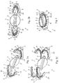
- Figure 1A is an exploded perspective view of a regulating device according to a first embodiment of the invention;
- Figures 1B and 1C are exploded perspective views of the device according to Figure 1A, respectively after mounting of the bearing elements (Figure 1B) and after fitting of the seal (Figure 1C);
- Figures 1D and 1E are views from below and in lateral elevation, respectively, of a device as illustrated in Figures 1A, 1B and 1C after assembly of its various components;
- Figures 1F and 1G are cross-sections along A-A of the device of Figure 1D and along B-B of the device of Figure 1E, respectively;
- Figures 2A and 2B are exploded perspective views, from two different angles, of a regulating device according to a second embodiment of the invention;
- Figure 2C is a view similar to that of Figure 2A, the two portions of the seal being separated from the two portions of the support body;
- Figure 3 is a perspective view of a regulating device in the assembled state (without the control pin) corresponding to those illustrated in Figures 2A, 2B and 2C;
- Figures 4A, 4B and 4C are views from below, in lateral elevation and from above, respectively, of the regulating device of Figure 3;
- Figures 5A and 5B are cross-sections along A-A of the device of Figure 4A and along B-B of the device of Figure 4B, respectively;
- Figures 6A and 6B are cross-sections of an intake manifold integrating three regulating devices as illustrated in Figures 2 to 5, the valves being in the closed position (6A) and the maximum open position (6B), respectively;
- Figure 7 is a partially exploded perspective view of the manifold of Figures 6A and 6B, the regulating devices not being mounted in the body having a planar structure enclosing the chamber of the manifold and integrating the outlets;
- Figures 8 and 9 are exploded perspective views, from two different angles, of regulating devices prior to the mounting thereof in the body having a planar structure forming part of the intake manifold illustrated in Figures 6A, 6B and 7;
- Figure 10 is a perspective view of an intake manifold prior to the mounting of regulating devices as illustrated in Figures 1A to 1G and to the fitting of the seal for providing tightness with the cylinder block;
- Figure 11 is a partial perspective view, from a different angle, of the manifold of Figure 10, the control axis having been introduced into the valve bodies of the regulating devices; and
- Figure 12 is a partial and simplified cross-section along A-A of the manifold illustrated in Figure 6A.
- Figures 1, 2, 3, 4 and 5 show a valve regulating
device 1 intended to regulate the circulation of a fluid in the region of anopening 2. - This
device 1 consists of a pivoting plate-shaped valve body 3, of an annular-shaped support body 4 providing a seat for at least a portion of the peripheral edge of saidvalve body 3 and carrying or integrating twoopposing bearings 5 mounting saidvalve body 3 in a rotational manner, and of acontrol pin 6 determining the position in rotation of saidvalve body 3 and passing through said body by dividing it into two opposing shutter-likeportions 3' and 3". - This
valve body 3 may be displaced in rotation between a totally open position, in which it opposes a minimum visible surface generated by the flow of fluid, and a closed position (preferably substantially at 90° from the open position), in which it rests against the annular seat or seat portion provided by thesupport body 4 and closes the passage 4' through saidannular support body 4, saiddevice 1 being intended to be attached in the region of theopening 2 to be regulated by application of theannular support body 4 against the edge 2' delimiting the circumference of thisopening 2, preferably to be mounted between an outlet and an inlet by providing a passage portion therebetween. - According to the invention, the
support body 4 is provided with aseal 7 with, on the one hand, a first functional segment 7' extending over afirst portion 4" of the internal periphery of theannular support body 4 and bearing against a face of a first 3' of the two shutter-like portions 3', 3" of thevalve body 3 in the closed position and, on the other hand, a secondfunctional segment 7" extending over a second portion 4'" of the internal periphery of theannular support body 4, having a different composition from that of the first functional segment 7' and bearing against the opposing face of the other or second shutter-like portion 3" of thevalve body 3 in the closed position. - Such a dissymmetrical composition of the
seal 7 provides optimal tightness in the closed state of the valve, the degree of tightness increasing in tandem with the closure force, and may be optimised in the normal direction of flow, while at the same time using a simple (substantially planar and flat) valve body. - According to a first highly advantageous characteristic of the invention, the first and second
functional segments 7' and 7" of theseal 7 have protrudinglateral extensions 8, for example in the form of ribs, in the region of the face of thesupport body 4 bearing against the edge 2' of theopening 2, saidextensions 8 being interconnected by intermediate joiningportions 9 also extending in a protruding manner over the bodies 5' of the twoopposing bearings 5, so as to provide a continuous peripheral seal around theopening 2 in the region of which the flow is to be regulated when theregulating device 1 is mounted on said opening. - The form of the edge 2' of the
opening 2 does, of course, match that of the face of thesupport body 4 bearing against it, acompression seal - The
support body 4 and thevalve body 3 are preferably circular in shape, although other shapes are also possible. - These two
bodies shutter portions 3' and 3" (which may have different shapes) of thevalve body 3, like thetubular body 11, may thus have a metal core overmoulded with a thermoplastic material. - According to a preferred embodiment of the invention, the
valve body 3 is mounted on thesupport body 4 so as to be offset toward the face bearing against the edge 2' of theopening 2, the first 3' of the two shutter-like portions 3', 3" of thevalve body 3 pivoting as it moves away from theannular support body 4 when saidvalve body 3 leaves the closed position, while the second shutter-like portion 3" pivots simultaneously within the internal passage 4' of saidsupport body 4. Moreover, the first functional segment 7' is subjected to compressive stress in the closed position of thevalve body 3, between said valve body and thefirst portion 4" of the internal periphery of theannular support body 4 carrying this first functional segment 7' and forming part of the seat, and the secondfunctional segment 7" extends in an overhang arrangement from the second portion 4'" of the internal periphery of theannular support body 4 and is flexurally stressed by thevalve body 3 in the closed position thereof (see Figures 1B, 1C, 1G, 2 and 5B). - Such a separate configuration of the two
functional segments 7' and 7" of the seal provides, in relation to a pivoting valve, tightness optimised for closure in the case of a fluid circulating normally through theannular support body 4 and originating from theopening 2. - The size of the
valve body 3 and that of the passage 4' of theannular support body 4, like the positioning of thevalve body 3 within said passage (decentring relative to a central position), are defined in such a way that the portion (3') of the valve enters into abutment with thefirst portion 4" of the internal periphery of the support body 4 (preferably in the form of a shoulder) in the closed state, while the second shutter-like portion 3" pivots freely and remote from the second portion 4'" of this internal periphery, entering into contact merely with the secondfunctional segment 7". - According to a highly advantageous practical configuration, and as Figures 1 to 5 of the accompanying drawings show, the first and second
functional segments 7' and 7" consist of lip seals and have profiled wing compositions following the contour of theinternal periphery 4", 4'" of theannular support body 4, the first functional segment 7' of theseal 7 consisting of a wing inclined toward the exterior and formed in one piece with abase 10, which rests on thefirst portion 4" of the internal periphery of theannular support body 4 and against which said inclined wing 7' is turned down and enters into surface contact in the compressed state, and the secondfunctional segment 7" consisting of a wing protruding toward the interior as a result of being slightly inclined, thiswing 7" being at least slightly resiliently flexurally stressed under the action of thevalve body 3 when said valve body enters the closed position. - The practical solution thus proposed by the invention is inspired by that disclosed in the aforementioned
French patent application No. 2 856 128 seal 7 are integral with thesupport body 4, rather than with thevalve body 3, thus rendering said valve body simpler to produce and disrupting the flow less in the open position of the valve body. - The
annular support body 4 may comprise first and second internalperipheral portions 4" and 4"' having different radii, and the second internalperipheral portion 4"' may comprise, toward the face opposing the annular support body 4 (opposing the face placed around the opening 2), an inner face inclined toward the interior. - In order to allow fixing of the
pin 6 and to provide guided and wedged holding of the valve body, said valve body comprises a centraltubular formation 11 providing a profile through-passage 11' receiving thecontrol pin 6 with rotational locking, Furthermore, saidvalve body 3 is extended at the two opposing ends of saidtubular formation 11 byhollow fittings 12, 12' forming hubs having a tiered circular outer shape, these fittings cooperating to mount, in a freely rotational manner and with translational locking, thevalve body 3 in theopposing bearings 5 of thesupport body 4, the bodies 5' or thefunctional elements 5" of thebearings 5 having an internal configuration matching the external configuration of the hub-formingfittings 12. 12', and said hubs having through-passages adjacent to the through-passage 11' of the centraltubular formation 11 and also being passed through by thecontrol pin 6. - In order to ensure an effective seal in the region of the
bearings 5 and to provide guided and wedged mounting of the regulatingdevice 1 in the region of theopening 2 to be regulated, it is advantageously provided that the bodies 5' of thebearings 5 protrude on the side of theannular support body 4 that is intended to bear against the edge 2' of theopening 2, and that the intermediate joiningportions 9 are in the form of an arc of a circle and are each extended by a sealinglip 13 bearing against the hub fitting 12, 12' of thevalve body 3 engaged with thebearing 5 in question, so as to form, in cooperation with the twofunctional segments seal 7, a continuous seal between theannular support body 4 and thevalve body 3 in the closed state of said valve body. - So as to optimise the seal in the region of the
bearings 5, in particular relative to the edge 2' of theopening 2, the portion of the bodies 5' of thebearings 5 that protrudes relative to theannular support body 4 is partially indented so that only an end portion of the side of the face of thesupport body 4 that is intended to be placed around the opening 3 of the tiered hub fitting 12, 12' is held and guided in thebearing 5 in question, thesealing lip 13 at least resting on the released portion of saidportion 12" of smaller diameter. - Preferably, and as Figures 1B, 1C, 1E, 1F, 5A, 6A and 6B of the drawings, in particular, show, each of the profiled
sealing lips 13, which are in the form of an arc of a circle and rest on one of the two hollowtiered hub fittings 12, 12', is in section substantially in the shape of a V, one of the wings of which is connected to the corresponding intermediate joiningportion 9, the other wing of which bears at its free end against the shoulder 12'" formed by the projection on the outer face of thefitting 12, 12' in question, and the median ridge of which, formed at the intersection of the two wings, bears against the released portion of theend portion 12" of smaller diameter of thefitting 12, 12' in question. - According to a first variation of the invention emerging from Figure 1 (Figures 1A to 1G), the
annular support body 4 and at least a portion of the bodies 5' of thebearings 5 are formed in one piece. - More precisely, that the one-part piece comprises, on the one hand, the two opposing segments of the
annular body 4 forming the first andsecond portions 4" and 4'" of the internal periphery of said annular body and, on the other hand, the bodies 5' of theopposing bearings 5 enclosing thebearing elements 5", which are formed or attached in these bodies 5'. - As Figures 1A, 1C, 1E and 1F of the accompanying drawings, in particular, show, each bearing 5 may consist of a body 5' forming a casing or structure for receiving a
bearing element 5", the process for mounting said bearing element consisting in wedged interlocking, with rotational locking, of saidelement 5" in said body 5', and each bearingelement 5" may comprise anupper portion 23 integrating arecess 23" for the fitting process, with sliding rotational guiding of thevalve body 3, and a lower portion 23' forming a support base for thebearing element 5" when the regulatingdevice 1 is mounted between the edges of two opposing openings. - According to one characteristic of the invention, it may be provided for each
element 5", that the lower portion 23' forming a support base haslateral extensions 24 defining recess portions for guiding the two portions having different diameters of a tiered hub fitting 12. 12' of thevalve body 3, wherein theseextensions 24 may be interlocked in a mating manner in corresponding cavities in the bearing body 5', which defines the complementary portions of the aforementioned guiding recesses extending concentrically in the extension of therecess 23" in theupper portion 23 of thebearing element 5". - According to an additional advantageous characteristic, the
seal 7, integrating the first and secondfunctional segments 7' and 7", theextensions 8 of said functional segments, the intermediate joiningportions 9 and thesealing lips 13 extending said functional segments, is formed in one piece and is attached by overmoulding to theannular support body 4, in the region of its face that is placed around theopening 2, the outflow of which is to be regulated (see Figures 1A and 1B). - In order to reinforce the connection between the
body 4 and theseal 7, especially if said seal is attached by overmoulding and the constituent materials of the two components are at least partly incompatible, it may be provided that thesupport body 4, and optionally the bearing bodies 5', is/are provided with sites for mechanically coupling or anchoring theseal 7, and optionally the intermediate joiningportions 9, for example in the form of cavities and passages allowing the establishment of bridges made from overmoulded material. - In an optimal manner, the
support body 4 may optionally have a basically hollow, double-wall structure, into which a more pliable material is injected, this material also forming the seal 7 (see Figures 1G, 12). - According to a second variation of the invention emerging from Figures 2 to 5 and 7 to 9 of the accompanying drawings, the
annular support body 4 consists of two identical half-bodies 25 and 25' joined at a plane perpendicular to the plane of saidsupport body 4 and median relative to the twobearings 5. In this case, each half-body 25, 25' integrates abearing 5 extended on each side by asupport body portion 4 so as together to form onehalf 25, 25' of said bearing, and each half-body 25, 25' is provided with a half-seal comprising, in the form of an overmoulded portion, one half of the first functional segment 7', one half of the secondfunctional segment 7, the corresponding halves of thelateral extensions 8 of said functional segments, an intermediate joiningportion 9 connecting said two aforementioned halves, and also asealing lip 13 extending this joiningportion 9. - The two half-
bodies 25 and 25' are preferably assembled by mutual nesting of the free ends of the twosupport body portions 4 provided with matchingincisions 14, 14', the two halves of the first and secondfunctional segments 7' and 7" of theseal 7 entering into adjacent abutment in the assembled state of the two half-bodies 25 and 25', and the assembly optionally being locked by resilient engagement or coupling in the region of theincisions 14, 14' in the joined free ends of the two half-bodies 25 and 25'. - According to a third variation, not shown in the accompanying drawings and incorporating features of the two aforementioned variants, the
annular support body 4 may consist of two identical half-bodies 25 and 25' joined at a plane perpendicular to the plane of saidsupport body 4 and median relative to the twobearings 5, the assembly optionally being produced by connection by mutual nesting of the free ends of said twosupport body portions 4, and theseal 7, integrating the first and secondfunctional segments 7', 7", theextensions 8 of said functional segments, the intermediate joiningportions 9 and the sealinglips 13 extending said functional segments, may be formed in one piece and is attached by overmoulding to theannular support body 4, in the region of its face that is placed around theopening 2, the outflow of which is to be regulated. - In order to limit the degree of wear and damage to the seal and to limit the disruption of the flow of fluid passing through the
regulation device 1 in the open position of thevalve body 3, it may advantageously be provided, as Figures 1G, 5B and 12 of the accompanying drawings show, that theannular support body 4 has a composition, and in particular an internal peripheral form, such that the first and secondfunctional segments 7' and 7" of theseal 7 are set back relative to the contour of the planar projection of the passage 4' in the direction in which the flow passes through said passage, for example by comprising a wall having a greater (at least visible) thickness remote from the edge of saidbody 4 provided with saidsegments 7' and 7". - Alternatively, a thinning of the wall of the
support body 4 may also be provided in the region of the internalperipheral portions 4" and 4"' receiving thefunctional segments 7' and 7". - The protection measure relates primarily to the
functional segment 7" in the form of a wing protruding toward the interior of the passage 4', the functional segment 7' having its end located outside said passage 4' owing to the fact that it extends toward the exterior. - As Figures 1 to 5, 6A and 6B of the drawings show, the
bearings 5 may be provided, on the face opposing the face intended to be placed around theopening 2, the flow of which is to be regulated, with agroove 15 for accommodating a compression seal 15'. Thisgroove 15 may extend through the base 23' (or theextensions 24 thereof) and the body 5' of thebearing 5 forming a housing for thebearing elements 5". - The seal 15' may optionally be extended to form an annular seal encircling the support body in the region of its opposing face, which is not intended to be placed around the
opening 2, the outlet of which is to be regulated. - The present invention also relates, as illustrated in Figures 6A. 6B and 7 of the accompanying drawings, to an intake manifold or
distributor 16 comprising an inlet, achamber 17 and a plurality ofoutlets 18, optionally extended bypipes 19, the flow rate and/or losses in pressure at at least one, preferably a plurality, of saidoutlets 18 being regulated. - This manifold or
distributor 16 is characterised in that eachoutlet 18, the through-flow of which is regulated, comprises on its downstream side aregulating device 1 as described above, thevarious regulating devices 1 that may be present preferably being mutually aligned and passed through by thesame control pin 6. - According to a preferred embodiment, the manifold or
distributor 16 mainly consists of two portions, namely a firsthollow body 20 with a wall delimiting thechamber 17, integrating the inlet and indented in the zone of the outlets, and asecond body 21 having a planar structure with a central plate 21' and aperipheral edge 21", thissecond body 21 enclosing the indented region of thehollow body 20 and integrating theoutlets 18, some of which comprise regulatingdevices 1 attached at theouter openings 2 of said outlets. - As Figures 7 to 9 of the accompanying drawing show, the
outlets 18, the through-flows of which are not regulated, are extended by conduitportions forming pipes 19, theannular support bodies 4 of theregulating devices 1 attached aroundopenings 2 of theregulated outlets 18, in matching mounting sites, having a height or thickness (in the direction of the through-flow) substantially identical to the length of the aforementioned conduitportions forming pipes 19, and preferably substantially identical to the height of theperipheral edge 21 ". - The
regulating devices 1 are then mounted (in a compressed sandwich arrangement) between theopenings 2 of theoutlets 18 and the inlets of the cylinder block (not shown), saiddevices 1 resting in an opposing manner, on the edge regions surrounding these openings, at theirsupport body 4 and the bodies 5' of their bearings 5 (optionally also at the bases 23' of thebearing elements 5"). - Advantageously, the
outlets 18 present in the central plate 21' of thebody 21 having a planar structure open out toward the interior of thechamber 17. Furthermore, thebody 21 having a planar structure has, on the side of the peripheral edge 21' bearing against an opposing edge 21' of thehollow body 21, agroove 22 for receiving a compression seal 22' intended to seal the assembly formed by thehollow body 20 and thebody 21 having a planar structure, and the conduitportions forming pipes 19 have, on their free edges, a groove 19' for receiving acompression seal 19", said edges and the seals 15' fitted in thegrooves 15 of thebearings 5, and optionally surrounding thesupport bodies 4 of theregulating devices 1 on their face opposing that placed around theopenings 2, optionally forming asingle seal 23. - The opening-out toward the
chamber 17 of the entrances of theoutlets 18 allows the flow to be channelled through theopening 2 of these outlets and the turbulence associated with the edge effects to be limited. Furthermore, said opening-out allows the protruding functional joiningsegment 7" to be shielded from the direct action of the flow in the opening position of thevalve body 3 of thedevice 1 in question. - According to a preferred embodiment of the invention emerging, in particular, from Figure 12 of the accompanying drawings, the
outlets 18, the flow of which is regulated by adevice 1, and theannular support bodies 4 of thecorresponding regulating devices 1, which are attached toopenings 2 of saidoutlets 18, cooperate to define aconduit portion 26, in which are disposed thevalve body 3 and thefunctional segments 7' and 7" of theseal 7, said functional segments being laterally set back so as not to be directly exposed to the through-flow of fluid in the open position of thevalve body 3. - The opening-out of the
outlets 18 and a thickening of the wall of theannular bodies 4, remote from their faces placed around theopenings 2, may, for example, advantageously create restrictions in theconduit portion 25, the passage diameter of which is less than that existing in the region of thefunctional segments 7' and 7". Said functional segments are therefore not visible if the passage of saidconduit portion 25 is inspected in the direction of flow of the fluid through said conduit portion. - Finally, the invention also relates to a vehicle having an internal-combustion engine comprising an air intake manifold or distributor mounted on the engine, characterised in that said manifold or distributor is a manifold or
distributor 16 as described above and illustrated in the accompanying drawings. - The invention is not, of course, limited to the embodiments described and illustrated in the accompanying drawings. Modifications are possible, in particular with regard to the constitution of the various elements or by substitution of technical equivalents, without thereby departing from the scope of protection of the invention.
Claims (24)
- Valve regulating device intended to regulate the circulation of a fluid in the region of an opening, said device consisting of a pivoting plate-shaped valve body, of an annular-shaped support body providing a seat for at least a portion of the peripheral edge of said valve body and carrying or integrating two opposing bearings mounting said valve body in a rotational manner, and of a control pin determining the position in rotation of said valve body and passing through said body by dividing it into two opposing shutter-like portions, wherein said valve body may be displaced in rotation between a totally open position, in which it opposes a minimum visible surface generated by the flow of fluid, and a closed position, in which it rests against the annular seat or seat portion provided by the support body and closes the passage through the annular support body, said device being intended to be attached in the region of the opening to be regulated by application of the annular support body against the edge delimiting the circumference of this opening, preferably to be mounted between an outlet and an inlet by providing a passage portion therebetween, device (1) characterised in that the support body (4) is provided with a seal (7) with, on the one hand, a first functional segment (7') extending over a first portion (4") of the internal periphery of the annular support body (4) and bearing against a face of a first (3') of the two shutter-like portions (3', 3") of the valve body (3) in the closed position and, on the other hand, a second functional segment (7") extending over a second portion (4"') of the internal periphery of the annular support body (4), having a different composition from that of the first functional segment (7') and bearing against the opposing face of the other or second shutter-like portion (3") of the valve body (3) in the closed position.
- Regulating device according to claim 1, characterised in that the first and second functional segments (7' and 7") of the seal (7) have protruding lateral extensions (8), for example in the form of ribs, in the region of the face of the support body (4) bearing against the edge (2') of the opening (2), said extensions (8) being interconnected by intermediate joining portions (9) also extending in a protruding manner over the bodies (5') of the two opposing bearings (5), so as to provide a continuous peripheral seal around the opening (2) in the region of which the flow is to be regulated when the regulating device (1) is mounted on said opening.
- Regulating device according to claim 1 or 2, characterised in that the valve body (3) is mounted on the support body (4) so as to be offset toward the face bearing against the edge (2') of the opening (2), the first (3') of the two shutter-like portions (3', 3") of the valve body (3) pivoting as it moves away from the annular support body (4) when said valve body (3) leaves the closed position, while the second shutter-like portion (3") pivots simultaneously within the internal passage (4') of said support body (4), in that the first functional segment (7') is subjected to compressive stress in the closed position of the valve body (3), between said valve body and the first portion (4") of the internal periphery of the annular support body (4) carrying this first functional segment (7') and forming part of the seat, and in that the second functional segment (7") extends in an overhang arrangement from the second portion (4"') of the internal periphery of the annular support body (4) and is flexurally stressed by the valve body (3) in the closed position thereof.
- Regulating device according to claim 3, characterised in that the first and second functional segments (7' and 7") consist of lip seals and have profiled wing compositions following the contour of the internal periphery (4", 4"') of the annular support body (4), the first functional segment (7') of the seal (7) consisting of a wing inclined toward the exterior and formed in one piece with a base (10), which rests on the first portion (4") of the internal periphery of the annular support body (4) and against which said inclined wing (7') is turned down and enters into surface contact in the compressed state, and the second functional segment (7") consisting of a wing protruding toward the interior as a result of being slightly inclined, this wing (7") being at least slightly resiliently flexurally stressed under the action of the valve body (3) when said valve body enters the closed position.
- Regulating device according to any one of claims 1 to 4, characterised in that the valve body (3) comprises a central tubular formation (11) providing a profile through-passage (11') receiving the control pin (6) with rotational locking, and in that said valve body (3) is extended at the two opposing ends of said tubular formation (11) by hollow fittings (12, 12') forming hubs having a tiered circular outer shape, these fittings cooperating to mount, in a freely rotational manner and with translational locking, the valve body (3) in the opposing bearings (5) of the support body (4), the bodies (5') or the functional elements (5") of the bearings (5) having an internal configuration matching the external configuration of the hub-forming fittings (12. 12'), and said hubs having through-passages adjacent to the through-passage (11') of the central tubular formation (11) and also being passed through by the control pin (6).
- Regulating device according to claim 5, characterised in that the bodies (5') of the bearings (5) protrude on the side of the annular support body (4) that is intended to bear against the edge (2') of the opening (2), and in that the intermediate joining portions (9) are in the form of an arc of a circle and are each extended by a sealing lip (13) bearing against the hub fitting (12, 12') of the valve body (3) engaged with the bearing (5) in question, so as to form, in cooperation with the two functional segments (7 and 7") of the seal (7), a continuous seal between the annular support body (4) and the valve body (3) in the closed state of said valve body.
- Regulating device according to claim 6, characterised in that the portion of the bodies (5') of the bearings (5) that protrudes relative to the annular support body (4) is partially indented so that only an end portion of the side of the face of the support body (4) that is intended to be placed around the opening (3) of the tiered hub fitting (12, 12') is held and guided in the bearing (5) in question, the sealing lip (13) at least resting on the released portion of said portion (12") of smaller diameter.
- Regulating device according to claim 7, characterised in that each of the profiled sealing lips (13), which are in the form of an arc of a circle and rest on one of the two hollow tiered hub fittings (12, 12'), is in section substantially in the shape of a V, one of the wings of which is connected to the corresponding intermediate joining portion (9), the other wing of which bears at its free end against the shoulder (12"') formed by the projection on the outer face of the fitting (12, 12') in question, and the median ridge of which, formed at the intersection of the two wings, bears against the released portion of the end portion (12") of smaller diameter of the fitting (12, 12') in question.
- Regulating device according to any one of claims 1 to 8, characterised in that the annular support body (4) and at least a portion of the bodies (5') of the bearings (5) are formed in one piece.
- Regulating device according to claim 9, characterised in that the one-part piece comprises, on the one hand, the two opposing segments of the annular body (4) forming the first and second portions (4" and 4"') of the internal periphery of said annular body and, on the other hand, the bodies (5') of the opposing bearings (5) enclosing the bearing elements (5"), which are formed or attached in these bodies (5').
- Regulating device according to claim 10, characterised in that each bearing (5) consists of a body (5') forming a casing or structure for receiving a bearing element (5"), the process for mounting said bearing element consisting in wedged interlocking, with rotational locking, of said element (5") in said body (5'), and in that each bearing element (5") comprises an upper portion (23) integrating a recess (23") for the fitting process, with sliding rotational guiding of the valve body (3), and a lower portion (23') forming a support base for the bearing element (5") when the regulating device (1) is mounted between the edges of two opposing openings.
- Regulating device according to claim 11, when appended to any one of claims 5 to 8, characterised in that the lower portion (23') forming a support base has lateral extensions (24) defining recess portions for guiding the two portions having different diameters of a tiered hub fitting (12. 12') of the valve body (3), wherein these extensions (24) may be interlocked in a mating manner in corresponding cavities in the bearing body (5'), which defines the complementary portions of the aforementioned guiding recesses extending concentrically in the extension of the recess (23") in the upper portion (23) of the bearing element (5").
- Regulating device according to any one of claims 1 to 12, characterised in that the seal (7), integrating the first and second functional segments (7' and 7"), the extensions (8) of said functional segments, the intermediate joining portions (9) and the sealing lips (13) extending said functional segments, is formed in one piece and is attached by overmoulding to the annular support body (4), in the region of its face that is placed around the opening (2), the outflow of which is to be regulated.
- Regulating device according to any one of claims 1 to 13, characterised in that the support body (4), and optionally the bearing bodies (5'), is/are provided with sites for mechanically coupling or anchoring the seal (7), and optionally the intermediate joining portions (9), for example in the form of cavities and passages allowing the establishment of bridges made from overmoulded material.
- Regulating device according to any one of claims 1 to 14, characterised in that the annular support body (4) consists of two identical half-bodies (25 and 25') joined at a plane perpendicular to the plane of said support body (4) and median relative to the two bearings (5), in that each half-body integrates a bearing (5) extended on each side by a support body portion (4) so as together to form one half (25, 25') of said bearing, and in that each half-body (25, 25') is provided with a half-seal comprising, in the form of an overmoulded portion, one half of the first functional segment (7'), one half of the second functional segment (7), the corresponding halves of the lateral extensions (8) of said functional segments, an intermediate joining portion (9) connecting said two aforementioned halves, and also a sealing lip (13) extending this joining portion (9).
- Regulating device according to claim 15, characterised in that the two half-bodies (25 and 25') are assembled by mutual nesting of the free ends of the two support body portions (4) provided with matching incisions (14, 14'), the two halves of the first and second functional segments (7' and 7") of the seal (7) entering into adjacent abutment in the assembled state of the two half-bodies (25 and 25'), and the assembly optionally being locked by resilient engagement or coupling in the region of the incisions (14, 14') in the joined free ends of the two half-bodies (25 and 25').
- Regulating device according to claim 13 or 14, when appended to any one of claims 2 to 8, characterised in that the annular support body (4) consists of two identical half-bodies (25 and 25') joined at a plane perpendicular to the plane of said support body (4) and median relative to the two bearings (5), the assembly optionally being produced by connection by mutual nesting of the free ends of said two support body portions (4), and in that the seal (7), integrating the first and second functional segments (7', 7"), the extensions (8) of said functional segments, the intermediate joining portions (9) and the sealing lips (13) extending said functional segments, is formed in one piece and is attached by overmoulding to the annular support body (4), in the region of its face that is placed around the opening (2), the outflow of which is to be regulated.
- Regulating device according to any one of claims 1 to 17, characterised in that the annular support body (4) has a composition, and in particular an internal peripheral form, such that the first and second functional segments (7' and 7") of the seal (7) are set back relative to the contour of the planar projection of the passage (4') in the direction in which the flow passes through said passage, for example by comprising a wall having a greater at least visible thickness remote from the edge of said body (4) provided with said segments (7') and (7"), the bearings (5) optionally being provided, on the face opposing the face intended to be placed around the opening (2), the flow of which is to be regulated, with a groove (15) for accommodating a compression seal (15').
- Intake manifold or distributor comprising an inlet, a chamber and a plurality of outlets, optionally extended by pipes, the flow rate and/or losses in pressure at at least one, preferably a plurality, of said outlets being regulated, manifold or distributor characterised in that each outlet (18), the through-flow of which is regulated, comprises on its downstream side a regulating device (1) according to any one of claims 1 to 18, the various regulating devices (1) that may be present preferably being mutually aligned and passed through by the same control pin (6).
- Manifold or distributor according to claim 19, characterised in that it mainly consists of two portions, namely a first hollow body (20) with a wall delimiting the chamber (17), integrating the inlet and indented in the zone of the outlets, and a second body (21) having a planar structure with a central plate (21') and a peripheral edge (21"), this second body (21) enclosing the indented region of the hollow body (20) and integrating the outlets (18), some of which comprise regulating devices (1) attached at the outer openings (2) of said outlets.
- Manifold or distributor according to claim 20, characterised in that the outlets (18), the through-flows of which are not regulated, are extended by conduit portions forming pipes (19), the annular support bodies (4) of the regulating devices (1) attached around openings (2) of the regulated outlets (18), in matching mounting sites, having a height or thickness substantially identical to the length of the aforementioned conduit portions forming pipes (19), and preferably substantially identical to the height of the peripheral edge (21").
- Manifold or distributor according to claim 20 or 21, characterised in that the outlets (18) present in the central plate (21') of the body (21) having a planar structure open out toward the interior of the chamber (17), in that the body (21) having a planar structure has, on the side of the peripheral edge (21') bearing against an opposing edge (21') of the hollow body (21), a groove (22) for receiving a compression seal (22') intended to seal the assembly formed by the hollow body (20) and the body (21) having a planar structure, and in that the conduit portions forming pipes (19) have, on their free edges, a groove (19') for receiving a compression seal (19"), said edges and the seals (15') fitted in the grooves (15) of the bearings (5), and optionally surrounding the support bodies (4) of the regulating devices (1) on their face opposing that placed around the openings (2), optionally forming a single seal (23).
- Manifold or distributor according to any one of claims 19 to 22, characterised in that the outlets (18), the flow of which is regulated by a device (1), and the annular support bodies (4) of the corresponding regulating devices (1), which are attached to openings (2) of said outlets (18), cooperate to define a conduit portion (26), in which are disposed the valve body (3) and the functional segments (7' and 7") of the seal (7), said functional segments being laterally set back so as not to be directly exposed to the through-flow of fluid in the open position of the valve body (3).
- Vehicle having an internal-combustion engine comprising an air intake manifold or distributor mounted on the engine, characterised in that said manifold or distributor is a manifold or distributor (16) according to any one of claims 19 to 23.
Applications Claiming Priority (1)
| Application Number | Priority Date | Filing Date | Title |
|---|---|---|---|
| FR0510287A FR2891886B1 (en) | 2005-10-07 | 2005-10-07 | CLAMP CONTROL DEVICE AND ADMISSION MANIFOLD COMPRISING AT LEAST ONE SUCH DEVICE |
Publications (4)
| Publication Number | Publication Date |
|---|---|
| EP1772615A2 true EP1772615A2 (en) | 2007-04-11 |
| EP1772615A3 EP1772615A3 (en) | 2007-04-25 |
| EP1772615B1 EP1772615B1 (en) | 2010-03-31 |
| EP1772615B8 EP1772615B8 (en) | 2010-05-19 |
Family
ID=36617203
Family Applications (1)
| Application Number | Title | Priority Date | Filing Date |
|---|---|---|---|
| EP06121922A Active EP1772615B8 (en) | 2005-10-07 | 2006-10-06 | Valve regulating device and intake manifold comprising at least one such device |
Country Status (5)
| Country | Link |
|---|---|
| US (1) | US7353801B2 (en) |
| EP (1) | EP1772615B8 (en) |
| AT (1) | ATE462883T1 (en) |
| DE (1) | DE602006013246D1 (en) |
| FR (1) | FR2891886B1 (en) |
Cited By (9)
| Publication number | Priority date | Publication date | Assignee | Title |
|---|---|---|---|---|
| WO2013079428A1 (en) * | 2011-11-28 | 2013-06-06 | Mahle International Gmbh | Fresh air supply device |
| DE102012203232A1 (en) * | 2012-03-01 | 2013-09-05 | Mahle International Gmbh | Internal combustion engine with fresh gas distributor |
| WO2019242833A1 (en) * | 2018-06-18 | 2019-12-26 | Pierburg Gmbh | Flap device for an internal combustion engine |
| USD900162S1 (en) * | 2019-05-19 | 2020-10-27 | Deepmotor, Inc. | Intake manifold |
| WO2021037356A1 (en) * | 2019-08-28 | 2021-03-04 | Pierburg Gmbh | Throttle valve device for an exhaust gas tract or an air intake tract of an internal combustion engine and a method for producing a throttle valve housing of a throttle valve device |
| USD957466S1 (en) | 2020-11-10 | 2022-07-12 | Deepmotor Inc | Intake manifold |
| USD957463S1 (en) | 2020-09-30 | 2022-07-12 | Deepmotor Inc | Intake manifold |
| USD962291S1 (en) | 2021-08-06 | 2022-08-30 | Deepmotor Inc | Intake manifold |
| USD962995S1 (en) | 2020-08-31 | 2022-09-06 | Deepmotor Inc | Intake manifold |
Families Citing this family (24)
| Publication number | Priority date | Publication date | Assignee | Title |
|---|---|---|---|---|
| US20100193594A1 (en) * | 2004-12-20 | 2010-08-05 | Edc Automotive, Llc | Electronic thermostat |
| JP2008045430A (en) * | 2006-08-11 | 2008-02-28 | Denso Corp | Multiple integral valve opening-closing device |
| DE102006043342A1 (en) * | 2006-09-15 | 2008-03-27 | Siemens Ag | Method for producing flap mechanisms in air distribution pipes of internal combustion engines |
| US20080314352A1 (en) * | 2007-06-20 | 2008-12-25 | Brosseau Michael R | Edge-pivot charge-motion control valve system for an internal combustion engine manifold runner |
| US20090001308A1 (en) * | 2007-06-26 | 2009-01-01 | Dalo Dominic N | Valve to shaft assembly |
| FR2927124B1 (en) * | 2008-02-05 | 2013-02-22 | Mark Iv Systemes Moteurs Sa | PROCESS FOR PRODUCING A SUPPORT PLATE FOR CHAMPS OF FLAP AND SUPPORT PLATE |
| US8028677B2 (en) * | 2008-09-09 | 2011-10-04 | Mark Iv Systemes Moteurs Usa, Inc. | Assembly and method for controlling an air intake runner |
| US7690366B1 (en) * | 2009-05-18 | 2010-04-06 | Robert Bosch Gmbh | Throttle valve and method of producing the same |
| US7955542B2 (en) * | 2009-05-18 | 2011-06-07 | Robert Bosch Gmbh | Method of producing a throttle assembly |
| FR2952408B1 (en) * | 2009-11-12 | 2011-12-30 | Mark Iv Systemes Moteurs Sa | PROCESS FOR MANUFACTURING AN INTAKE MANIFOLD AND CORRESPONDING MANIFOLD |
| DE102009054184A1 (en) * | 2009-11-23 | 2011-05-26 | Mahle International Gmbh | Damper device and suction system |
| JP2011220143A (en) * | 2010-04-06 | 2011-11-04 | Denso Corp | Air-intake apparatus of internal combustion engine |
| JP2012092966A (en) * | 2010-10-01 | 2012-05-17 | Canon Anelva Corp | Flow path opening/closing apparatus |
| EP2557298B1 (en) * | 2011-08-12 | 2017-11-22 | Röchling Automotive SE & Co. KG | Flap device with at least two separately produced flaps fitted together for joint motion |
| GB201203559D0 (en) * | 2012-02-29 | 2012-04-11 | Chargepoint Technology Ltd | Improvements relating to valves |
| DE102013006196B4 (en) * | 2013-04-11 | 2016-07-07 | Mann + Hummel Gmbh | Suction pipe for gas of an internal combustion engine with a flap unit |
| JP5858013B2 (en) * | 2013-08-08 | 2016-02-10 | 株式会社デンソー | Intake system |
| JP6252026B2 (en) * | 2013-08-08 | 2017-12-27 | アイシン精機株式会社 | Intake device and intake control valve |
| US9976666B1 (en) * | 2016-02-10 | 2018-05-22 | Bobby New | Butterfly valve assembly |
| US20190125260A1 (en) * | 2016-04-12 | 2019-05-02 | Icentia Inc. | Method of joining elastomeric lips,press-switch system, and wearable monitor |
| CN107448622A (en) * | 2017-09-29 | 2017-12-08 | 杰锋汽车动力系统股份有限公司 | A kind of high-temperature pipe valve |
| GB2568337A (en) * | 2017-11-09 | 2019-05-15 | Eaton Intelligent Power Ltd | Check Valve |
| DK180481B1 (en) * | 2019-10-11 | 2021-05-20 | Agrisys As | Valve device with seals mounted in grooves in the valve device housing |
| GB2610406A (en) | 2021-09-02 | 2023-03-08 | Black & Decker Inc | Seal |
Citations (3)
| Publication number | Priority date | Publication date | Assignee | Title |
|---|---|---|---|---|
| EP0968360A1 (en) | 1997-03-20 | 2000-01-05 | FILTERWERK MANN + HUMMEL GmbH | Intake module |
| FR2805878A1 (en) | 2000-03-01 | 2001-09-07 | Mark Iv Systemes Moteurs Sa | VALVE VALVE DEVICE AND REGULATION ASSEMBLY COMPRISING SUCH DEVICES |
| FR2856128A1 (en) | 2003-06-10 | 2004-12-17 | Mark Iv Systemes Moteurs Sa | VALVE DEVICE AND MULTI-CHANNEL REGULATION ASSEMBLY COMPRISING SEVERAL SUCH DEVICES |
Family Cites Families (21)
| Publication number | Priority date | Publication date | Assignee | Title |
|---|---|---|---|---|
| DE2427995A1 (en) * | 1974-06-10 | 1976-01-02 | Standard Elektrik Lorenz Ag | Butterfly-type gas valve - has housing in two identical halves with widened cylindrical portions accommodating butterfly |
| US3910552A (en) * | 1974-11-18 | 1975-10-07 | Worcester Controls Corp | Adjustable wafer butterfly valve |
| GB2249611A (en) * | 1990-11-06 | 1992-05-13 | Ford Motor Co | Throttle body sealing unit |
| US5236003A (en) * | 1993-01-19 | 1993-08-17 | Helmut Habicht | Modular butterfly valve |
| SE9402882D0 (en) * | 1994-08-31 | 1994-08-31 | Volvo Ab | Butterfly valve assembly |
| DE19510528A1 (en) * | 1995-03-23 | 1996-09-26 | Bosch Gmbh Robert | Adjustment device |
| US5620167A (en) * | 1996-02-22 | 1997-04-15 | Habicht; Helmut | Modular butterfly valve for tablets, capsules and the like |
| US5715782A (en) * | 1996-08-29 | 1998-02-10 | Genral Motors Corporation | Composite molded butterfly valve for an internal combustion engine |
| US5979872A (en) * | 1997-05-19 | 1999-11-09 | Gds Manufacturing Co. | Retrofittable corrosion-resistant volume damper |
| AT2743U1 (en) * | 1998-05-07 | 1999-03-25 | Avl List Gmbh | INLET PIPE ARRANGEMENT FOR AN INTERNAL COMBUSTION ENGINE |
| DE19918777A1 (en) | 1999-04-24 | 2000-10-26 | Mann & Hummel Filter | Flap valve arrangement as throttles in intake channels in IC engines has power transmission shaft connecting flap valve wings, and injection-molded valve modules |
| HUP0202827A2 (en) | 1999-08-24 | 2002-12-28 | Siemens Ag | Suction intake device for an internal combustion machine |
| FR2797931B1 (en) * | 1999-08-31 | 2001-10-05 | Mark Iv Systemes Moteurs Sa | DEVICE FOR CONTROLLING THE FLOW IN A DUCT PORTION OR A PASSAGE AND MANIFOLD COMPRISING SUCH A DEVICE |
| US6354267B1 (en) * | 2000-03-28 | 2002-03-12 | Borgwarner Inc. | Injection molded throttle body |
| IL136370A0 (en) * | 2000-05-25 | 2001-06-14 | Twitoplast Ltd | Split damper housing |
| FR2816006B1 (en) * | 2000-10-27 | 2003-05-02 | Solvay | DEVICE FOR SEALING AIR INTAKE DUCTS OF AN ENGINE |
| FR2819557B1 (en) * | 2001-01-17 | 2003-09-19 | Mark Iv Systemes Moteurs Sa | INTAKE MANIFOLD OR DISTRIBUTOR FOR A HEAT ENGINE AND MANUFACTURING METHOD |
| EP1380741B1 (en) * | 2002-07-11 | 2012-05-30 | Volvo Car Corporation | Throttle device |
| US6763802B1 (en) * | 2002-11-25 | 2004-07-20 | Hayes Lemmerz International, Inc. | Intake manifold valve system |
| US7090193B2 (en) * | 2003-03-28 | 2006-08-15 | Tomoe Technical Research Company Ltd. | Butterfly valve |
| DE202004020030U1 (en) * | 2004-12-22 | 2005-03-10 | Mann + Hummel Gmbh | Suction facility for a multi-cylinder internal combustion engine feeds combustion air to each cylinder while controlling it with adjustable twisting flaps |
-
2005
- 2005-10-07 FR FR0510287A patent/FR2891886B1/en not_active Expired - Fee Related
-
2006
- 2006-10-06 AT AT06121922T patent/ATE462883T1/en not_active IP Right Cessation
- 2006-10-06 EP EP06121922A patent/EP1772615B8/en active Active
- 2006-10-06 US US11/543,984 patent/US7353801B2/en active Active
- 2006-10-06 DE DE602006013246T patent/DE602006013246D1/en active Active
Patent Citations (3)
| Publication number | Priority date | Publication date | Assignee | Title |
|---|---|---|---|---|
| EP0968360A1 (en) | 1997-03-20 | 2000-01-05 | FILTERWERK MANN + HUMMEL GmbH | Intake module |
| FR2805878A1 (en) | 2000-03-01 | 2001-09-07 | Mark Iv Systemes Moteurs Sa | VALVE VALVE DEVICE AND REGULATION ASSEMBLY COMPRISING SUCH DEVICES |
| FR2856128A1 (en) | 2003-06-10 | 2004-12-17 | Mark Iv Systemes Moteurs Sa | VALVE DEVICE AND MULTI-CHANNEL REGULATION ASSEMBLY COMPRISING SEVERAL SUCH DEVICES |
Cited By (13)
| Publication number | Priority date | Publication date | Assignee | Title |
|---|---|---|---|---|
| WO2013079428A1 (en) * | 2011-11-28 | 2013-06-06 | Mahle International Gmbh | Fresh air supply device |
| CN103987943A (en) * | 2011-11-28 | 2014-08-13 | 马勒国际有限公司 | Fresh air supply device |
| CN103987943B (en) * | 2011-11-28 | 2016-08-24 | 马勒国际有限公司 | Fresh air unit |
| DE102012203232A1 (en) * | 2012-03-01 | 2013-09-05 | Mahle International Gmbh | Internal combustion engine with fresh gas distributor |
| US9261014B2 (en) | 2012-03-01 | 2016-02-16 | Mahle International Gmbh | Internal combustion engine with fresh gas distributor |
| EP2820283B1 (en) * | 2012-03-01 | 2019-04-10 | Mahle International GmbH | Engine with fresh air distributor |
| WO2019242833A1 (en) * | 2018-06-18 | 2019-12-26 | Pierburg Gmbh | Flap device for an internal combustion engine |
| USD900162S1 (en) * | 2019-05-19 | 2020-10-27 | Deepmotor, Inc. | Intake manifold |
| WO2021037356A1 (en) * | 2019-08-28 | 2021-03-04 | Pierburg Gmbh | Throttle valve device for an exhaust gas tract or an air intake tract of an internal combustion engine and a method for producing a throttle valve housing of a throttle valve device |
| USD962995S1 (en) | 2020-08-31 | 2022-09-06 | Deepmotor Inc | Intake manifold |
| USD957463S1 (en) | 2020-09-30 | 2022-07-12 | Deepmotor Inc | Intake manifold |
| USD957466S1 (en) | 2020-11-10 | 2022-07-12 | Deepmotor Inc | Intake manifold |
| USD962291S1 (en) | 2021-08-06 | 2022-08-30 | Deepmotor Inc | Intake manifold |
Also Published As
| Publication number | Publication date |
|---|---|
| US20070084437A1 (en) | 2007-04-19 |
| EP1772615B1 (en) | 2010-03-31 |
| FR2891886B1 (en) | 2010-04-02 |
| DE602006013246D1 (en) | 2010-05-12 |
| ATE462883T1 (en) | 2010-04-15 |
| FR2891886A1 (en) | 2007-04-13 |
| US7353801B2 (en) | 2008-04-08 |
| EP1772615A3 (en) | 2007-04-25 |
| EP1772615B8 (en) | 2010-05-19 |
Similar Documents
| Publication | Publication Date | Title |
|---|---|---|
| US7353801B2 (en) | Valve regulating device and intake manifold comprising at least one such device | |
| CA1050854A (en) | Water faucet | |
| US6494466B1 (en) | Valve seal construction with non-congruent side serrations | |
| JP2014114715A (en) | Exhaust gas recirculation valve | |
| CA3004395C (en) | Air intake device for internal combustion engine | |
| US20200103038A1 (en) | Ball Valve with Improved Assembly Configuration | |
| KR102013965B1 (en) | Single-lever mixing cartridge | |
| US6536475B2 (en) | Fluid selector valve | |
| CA2338441C (en) | Ball valve | |
| KR102013000B1 (en) | Single-lever mixing cartridge | |
| CN215977521U (en) | Shower inner core and shower | |
| EP1138895A2 (en) | Rotary-body type throttle for spark ignition internal combustion engine | |
| US11137094B2 (en) | Clip end device | |
| CN106907278B (en) | Charge motion control valve seal and method of assembling same | |
| US6681804B2 (en) | Device for controlling the output of rotary compressors | |
| FR2905159A1 (en) | Valve controlling device for vehicle`s internal combustion engine, has annular support body with functional segments of bushing, which are situated with respect to contour of projection plane of passage in fluid flow direction | |
| JP3679745B2 (en) | Gas cock ball switching valve | |
| JP2012524229A (en) | Throttle valve and manufacturing method | |
| CN112128407B (en) | Fluid management assembly | |
| US20230235827A1 (en) | Reed valve | |
| US11536376B2 (en) | Gate valve | |
| AU742512B2 (en) | Ball valve | |
| KR100211292B1 (en) | Stop valve for hot water supply device | |
| KR100220314B1 (en) | Stop valve using hot water device | |
| CN106917882A (en) | Tap with eccentrically arranged valve |
Legal Events
| Date | Code | Title | Description |
|---|---|---|---|
| PUAI | Public reference made under article 153(3) epc to a published international application that has entered the european phase |
Free format text: ORIGINAL CODE: 0009012 |
|
| PUAL | Search report despatched |
Free format text: ORIGINAL CODE: 0009013 |
|
| AK | Designated contracting states |
Kind code of ref document: A2 Designated state(s): AT BE BG CH CY CZ DE DK EE ES FI FR GB GR HU IE IS IT LI LT LU LV MC NL PL PT RO SE SI SK TR |
|
| AX | Request for extension of the european patent |
Extension state: AL BA HR MK YU |
|
| AK | Designated contracting states |
Kind code of ref document: A3 Designated state(s): AT BE BG CH CY CZ DE DK EE ES FI FR GB GR HU IE IS IT LI LT LU LV MC NL PL PT RO SE SI SK TR |
|
| AX | Request for extension of the european patent |
Extension state: AL BA HR MK YU |
|
| 17P | Request for examination filed |
Effective date: 20071024 |
|
| 17Q | First examination report despatched |
Effective date: 20071123 |
|
| AKX | Designation fees paid |
Designated state(s): AT BE BG CH CY CZ DE DK EE ES FI FR GB GR HU IE IS IT LI LT LU LV MC NL PL PT RO SE SI SK TR |
|
| RIN1 | Information on inventor provided before grant (corrected) |
Inventor name: WINKELMULLER, HUGUES Inventor name: ROHMER, PHILIPPE Inventor name: BLOCK, STEVE |
|
| GRAP | Despatch of communication of intention to grant a patent |
Free format text: ORIGINAL CODE: EPIDOSNIGR1 |
|
| GRAS | Grant fee paid |
Free format text: ORIGINAL CODE: EPIDOSNIGR3 |
|
| GRAA | (expected) grant |
Free format text: ORIGINAL CODE: 0009210 |
|
| AK | Designated contracting states |
Kind code of ref document: B1 Designated state(s): AT BE BG CH CY CZ DE DK EE ES FI FR GB GR HU IE IS IT LI LT LU LV MC NL PL PT RO SE SI SK TR |
|
| REG | Reference to a national code |
Ref country code: GB Ref legal event code: FG4D Ref country code: CH Ref legal event code: EP |
|
| RAP2 | Party data changed (patent owner data changed or rights of a patent transferred) |
Owner name: MARK IV SYSTEMES MOTEURS (SAS) |
|
| REG | Reference to a national code |
Ref country code: IE Ref legal event code: FG4D |
|
| REF | Corresponds to: |
Ref document number: 602006013246 Country of ref document: DE Date of ref document: 20100512 Kind code of ref document: P |
|
| REG | Reference to a national code |
Ref country code: NL Ref legal event code: VDEP Effective date: 20100331 |
|
| PG25 | Lapsed in a contracting state [announced via postgrant information from national office to epo] |
Ref country code: LT Free format text: LAPSE BECAUSE OF FAILURE TO SUBMIT A TRANSLATION OF THE DESCRIPTION OR TO PAY THE FEE WITHIN THE PRESCRIBED TIME-LIMIT Effective date: 20100331 |
|
| LTIE | Lt: invalidation of european patent or patent extension |
Effective date: 20100331 |
|
| PG25 | Lapsed in a contracting state [announced via postgrant information from national office to epo] |
Ref country code: PL Free format text: LAPSE BECAUSE OF FAILURE TO SUBMIT A TRANSLATION OF THE DESCRIPTION OR TO PAY THE FEE WITHIN THE PRESCRIBED TIME-LIMIT Effective date: 20100331 Ref country code: FI Free format text: LAPSE BECAUSE OF FAILURE TO SUBMIT A TRANSLATION OF THE DESCRIPTION OR TO PAY THE FEE WITHIN THE PRESCRIBED TIME-LIMIT Effective date: 20100331 Ref country code: LV Free format text: LAPSE BECAUSE OF FAILURE TO SUBMIT A TRANSLATION OF THE DESCRIPTION OR TO PAY THE FEE WITHIN THE PRESCRIBED TIME-LIMIT Effective date: 20100331 Ref country code: SI Free format text: LAPSE BECAUSE OF FAILURE TO SUBMIT A TRANSLATION OF THE DESCRIPTION OR TO PAY THE FEE WITHIN THE PRESCRIBED TIME-LIMIT Effective date: 20100331 Ref country code: AT Free format text: LAPSE BECAUSE OF FAILURE TO SUBMIT A TRANSLATION OF THE DESCRIPTION OR TO PAY THE FEE WITHIN THE PRESCRIBED TIME-LIMIT Effective date: 20100331 |
|
| PG25 | Lapsed in a contracting state [announced via postgrant information from national office to epo] |
Ref country code: ES Free format text: LAPSE BECAUSE OF FAILURE TO SUBMIT A TRANSLATION OF THE DESCRIPTION OR TO PAY THE FEE WITHIN THE PRESCRIBED TIME-LIMIT Effective date: 20100712 Ref country code: EE Free format text: LAPSE BECAUSE OF FAILURE TO SUBMIT A TRANSLATION OF THE DESCRIPTION OR TO PAY THE FEE WITHIN THE PRESCRIBED TIME-LIMIT Effective date: 20100331 Ref country code: CY Free format text: LAPSE BECAUSE OF FAILURE TO SUBMIT A TRANSLATION OF THE DESCRIPTION OR TO PAY THE FEE WITHIN THE PRESCRIBED TIME-LIMIT Effective date: 20100331 Ref country code: BE Free format text: LAPSE BECAUSE OF FAILURE TO SUBMIT A TRANSLATION OF THE DESCRIPTION OR TO PAY THE FEE WITHIN THE PRESCRIBED TIME-LIMIT Effective date: 20100331 Ref country code: SE Free format text: LAPSE BECAUSE OF FAILURE TO SUBMIT A TRANSLATION OF THE DESCRIPTION OR TO PAY THE FEE WITHIN THE PRESCRIBED TIME-LIMIT Effective date: 20100331 Ref country code: RO Free format text: LAPSE BECAUSE OF FAILURE TO SUBMIT A TRANSLATION OF THE DESCRIPTION OR TO PAY THE FEE WITHIN THE PRESCRIBED TIME-LIMIT Effective date: 20100331 Ref country code: NL Free format text: LAPSE BECAUSE OF FAILURE TO SUBMIT A TRANSLATION OF THE DESCRIPTION OR TO PAY THE FEE WITHIN THE PRESCRIBED TIME-LIMIT Effective date: 20100331 |
|
| PG25 | Lapsed in a contracting state [announced via postgrant information from national office to epo] |
Ref country code: SK Free format text: LAPSE BECAUSE OF FAILURE TO SUBMIT A TRANSLATION OF THE DESCRIPTION OR TO PAY THE FEE WITHIN THE PRESCRIBED TIME-LIMIT Effective date: 20100331 Ref country code: CZ Free format text: LAPSE BECAUSE OF FAILURE TO SUBMIT A TRANSLATION OF THE DESCRIPTION OR TO PAY THE FEE WITHIN THE PRESCRIBED TIME-LIMIT Effective date: 20100331 Ref country code: IS Free format text: LAPSE BECAUSE OF FAILURE TO SUBMIT A TRANSLATION OF THE DESCRIPTION OR TO PAY THE FEE WITHIN THE PRESCRIBED TIME-LIMIT Effective date: 20100731 |
|
| PG25 | Lapsed in a contracting state [announced via postgrant information from national office to epo] |
Ref country code: DK Free format text: LAPSE BECAUSE OF FAILURE TO SUBMIT A TRANSLATION OF THE DESCRIPTION OR TO PAY THE FEE WITHIN THE PRESCRIBED TIME-LIMIT Effective date: 20100331 Ref country code: PT Free format text: LAPSE BECAUSE OF FAILURE TO SUBMIT A TRANSLATION OF THE DESCRIPTION OR TO PAY THE FEE WITHIN THE PRESCRIBED TIME-LIMIT Effective date: 20100802 |
|
| PLBE | No opposition filed within time limit |
Free format text: ORIGINAL CODE: 0009261 |
|
| STAA | Information on the status of an ep patent application or granted ep patent |
Free format text: STATUS: NO OPPOSITION FILED WITHIN TIME LIMIT |
|
| 26N | No opposition filed |
Effective date: 20110104 |
|
| PG25 | Lapsed in a contracting state [announced via postgrant information from national office to epo] |
Ref country code: IT Free format text: LAPSE BECAUSE OF FAILURE TO SUBMIT A TRANSLATION OF THE DESCRIPTION OR TO PAY THE FEE WITHIN THE PRESCRIBED TIME-LIMIT Effective date: 20100331 |
|
| PG25 | Lapsed in a contracting state [announced via postgrant information from national office to epo] |
Ref country code: MC Free format text: LAPSE BECAUSE OF NON-PAYMENT OF DUE FEES Effective date: 20101031 |
|
| REG | Reference to a national code |
Ref country code: CH Ref legal event code: PL |
|
| GBPC | Gb: european patent ceased through non-payment of renewal fee |
Effective date: 20101006 |
|
| PG25 | Lapsed in a contracting state [announced via postgrant information from national office to epo] |
Ref country code: LI Free format text: LAPSE BECAUSE OF NON-PAYMENT OF DUE FEES Effective date: 20101031 Ref country code: CH Free format text: LAPSE BECAUSE OF NON-PAYMENT OF DUE FEES Effective date: 20101031 |
|
| PG25 | Lapsed in a contracting state [announced via postgrant information from national office to epo] |
Ref country code: GB Free format text: LAPSE BECAUSE OF NON-PAYMENT OF DUE FEES Effective date: 20101006 |
|
| PG25 | Lapsed in a contracting state [announced via postgrant information from national office to epo] |
Ref country code: IE Free format text: LAPSE BECAUSE OF NON-PAYMENT OF DUE FEES Effective date: 20101006 |
|
| PG25 | Lapsed in a contracting state [announced via postgrant information from national office to epo] |
Ref country code: BG Free format text: LAPSE BECAUSE OF FAILURE TO SUBMIT A TRANSLATION OF THE DESCRIPTION OR TO PAY THE FEE WITHIN THE PRESCRIBED TIME-LIMIT Effective date: 20100331 Ref country code: LU Free format text: LAPSE BECAUSE OF NON-PAYMENT OF DUE FEES Effective date: 20101006 Ref country code: HU Free format text: LAPSE BECAUSE OF FAILURE TO SUBMIT A TRANSLATION OF THE DESCRIPTION OR TO PAY THE FEE WITHIN THE PRESCRIBED TIME-LIMIT Effective date: 20101001 |
|
| PG25 | Lapsed in a contracting state [announced via postgrant information from national office to epo] |
Ref country code: TR Free format text: LAPSE BECAUSE OF FAILURE TO SUBMIT A TRANSLATION OF THE DESCRIPTION OR TO PAY THE FEE WITHIN THE PRESCRIBED TIME-LIMIT Effective date: 20100331 |
|
| PGFP | Annual fee paid to national office [announced via postgrant information from national office to epo] |
Ref country code: FR Payment date: 20120918 Year of fee payment: 7 |
|
| PG25 | Lapsed in a contracting state [announced via postgrant information from national office to epo] |
Ref country code: BG Free format text: LAPSE BECAUSE OF FAILURE TO SUBMIT A TRANSLATION OF THE DESCRIPTION OR TO PAY THE FEE WITHIN THE PRESCRIBED TIME-LIMIT Effective date: 20100630 |
|
| REG | Reference to a national code |
Ref country code: FR Ref legal event code: ST Effective date: 20140630 |
|
| PG25 | Lapsed in a contracting state [announced via postgrant information from national office to epo] |
Ref country code: GR Free format text: LAPSE BECAUSE OF FAILURE TO SUBMIT A TRANSLATION OF THE DESCRIPTION OR TO PAY THE FEE WITHIN THE PRESCRIBED TIME-LIMIT Effective date: 20100331 Ref country code: FR Free format text: LAPSE BECAUSE OF NON-PAYMENT OF DUE FEES Effective date: 20131031 |
|
| PGFP | Annual fee paid to national office [announced via postgrant information from national office to epo] |
Ref country code: DE Payment date: 20230920 Year of fee payment: 18 |