EP1772302B1 - Diebstahlsicherung eines Messgeräts und einer Ablassschraube eines Kraftstoffbehälters - Google Patents
Diebstahlsicherung eines Messgeräts und einer Ablassschraube eines Kraftstoffbehälters Download PDFInfo
- Publication number
- EP1772302B1 EP1772302B1 EP06360046A EP06360046A EP1772302B1 EP 1772302 B1 EP1772302 B1 EP 1772302B1 EP 06360046 A EP06360046 A EP 06360046A EP 06360046 A EP06360046 A EP 06360046A EP 1772302 B1 EP1772302 B1 EP 1772302B1
- Authority
- EP
- European Patent Office
- Prior art keywords
- protective device
- theft
- previous
- theft protective
- tank
- Prior art date
- Legal status (The legal status is an assumption and is not a legal conclusion. Google has not performed a legal analysis and makes no representation as to the accuracy of the status listed.)
- Active
Links
Images

Classifications
-
- B—PERFORMING OPERATIONS; TRANSPORTING
- B60—VEHICLES IN GENERAL
- B60K—ARRANGEMENT OR MOUNTING OF PROPULSION UNITS OR OF TRANSMISSIONS IN VEHICLES; ARRANGEMENT OR MOUNTING OF PLURAL DIVERSE PRIME-MOVERS IN VEHICLES; AUXILIARY DRIVES FOR VEHICLES; INSTRUMENTATION OR DASHBOARDS FOR VEHICLES; ARRANGEMENTS IN CONNECTION WITH COOLING, AIR INTAKE, GAS EXHAUST OR FUEL SUPPLY OF PROPULSION UNITS IN VEHICLES
- B60K15/00—Arrangement in connection with fuel supply of combustion engines or other fuel consuming energy converters, e.g. fuel cells; Mounting or construction of fuel tanks
- B60K15/03—Fuel tanks
- B60K2015/03328—Arrangements or special measures related to fuel tanks or fuel handling
- B60K2015/03434—Arrangements or special measures related to fuel tanks or fuel handling for preventing theft of fuel
-
- B—PERFORMING OPERATIONS; TRANSPORTING
- B60—VEHICLES IN GENERAL
- B60Y—INDEXING SCHEME RELATING TO ASPECTS CROSS-CUTTING VEHICLE TECHNOLOGY
- B60Y2200/00—Type of vehicle
- B60Y2200/10—Road Vehicles
- B60Y2200/14—Trucks; Load vehicles, Busses
Definitions
- the present invention relates to a burglar-proof protection of the orifice of the gauge passage and of the suction and discharge pipes of the fuel, as well as a protection of the drain plug for the fuel tank of a road vehicle, in particular of a truck.
- the gauge of the tanks generally comprises a plunger partially immersed in the tank, connected to a measuring means which is extended externally by a link indicating the fuel level to the driver of the vehicle. It is often possible to extract this gauge by decentering out of the hole in which it is mounted, although it is sometimes necessary for this to force the support. Access to the tank is then released through which siphoning may be possible.
- the aspiration of the fuel to supply the engine is generally also carried out by this place.
- drain hole is only provided for emptying the tank, as it is generally accessible from the outside, it can also serve for possible siphoning.
- the invention is the same model of anti-tampering device that can serve both to protect against the extraction of the dipstick and against the unscrewing of the drain plug.
- the present invention provides a sheet metal plate secured to the adjacent wall of the tank and having a housing deformation provided to cover the outer portion of the dipstick or the drain plug to make the extraction impossible and thus the liberation of the passage.
- the burglar protection of the invention is simple to achieve, inexpensive and of a sufficiently robust construction to withstand most attempts of burglary.
- burglar protection according to the invention can be easily removed without destruction and without noise, which is then enough to deter thieves and so to prevent the vast majority of attempted break-ins.
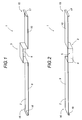
- the burglar protection 1 according to the invention is preferably made from a sheet metal strip 2, preferably of metal.
- This strip of sheet metal 2 for example made of stainless steel or galvanized with a thickness of substantially 20/10 e , is folded or bent to form a protector against anti-force 3 shaped shield forming a burglar-proof housing having a sufficient volume to accommodate the protruding portion of a gauge 4 or a drain plug.
- This anti-intrusion protection projection 3 can be closed on one of its lateral faces 5 or on both lateral faces by means of a shutter plate 6 in order to prevent access to the protruding part of gauge 4 or to a drain plug.
- the protruding protection projection 3 is closed only on one of its sides 5.
- the closure plate 6 is preferably made of the same material as that of the sheet metal strip 2 and is preferably secured to the latter by welding.
- each shutter plate 6 In addition to its function of closing the side of the burglar-proof protector 3, each shutter plate 6 also serves as a reinforcement for the protrusion 3, thus making the structure of the latter more resistant to destruction and deformation in order to deter thieves from taking action.
- the anti-tamper protector protector 3 is in the form of a parallelepiped and the shutter plates 6 are in the form of a rectangle.
- the lower faces 9, 10 of the sheet metal strip 2 of the invention are fastened or permanently secured against the wall 11 of the tank by any means, for example 12 either by gluing or welding, either by a double-sided strip of strong adhesion on each face.
- the fuel tanks 12 trucks are immobilized on a support secured to the frame with two or more straps 13, 14 of maintenance.
- these straps 13, 14 are mounted above the device, that is to say they come cover the end zones, including the ends 15, 16 of the band, then providing additional support and better preventing the removal of the burglar protection 1 of the invention.
- the sheet metal plate 2 of the burglar protection 1 has at each end 15, 16 a transverse side with raised rim 17, 18 forming a raised rim of edge for example by folding, preferably substantially at right angles constituting with the adjacent strap a stop-stop stop in case This raised edge of the band 17, 18 serves to wedge the outer edge of each holding strap 13, 14 of the fuel tank 12.
- the straps 13, 14 may even less be laterally slid, which prevents forced removal of the burglary protection 1 of the invention.
- the straps 13, 14 and the burglar-proof protection 1 of the invention with its raised edge edges 17, 18, provide a mutual hold-stop which prevents slipping under the strap of the burglar-proof protection 1 of the invention.
- This mutual blocking can be further strengthened by folding or bending the raised edges of the transverse edges on the adjacent strap.
- This protection 1 thus offers a burglar-proof solution perfectly adapted to the protection of the gauge passage 4 and the drain plug for the fuel tank 12 of a truck.
Landscapes
- Engineering & Computer Science (AREA)
- Life Sciences & Earth Sciences (AREA)
- Sustainable Development (AREA)
- Sustainable Energy (AREA)
- Chemical & Material Sciences (AREA)
- Combustion & Propulsion (AREA)
- Transportation (AREA)
- Mechanical Engineering (AREA)
- Cooling, Air Intake And Gas Exhaust, And Fuel Tank Arrangements In Propulsion Units (AREA)
- Details Of Rigid Or Semi-Rigid Containers (AREA)
- Closures For Containers (AREA)
- Level Indicators Using A Float (AREA)
Claims (10)
- Vorrichtung zur Diebstahlsicherung (1) gegen die Entnahme des Messgeräts oder die Entfernung der Ablassschraube, die gegen die Seitenwand (11) eines Kraftstoffbehälters (12) montiert ist, gekennzeichnet dadurch, dass sie ein gebogenes oder gewölbtes Blechband (2) umfasst, um einen Schutzaufbau (3) in Form eines Diebstahlschutzgehäuses zu bilden, das ein ausreichendes Volumen aufweist, um das vorstehende Teil eines Messgeräts und/oder einer Ablassschraube unterzubringen, wobei dieses Blechband unbeweglich auf der Seitenwand (11) des Kraftstoffbehälters (12) eingebracht ist.
- Vorrichtung zur Diebstahlsicherung (1) nach Anspruch 1, gekennzeichnet dadurch, dass die Blechplatte (2) mindestens an jedem ihrer zwei Endbereichen durch mindestens einen der mindestens zwei Trag- und Halteriemen (13, 14) des Kraftstoffbehälters (12) abgedeckt ist, wobei diese mindestens zwei Riemen (13, 14) die Enden (15, 16) der Blechplatte bedecken, um sie gegen die Seitenfläche (11) des Behälters (12) aufzudrücken.
- Vorrichtung zur Diebstahlsicherung (1) nach dem vorangehenden Anspruch, gekennzeichnet dadurch, dass die Blechplatte (2) an jedem ihrer Enden (15, 16) eine Querseite mit angehobenem Rand (17, 18) aufweist, um einen angehobenen Kantenrand für das Band zu bilden, das mit dem Riemen einen Anhalteanschlag beim Hochheben des Bandes (2) bildet, wobei diese angehobenen Kantenränder (17, 18) für die Aufnahme der Keilverbindung des äußeren Randes der Halteriemen (13, 14) des Kraftstoffbehälters (12) entlang ihrer Hinterseite vorgesehen sind.
- Vorrichtung zur Diebstahlsicherung (1) nach dem vorangehenden Anspruch, gekennzeichnet dadurch, dass die angehobenen Ränder (17, 18) im rechten Winkel leicht gebogen sind.
- Vorrichtung zur Diebstahlsicherung (1) nach dem vorangehenden Anspruch, gekennzeichnet dadurch, dass die angehobenen Ränder der Querränder auf der Oberseite des benachbarten Riemens umgeklappt oder umgebogen sind.
- Vorrichtung zur Diebstahlsicherung (1) nach einem der vorangehenden Ansprüche, gekennzeichnet dadurch, dass der Diebstahlschutz (3) die Form eines Quaders hat.
- Vorrichtung zur Diebstahlsicherung (1) nach einem der vorangehenden Ansprüche, gekennzeichnet dadurch, dass die Unterseiten (9, 10) des Blechbandes (2) gegen die oder an der Wand (11) des Behälters (12) befestigt werden oder durch Kleben oder Schweißung untereinander verbunden werden.
- Vorrichtung zur Diebstahlsicherung (1) nach einem der vorangehenden Ansprüche, gekennzeichnet dadurch, dass die Unterseiten (9, 10) des Blechbandes (2) gegen die Wand (11) des Behälters (12) durch ein doppelseitiges Klebeband mit starker Anhaftungsfähigkeit auf jeder Seite befestigt werden.
- Vorrichtung zur Diebstahlsicherung (1) nach dem vorangehenden Anspruch, gekennzeichnet dadurch, dass das Blechband (2) aus rostfreiem oder galvanisiertem Stahl ausgeführt ist.
- Vorrichtung zur Diebstahlsicherung (1) nach einem der vorangehenden Ansprüche, gekennzeichnet dadurch, dass der Diebstahlschutz (3) auf mindestens einer seiner Seiten (5) mit Hilfe einer Verschlussplatte (6) verschlossen ist.
Applications Claiming Priority (1)
| Application Number | Priority Date | Filing Date | Title |
|---|---|---|---|
| FR0510123A FR2891498B1 (fr) | 2005-10-04 | 2005-10-04 | Dispositif anti-effraction du passage de jauge ou du bouchon de vidange pour un reservoir de carburant. |
Publications (2)
| Publication Number | Publication Date |
|---|---|
| EP1772302A1 EP1772302A1 (de) | 2007-04-11 |
| EP1772302B1 true EP1772302B1 (de) | 2008-07-02 |
Family
ID=36645705
Family Applications (1)
| Application Number | Title | Priority Date | Filing Date |
|---|---|---|---|
| EP06360046A Active EP1772302B1 (de) | 2005-10-04 | 2006-10-04 | Diebstahlsicherung eines Messgeräts und einer Ablassschraube eines Kraftstoffbehälters |
Country Status (5)
| Country | Link |
|---|---|
| EP (1) | EP1772302B1 (de) |
| AT (1) | ATE399671T1 (de) |
| DE (1) | DE602006001620D1 (de) |
| ES (1) | ES2310896T3 (de) |
| FR (1) | FR2891498B1 (de) |
Families Citing this family (3)
| Publication number | Priority date | Publication date | Assignee | Title |
|---|---|---|---|---|
| FR3027258B1 (fr) * | 2014-10-20 | 2016-12-16 | Lionel Lecrosnier | Systeme de protection d'un bouchon d'un reservoir a carburant |
| ITUB20169960A1 (it) * | 2016-01-13 | 2017-07-13 | Active Fuel Srl | Dispositivo di protezione copripescante per serbatoi |
| FR3129110B1 (fr) * | 2021-11-15 | 2023-10-13 | Soc Dinnovations Techniques Embarquees Et Connectees S I T E C | Dispositif de détection configuré pour détecter le vol de carburant |
Family Cites Families (3)
| Publication number | Priority date | Publication date | Assignee | Title |
|---|---|---|---|---|
| JPS60151128A (ja) * | 1984-01-20 | 1985-08-09 | Nissan Motor Co Ltd | キヤニスタ−ドレインホ−スの配索構造 |
| JPH1014364A (ja) * | 1996-06-28 | 1998-01-20 | Mitsubishi Agricult Mach Co Ltd | 移動農機の操縦部構造 |
| JP3415725B2 (ja) * | 1996-10-18 | 2003-06-09 | 三菱農機株式会社 | 移動農機の燃料タンク装置 |
-
2005
- 2005-10-04 FR FR0510123A patent/FR2891498B1/fr not_active Expired - Fee Related
-
2006
- 2006-10-04 DE DE602006001620T patent/DE602006001620D1/de active Active
- 2006-10-04 AT AT06360046T patent/ATE399671T1/de not_active IP Right Cessation
- 2006-10-04 ES ES06360046T patent/ES2310896T3/es active Active
- 2006-10-04 EP EP06360046A patent/EP1772302B1/de active Active
Also Published As
| Publication number | Publication date |
|---|---|
| EP1772302A1 (de) | 2007-04-11 |
| FR2891498A1 (fr) | 2007-04-06 |
| ATE399671T1 (de) | 2008-07-15 |
| ES2310896T3 (es) | 2009-01-16 |
| FR2891498B1 (fr) | 2008-12-19 |
| DE602006001620D1 (de) | 2008-08-14 |
Similar Documents
| Publication | Publication Date | Title |
|---|---|---|
| EP1772302B1 (de) | Diebstahlsicherung eines Messgeräts und einer Ablassschraube eines Kraftstoffbehälters | |
| FR2580243A1 (fr) | Dispositif de securite antivol pour vehicule automobile | |
| EP2522825B1 (de) | Wärme- und Schallschutzschirm für eine Abgasleitung eines Kraftfahrzeugs | |
| EP3585653A1 (de) | Schutzelement für eine tür und anordnung solch eines elements an einem fahrzeug | |
| FR2799700A1 (fr) | Planche de bord a rigidite amelioree, equipee d'un coussin de protection et ensemble adapte a un vehicule automobile | |
| EP0753450A1 (de) | Vorrichtung zum Seitenaufprallschutz für Kfz-Insassen | |
| EP3356169B1 (de) | Heckklappe mit einer verkleidung zur ermöglichung der reduzierung des siebdrucks des fensters | |
| CA2726663A1 (fr) | Dispositif de protection d'un ouvrant de vehicule | |
| EP1622095A1 (de) | Aufzeichnungsvorrichtung für Prüf- und/oder Überwachungszwecke mit einem Sicherungsetikett | |
| EP2468584B1 (de) | Lenksäule eines Kraftfahrzeugs mit verbesserter Diebstahlsicherungsvorrichtung | |
| EP1239086A1 (de) | Verbesserte Sicherheitsverschlussvorrichtung | |
| FR2463694A3 (fr) | Dispositif pour empecher le vol de carburant dans un reservoir, notamment de vehicule automobile | |
| EP0113302B1 (de) | Panzerschrank | |
| FR2919002A1 (fr) | Dispositif de voirie a cadre de support et element de couronnement, tel qu'un tampon ou couvercle, monte articule a basculement sur le cadre | |
| FR2923850A1 (fr) | Predalle pourvue d'un obturateur delimitant une ouverture de cette predalle. | |
| WO2016102791A1 (fr) | Dispositif anti-bourdonnement pour porte de coffre | |
| EP1500613A1 (de) | Müllbehälter, insbesondere zur Verwendung im öffenlichen Bereich | |
| EP3581739B1 (de) | Schutzvorrichtung für entriegelungsmechanismus eines türschlosses vom typ mit flächenbündigem griff | |
| EP1661827B1 (de) | Halbunterirdischer Behälter zum Sammeln von Müll | |
| EP4204119B1 (de) | Kraftstofffiltersystem mit sicherheitsstift | |
| EP1477355B1 (de) | Autotür mit Schutztsmitteln des oberen Bereichs einer flachmontierten Scheibe, Erweiterung des Schutzes und Fahrzeug hierzu. | |
| EP0438946B1 (de) | Tresoranlage umfassend eine Eingabevorrichtung verbunden an einen Wertschrank | |
| FR2760702A1 (fr) | Cellule evolutive pour vehicule | |
| EP1243451A1 (de) | Seitenschutzeinrichtung für Kraftfahrzeug | |
| FR3142500A1 (fr) | Support de serrure d’un ouvrant d’un véhicule |
Legal Events
| Date | Code | Title | Description |
|---|---|---|---|
| PUAI | Public reference made under article 153(3) epc to a published international application that has entered the european phase |
Free format text: ORIGINAL CODE: 0009012 |
|
| AK | Designated contracting states |
Kind code of ref document: A1 Designated state(s): AT BE BG CH CY CZ DE DK EE ES FI FR GB GR HU IE IS IT LI LT LU LV MC NL PL PT RO SE SI SK TR |
|
| AX | Request for extension of the european patent |
Extension state: AL BA HR MK YU |
|
| RAP1 | Party data changed (applicant data changed or rights of an application transferred) |
Owner name: MOUGENOT PROTECTION INNOVATIONS |
|
| RIN1 | Information on inventor provided before grant (corrected) |
Inventor name: MOUGENOT PROTECTION INNOVATIONS |
|
| 17P | Request for examination filed |
Effective date: 20071004 |
|
| AKX | Designation fees paid |
Designated state(s): AT BE BG CH CY CZ DE DK EE ES FI FR GB GR HU IE IS IT LI LT LU LV MC NL PL PT RO SE SI SK TR |
|
| AXX | Extension fees paid |
Extension state: HR Payment date: 20061227 Extension state: YU Payment date: 20061227 Extension state: AL Payment date: 20061227 Extension state: BA Payment date: 20061227 |
|
| GRAP | Despatch of communication of intention to grant a patent |
Free format text: ORIGINAL CODE: EPIDOSNIGR1 |
|
| RIN1 | Information on inventor provided before grant (corrected) |
Inventor name: L'INVENTEUR A RENONCE A SA DESIGNATION. |
|
| RAX | Requested extension states of the european patent have changed |
Extension state: BA Payment date: 20061227 Extension state: RS Payment date: 20061227 Extension state: AL Payment date: 20061227 Extension state: HR Payment date: 20061227 |
|
| RIN1 | Information on inventor provided before grant (corrected) |
Inventor name: MOUGENOT PHILIPPE |
|
| GRAS | Grant fee paid |
Free format text: ORIGINAL CODE: EPIDOSNIGR3 |
|
| GRAA | (expected) grant |
Free format text: ORIGINAL CODE: 0009210 |
|
| AK | Designated contracting states |
Kind code of ref document: B1 Designated state(s): AT BE BG CH CY CZ DE DK EE ES FI FR GB GR HU IE IS IT LI LT LU LV MC NL PL PT RO SE SI SK TR |
|
| AX | Request for extension of the european patent |
Extension state: AL BA HR RS |
|
| REG | Reference to a national code |
Ref country code: GB Ref legal event code: FG4D Free format text: NOT ENGLISH |
|
| REG | Reference to a national code |
Ref country code: CH Ref legal event code: EP |
|
| REF | Corresponds to: |
Ref document number: 602006001620 Country of ref document: DE Date of ref document: 20080814 Kind code of ref document: P |
|
| REG | Reference to a national code |
Ref country code: IE Ref legal event code: FG4D Free format text: LANGUAGE OF EP DOCUMENT: FRENCH |
|
| PG25 | Lapsed in a contracting state [announced via postgrant information from national office to epo] |
Ref country code: SI Free format text: LAPSE BECAUSE OF FAILURE TO SUBMIT A TRANSLATION OF THE DESCRIPTION OR TO PAY THE FEE WITHIN THE PRESCRIBED TIME-LIMIT Effective date: 20080702 |
|
| PG25 | Lapsed in a contracting state [announced via postgrant information from national office to epo] |
Ref country code: NL Free format text: LAPSE BECAUSE OF FAILURE TO SUBMIT A TRANSLATION OF THE DESCRIPTION OR TO PAY THE FEE WITHIN THE PRESCRIBED TIME-LIMIT Effective date: 20080702 |
|
| NLV1 | Nl: lapsed or annulled due to failure to fulfill the requirements of art. 29p and 29m of the patents act | ||
| REG | Reference to a national code |
Ref country code: ES Ref legal event code: FG2A Ref document number: 2310896 Country of ref document: ES Kind code of ref document: T3 |
|
| PG25 | Lapsed in a contracting state [announced via postgrant information from national office to epo] |
Ref country code: LT Free format text: LAPSE BECAUSE OF FAILURE TO SUBMIT A TRANSLATION OF THE DESCRIPTION OR TO PAY THE FEE WITHIN THE PRESCRIBED TIME-LIMIT Effective date: 20080702 Ref country code: IS Free format text: LAPSE BECAUSE OF FAILURE TO SUBMIT A TRANSLATION OF THE DESCRIPTION OR TO PAY THE FEE WITHIN THE PRESCRIBED TIME-LIMIT Effective date: 20081102 |
|
| PG25 | Lapsed in a contracting state [announced via postgrant information from national office to epo] |
Ref country code: PT Free format text: LAPSE BECAUSE OF FAILURE TO SUBMIT A TRANSLATION OF THE DESCRIPTION OR TO PAY THE FEE WITHIN THE PRESCRIBED TIME-LIMIT Effective date: 20081202 Ref country code: LV Free format text: LAPSE BECAUSE OF FAILURE TO SUBMIT A TRANSLATION OF THE DESCRIPTION OR TO PAY THE FEE WITHIN THE PRESCRIBED TIME-LIMIT Effective date: 20080702 Ref country code: AT Free format text: LAPSE BECAUSE OF FAILURE TO SUBMIT A TRANSLATION OF THE DESCRIPTION OR TO PAY THE FEE WITHIN THE PRESCRIBED TIME-LIMIT Effective date: 20080702 Ref country code: FI Free format text: LAPSE BECAUSE OF FAILURE TO SUBMIT A TRANSLATION OF THE DESCRIPTION OR TO PAY THE FEE WITHIN THE PRESCRIBED TIME-LIMIT Effective date: 20080702 Ref country code: BG Free format text: LAPSE BECAUSE OF FAILURE TO SUBMIT A TRANSLATION OF THE DESCRIPTION OR TO PAY THE FEE WITHIN THE PRESCRIBED TIME-LIMIT Effective date: 20081002 |
|
| REG | Reference to a national code |
Ref country code: IE Ref legal event code: FD4D |
|
| PG25 | Lapsed in a contracting state [announced via postgrant information from national office to epo] |
Ref country code: IE Free format text: LAPSE BECAUSE OF FAILURE TO SUBMIT A TRANSLATION OF THE DESCRIPTION OR TO PAY THE FEE WITHIN THE PRESCRIBED TIME-LIMIT Effective date: 20080702 Ref country code: EE Free format text: LAPSE BECAUSE OF FAILURE TO SUBMIT A TRANSLATION OF THE DESCRIPTION OR TO PAY THE FEE WITHIN THE PRESCRIBED TIME-LIMIT Effective date: 20080702 Ref country code: DK Free format text: LAPSE BECAUSE OF FAILURE TO SUBMIT A TRANSLATION OF THE DESCRIPTION OR TO PAY THE FEE WITHIN THE PRESCRIBED TIME-LIMIT Effective date: 20080702 |
|
| PLBE | No opposition filed within time limit |
Free format text: ORIGINAL CODE: 0009261 |
|
| STAA | Information on the status of an ep patent application or granted ep patent |
Free format text: STATUS: NO OPPOSITION FILED WITHIN TIME LIMIT |
|
| PG25 | Lapsed in a contracting state [announced via postgrant information from national office to epo] |
Ref country code: RO Free format text: LAPSE BECAUSE OF FAILURE TO SUBMIT A TRANSLATION OF THE DESCRIPTION OR TO PAY THE FEE WITHIN THE PRESCRIBED TIME-LIMIT Effective date: 20080702 Ref country code: MC Free format text: LAPSE BECAUSE OF NON-PAYMENT OF DUE FEES Effective date: 20081031 Ref country code: SK Free format text: LAPSE BECAUSE OF FAILURE TO SUBMIT A TRANSLATION OF THE DESCRIPTION OR TO PAY THE FEE WITHIN THE PRESCRIBED TIME-LIMIT Effective date: 20080702 Ref country code: CZ Free format text: LAPSE BECAUSE OF FAILURE TO SUBMIT A TRANSLATION OF THE DESCRIPTION OR TO PAY THE FEE WITHIN THE PRESCRIBED TIME-LIMIT Effective date: 20080702 |
|
| 26N | No opposition filed |
Effective date: 20090403 |
|
| PG25 | Lapsed in a contracting state [announced via postgrant information from national office to epo] |
Ref country code: SE Free format text: LAPSE BECAUSE OF FAILURE TO SUBMIT A TRANSLATION OF THE DESCRIPTION OR TO PAY THE FEE WITHIN THE PRESCRIBED TIME-LIMIT Effective date: 20081002 |
|
| PG25 | Lapsed in a contracting state [announced via postgrant information from national office to epo] |
Ref country code: PL Free format text: LAPSE BECAUSE OF FAILURE TO SUBMIT A TRANSLATION OF THE DESCRIPTION OR TO PAY THE FEE WITHIN THE PRESCRIBED TIME-LIMIT Effective date: 20080702 |
|
| PG25 | Lapsed in a contracting state [announced via postgrant information from national office to epo] |
Ref country code: HU Free format text: LAPSE BECAUSE OF FAILURE TO SUBMIT A TRANSLATION OF THE DESCRIPTION OR TO PAY THE FEE WITHIN THE PRESCRIBED TIME-LIMIT Effective date: 20090103 Ref country code: CY Free format text: LAPSE BECAUSE OF FAILURE TO SUBMIT A TRANSLATION OF THE DESCRIPTION OR TO PAY THE FEE WITHIN THE PRESCRIBED TIME-LIMIT Effective date: 20080702 Ref country code: LU Free format text: LAPSE BECAUSE OF NON-PAYMENT OF DUE FEES Effective date: 20081004 |
|
| PG25 | Lapsed in a contracting state [announced via postgrant information from national office to epo] |
Ref country code: TR Free format text: LAPSE BECAUSE OF FAILURE TO SUBMIT A TRANSLATION OF THE DESCRIPTION OR TO PAY THE FEE WITHIN THE PRESCRIBED TIME-LIMIT Effective date: 20080702 |
|
| PG25 | Lapsed in a contracting state [announced via postgrant information from national office to epo] |
Ref country code: GR Free format text: LAPSE BECAUSE OF FAILURE TO SUBMIT A TRANSLATION OF THE DESCRIPTION OR TO PAY THE FEE WITHIN THE PRESCRIBED TIME-LIMIT Effective date: 20081003 |
|
| REG | Reference to a national code |
Ref country code: CH Ref legal event code: PL |
|
| PG25 | Lapsed in a contracting state [announced via postgrant information from national office to epo] |
Ref country code: CH Free format text: LAPSE BECAUSE OF NON-PAYMENT OF DUE FEES Effective date: 20101031 Ref country code: LI Free format text: LAPSE BECAUSE OF NON-PAYMENT OF DUE FEES Effective date: 20101031 |
|
| REG | Reference to a national code |
Ref country code: FR Ref legal event code: PLFP Year of fee payment: 10 |
|
| REG | Reference to a national code |
Ref country code: FR Ref legal event code: PLFP Year of fee payment: 11 |
|
| PGFP | Annual fee paid to national office [announced via postgrant information from national office to epo] |
Ref country code: DE Payment date: 20161013 Year of fee payment: 11 Ref country code: GB Payment date: 20161014 Year of fee payment: 11 |
|
| PGFP | Annual fee paid to national office [announced via postgrant information from national office to epo] |
Ref country code: ES Payment date: 20161027 Year of fee payment: 11 Ref country code: BE Payment date: 20161019 Year of fee payment: 11 Ref country code: IT Payment date: 20161011 Year of fee payment: 11 |
|
| REG | Reference to a national code |
Ref country code: FR Ref legal event code: PLFP Year of fee payment: 12 |
|
| REG | Reference to a national code |
Ref country code: DE Ref legal event code: R119 Ref document number: 602006001620 Country of ref document: DE |
|
| GBPC | Gb: european patent ceased through non-payment of renewal fee |
Effective date: 20171004 |
|
| PG25 | Lapsed in a contracting state [announced via postgrant information from national office to epo] |
Ref country code: GB Free format text: LAPSE BECAUSE OF NON-PAYMENT OF DUE FEES Effective date: 20171004 Ref country code: DE Free format text: LAPSE BECAUSE OF NON-PAYMENT OF DUE FEES Effective date: 20180501 |
|
| REG | Reference to a national code |
Ref country code: BE Ref legal event code: MM Effective date: 20171031 |
|
| PG25 | Lapsed in a contracting state [announced via postgrant information from national office to epo] |
Ref country code: BE Free format text: LAPSE BECAUSE OF NON-PAYMENT OF DUE FEES Effective date: 20171031 |
|
| REG | Reference to a national code |
Ref country code: FR Ref legal event code: PLFP Year of fee payment: 13 |
|
| PG25 | Lapsed in a contracting state [announced via postgrant information from national office to epo] |
Ref country code: IT Free format text: LAPSE BECAUSE OF NON-PAYMENT OF DUE FEES Effective date: 20171004 |
|
| REG | Reference to a national code |
Ref country code: ES Ref legal event code: FD2A Effective date: 20181220 |
|
| PG25 | Lapsed in a contracting state [announced via postgrant information from national office to epo] |
Ref country code: ES Free format text: LAPSE BECAUSE OF NON-PAYMENT OF DUE FEES Effective date: 20171005 |
|
| PGFP | Annual fee paid to national office [announced via postgrant information from national office to epo] |
Ref country code: FR Payment date: 20251028 Year of fee payment: 20 |