EP1769977A2 - Roll-Over protection system for motor vehicles with an upraising Roll-Over body - Google Patents
Roll-Over protection system for motor vehicles with an upraising Roll-Over body Download PDFInfo
- Publication number
- EP1769977A2 EP1769977A2 EP06120859A EP06120859A EP1769977A2 EP 1769977 A2 EP1769977 A2 EP 1769977A2 EP 06120859 A EP06120859 A EP 06120859A EP 06120859 A EP06120859 A EP 06120859A EP 1769977 A2 EP1769977 A2 EP 1769977A2
- Authority
- EP
- European Patent Office
- Prior art keywords
- protection system
- rollover protection
- roll
- vehicle
- longitudinal direction
- Prior art date
- Legal status (The legal status is an assumption and is not a legal conclusion. Google has not performed a legal analysis and makes no representation as to the accuracy of the status listed.)
- Granted
Links
Images


Classifications
-
- B—PERFORMING OPERATIONS; TRANSPORTING
- B60—VEHICLES IN GENERAL
- B60R—VEHICLES, VEHICLE FITTINGS, OR VEHICLE PARTS, NOT OTHERWISE PROVIDED FOR
- B60R21/00—Arrangements or fittings on vehicles for protecting or preventing injuries to occupants or pedestrians in case of accidents or other traffic risks
- B60R21/02—Occupant safety arrangements or fittings, e.g. crash pads
- B60R21/13—Roll-over protection
- B60R2021/132—Roll bars for convertible vehicles
- B60R2021/134—Roll bars for convertible vehicles movable from a retracted to a protection position
- B60R2021/135—Roll bars for convertible vehicles movable from a retracted to a protection position automatically during an accident
Definitions
- the invention relates to a rollover protection system for motor vehicles, with two sensor-controlled by a drive from a basic position can be placed in a support position, ironing heads having roll bars seat-related in a vehicle-fixed carrier body pivotally about an axis in the vehicle longitudinal direction (X) spaced side by side perpendicular to the respective axis, are articulated.
- Such rollover protection systems serve to protect the occupants in motor vehicles without a protective roof, typically in convertibles or roadsters during a rollover, since the vehicle will roll over the deployed rollover body, which provides the occupants with a survival space.
- Such a cassette construction of a roll bar protection system with a U-shaped roll bar shows, for example, the DE 100 40 642 C1 ,
- cassette constructions and the cross-member constructions are marketed and in operation in various embodiments adapted to the particular type of vehicle.
- the roll bars are mounted substantially vertically linearly adjustable.
- a rollover protection construction which has two, with respect to the vehicle transverse direction, juxtaposed roll bar, which are each pivotable about an essentially in the vehicle longitudinal direction, the so-called X-direction, pivot axis, and thus in the event of danger from a lowered Resting position in an upwardly directed support position (and later back) are pivotable.
- These roll bars are referred to below as a turn bar.
- the DE 39 25 513 A1 additionally shows the associated frame structure for receiving the two rotating bars and the associated components of the rollover protection system such as the drive of the rotating bar, locking device (re-entry lock), etc.
- the two juxtaposed rotating stirrups are aligned in a plane transverse to the vehicle longitudinal direction, i. at the same height in the X direction, rotatably articulated.
- the height of the Matterrolltangente determining height dimension of the rotating bar is limited because the stored turntable can touch maximum, with a predetermined minimum distance, forehead-to-forehead. Especially with medium and small vehicles that have a limited vehicle width, the available in the vehicle between the side walls of the body is not sufficient to integrate rotary bar with a height that ensure the necessary high Studentsrolltangente.
- the invention has the object of providing the above-described rollover protection system with respect to the accommodation of the rotating bracket in such a way that even in medium and small vehicles, a height of the rotating bar is achievable, which ensures the necessary high Studentsrolltangente for obtaining a safe survival space in the vehicle.
- swivel bars which overlap in the stored state, at least in the bow head area
- swivel bars can be used with a large height, which also in small and medium vehicles a large cantilevered support height and thus a relatively high-lying, the survival space bounding Matterrolltangente is achieved ,
- the figures show a rollover protection system for motor vehicles, in particular for convertibles of medium or smaller vehicles, in which in a fixed vehicle body, e.g. in a schematically illustrated base frame 1, which is screwed by means of two mounting bracket 1 b to the body, two roll bars 2, so-called swivel bracket, are articulated in bearings 3 about the vehicle longitudinal direction pivotally side by side transversely to this direction.
- a fixed vehicle body e.g. in a schematically illustrated base frame 1, which is screwed by means of two mounting bracket 1 b to the body
- two roll bars 2 so-called swivel bracket
- Each of these swivel bracket 2 has a base part 2 a and a rounded bracket head 2 b.
- the ironing head 2 b may have different geometric configurations.
- the roll bars are typically metal parts, which are manufactured by relevant methods, typically the ironing heads are foamed with a plastic.
- the necessary drives, re-entry locks, sensors and the other usual components of a rollover protection system are not shown. You can, for example, by known means, as in the above-cited DE 39 25 513 A1 represented, realized.
- the base frame 1 advantageously has a cutout 1 a for a through-loading possibility.
- a schematically illustrated cover 4 is symbolic of a visually appealing integration of the system in the vehicle.
- the roll bar 2 with its base parts 2 a offset in the vehicle longitudinal direction hinged to each other, such that the ironing heads 2 b overlap in the stored state, i. at least partially overlap.
- the ironing heads can have a greater height dimension than in the known case and as a result of this a high roll-over tangent, even in small and medium vehicles, span.
- the figure 7 shows a variant in which the swivel bracket are hinged with their base parts 2 a at the same height, ie without offset in the vehicle longitudinal direction, the associated ironing heads 2 b, however, have smaller dimensions in this axis than the base parts, based on the two turning bracket complementary to each other, so that the ironing heads 2 b are overlapped in the basic position can be stored.
Abstract
Description
Die Erfindung bezieht sich auf ein Überrollschutzsystem für Kraftfahrzeuge, mit zwei sensorgesteuert mittels eines Antriebes aus einer Grundstellung in eine Stützstellung aufstellbaren, Bügelköpfe aufweisenden Überrollbügeln, die sitzbezogen in einem fahrzeugfesten Trägerkörper verschwenkbar um eine Achse in Fahrzeuglängsrichtung (X) beabstandet nebeneinander senkrecht zur jeweiligen Achse, angelenkt sind.The invention relates to a rollover protection system for motor vehicles, with two sensor-controlled by a drive from a basic position can be placed in a support position, ironing heads having roll bars seat-related in a vehicle-fixed carrier body pivotally about an axis in the vehicle longitudinal direction (X) spaced side by side perpendicular to the respective axis, are articulated.
Derartige Überrollschutzsysteme dienen zum Schutz der Insassen in Kraftfahrzeugen ohne schützendes Dach, typischerweise in Cabriolets oder Roadstern bei einem Überschlag, da das Fahrzeug über den aufgestellten Überrollkörper abrollen wird, der den Insassen einen Überlebensraum bietet.Such rollover protection systems serve to protect the occupants in motor vehicles without a protective roof, typically in convertibles or roadsters during a rollover, since the vehicle will roll over the deployed rollover body, which provides the occupants with a survival space.
Es ist dabei bekannt, einen die gesamte Fahrzeugbreite überspannenden, fest installierten Überrollbügel vorzusehen. Bei dieser Lösung wird der erhöhte Luftwiderstand und das Auftreten von Fahrgeräuschen als nachteilig empfunden, abgesehen von der Beeinträchtigung des Fahrzeugaussehens.It is known to provide a full vehicle width spanning, permanently installed roll bar. In this solution, the increased air resistance and the occurrence of driving noise is perceived as disadvantageous, apart from the impairment of the vehicle appearance.
Es ist auch bekannt, jedem Fahrzeugsitz einen höhenunveränderlich fest installierten, d.h. starren, U-förmigen Überrollbügel zuzuordnen. Diese Lösung wird typischerweise bei Roadstern zur Unterstreichung des sportlichen Aussehens eingesetzt.It is also known to have each vehicle seat installed in a height-invariable manner, i. rigid to assign U-shaped roll bar. This solution is typically used in roadsters to underline the sporty appearance.
Weit verbreitet bei Cabriolets sind konstruktive Lösungen, bei denen der Überrollkörper im Normalzustand eingefahren ist, und im Gefahrenfall, also bei einem drohenden Überschlag, sehr schnell in eine schützende Position aufgestellt wird, um zu verhindern, dass die Fahrzeuginsassen durch das sich überschlagende Fahrzeug erdrückt werden.Widely used in convertibles are constructive solutions in which the rollover body is retracted in the normal state, and in case of danger, so in a threatening rollover, very quickly in a protective Position is set to prevent the vehicle occupants are crushed by the overturning vehicle.
Diese sogenannten "aktiven" Überrollschutzsysteme weisen typischerweise einen in einem fahrzeugfesten Führungskörper geführten U-förmigen Überrollbügel oder aus einem Profilkörper gebildeten Überrollkörper auf, wobei der Führungskörper in einem Kassetten-Gehäuse, das Seitenteile und ein Bodenteil aufweist, befestigt ist. Dieser Überrollbügel bzw. Überrollkörper wird im Normalzustand gegen die Vorspannkraft mindestens einer Antriebs-Druckfeder durch eine Haltevorrichtung in einer unteren Ruhelage gehalten, und ist im Überschlagfall, sensorgesteuert unter Lösen der Haltevorrichtung, durch die Federkraft der Antriebs-Druckfeder in eine obere, schützende Stellung bringbar, wobei eine dann in verzahnenden Wirkeingriff tretende Verriegelungseinrichtung, die Wiedereinfahrsperre, ein Zurückdrücken des Überrollbügels verhindert. Dabei ist typischerweise jedem Fahrzeugsitz eine Kassette zugeordnet.These so-called "active" rollover protection systems typically have a guided in a vehicle-fixed guide body U-shaped roll bar or rollover body formed from a profile body, wherein the guide body in a cassette housing having side parts and a bottom part is attached. This roll bar or rollover body is held in the normal state against the biasing force of at least one drive compression spring by a holding device in a lower rest position, and is in the rollover case, sensor controlled releasing the holding device, brought by the spring force of the drive compression spring in an upper, protective position , wherein a then entering into intermeshing operative engagement locking device, the reentrant lock, a pushing back of the roll bar. Typically, each vehicle seat is associated with a cassette.
Eine derartige Kassetten-Konstruktion eines Überrollbügelschutzsystems mit einem U-förmigen Überrollbügel zeigt beispielsweise die
Neben den Kassetten-Konstruktionen sind auch aktive Überrollschutzsysteme nach einem Konstruktionsprinzip mit einer Rückwand-Baueinheit bekannt, wie es beispielsweise in der
Sowohl die Kassetten-Konstruktionen als auch die Querträger-Konstruktionen sind in vielfältigen Ausführungsformen, angepasst an den jeweiligen Fahrzeugtyp, auf dem Markt eingeführt und in Betrieb.Both the cassette constructions and the cross-member constructions are marketed and in operation in various embodiments adapted to the particular type of vehicle.
Bei beiden Konstruktionen sind die Überrollbügel im wesentlichen vertikal linear aufstellbar gehaltert. Es ist jedoch auch eine Überrollschutz-Konstruktion bekannt, die zwei, bezogen auf die Fahrzeugquerrichtung, nebeneinander angeordnete Überrollbügel aufweist, die jeweils um eine im wesentlichen in Fahrzeuglängsrichtung, der sogenannten X-Richtung, verlaufenden Schwenkachse schwenkbar sind, und somit im Gefahrenfall aus einer abgesenkten Ruhelage in eine nach oben gerichtete Stützlage (und später zurück) schwenkbar sind. Diese Überrollbügel werden im folgenden als Drehbügel bezeichnet.In both constructions, the roll bars are mounted substantially vertically linearly adjustable. However, it is also a rollover protection construction is known, which has two, with respect to the vehicle transverse direction, juxtaposed roll bar, which are each pivotable about an essentially in the vehicle longitudinal direction, the so-called X-direction, pivot axis, and thus in the event of danger from a lowered Resting position in an upwardly directed support position (and later back) are pivotable. These roll bars are referred to below as a turn bar.
Eine derartige Konstruktion zeigen die
Der Wunsch der Fahrzeughersteller nach einem aktiven Überrollschutzsystem setzt sich aufgrund des gestiegenen Sicherheitsbewusstseins verstärkt auch in Richtung auf mittlere und kleine Fahrzeuge fort. Aufgrund der geringeren Einbauräume in solchen Fahrzeugen sind hierbei besondere Überlegungen anzustellen, um Überrollbügel mit der notwendigen hohen Überrolltangente unterzubringen. Es hat sich gezeigt, dass das vorbekannte System mit Drehbügeln, die sich aus der abgesenkten Ruhelage quer zur Fahrzeuglängsrichtung drehend aufstellen, eine gute Basis für die vorgenannten Überlegungen zur Lösung der entsprechenden Probleme gibt.The desire of the vehicle manufacturers for an active rollover protection system continues due to the increased safety awareness increasingly in the direction of medium and small vehicles. Due to the smaller installation spaces in such vehicles, special considerations must be made to accommodate roll bars with the necessary high rollover tangent. It has been shown that the previously known system with rotating brackets, which rotate from the lowered rest position transverse to the vehicle longitudinal direction, provides a good basis for the above considerations to solve the corresponding problems.
Von einem derartigen System mit Drehbügeln geht auch die Erfindung aus.From such a system with rotating bars, the invention is also based.
Im bekannten Fall sind die beiden nebeneinander angeordneten Drehbügel fluchtend in einer Ebene quer zur Fahrzeuglängsrichtung, d.h. auf gleicher Höhe in der X-Richtung, drehbar angelenkt.In the known case, the two juxtaposed rotating stirrups are aligned in a plane transverse to the vehicle longitudinal direction, i. at the same height in the X direction, rotatably articulated.
Das die Höhe der Überrolltangente bestimmende Höhenmaß der Drehbügel ist dadurch begrenzt, weil sich die abgelegten Drehbügel maximal, mit vorgegebenem Minimalabstand, Stirn-an-Stirn berühren können. Gerade bei mittleren und kleinen Fahrzeugen, die eine begrenzte Fahrzeugbreite aufweisen, reicht das im Fahrzeug zur Verfügung stehende Maß zwischen den Seitenwänden der Karosserie nicht aus, Drehbügel mit einem Höhenmaß zu integrieren, welche die notwendige hohe Überrolltangente gewährleisten.The height of the Überrolltangente determining height dimension of the rotating bar is limited because the stored turntable can touch maximum, with a predetermined minimum distance, forehead-to-forehead. Especially with medium and small vehicles that have a limited vehicle width, the available in the vehicle between the side walls of the body is not sufficient to integrate rotary bar with a height that ensure the necessary high Überrolltangente.
Der Erfindung liegt die Aufgabe zugrunde, das eingangs bezeichnete Überrollschutzsystem hinsichtlich der Unterbringung der Drehbügel so auszubilden, dass auch bei mittleren und kleinen Fahrzeugen ein Höhenmaß der Drehbügel erzielbar ist, welches die notwendige hohe Überrolltangente für den Erhalt eines sicheren Überlebensraumes im Fahrzeug gewährleistet.The invention has the object of providing the above-described rollover protection system with respect to the accommodation of the rotating bracket in such a way that even in medium and small vehicles, a height of the rotating bar is achievable, which ensures the necessary high Überrolltangente for obtaining a safe survival space in the vehicle.
Die Lösung dieser Aufgabe gelingt bei einem Überrollschutzsystem für Kraftfahrzeuge, mit zwei sensorgesteuert mittels eines Antriebes aus einer Grundstellung in eine Stützstellung aufstellbaren, Bügelköpfe aufweisenden Überrollbügeln, die sitzbezogen in einem fahrzeugfesten Trägerkörper verschwenkbar um eine Achse in Fahrzeuglängsrichtung (X) beabstandet nebeneinander senkrecht zur jeweiligen Achse, angelenkt sind, gemäß der Erfindung dadurch, dass die Überrollbügel so angelenkt sind, dass sie zumindest mit ihren Bügelköpfen und dabei zumindest teilweise überlappend versetzt in der Fahrzeuglängsrichtung in die Grundstellung ablegbar sind.The solution to this problem is achieved in a rollover protection system for motor vehicles, with two sensor controlled by a drive from a basic position can be placed in a support position, ironing heads having roll bars seat-related in a vehicle-fixed carrier body pivotally about an axis in the vehicle longitudinal direction (X) spaced side by side perpendicular to the respective axis , hinged are, according to the invention characterized in that the roll bars are articulated so that they are at least partially overlapping offset in the vehicle longitudinal direction in the basic position can be stored at least with their bow heads.
Durch diese erfindungsgemäßen Maßnahmen mit Drehbügeln, die sich im abgelegten Zustand zumindest im Bügelkopfbereich überlappen, können Drehbügel mit einem großen Höhenmaß eingesetzt werden, wodurch auch gerade bei kleinen und mittleren Fahrzeugen eine große überkragende Abstützhöhe und damit eine relativ hochliegende, den Überlebensraum umgrenzende Überrolltangente erreicht wird.By these measures according to the invention with swivel bars, which overlap in the stored state, at least in the bow head area, swivel bars can be used with a large height, which also in small and medium vehicles a large cantilevered support height and thus a relatively high-lying, the survival space bounding Überrolltangente is achieved ,
Ausgestaltungen und Weiterbildungen der Erfindung sind in Unteransprüchen gekennzeichnet und ergeben sich auch aus der Figurenbeschreibung.Embodiments and further developments of the invention are characterized in dependent claims and also result from the description of the figures.
Anhand eines in den Zeichnungen in verschiedenen Ansichten und Zuständen dargestellten Ausführungsbeispieles einschließlich einer abgewandelten Variante wird die Erfindung näher beschrieben:Reference to an embodiment shown in the drawings in various views and states including a modified variant of the invention is described in more detail:
Es zeigen:
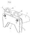
- Fig. 1
- in einer perspektivischen Darstellung eine aktive Überrollschutz-Vorrichtung für Kraftfahrzeuge mit aufgestellten Drehbügeln, die in einem fahrzeugfesten Trägerkörper versetzt zueinander in Fahrzeuglängsrichtung und überlappbar mit ihren Bügelköpfen nebeneinander quer zu dieser Längsrichtung angelenkt sind,
- Fig. 2
- die Vorrichtung nach Fig. 1 in einer Ausschnitt-Darstellung mit teilweise weggebrochenem Trägerkörper, wobei ein Drehbügel aufgestellt und der andere abgelegt ist,
- Fig. 3
- die Vorrichtung nach Fig. 1 mit abgelegten Drehbügeln,
- Fig. 4
- die Vorrichtung nach Fig. 2, jedoch mit beiden Drehbügeln im abgelegten Zustand,
- Fig. 5
- eine Vorderansicht der Vorrichtung nach Fig. 1 ohne Frontwand des Trägerkörpers,
- Fig. 6
- eine Querschnitt-Darstellung der versetzt und überschneidend abgelegten Drehbügel, und
- Fig. 7
- in einer schematisierten Draufsicht eine Variante des Ausführungsbeispieles, bei welcher die Drehbügel auf gleicher Höhe in Fahrzeuglängsrichtung angelenkt sind, jedoch Bügelköpfe mit geringeren Abmaßen in dieser Richtung aufweisen.
- Fig. 1
- in a perspective view of an active rollover protection device for motor vehicles with erected turnbuckles, which are articulated in a vehicle-fixed support body offset from each other in the vehicle longitudinal direction and overlapped with their temple heads side by side transversely to this longitudinal direction,
- Fig. 2
- 1 in a cut-away view with partially broken-away carrier body, wherein a turntable is set up and the other is stored,
- Fig. 3
- the apparatus of Figure 1 with stored swivel bars,
- Fig. 4
- the device according to Fig. 2, but with both turning brackets in the stored state,
- Fig. 5
- a front view of the device of Figure 1 without front wall of the carrier body,
- Fig. 6
- a cross-sectional view of the staggered and overlapping stored swivel bracket, and
- Fig. 7
- in a schematic plan view of a variant of the embodiment, in which the swivel bracket are articulated at the same height in the vehicle longitudinal direction, but have ironing heads with smaller dimensions in this direction.
Die Figuren zeigen ein Überrollschutzsystem für Kraftfahrzeuge, insbesondere für Cabriolets mittlerer oder kleinerer Fahrzeuge, bei dem in einem fahrzeugfest angebrachten Trägerkörper, z.B. in einem schematisiert dargestellten Grundrahmen 1, der mittels zweier Befestigungswinkel 1 b an der Karosserie angeschraubt ist, zwei Überrollbügel 2, sogenannte Drehbügel, in Lagern 3 um die Fahrzeuglängsrichtung verschwenkbar nebeneinander quer zu dieser Richtung angelenkt sind. Jeder dieser Drehbügel 2 weist ein Basisteil 2 a und einen gerundeten Bügelkopf 2 b auf. Der Bügelkopf 2 b kann unterschiedliche geometrische Konfigurationen haben. Vorzugsweise ist er jedoch, entweder bogenförmig bzw. nach Art einer "Ochsenzunge" wie dargestellt, oder U-förmig mit langgestreckten Bügelschenkeln, die am Basisteil befestigt sind, ausgebildet. Er bestimmt maßgebend das für eine hohe Überrolltangente notwendige Höhenmaß.The figures show a rollover protection system for motor vehicles, in particular for convertibles of medium or smaller vehicles, in which in a fixed vehicle body, e.g. in a schematically illustrated
Die Überrollbügel sind typischerweise Metallteile, die nach einschlägigen Verfahren hergestellt werden, wobei typischerweise die Bügelköpfe mit einem Kunststoff umschäumt sind.The roll bars are typically metal parts, which are manufactured by relevant methods, typically the ironing heads are foamed with a plastic.
In der Grundstellung gemäß den Figuren 3 bis 6 sind die Überrollbügel 2 waagrecht liegend, bündig mit der Fahrzeugbrüstung abschließend, angelenkt. Im Fall eines drohenden Überschlages werden sie sehr schnell, d.h. im ms-Bereich, in die Stützstellung hochgeschwenkt, wie es in den Figuren 1 und 2 (teilweise) dargestellt ist.In the normal position according to FIGS. 3 to 6, the
Die notwendigen Antriebe, Wiedereinfahrsperren, Sensorik sowie die übrigen, üblichen Komponenten eines Überroll-Schutzsystems sind nicht dargestellt. Sie können beispielsweise mit bekannten Mitteln, wie in der eingangs zitierten
Erfindungsgemäß sind, wie insbesondere die Figuren 4 - 6 zeigen, durch entsprechende Ausbildung der Lager 3 die Überrollbügel 2 mit ihren Basisteilen 2 a in der Fahrzeuglängsrichtung versetzt zueinander angelenkt, derart, dass sich die Bügelköpfe 2 b im abgelegten Zustand überschneiden, d.h. zumindest teilweise überlappen. Dadurch können die Bügelköpfe ein größeres Höhenmaß als im bekannten Fall besitzen und als Folge davon eine hohe Überrolltangente, auch bei kleinen und mittleren Fahrzeugen, aufspannen.According to the invention, as shown in particular Figures 4 - 6, by appropriate design of the
Die Figur 7 zeigt eine Variante, bei welcher die Drehbügel mit ihren Basisteilen 2 a auf gleicher Höhe, d. h. ohne Versatz in der Fahrzeuglängsrichtung angelenkt sind, die zugehörigen Bügelköpfe 2 b jedoch geringere Abmaße in dieser Achse als die Basisteile aufweisen, und zwar bezogen auf die beiden Drehbügel komplementär zueinander, so dass die Bügelköpfe 2 b überlappbar in die Grundstellung ablegbar sind.The figure 7 shows a variant in which the swivel bracket are hinged with their
Neben den Möglichkeiten zur Realisierung der zugehörigen Komponenten des Überrollbügelsystems, die sich aus der zitierten
- eine jedem Drehbügel zugeordnete entsprechend stark dimensionierte Spiralfeder als Antrieb zum Aufstellen des jeweiligen Drehbügels in Verbindung mit einer sensorgesteuert auslösbaren Haltevorrichtung zum Niederhalten des vorgespannten Drehbügels in der Grundstellung; dabei eignen sich als Antriebe prinzipiell auch pyrotechnische, pneumatische oder hydrauliche Antriebe
- eine bogenförmige Zahnstange, die am Basisteil des Drehbügels befestigt ist in Verbindung mit einer karosseriefest angelenkten Sperrklinke als Verriegelungseinrichtung (Wiedereinfahrsperre), mit einer Vorrichtung zur gemeinsamen Entriegelung beider Sperrklinken; dabei kann die Anordnung der Verriegelungselemente auch umgekehrt sein, d. h. die Sperrklinke ist am Drehbügel und die Zahnstange karosseriefest befestigt,
- eine Lagerung, die als Drehachse dient und gleichzeitig Crashkräfte aufnimmt,
- ein Anschlag, der die rotatorische Bewegung der Drehbügel begrenzt und gleichzeitig Crashkräfte aufnehmen kann,
- eine Reversiereinrichtung zum Zurückstellen der Drehbügel
- a correspondingly strongly dimensioned spiral spring associated with each turntable as a drive for setting up the respective turntable in conjunction with a sensor-controlled releasable holding device for holding down the prestressed turntable in the basic position; In principle, pyrotechnic, pneumatic or hydraulic drives are also suitable as drives
- an arcuate rack, which is fixed to the base part of the rotating bracket in conjunction with a body-hinged pawl as a locking device (re-entry lock), with a device for common unlocking of both pawls; In this case, the arrangement of the locking elements can also be reversed, that is, the pawl is attached to the rotating bracket and the rack body-fixed,
- a bearing that serves as a rotation axis and at the same time absorbs crash forces,
- a stop that limits the rotational movement of the turntables and at the same time can absorb crash forces,
- a reversing device for returning the turntable
Weitere konstruktive Aspekte können sein:
- Lagerung der beiden Drehbügel in den beiden Wänden des Grundrahmens 1 derart, dass damit die beiden Wände spielfrei gegeneinander verspannt werden und damit das System aussteifen,
- Lagerung der Drehbügel derart, dass die Drehbügel im abgelegten Zustand versetzt angeordnet sind und im aufgestellten Zustand eine fluchtende Stellung einnehmen. Prinzip: Wanknutscheibe
- Ausbildung des Systems derart, dass die aufgestellten Drehbügel eine nach außen weisende Winkelstellung einnehmen, d.h. der Aufstellwinkelhub ist größer als 90 Grad.
- Bearing the two rotating bracket in the two walls of the
base frame 1 such that thus the two walls are braced against each other without play and thus stiffen the system, - Storage of the swivel bracket such that the swivel bracket are arranged offset in the stored state and assume an aligned position in the erected state. Principle: roll groove disc
- Forming the system such that the erected turntable occupy an outwardly facing angular position, ie the Aufstellwinkelhub is greater than 90 degrees.
- 11
- Grundrahmenbase frame
- 1 a1 a
- Ausschnittneckline
- 1 b1 b
- Befestigungswinkelmounting brackets
- 22
- Überrollbügel (Drehbügel)Roll bar
- 2 a2 a
- Basisteilbase
- 2 b2 B
- Bügelkopfironing head
- 33
- Lagercamp
- 44
- Abdeckungcover
Claims (12)
Applications Claiming Priority (1)
| Application Number | Priority Date | Filing Date | Title |
|---|---|---|---|
| DE200510047274 DE102005047274B3 (en) | 2005-10-01 | 2005-10-01 | Rollover protection system for motor vehicle e.g. Cabriolet vehicle, makes heads of rollover handles overlap together when both handles are stored within base frame |
Publications (3)
| Publication Number | Publication Date |
|---|---|
| EP1769977A2 true EP1769977A2 (en) | 2007-04-04 |
| EP1769977A3 EP1769977A3 (en) | 2008-04-16 |
| EP1769977B1 EP1769977B1 (en) | 2009-04-15 |
Family
ID=37563724
Family Applications (1)
| Application Number | Title | Priority Date | Filing Date |
|---|---|---|---|
| EP20060120859 Expired - Fee Related EP1769977B1 (en) | 2005-10-01 | 2006-09-19 | Roll-Over protection system for motor vehicles with an upraising Roll-Over body |
Country Status (2)
| Country | Link |
|---|---|
| EP (1) | EP1769977B1 (en) |
| DE (1) | DE102005047274B3 (en) |
Cited By (1)
| Publication number | Priority date | Publication date | Assignee | Title |
|---|---|---|---|---|
| US10787213B1 (en) | 2018-06-29 | 2020-09-29 | Bendix Commercial Vehicle Systems Llc | Apparatus for supporting a component mounting plate between trailer beams |
Families Citing this family (6)
| Publication number | Priority date | Publication date | Assignee | Title |
|---|---|---|---|---|
| DE102010013975A1 (en) | 2010-04-06 | 2011-10-06 | Dr. Ing. H.C. F. Porsche Aktiengesellschaft | Roll bar arrangement for a motor vehicle and motor vehicle with such a roll bar arrangement |
| DE102010061303B4 (en) * | 2010-12-17 | 2023-04-27 | Dr. Ing. H.C. F. Porsche Aktiengesellschaft | Box-shaped rollover body and rollover protection system |
| DE102010061306A1 (en) | 2010-12-17 | 2012-06-21 | Dr. Ing. H.C. F. Porsche Aktiengesellschaft | Rollover protection system for e.g. cabriolet car, has mounting brackets designed as node profiles with latching device and pivoting angle limiting unit and with attachment point for attachment of system to support structure of motor car |
| DE102010061304A1 (en) * | 2010-12-17 | 2012-06-21 | Dr. Ing. H.C. F. Porsche Aktiengesellschaft | Rollover protection system |
| DE102010061305A1 (en) | 2010-12-17 | 2012-06-21 | Dr. Ing. H.C. F. Porsche Aktiengesellschaft | Rollover protection system for motor vehicle, comprises central cross beam extending between two mounting brackets, and two rollover bodies are provided, which pass through upper openings of cross beam |
| DE102013106340B4 (en) | 2013-06-18 | 2018-09-20 | Benteler Automobiltechnik Gmbh | Motor vehicle safety device |
Citations (1)
| Publication number | Priority date | Publication date | Assignee | Title |
|---|---|---|---|---|
| EP0411449A2 (en) | 1989-08-02 | 1991-02-06 | Bayerische Motoren Werke Aktiengesellschaft | Driving device for a roll bar of a motor vehicle |
Family Cites Families (5)
| Publication number | Priority date | Publication date | Assignee | Title |
|---|---|---|---|---|
| DE3925515C1 (en) * | 1989-08-02 | 1991-01-31 | Bayerische Motoren Werke Ag, 8000 Muenchen, De | |
| DE4017778A1 (en) * | 1990-06-01 | 1991-12-05 | Bayerische Motoren Werke Ag | DRIVE FOR A VEHICLE VEHICLE ROLL BAR |
| DE10040642C1 (en) * | 2000-08-19 | 2001-09-27 | Ise Gmbh | Roll bar assembly for an open automobile has spring guide bolts for the drive springs each with a set of spread centering arms to keep a gap between the springs and the roll bar tubes to prevent noise emissions |
| DE10344446B3 (en) * | 2003-09-25 | 2005-02-03 | Ise Innomotive Systems Europe Gmbh | Built-in unit to receive two extending roll-over bodies has two strip traverses vertically spaced out and connected to guide body by means of guide elements |
| US7341278B2 (en) * | 2004-06-21 | 2008-03-11 | Heuliez | Safety device used in case a vehicle rolls over |
-
2005
- 2005-10-01 DE DE200510047274 patent/DE102005047274B3/en not_active Expired - Fee Related
-
2006
- 2006-09-19 EP EP20060120859 patent/EP1769977B1/en not_active Expired - Fee Related
Patent Citations (1)
| Publication number | Priority date | Publication date | Assignee | Title |
|---|---|---|---|---|
| EP0411449A2 (en) | 1989-08-02 | 1991-02-06 | Bayerische Motoren Werke Aktiengesellschaft | Driving device for a roll bar of a motor vehicle |
Cited By (1)
| Publication number | Priority date | Publication date | Assignee | Title |
|---|---|---|---|---|
| US10787213B1 (en) | 2018-06-29 | 2020-09-29 | Bendix Commercial Vehicle Systems Llc | Apparatus for supporting a component mounting plate between trailer beams |
Also Published As
| Publication number | Publication date |
|---|---|
| EP1769977A3 (en) | 2008-04-16 |
| DE102005047274B3 (en) | 2007-01-18 |
| EP1769977B1 (en) | 2009-04-15 |
Similar Documents
| Publication | Publication Date | Title |
|---|---|---|
| EP1798116B1 (en) | Foldable rollover protection system for a convertible vehicle | |
| EP1769977B1 (en) | Roll-Over protection system for motor vehicles with an upraising Roll-Over body | |
| DE10344446B3 (en) | Built-in unit to receive two extending roll-over bodies has two strip traverses vertically spaced out and connected to guide body by means of guide elements | |
| EP1967419B1 (en) | Rollover protection system for motor vehicles with one collapsible roll-bar | |
| EP1930217A2 (en) | Rollover protection system for motor vehicles with a sensor-controlled, actively positioned swivel bracket | |
| EP1776257B9 (en) | Roll-bar system for motor vehicles comprising a retractable roof | |
| DE102006006659B3 (en) | Roll-over protection system for motor vehicle e.g. sports car, has rotary latches and mechanical coupling of retaining devices attached in guide section, and common actuator fastened at section and directly coupled to mechanical coupling | |
| EP1857332A2 (en) | Rollover protection system for motor vehicles with at least one actively positioned roll-bar | |
| DE102006055491A1 (en) | Rollover protection system for motor vehicles with an actively deployable rollover body | |
| EP1608539A1 (en) | Device for protecting persons during a frontal collision with a vehicle | |
| EP1955908A1 (en) | Rollover protection system for motor vehicles with a sensor-controlled, actively positioned rollover body | |
| EP1538032B1 (en) | Roll-over protection system for vehicles with an extendable rollover pillar | |
| DE202005020666U1 (en) | Covering device for storage facility of motor vehicles has profile guidance which is provided with at least one safety device for temporary fixing of profile part | |
| EP1522470B1 (en) | Rollover protection system for vehicles comprising a deployable arch combined with a headrest | |
| EP1582420A1 (en) | Rollover protection device for vehicles with an deployable rollbar | |
| DE10308140B3 (en) | Device for protecting people in a frontal impact on a motor vehicle | |
| EP1842736B1 (en) | Rollover protection system for motor vehicles with at least one actively positioned roll-bar | |
| EP1736370B1 (en) | Convertible vehicle with roll-over bar | |
| DE102005010187B3 (en) | Roll-over protection system for motor vehicle, has latch spring designed as leaf spring, which has fastening part at end for anti-swiveling fastener and spring functional part at free end for arrangement at ratchet | |
| DE19549463A1 (en) | Car or truck seat adjuster with memory option | |
| DE102005004647B3 (en) | Rollover protection system e.g. for vehicles, has sensor for steering from basic position into supporting position for rolling over body in vehicle with bolt mechanism closes rolling body and stops against reintroduction under load | |
| DE10314975B4 (en) | Rollover protection system for motor vehicles | |
| DE10152332A1 (en) | Collapsible roof with roll-over bar has roll-over bar locked to cover flap in its rest position | |
| DE102007013954A1 (en) | Rollover protection system for motor vehicles with a sensor-controlled actively deployable rollover body | |
| EP1955907A1 (en) | System for roll-over protection with roll bar for motor vehicles |
Legal Events
| Date | Code | Title | Description |
|---|---|---|---|
| PUAI | Public reference made under article 153(3) epc to a published international application that has entered the european phase |
Free format text: ORIGINAL CODE: 0009012 |
|
| AK | Designated contracting states |
Kind code of ref document: A2 Designated state(s): AT BE BG CH CY CZ DE DK EE ES FI FR GB GR HU IE IS IT LI LT LU LV MC NL PL PT RO SE SI SK TR |
|
| AX | Request for extension of the european patent |
Extension state: AL BA HR MK YU |
|
| PUAL | Search report despatched |
Free format text: ORIGINAL CODE: 0009013 |
|
| AK | Designated contracting states |
Kind code of ref document: A3 Designated state(s): AT BE BG CH CY CZ DE DK EE ES FI FR GB GR HU IE IS IT LI LT LU LV MC NL PL PT RO SE SI SK TR |
|
| AX | Request for extension of the european patent |
Extension state: AL BA HR MK RS |
|
| 17P | Request for examination filed |
Effective date: 20080704 |
|
| RAP1 | Party data changed (applicant data changed or rights of an application transferred) |
Owner name: ISE AUTOMOTIVE GMBH |
|
| GRAP | Despatch of communication of intention to grant a patent |
Free format text: ORIGINAL CODE: EPIDOSNIGR1 |
|
| AKX | Designation fees paid |
Designated state(s): FR GB IT |
|
| REG | Reference to a national code |
Ref country code: DE Ref legal event code: 8566 |
|
| GRAS | Grant fee paid |
Free format text: ORIGINAL CODE: EPIDOSNIGR3 |
|
| GRAA | (expected) grant |
Free format text: ORIGINAL CODE: 0009210 |
|
| AK | Designated contracting states |
Kind code of ref document: B1 Designated state(s): FR GB IT |
|
| REG | Reference to a national code |
Ref country code: GB Ref legal event code: FG4D Free format text: NOT ENGLISH |
|
| PLBE | No opposition filed within time limit |
Free format text: ORIGINAL CODE: 0009261 |
|
| STAA | Information on the status of an ep patent application or granted ep patent |
Free format text: STATUS: NO OPPOSITION FILED WITHIN TIME LIMIT |
|
| 26N | No opposition filed |
Effective date: 20100118 |
|
| REG | Reference to a national code |
Ref country code: FR Ref legal event code: ST Effective date: 20100531 |
|
| PG25 | Lapsed in a contracting state [announced via postgrant information from national office to epo] |
Ref country code: FR Free format text: LAPSE BECAUSE OF NON-PAYMENT OF DUE FEES Effective date: 20090930 |
|
| PG25 | Lapsed in a contracting state [announced via postgrant information from national office to epo] |
Ref country code: IT Free format text: LAPSE BECAUSE OF FAILURE TO SUBMIT A TRANSLATION OF THE DESCRIPTION OR TO PAY THE FEE WITHIN THE PRESCRIBED TIME-LIMIT Effective date: 20090415 |
|
| GBPC | Gb: european patent ceased through non-payment of renewal fee |
Effective date: 20100919 |
|
| PG25 | Lapsed in a contracting state [announced via postgrant information from national office to epo] |
Ref country code: GB Free format text: LAPSE BECAUSE OF NON-PAYMENT OF DUE FEES Effective date: 20100919 |