EP1769814A1 - Antriebsvorrichtung für einen Kolben in einem ein flüssiges Produkt enthaltenden Behältnis - Google Patents
Antriebsvorrichtung für einen Kolben in einem ein flüssiges Produkt enthaltenden Behältnis Download PDFInfo
- Publication number
- EP1769814A1 EP1769814A1 EP05021508A EP05021508A EP1769814A1 EP 1769814 A1 EP1769814 A1 EP 1769814A1 EP 05021508 A EP05021508 A EP 05021508A EP 05021508 A EP05021508 A EP 05021508A EP 1769814 A1 EP1769814 A1 EP 1769814A1
- Authority
- EP
- European Patent Office
- Prior art keywords
- segment
- drive device
- side walls
- container
- outlet
- Prior art date
- Legal status (The legal status is an assumption and is not a legal conclusion. Google has not performed a legal analysis and makes no representation as to the accuracy of the status listed.)
- Granted
Links
Images

Classifications
-
- A—HUMAN NECESSITIES
- A61—MEDICAL OR VETERINARY SCIENCE; HYGIENE
- A61M—DEVICES FOR INTRODUCING MEDIA INTO, OR ONTO, THE BODY; DEVICES FOR TRANSDUCING BODY MEDIA OR FOR TAKING MEDIA FROM THE BODY; DEVICES FOR PRODUCING OR ENDING SLEEP OR STUPOR
- A61M5/00—Devices for bringing media into the body in a subcutaneous, intra-vascular or intramuscular way; Accessories therefor, e.g. filling or cleaning devices, arm rests
- A61M5/14—Infusion devices, e.g. infusing by gravity; Blood infusion; Accessories therefor
- A61M5/142—Pressure infusion, e.g. using pumps
- A61M5/145—Pressure infusion, e.g. using pumps using pressurised reservoirs, e.g. by means of pistons
- A61M5/1452—Pressure infusion, e.g. using pumps using pressurised reservoirs, e.g. by means of pistons pressurised by means of pistons
- A61M5/14526—Pressure infusion, e.g. using pumps using pressurised reservoirs, e.g. by means of pistons pressurised by means of pistons the piston being actuated by fluid pressure
-
- A—HUMAN NECESSITIES
- A61—MEDICAL OR VETERINARY SCIENCE; HYGIENE
- A61M—DEVICES FOR INTRODUCING MEDIA INTO, OR ONTO, THE BODY; DEVICES FOR TRANSDUCING BODY MEDIA OR FOR TAKING MEDIA FROM THE BODY; DEVICES FOR PRODUCING OR ENDING SLEEP OR STUPOR
- A61M5/00—Devices for bringing media into the body in a subcutaneous, intra-vascular or intramuscular way; Accessories therefor, e.g. filling or cleaning devices, arm rests
- A61M5/178—Syringes
- A61M5/31—Details
- A61M5/315—Pistons; Piston-rods; Guiding, blocking or restricting the movement of the rod or piston; Appliances on the rod for facilitating dosing ; Dosing mechanisms
- A61M5/31501—Means for blocking or restricting the movement of the rod or piston
- A61M2005/3151—Means for blocking or restricting the movement of the rod or piston by friction
-
- A—HUMAN NECESSITIES
- A61—MEDICAL OR VETERINARY SCIENCE; HYGIENE
- A61M—DEVICES FOR INTRODUCING MEDIA INTO, OR ONTO, THE BODY; DEVICES FOR TRANSDUCING BODY MEDIA OR FOR TAKING MEDIA FROM THE BODY; DEVICES FOR PRODUCING OR ENDING SLEEP OR STUPOR
- A61M2205/00—General characteristics of the apparatus
- A61M2205/02—General characteristics of the apparatus characterised by a particular materials
- A61M2205/0266—Shape memory materials
-
- A—HUMAN NECESSITIES
- A61—MEDICAL OR VETERINARY SCIENCE; HYGIENE
- A61M—DEVICES FOR INTRODUCING MEDIA INTO, OR ONTO, THE BODY; DEVICES FOR TRANSDUCING BODY MEDIA OR FOR TAKING MEDIA FROM THE BODY; DEVICES FOR PRODUCING OR ENDING SLEEP OR STUPOR
- A61M5/00—Devices for bringing media into the body in a subcutaneous, intra-vascular or intramuscular way; Accessories therefor, e.g. filling or cleaning devices, arm rests
- A61M5/14—Infusion devices, e.g. infusing by gravity; Blood infusion; Accessories therefor
- A61M5/142—Pressure infusion, e.g. using pumps
- A61M5/145—Pressure infusion, e.g. using pumps using pressurised reservoirs, e.g. by means of pistons
- A61M5/1452—Pressure infusion, e.g. using pumps using pressurised reservoirs, e.g. by means of pistons pressurised by means of pistons
- A61M5/14566—Pressure infusion, e.g. using pumps using pressurised reservoirs, e.g. by means of pistons pressurised by means of pistons with a replaceable reservoir for receiving a piston rod of the pump
-
- A—HUMAN NECESSITIES
- A61—MEDICAL OR VETERINARY SCIENCE; HYGIENE
- A61M—DEVICES FOR INTRODUCING MEDIA INTO, OR ONTO, THE BODY; DEVICES FOR TRANSDUCING BODY MEDIA OR FOR TAKING MEDIA FROM THE BODY; DEVICES FOR PRODUCING OR ENDING SLEEP OR STUPOR
- A61M5/00—Devices for bringing media into the body in a subcutaneous, intra-vascular or intramuscular way; Accessories therefor, e.g. filling or cleaning devices, arm rests
- A61M5/178—Syringes
- A61M5/31—Details
- A61M5/315—Pistons; Piston-rods; Guiding, blocking or restricting the movement of the rod or piston; Appliances on the rod for facilitating dosing ; Dosing mechanisms
- A61M5/31511—Piston or piston-rod constructions, e.g. connection of piston with piston-rod
Definitions
- the invention relates to a drive device which drives a piston in a container, wherein the container contains a liquid product, which is expelled by the piston via an outlet from the container.
- Such drive devices may be used in particular for metering an injectable liquid product (for example insulin) in an infusion system.
- the piston of a syringe is pushed by a suitable punch continuously or discontinuously forward and administered a drug to the patient via a hose connection and an injection cannula.
- a drive device for a piston in a container containing an injectable product is known.
- This drive device includes a plurality of shift stages and a drive for advancing the shift stages, the Acts on the shift stages via spindle drives.
- a telescopic drive requires a lot of effort for the drive with motor and gearbox and for the associated control.
- US 6,723,072 B2 relates to a device for administering a liquid medicament with a piston assembly containing a shape memory element which is arranged between two segments and which can change its length.
- a longitudinal movement of the piston assembly is thereby produced, since the two segments are essentially displaceable in one direction only. It is not clear, whereby a movement of the segments in the other direction is prevented.
- the achievable pressure of the piston is severely limited by this configuration. With slight variations in the inner diameter of the ampule, such a simple system can fail because the differences in static friction between the two segments can become zero.
- the object of the present invention is to avoid the disadvantages of the prior art.
- a drive device for a piston is to be provided which has a small size, a low weight and low production costs.
- a drive device for a piston in a container containing a liquid product wherein the container has limiting side walls which extend in the longitudinal direction to an outlet for the liquid product.
- the drive device according to the invention comprises a first, the outlet facing segment with an actively variable shape, which is clamped in a first form between the side walls of the container and is largely solved in a second form of the side walls.
- the drive device includes a second, facing away from the outlet segment with an actively variable shape, which is clamped in a first form between the side walls of the container and is largely solved in a second form of the side walls.
- a connecting segment is disposed between the first and second segments and interconnects the first and second segments.
- the connection segment has an actively changeable connection length.
- the drive device according to the invention is arranged in the container in which the liquid product is also located, wherein the piston separates the drive device from the liquid product.
- a great advantage of the solution according to the invention lies in the small size of the drive. Due to the position of the drive inside the container an otherwise unusable space is used. The special design eliminates complex gears and motors, which weight and manufacturing costs can be saved.
- the outlet of the container may be located in the drive device according to the invention, for example, in the side walls of the container or be arranged at its end perpendicular to the side walls.
- the first and the second segment of the drive device according to the invention have an actively changeable form.
- actively changeable means that the change in shape is specifically caused and controlled by external interventions (for example, by applying an electrical current, supplying or discharging heat, etc.).
- the change in shape is reversible.
- the change in shape is optionally associated with a change in volume of the respective segment.
- the respective first or second segment assumes its first shape, it is jammed between the side walls of the container.
- the respective first or second segment assumes its second shape, it is largely detached from the side walls, so that it is displaceable in the container (in particular in the longitudinal direction to the outlet of the container).
- the two segments are interconnected by the connecting element, which has an actively variable length.
- the distance between the two segments is changed by a change in length of the connecting element.
- the change in length is reversible.
- actively changeable means that the change in length is specifically caused and controlled by external intervention (for example, by applying an electrical current, supplying or discharging heat, etc.).
- the change in length may in particular be linked to a change in volume of the connecting element.
- the liquid product is metered out of the container by the drive device displaces the piston in the container towards the outlet and so pushes out the liquid product through the outlet.
- the first segment is in direct contact with the piston and pushes it towards the outlet of the container as it moves.
- the first segment is fixedly connected to the piston or formed integrally with the piston. This avoids, for example, that the piston moves without the drive device and liquid product (for example, by a negative pressure at the outlet of the container) can escape unintentionally.
- the solid (possibly detachable) connection between the piston and the first segment of the drive device according to the invention can be effected for example by a snap connection, by a magnetic coupling or by a suitable actuator.
- the first and second segments comprise first and second actuators, respectively, for actively changing the shape of the first and second segments, respectively.
- the connecting element itself is preferably also designed as an actuator or it comprises an actuator in order to actively achieve the change in length of the connecting element.
- the actuators are controlled, in particular by electricity or heat, so that in the Actuation (activation) of the respective actuator a change in shape of the respective segment or a change in length of the connecting element takes place.
- the actuator when activated, has an increase in volume caused, for example, by thermal expansion or a phase change, which exerts a force on at least portions of the segment that cause jamming or disengagement of the segment from the side walls of the container.
- the entire segment itself may be an actuator in one embodiment of the present invention.
- the actuators are paraffin actuators, the drive device comprising heating elements for heating the paraffin actuators.
- Such actuators are used for example in Carlen, Mastrangelo: "Simple, high actuation power, thermally activated paraffin microactuator" presented at the Transducers 1999 Conference, Sendai, Japan, June 7-10, 1999 described.
- the paraffin actuators have advantages over the shape memory alloys, for example.
- the maximum change in length of the shape memory alloys is only 5%. For larger components or more complex lever systems are necessary to achieve the necessary Aktuationslinin. These lengths must not fall below a minimum amount, since the elastic deformation of the piston must be exceeded before a relative movement between the piston and container wall takes place. Paraffin actuators with a volume expansion of> 15% allow a higher linear expansion and thus allow a smaller construction. Due to the working temperature in the range of 60 ° C, the thermal losses are also significantly smaller. The phase change temperatures for shape memory alloys are close to 100 ° C. This requires a higher heat loss and thus a lower efficiency of the drive.
- the first segment is configured to be in the second form in an unactivated first actuator, and the second segment is configured to be in the first shape when the second actuator is not activated.
- the first actuator is inactive, the first segment is thus detached from the side walls of the container, while the second segment is jammed inactive second actuator between the side walls of the container. Therefore, if all the actuators are deactivated and no energy is consumed, the drive is nevertheless jammed between the side walls of the container and can not be displaced without targeted activation of the actuators.
- the container is an ampoule having a circular cross-section and the first and second segments comprise clamping rings which can be clamped or detachable by means of an actuator between an inner wall of the ampoule.
- the clamping rings preferably each have a ring diameter, which is variable by activating the actuators.
- the clamping rings themselves can be actuators, for example bimetallic rings, which open and narrow depending on the structure during activation. In this case, no additional actuators are necessary for the segments.
- the first segment is designed as an open ring with two tongues projecting into the ring, wherein an actuator whose thickness is actively changeable is arranged between the two tongues.
- the second segment may be formed as an open ring with two projecting into the ring tongues, wherein one of the tongues and an adjacent to the other tongue arranged abutment are connected to a base plate and between the other tongue and the abutment an actuator is arranged, whose thickness is actively changeable.
- a measuring system for example based on laser triangulation, can be used. This makes it possible to determine with the aid of suitable electronic processors, the exact position of the piston in the container. From this, the metered quantity of liquid product can be derived and the step size of the next cycle can be adapted to the desired dosage.
- the present invention further relates to the use of the drive device according to the invention for dosing a liquid product in an infusion system.
- the drive device can be used in particular in a pump for the administration of insulin from an ampoule.
- the application is not limited to this, but also other drug solutions can be used in the human or Veterinary medicine, especially if a small, lightweight portable pump is required.
- the present invention is also suitable for the transport of perfusion fluid from continuous microdialysis.
- a pump with a drive device according to the invention can be used to dose small amounts of, for example, lubricants or reagents in a wide variety of applications.
- the process steps are carried out cyclically in this order, the first following after the last process step.
- the rest position of the drive device is, for example, after the implementation of the second Process step achieved when the second segment is jammed, the first segment is dissolved and the connecting segment has a small length.
- the drive device moves "caterpillar-like" towards the outlet of the container and pushes the piston forward, and thus the liquid product out of the container through the outlet.
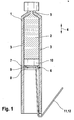
- FIG. 1 shows a container with a drive device according to the invention.
- the container 1 is an ampoule containing a liquid product 2 (for example insulin).
- the container 1 has limiting side walls 3, which extend in the longitudinal direction 4 to an outlet 5 for the liquid product 2 out.
- a displaceable piston 10 is arranged in the container 1.
- the drive device 6 according to the invention has a first segment 7, a second segment 8 and a connecting segment 9.
- the connecting segment 9 has an actively variable length (connecting length), this length determining the distance of the two segments 7, 8 from one another.
- the piston 10 separates the drive device 6 from the liquid product 2 and is firmly connected to the first segment 7 of the drive device 6, so that the segment 7 can actively change its shape, but always bears directly on the piston 10. In the rest position, the drive device 6 is clamped (at least one segment) in the container 1 between the side walls, thus keeping the piston 10 in its position.
- Figures 2a and 2b show an embodiment of a first segment of a drive device according to the invention.
- the first segment 7 is designed as an open ring 13 with two tongues 14 projecting into the ring 13, a first actuator 15 being arranged between the two tongues 14, for example a paraffin actuator.
- the thickness of the actuator 15 is actively changeable, for example by heating and cooling of the actuator 15.
- the first segment 7 shown in FIG. 2a shows the actuator 15 when it is deactivated 16.
- the segment 7 is in its rest position with a first smaller ring diameter. With this smaller ring diameter, the segment 7 would be released from the side walls of a surrounding container and slidable in this.
- the first segment 7 of the drive device according to the invention has an actively variable form. By activating the actuator 15 such a change in shape is achieved.
- the first segment 7 shown in FIG. 2b shows the actuator 15 when it is activated 17.
- the segment 7 is in a spread position with a second larger ring diameter, since the activated actuator 17 by its greater thickness, the tongues 14 presses apart. With this larger ring diameter segment 7 would be clamped between the side walls of a surrounding container and in this largely immovable.
- FIGS. 3a and 3b show an embodiment of a second segment of a drive device according to the invention.
- the second segment 8 is designed as an open ring 13 with two tongues 14 projecting into the ring 13.
- the left-hand tongue 18 and an abutment 19, which is arranged next to the right-hand tongue 20, are connected to a base plate (not shown-lying in the image plane).
- a second actuator 15 is arranged, the thickness of which is actively changeable (for example, by heating or cooling).
- the second segment 8 shown in FIG. 3 a shows the actuator 15 when it is deactivated 16.
- the segment 8 is in its rest position with a first larger one Ring diameter. With the larger ring diameter, the segment 8 would be clamped between the side walls of a surrounding container and in this largely immovable.
- the second segment 8 of the drive device according to the invention has an actively variable form. By activating the actuator 15 such a change in shape is achieved.
- the second segment 8 shown in FIG. 3b shows the actuator 15 when it is activated 17.
- the segment 8 is in a compressed position with a second smaller ring diameter, since the actuator 17, which is supported on the abutment 19, by its extension, the right-hand tongue 20 to the left tongue 18 hindints. With this smaller ring diameter, the segment 8 would be released from the side walls of a surrounding container and slidable in this.
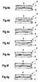
- Figures 4a to 4g show a sequence of movement of a drive device according to the invention.
- the sequence of movements shows how the two segments 7, 8 and the connecting segment 9 cooperate in order to ensure safe advancement of the piston (not shown) in the container (not shown).
- the movement sequence is shown in 6 steps, after the sixth step (Figure 4f) again the first step ( Figure 4g) follows.
- Step 1 represents the rest position of the drive device 6. All three actuators associated with the first segment 7, the connection segment 9 and the second segment 8 are inactive. In the inactive case, the first segment 7 is small, the connecting segment 9 is short and the second segment 8 is large. By activating the respective actuator, the first segment 7 becomes large, the connecting segment 9 long or the second segment 8 small.
- the state (active or inactive) of the respective actuator in the various movement steps 1 to 6 (FIGS.
- step 1 (FIG. 4 a) the second segment 8 is clamped and the first segment 7 is released.
- step 2 Figure 4b
- step 3 Figure 4c
- step 4 Figure 4d
- step 5 Figure 4e
- step 6 both segments 7, 8 are clamped.
- the drive device for the piston of a container (ampoule) of the two segments 7, 8, which are connected to each other via an actuator as a connecting element 9.
- the lower segment contains an outer clamping ring which clamps the segment against the inner wall of the ampoule. This jamming is achieved by compressing the clamping ring with another actuator.
- the upper segment 7 also contains an outer, but normally relaxed clamping ring, which can be clamped with an actuator against the inner wall of the ampoule. At the beginning of a movement of the actuator of the lower segment is relaxed, thus fixing the lower segment relative to the ampoule.
- the actuator of the upper segment is also relaxed and thus the upper segment is movable relative to the ampule.
- the actuator 9, which connects the two segments, is activated.
- the upper segment moves upward and takes the piston of the ampoule with. If the movement is over, the actuator is activated on the clamping ring of the upper segment 7 and the segment 7 is clamped against the wall of the ampoule. Thereafter, the actuator is activated on the clamping ring of the lower segment 8 and solved the deadlock.
- the actuator 9 between the two segments 7, 8 is deactivated and thus the lower segment 8 is tightened.
- the actuator on the clamping ring of the lower segment 8 is deactivated.
- the lower segment 8 jammed again against the wall of the ampoule.
- the actuator on the clamping ring of the upper segment 7 is also deactivated. This completes one motion cycle and all actuators are disabled. Through a variety of such cycles, the ampoule can be emptied in a controlled manner.
- the actuator of the lower segment 8 is activated, the actuator of the upper segment 7 remains deactivated. As a result, the jamming is completely eliminated and the drive can be pulled out of the ampoule on connecting cables or a safety wire.
Landscapes
- Health & Medical Sciences (AREA)
- Hematology (AREA)
- Animal Behavior & Ethology (AREA)
- Vascular Medicine (AREA)
- Engineering & Computer Science (AREA)
- Anesthesiology (AREA)
- Biomedical Technology (AREA)
- Heart & Thoracic Surgery (AREA)
- Physics & Mathematics (AREA)
- Fluid Mechanics (AREA)
- General Health & Medical Sciences (AREA)
- Life Sciences & Earth Sciences (AREA)
- Public Health (AREA)
- Veterinary Medicine (AREA)
- Infusion, Injection, And Reservoir Apparatuses (AREA)
- External Artificial Organs (AREA)
- Closures For Containers (AREA)
- Containers And Packaging Bodies Having A Special Means To Remove Contents (AREA)
Abstract
Description
- Die Erfindung bezieht sich auf eine Antriebsvorrichtung, die einen Kolben in einem Behältnis antreibt, wobei das Behältnis ein flüssiges Produkt enthält, das durch den Kolben über einen Auslass aus dem Behältnis herausgetrieben wird. Solche Antriebsvorrichtungen können insbesondere zur Dosierung eines injizierbaren flüssigen Produkts (zum Beispiel Insulin) in einem Infusionssystem Verwendung finden.
- Die kontinuierliche Infusion von Medikamenten beziehungsweise die diskontinuierliche, gesteuerte Infusion, wie sie zum Beispiel bei der Verabreichung von Insulin notwendig ist, erfolgt in der Regel über sogenannte Spritzenpumpen. Dabei wird der Kolben einer Spritze durch einen geeigneten Stempel kontinuierlich oder diskontinuierlich nach vorne geschoben und ein Medikament dem Patienten über eine Schlauchverbindung und eine Injektionskanüle verabreicht.
- Bei Patienten mit Diabetes bedeutet die Verwendung einer Pumpe zur Applikation von Insulin eine wesentliche Erleichterung im täglichen Umgang mit ihrer Krankheit. Dabei ist eine wichtige Anforderung an eine solche Insulinpumpe eine möglichst geringe Größe und damit verbunden ein möglichst geringes Gewicht. Präzision, Zuverlässigkeit und einfache Bedienung werden gemeinhin vorausgesetzt.
- Nachteilig an Pumpen gemäß dem Stand der Technik sind häufig ihre Größe, ihr Gewicht und ihre hohen Herstellkosten, bedingt durch die aufwendige Antriebsmechanik.
- Aus der
WO 01/72358 A1 -
US 6,723,072 B2 bezieht sich auf eine Vorrichtung zum Verabreichen eines flüssigen Medikaments mit einer Kolbenanordnung, die ein Formgedächtniselement enthält, das zwischen zwei Segmenten angeordnet ist und das seine Länge ändern kann. Durch ein abwechselndes Verlängern und Verkürzen des Formgedächtniselements wird dabei eine longitudinale Bewegung der Kolbenanordnung hervorgerufen, da die zwei Segmente im Wesentlichen nur in einer Richtung verschiebbar sind. Dabei wird nicht deutlich, wodurch eine Bewegung der Segmente in die andere Richtung verhindert wird. Der erreichbare Druck des Kolbens ist durch diese Ausgestaltung stark limitiert. Bei leichten Variationen im Innendurchmesser der Ampulle kann ein solch einfaches System versagen, da die Differenzen in der Haftreibung zwischen den beiden Segmenten zu Null werden können. - Die Aufgabe der vorliegenden Erfindung ist es, die Nachteile des Standes der Technik zu vermeiden. Insbesondere soll eine Antriebsvorrichtung für einen Kolben bereitgestellt werden, die eine geringe Größe, ein geringes Gewicht und geringe Herstellungskosten aufweist.
- Diese Aufgabe wird erfindungsgemäß gelöst durch eine Antriebsvorrichtung für einen Kolben in einem ein flüssiges Produkt enthaltenden Behältnis, wobei das Behältnis begrenzende Seitenwände aufweist, die sich in Längsrichtung zu einem Auslass für das flüssige Produkt hin erstrecken. Die erfindungsgemäße Antriebsvorrichtung enthält ein erstes, dem Auslass zugewandtes Segment mit einer aktiv veränderbaren Form, das in einer ersten Form zwischen den Seitenwänden des Behältnisses verklemmt ist und in einer zweiten Form von den Seitenwänden weitgehend gelöst ist. Ferner enthält die Antriebsvorrichtung ein zweites, von dem Auslass abgewandtes Segment mit einer aktiv veränderbaren Form, das in einer ersten Form zwischen den Seitenwänden des Behältnisses verklemmt ist und in einer zweiten Form von den Seitenwänden weitgehend gelöst ist. Ein Verbindungssegment ist zwischen dem ersten und dem zweiten Segment angeordnet und verbindet das erste und zweite Segment miteinander. Das Verbindungssegment weist eine aktiv veränderbare Verbindungslänge auf.
- Die erfindungsgemäße Antriebsvorrichtung ist in dem Behältnis angeordnet, in dem sich auch das flüssige Produkt befindet, wobei der Kolben die Antriebsvorrichtung von dem flüssigen Produkt trennt. Ein großer Vorteil der erfindungsgemäßen Lösung liegt in der geringen Größe des Antriebs. Durch die Position des Antriebs im Inneren des Behältnisses wird ein ansonsten nicht nutzbarer Raum verwendet. Durch die besondere Konstruktion entfallen aufwendige Getriebe und Motoren, wodurch Gewicht und Herstellungskosten gespart werden können.
- Der Auslass des Behältnisses kann sich bei der erfindungsgemäßen Antriebsvorrichtung zum Beispiel in den Seitenwänden des Behältnisses befinden oder an seinem Ende senkrecht zu den Seitenwänden angeordnet sein.
- Das erste und das zweite Segment der erfindungsgemäßen Antriebsvorrichtung weisen eine aktiv veränderbare Form auf. Aktiv veränderbar heißt in diesem Zusammenhang, dass die Formänderung durch äußere Eingriffe (zum Beispiel durch Anlegen eines elektrischen Stroms, Wärmezufuhr oder -ableitung etc.) gezielt hervorgerufen und gesteuert wird. Die Formänderung ist dabei reversibel. Die Formänderung ist gegebenenfalls mit einer Volumenänderung des jeweiligen Segments verbunden.
- Wenn das jeweilige erste oder zweite Segment seine erste Form einnimmt, ist es zwischen den Seitenwänden des Behältnisses verklemmt. Dabei besteht zwischen dem Segment und den Seitenwänden vorzugsweise eine Reibkraftverbindung, die ein Verschieben des Segments in dem Behältnis nicht zulässt.
- Wenn das jeweilige erste oder zweite Segment seine zweite Form einnimmt, ist es von den Seitenwänden weitgehend gelöst, so dass es in dem Behälter (insbesondere in Längsrichtung zu dem Auslass des Behältnisses hin) verschiebbar ist.
- Die beiden Segmente sind durch das Verbindungselement miteinander verbunden, das eine aktiv veränderbare Länge aufweist. Somit wird der Abstand zwischen den beiden Segmenten durch eine Längenänderung des Verbindungselements verändert. Die Längenänderung ist reversibel. Aktiv veränderbar heißt in diesem Zusammenhang, dass die Längenänderung durch äußere Eingriffe (zum Beispiel durch Anlegen eines elektrischen Stroms, Wärmezufuhr oder -ableitung etc.) gezielt hervorgerufen und gesteuert wird. Die Längenänderung kann insbesondere mit einer Volumenänderung des Verbindungselements verknüpft sein.
- Mit der erfindungsgemäßen Antriebsvorrichtung wird das flüssige Produkt aus dem Behältnis heraus dosiert, indem die Antriebsvorrichtung den Kolben in dem Behältnis zu dem Auslass hin verschiebt und so das flüssige Produkt durch den Auslass herausdrückt.
- Um ein solches Verschieben des Kolbens zu erreichen, führen die beiden Segmente und das Verbindungssegment den folgenden Bewegungsablauf durch:
- Verklemmen des zweiten Segments zwischen den Seitenwänden durch eine aktive Formänderung des zweiten Segments,
- Lösen des ersten Segments von den Seitenwänden durch eine aktive Formänderung des ersten Segments,
- Vergrößern der Länge des Verbindungssegments, wobei sich das erste Segment in Richtung des Auslasses verschiebt,
- Verklemmen des ersten Segments zwischen den Seitenwänden durch eine aktive Formänderung des ersten Segments,
- Lösen des zweiten Segments von den Seitenwänden durch eine aktive Formänderung des zweiten Segments und
- Verkleinern der Länge des Verbindungssegments, wobei sich das zweite Segment in Richtung des Auslasses verschiebt.
- Das erste Segment hat direkten Kontakt zu dem Kolben und schiebt diesen bei seiner Bewegung auf den Auslass des Behältnisses zu. Vorzugsweise ist das erste Segment mit dem Kolben fest verbunden oder einstückig mit dem Kolben ausgebildet. Dadurch wird zum Beispiel vermieden, dass sich der Kolben ohne die Antriebsvorrichtung bewegt und flüssiges Produkt (zum Beispiel durch einen Unterdruck am Auslass des Behältnisses) ungewollt austreten kann. Die feste (gegebenenfalls lösbare) Verbindung zwischen dem Kolben und dem ersten Segment der erfindungsgemäßen Antriebsvorrichtung kann zum Beispiel durch eine Schnappverbindung, durch eine Magnetkupplung oder mit einem geeigneten Aktuator erfolgen.
- Gemäß einer bevorzugten Ausführungsform der vorliegenden Erfindung umfassen das erste und das zweite Segment erste beziehungsweise zweite Aktuatoren zur aktiven Veränderung der Form des ersten beziehungsweise des zweiten Segments. Ferner ist vorzugsweise auch das Verbindungselement selbst als Aktuator ausgeführt oder es umfasst einen Aktuator, um die Längenänderung des Verbindungselements aktiv zu erreichen. Die Aktuatoren sind dabei ansteuerbar, insbesondere durch Strom oder Wärme, so dass bei der Ansteuerung (Aktivierung) des jeweiligen Aktuators eine Formänderung des jeweiligen Segments beziehungsweise eine Längenänderung des Verbindungselements erfolgt. Der Aktuator weist bei seiner Aktivierung zum Beispiel eine Volumenvergrößerung auf, die beispielsweise durch Wärmedehnung oder eine Phasenänderung hervorgerufen wird, durch die eine Kraft zumindest auf Abschnitte des Segments ausgeübt wird, die ein Verklemmen oder Lösen des Segments von den Seitenwänden des Behältnisses hervorruft. Das gesamte Segment selbst kann in einer Ausführungsform der vorliegenden Erfindung ein Aktuator sein.
- Als Aktuatoren können solche eingesetzt werden, die den räumlichen Anforderungen gerecht werden, unabhängig von dem zugrundeliegenden Prinzip. Denkbar sind elektromagnetische, piezoelektrische, chemische, elektrochemische, thermische oder sonstige Aktuatoren. Ein Beispiel für verwendbare Aktuatoren sind auch die in
US 6,723,072 B2 genannten Formgedächtnislegierungen. Gemäß einer bevorzugten Ausfiihrungsform der vorliegenden Erfindung sind die Aktuatoren Paraffinaktuatoren, wobei die Antriebsvorrichtung Heizelemente zum Erwärmen der Paraffinaktuatoren umfasst. Solche Aktuatoren werden zum Beispiel in Carlen, Mastrangelo: "Simple, high actuation power, thermally activated paraffin microactuator", vorgestellt bei der Transducers 1999 Conference, Sendai, Japan, 7. bis 10. Juni 1999 beschrieben. Die Paraffinaktuatoren weisen zum Beispiel gegenüber den Formgedächtnislegierungen Vorteile auf. Die maximale Längenänderung der Formgedächtnislegierungen beträgt nur 5%. Damit sind größere Bauteile oder aufwendigere Hebelsysteme notwendig, um die notwendigen Aktuationslängen zu erreichen. Diese Längen dürfen einen Mindestbetrag nicht unterschreiten, da die elastische Verformung des Kolbens überschritten werden muss, bevor eine Relativbewegung zwischen Kolben und Behältniswand erfolgt. Paraffinaktuatoren ermöglichen mit einer Volumenexpansion von > 15 % eine höhere lineare Ausdehnung und erlauben somit eine kleinere Bauweise. Durch die Arbeitstemperatur im Bereich von 60 °C sind ferner die thermischen Verluste deutlich kleiner. Die Temperaturen zum Phasenwechsel bei Formgedächtnislegierungen liegen in der Nähe von 100 °C. Dies bedingt einen höheren Wärmeverlust und damit einen geringeren Wirkungsgrad des Antriebs. - Gemäß einer bevorzugten Ausführungsform der vorliegenden Erfindung ist das erste Segment so ausgebildet, dass es bei einem nicht aktivierten ersten Aktuator in der zweiten Form vorliegt und das zweite Segment ist so ausgebildet, dass es bei nicht aktiviertem zweiten Aktuator in der ersten Form vorliegt. Bei inaktivem ersten Aktuator ist das erste Segment also von den Seitenwänden des Behältnisses gelöst, während das zweite Segment bei inaktivem zweiten Aktuator zwischen den Seitenwänden des Behältnisses verklemmt ist. Daher ist der Antrieb, wenn alle Aktuatoren deaktiviert sind und keine Energie verbraucht wird, trotzdem zwischen den Seitenwänden des Behältnisses verklemmt und ohne eine gezielte Aktivierung der Aktuatoren nicht verschiebbar.
- Gemäß einer Ausführungsform der vorliegenden Erfindung ist das Behältnis eine Ampulle mit einem kreisförmigen Querschnitt und die ersten und zweiten Segmente umfassen Spannringe, die mit Hilfe jeweils eines Aktuators zwischen einer inneren Wandung der Ampulle verklemmbar oder von dieser lösbar sind. Dabei weisen die Spannringe vorzugsweise jeweils einen Ringdurchmesser auf, der durch ein Aktivieren der Aktuatoren veränderbar ist. Die Spannringe selbst können Aktuatoren sein, zum Beispiel Bimetallringe, die sich je nach Aufbau bei der Aktivierung öffnen und verengen. In diesem Fall sind keine zusätzlichen Aktuatoren für die Segmente notwendig.
- Gemäß einer bevorzugten Ausfiihrungsform der vorliegenden Erfindung ist das erste Segment als offener Ring mit zwei in den Ring hineinragenden Zungen ausgebildet, wobei zwischen den beiden Zungen ein Aktuator angeordnet ist, dessen Dicke aktiv veränderbar ist. Ferner kann das zweite Segment als offener Ring mit zwei in den Ring hineinragenden Zungen ausgebildet sein, wobei eine der Zungen und ein neben der anderen Zunge angeordnetes Widerlager mit einer Grundplatte verbunden sind und zwischen der anderen Zunge und dem Widerlager ein Aktuator angeordnet ist, dessen Dicke aktiv veränderbar ist. Durch die Befestigung der einen Zunge und des Widerlagers an der Grundplatte wird sichergestellt, dass eine feste räumliche Beziehung zwischen der einen Zunge und dem Widerlager besteht.
- Zur Kontrolle der Position der erfindungsgemäßen Antriebsvorrichtung oder des Kolbens in dem Behältnis kann ein Messsystem, zum Beispiel auf der Basis der Lasertriangulation, eingesetzt werden. Damit ist es möglich, mit Hilfe geeigneter elektronischer Prozessoren die exakte Position des Kolbens in dem Behältnis zu bestimmen. Daraus lässt sich die dosierte Menge an flüssigem Produkt ableiten und die Schrittweite des nächsten Zyklus an die gewünschte Dosierung anpassen.
- Die vorliegende Erfindung hat weiterhin die Verwendung der erfindungsgemäßen Antriebsvorrichtung zum Dosieren eines flüssigen Produkts in einem Infusionssystem zum Gegenstand. Die Antriebsvorrichtung kann insbesondere in einer Pumpe zur Applikation von Insulin aus einer Ampulle eingesetzt werden. Die Anwendung ist aber nicht darauf beschränkt, sondern auch andere Wirkstofflösungen können damit in der Human- oder Tiermedizin appliziert werden, besonders, wenn eine kleine, leichte tragbare Pumpe erforderlich ist. Auch für den Transport von Perfusionsflüssigkeit von kontinuierlicher Mikrodialyse ist die vorliegende Erfindung geeignet. In technischen Systemen kann eine Pumpe mit einer erfindungsgemäßen Antriebsvorrichtung eingesetzt werden, um kleine Mengen zum Beispiel von Schmierstoffen oder Reagenzien in unterschiedlichsten Anwendungen zu dosieren.
- Die Erfindung bezieht sich weiterhin auf ein Verfahren zum Dosieren eines flüssigen Produkts durch Verschieben eines Kolbens in einem das flüssige Produkt enthaltenden Behältnis mit Hilfe einer Antriebsvorrichtung, wobei das Behältnis begrenzende Seitenwände aufweist, die sich in Längsrichtung zu einem Auslass für das flüssige Produkt hin erstrecken und die Antriebsvorrichtung ein erstes, dem Auslass zugewandtes Segment, ein zweites von dem Auslass abgewandtes Segment und ein zwischen den zwei Segmenten angeordnetes und diese miteinander verbindendes Verbindungssegment umfasst, mit den Verfahrensschritten:
- Verklemmen des zweiten Segments zwischen den Seitenwänden durch eine aktive Formänderung des zweiten Segments,
- Lösen des ersten Segments von den Seitenwänden durch eine aktive Formänderung des ersten Segments,
- Vergrößern der Länge des Verbindungssegments, wobei sich das erste Segment in Richtung des Auslasses verschiebt,
- Verklemmen des ersten Segments zwischen den Seitenwänden durch eine aktive Formänderung des ersten Segments,
- Lösen des zweiten Segments von den Seitenwänden durch eine aktive Formänderung des zweiten Segments und
- Verkleinern der Länge des Verbindungssegments, wobei sich das zweite Segment in Richtung des Auslasses verschiebt.
- Dabei werden die Verfahrensschritte in dieser Reihenfolge zyklisch durchgeführt, wobei nach dem letzten Verfahrensschritt der erste folgt. Die Ruheposition der Antriebsvorrichtung ist zum Beispiel nach der Durchführung des zweiten Verfahrensschritts erreicht, wenn das zweite Segment verklemmt ist, das erste Segment gelöst ist und das Verbindungssegment eine kleine Länge aufweist. Durch die in den Verfahrensschritten genannte Bewegungsfolge bewegt sich die Antriebsvorrichtung "raupenartig" auf den Auslass des Behältnisses zu und drückt den Kolben vorwärts und damit das flüssige Produkt aus dem Behältnis durch den Auslass heraus.
- Die Erfindung wird nachstehend anhand der Zeichnung näher erläutert.
- Figur 1
- zeigt eine Ampulle mit einem Kolben, in die eine erfindungsgemäße Antriebsvorrichtung eingesetzt ist,
- Figuren 2a und 2b
- zeigen eine Ausführungsform eines ersten Segments einer erfindungsgemäßen Antriebsvorrichtung,
- Figur 3a und 3b
- zeigen eine Ausführungsform eines zweiten Segments einer erfindungsgemäßen Antriebsvorrichtung und
- Figur 4a bis 4g
- zeigen einen Bewegungsablauf einer erfindungsgemäßen Antriebsvorrichtung.
- Figur 1 zeigt ein Behältnis mit einer erfindungsgemäßen Antriebsvorrichtung.
- Das Behältnis 1 ist eine Ampulle, die ein flüssiges Produkt 2 (zum Beispiel Insulin) enthält. Das Behältnis 1 weist begrenzende Seitenwände 3 auf, die sich in Längsrichtung 4 zu einem Auslass 5 für das flüssige Produkt 2 hin erstrecken. Ein verschiebbarer Kolben 10 ist in dem Behältnis 1 angeordnet. Die erfindungsgemäße Antriebsvorrichtung 6 weist ein erstes Segment 7, ein zweites Segment 8 und ein Verbindungssegment 9 auf. Das Verbindungssegment 9 weist eine aktiv veränderbare Länge auf (Verbindungslänge), wobei diese Länge den Abstand der beiden Segmente 7, 8 voneinander bestimmt. Der Kolben 10 trennt die Antriebsvorrichtung 6 von dem flüssigen Produkt 2 und ist fest mit dem ersten Segment 7 der Antriebsvorrichtung 6 verbunden, so dass das Segment 7 zwar seine Form aktiv verändern kann, jedoch stets direkt an dem Kolben 10 anliegt. In Ruheposition ist die Antriebsvorrichtung 6 (mindestens ein Segment) in dem Behältnis 1 zwischen den Seitenwänden verklemmt und hält so den Kolben 10 in seiner Position. Die Signal- und Energieversorgung 11 der Antriebsvorrichtung 6 erfolgt über das Kabel 12.
- Figuren 2a und 2b zeigen eine Ausführungsform eines ersten Segments einer erfindungsgemäßen Antriebsvorrichtung.
- Das erste Segment 7 ist als offener Ring 13 mit zwei in den Ring 13 hineinragenden Zungen 14 ausgebildet, wobei zwischen den beiden Zungen 14 ein erster Aktuator 15 angeordnet ist, zum Beispiel ein Paraffinaktuator. Die Dicke des Aktuators 15 ist aktiv veränderbar, zum Beispiel durch Erwärmen und Abkühlen des Aktuators 15.
- Das in Figur 2a dargestellte erste Segment 7 zeigt den Aktuator 15, wenn er deaktiviert 16 ist. Das Segment 7 befindet sich in seiner Ruheposition mit einem ersten kleineren Ringdurchmesser. Mit diesem kleineren Ringdurchmesser wäre das Segment 7 von den Seitenwänden eines umgebenden Behältnisses gelöst und in diesem verschiebbar. Das erste Segment 7 der erfindungsgemäßen Antriebsvorrichtung hat eine aktiv veränderbare Form. Durch eine Aktivierung des Aktuators 15 wird eine solche Formänderung erreicht.
- Das in Figur 2b dargestellte erste Segment 7 zeigt den Aktuator 15, wenn er aktiviert 17 ist. Das Segment 7 befindet sich in einer gespreizten Position mit einem zweiten größeren Ringdurchmesser, da der aktivierte Aktuator 17 durch seine größere Dicke die Zungen 14 auseinanderdrückt. Mit diesem größeren Ringdurchmesser wäre das Segment 7 zwischen den Seitenwänden eines umgebenden Behältnisses verklemmt und in diesem weitgehend unverschiebbar.
- Um die Ruheposition (Figur 2a) des ersten Segments 7 wieder zu erreichen, wird der Aktuator 15 wieder deaktiviert.
- Figuren 3a und 3b zeigen eine Ausführungsform eines zweiten Segments einer erfindungsgemäßen Antriebsvorrichtung.
- Das zweite Segment 8 ist als offener Ring 13 mit zwei in den Ring 13 hineinragenden Zungen 14 ausgebildet. Die linke Zunge 18 und ein Widerlager 19, das neben der rechten Zunge 20 angeordnet ist, sind mit einer (nicht dargestellten - in der Bildebene liegenden) Grundplatte verbunden. Zwischen der rechten Zunge 20 und dem Widerlager 19 ist ein zweiter Aktuator 15 angeordnet, dessen Dicke aktiv (zum Beispiel durch Erhitzen oder Abkühlen) veränderbar ist.
- Das in Figur 3a dargestellte zweite Segment 8 zeigt den Aktuator 15, wenn er deaktiviert 16 ist. Das Segment 8 befindet sich in seiner Ruheposition mit einem ersten größeren Ringdurchmesser. Mit dem größeren Ringdurchmesser wäre das Segment 8 zwischen den Seitenwänden eines umgebenden Behältnisses verklemmt und in diesem weitgehend unverschiebbar. Das zweite Segment 8 der erfindungsgemäßen Antriebsvorrichtung hat eine aktiv veränderbare Form. Durch eine Aktivierung des Aktuators 15 wird eine solche Formänderung erreicht.
- Das in Figur 3b dargestellte zweite Segment 8 zeigt den Aktuator 15, wenn er aktiviert 17 ist. Das Segment 8 befindet sich in einer zusammengedrückten Position mit einem zweiten kleineren Ringdurchmesser, da der Aktuator 17, der sich am Widerlager 19 abstützt, durch seine Ausdehnung die rechte Zunge 20 zu der linken Zunge 18 hindrückt. Mit diesem kleineren Ringdurchmesser wäre das Segment 8 von den Seitenwänden eines umgebenden Behältnisses gelöst und in diesem verschiebbar.
- Um die Ruheposition (Figur 3a) des zweiten Segments 8 wieder zu erreichen, wird der Aktuator 15 wieder deaktiviert.
- Figuren 4a bis 4g zeigen einen Bewegungsablauf einer erfindungsgemäßen Antriebsvorrichtung.
- Der Bewegungsablauf zeigt, wie die zwei Segmente 7, 8 und das Verbindungssegment 9 zusammenwirken, um einen sicheren Vorschub des (nicht dargestellten) Kolbens in dem (nicht dargestellten) Behältnis zu gewährleisten. Der Bewegungsablauf ist in 6 Schritten dargestellt, wobei nach dem sechsten Schritt (Figur 4f) wieder der erste Schritt (Figur 4g) folgt.
- Schritt 1 (Figur 4a) stellt die Ruheposition der Antriebsvorrichtung 6 dar. Alle drei Aktuatoren, die dem ersten Segment 7, dem Verbindungssegment 9 und dem zweiten Segment 8 zugeordnet sind, sind inaktiv. Im inaktiven Fall ist das erste Segment 7 klein, das Verbindungssegment 9 kurz und das zweite Segment 8 groß. Durch eine Aktivierung des jeweiligen Aktuators wird das erste Segment 7 groß, das Verbindungssegment 9 lang beziehungsweise das zweite Segment 8 klein. Der Zustand (aktiv oder inaktiv) des jeweiligen Aktuators in den verschiedenen Bewegungsschritten 1 bis 6 (Figuren 4a bis 4f) ist der folgenden Tabelle zu entnehmen:
Bewegungsschritt 1 2 3 4 5 6 (Fig.4a) (Fig.4b) (Fig.4c) (Fig.4d) (Fig.4e) (Fig.4f) Aktuator des ersten Segments I I A A A A Aktuator des Verbindungssegments I A A A I I Aktuator des zweiten Segments I I I A A I - Wenn ein Segment 7, 8 groß ist, ist es zwischen den Seitenwänden eines Behältnisses verklemmt, wenn es klein ist, ist es von den Seitenwänden des Behältnisses gelöst. In Schritt 1 (Fig. 4a) ist das zweite Segment 8 verklemmt und das erste Segment 7 gelöst. In Schritt 2 (Fig. 4b) wird das Verbindungssegment 9 lang und schiebt das erste Segment 7 nach oben. In Schritt 3 (Fig. 4c) sind beide Segmente 7, 8 verklemmt. In Schritt 4 (Fig. 4d) ist das erste Segment 7 verklemmt und das zweite Segment 8 gelöst. In Schritt 5 (Fig. 4e) wird das Verbindungssegment 9 kurz und zieht das zweite Segment 8 nach oben. In Schritt 6 (Fig. 4f) sind beide Segmente 7, 8 verklemmt. Dann folgt mit Schritt 1 (Fig. 4g) wieder die Ruheposition.
- In der in Figuren 4a bis 4g dargestellten Ausführungsform besteht die erfindungsgemäße Antriebsvorrichtung für den Kolben eines Behältnisses (Ampulle) aus den zwei Segmenten 7, 8, die über einen Aktuator als Verbindungselement 9 miteinander verbunden sind. Das untere Segment enthält einen außenliegenden Spannring, der das Segment gegen die innere Wandung- der Ampulle verklemmt. Diese Verklemmung wird durch Zusammendrücken des Spannrings mit einem weiteren Aktuator erreicht. Das obere Segment 7 enthält ebenfalls einen außenliegenden, allerdings im Normalfall entspannten Spannring, der mit einem Aktuator gegen die innere Wandung der Ampulle verklemmt werden kann. Zu Beginn einer Bewegung wird der Aktuator des unteren Segments entspannt und damit das untere Segment gegenüber der Ampulle fixiert. Der Aktuator des oberen Segments ist ebenfalls entspannt und damit ist das obere Segment beweglich gegenüber der Ampulle.
- Der Aktuator 9, der beide Segmente miteinander verbindet, wird aktiviert. Dadurch bewegt sich das obere Segment nach oben und nimmt den Kolben der Ampulle mit. Ist die Bewegung zu Ende, so wird der Aktuator am Spannring des oberen Segments 7 aktiviert und das Segment 7 gegen die Wandung der Ampulle verklemmt. Danach wird der Aktuator am Spannring des unteren Segments 8 aktiviert und die Verklemmung gelöst. Der Aktuator 9 zwischen beiden Segmenten 7, 8 wird deaktiviert und damit wird das untere Segment 8 nachgezogen. Der Aktuator am Spannring des unteren Segments 8 wird deaktiviert. Damit verklemmt sich das untere Segment 8 wieder gegen die Wandung der Ampulle. Der Aktuator am Spannring des oberen Segments 7 wird ebenfalls deaktiviert. Damit ist ein Bewegungszyklus abgeschlossen und alle Aktuatoren sind deaktiviert. Durch eine Vielzahl solcher Zyklen kann die Ampulle in gesteuerter Weise entleert werden.
- Zur Entfernung der Antriebsvorrichtung aus der Ampulle wird der Aktuator des unteren Segments 8 aktiviert, der Aktuator des oberen Segments 7 bleibt deaktiviert. Dadurch ist die Verklemmung vollständig aufgehoben und der Antrieb kann an Verbindungskabeln oder einem Fangdraht aus der Ampulle gezogen werden.
-
- 1
- Behältnis
- 2
- flüssiges Produkt
- 3
- Seitenwände
- 4
- Längsrichtung
- 5
- Auslass
- 6
- Antriebsvorrichtung
- 7
- erstes Segment
- 8
- zweites Segment
- 9
- Verbindungssegment
- 10
- Kolben
- 11
- Signal- und Energieversorgung
- 12
- Kabel
- 13
- offener Ring
- 14
- Zungen
- 15
- Aktuator
- 16
- deaktivierter Aktuator
- 17
- aktivierter Aktuator
- 18
- linke Zunge
- 19
- Widerlager
- 20
- rechte Zunge
Claims (11)
- Antriebsvorrichtung für einen Kolben (10) in einem ein flüssiges Produkt (2) enthaltenden Behältnis (1), wobei das Behältnis (1) begrenzende Seitenwände (3) aufweist, die sich in Längsrichtung (4) zu einem Auslass (5) für das flüssige Produkt (2) hin erstrecken, gekennzeichnet durch• ein erstes, dem Auslass (5) zugewandtes Segment (7) mit einer aktiv veränderbaren Form, das in einer ersten Form zwischen den Seitenwänden (3) des Behältnisses (1) verklemmt ist und in einer zweiten Form von den Seitenwänden (3) weitgehend gelöst ist,• ein zweites, von dem Auslass (5) abgewandtes Segment (8) mit einer aktiv veränderbaren Form, das in einer ersten Form zwischen den Seitenwänden (3) des Behältnisses (1) verklemmt ist und in einer zweiten Form von den Seitenwänden (3) weitgehend gelöst ist und• ein Verbindungssegment (9), das zwischen dem ersten (7) und dem zweiten (8) Segment angeordnet ist und das erste (7) und zweite (8) Segment miteinander verbindet, wobei das Verbindungssegment (9) eine aktiv veränderbare Verbindungslänge aufweist.
- Antriebsvorrichtung gemäß Anspruch 1, dadurch gekennzeichnet, dass das erste Segment (7) mit dem Kolben (10) fest verbunden ist oder einstückig mit dem Kolben (10) ausgebildet ist.
- Antriebsvorrichtung gemäß einem der Ansprüche 1 oder 2, dadurch gekennzeichnet, dass das erste und das zweite Segment (7, 8) erste und zweite Aktuatoren (15) zur aktiven Veränderung der Form des ersten beziehungsweise des zweiten Segments (7, 8) umfassen.
- Antriebsvorrichtung gemäß Anspruch 3, dadurch gekennzeichnet, dass die Aktuatoren Paraffinaktuatoren sind und die Antriebsvorrichtung Heizelemente zum Erwärmen der Paraffinaktuatoren umfasst.
- Antriebsvorrichtung gemäß einem der Ansprüche 3 oder 4, dadurch gekennzeichnet, dass das erste Segment (7) so ausgebildet ist, dass es bei inaktivem erstem Aktuator in der zweiten Form vorliegt und dass das zweite Segment (8) so ausgebildet ist, dass es bei inaktivem zweiten Aktuator in der ersten Form vorliegt.
- Antriebsvorrichtung gemäß einem der Ansprüche 1 bis 5, dadurch gekennzeichnet, dass das Behältnis (1) eine Ampulle mit kreisförmigem Querschnitt ist und die ersten und zweiten Segmente (7, 8) Spannringe umfassen, die mit Hilfe jeweils eines Aktuators (15) zwischen einer inneren Wandung der Ampulle verklemmbar oder von dieser lösbar sind.
- Antriebsvorrichtung gemäß Anspruch 6, dadurch gekennzeichnet, dass die Spannringe jeweils einen Ringdurchmesser aufweisen, der durch ein Aktivieren der Aktuatoren (15) veränderbar ist.
- Antriebsvorrichtung gemäß einem der Ansprüche 1 bis 7, dadurch gekennzeichnet, dass das erste Segment (7) als offener Ring (13) mit zwei in den Ring (13) hineinragenden Zungen (14) ausgebildet ist, wobei zwischen den beiden Zungen (14) ein Aktuator (15) angeordnet ist, dessen Dicke aktiv veränderbar ist.
- Antriebsvorrichtung gemäß einem der Ansprüche 1 bis 8, dadurch gekennzeichnet, dass das zweite Segment (8) als offener Ring (13) mit zwei in den Ring (13) hineinragenden Zungen (14, 18, 20) ausgebildet ist, wobei eine der Zungen (18) und ein neben der anderen Zunge (20) angeordnetes Widerlager (19) mit einer Grundplatte verbunden sind und zwischen der anderen Zunge (20) und dem Widerlager (19) ein Aktuator (15) angeordnet ist, dessen Dicke aktiv veränderbar ist.
- Verfahren zum Dosieren eines flüssigen Produktes durch Verschieben eines Kolbens in einem das flüssige Produkt enthaltenden Behältnis mit Hilfe einer Antriebsvorrichtung, wobei das Behältnis begrenzende Seitenwände aufweist, die sich in Längsrichtung zu einem Auslass für das flüssige Produkt hin erstrecken und die Antriebsvorrichtung ein erstes, dem Auslass zugewandtes Segment, ein zweites, von dem Auslass abgewandtes Segment und ein zwischen den zwei Segmenten angeordnetes und diese miteinander verbindendes Verbindungssegment umfasst, gekennzeichnet durch• Verklemmen des zweiten Segments zwischen den Seitenwänden durch eine aktive Formänderung des zweiten Segments,• Lösen des ersten Segments von den Seitenwänden durch eine aktive Formänderung des ersten Segments,• Vergrößern der Länge des Verbindungssegments, wobei sich das erste Segment in Richtung des Auslasses verschiebt,• Verklemmen des ersten Segments zwischen den Seitenwänden durch eine aktive Formänderung des ersten Segments,• Lösen des zweiten Segments von den Seitenwänden durch eine aktive Formänderung des zweiten Segments und• Verkleinern der Länge des Verbindungssegments, wobei sich das zweite. Segment in Richtung des Auslasses verschiebt.
- Verwendung einer Antriebsvorrichtung gemäß einem der Ansprüche 1 bis 9 zum Dosieren eines flüssigen Produkts in einem Infusionssystem.
Priority Applications (4)
| Application Number | Priority Date | Filing Date | Title |
|---|---|---|---|
| EP05021508A EP1769814B1 (de) | 2005-09-30 | 2005-09-30 | Antriebsvorrichtung für einen Kolben in einem ein flüssiges Produkt enthaltenden Behältnis |
| AT05021508T ATE392224T1 (de) | 2005-09-30 | 2005-09-30 | Antriebsvorrichtung für einen kolben in einem ein flüssiges produkt enthaltenden behältnis |
| DE502005003762T DE502005003762D1 (de) | 2005-09-30 | 2005-09-30 | Antriebsvorrichtung für einen Kolben in einem ein flüssiges Produkt enthaltenden Behältnis |
| US11/521,239 US7922694B2 (en) | 2005-09-30 | 2006-09-14 | Drive device for a piston in a container containing a liquid product |
Applications Claiming Priority (1)
| Application Number | Priority Date | Filing Date | Title |
|---|---|---|---|
| EP05021508A EP1769814B1 (de) | 2005-09-30 | 2005-09-30 | Antriebsvorrichtung für einen Kolben in einem ein flüssiges Produkt enthaltenden Behältnis |
Publications (2)
| Publication Number | Publication Date |
|---|---|
| EP1769814A1 true EP1769814A1 (de) | 2007-04-04 |
| EP1769814B1 EP1769814B1 (de) | 2008-04-16 |
Family
ID=35734908
Family Applications (1)
| Application Number | Title | Priority Date | Filing Date |
|---|---|---|---|
| EP05021508A Expired - Lifetime EP1769814B1 (de) | 2005-09-30 | 2005-09-30 | Antriebsvorrichtung für einen Kolben in einem ein flüssiges Produkt enthaltenden Behältnis |
Country Status (4)
| Country | Link |
|---|---|
| US (1) | US7922694B2 (de) |
| EP (1) | EP1769814B1 (de) |
| AT (1) | ATE392224T1 (de) |
| DE (1) | DE502005003762D1 (de) |
Cited By (1)
| Publication number | Priority date | Publication date | Assignee | Title |
|---|---|---|---|---|
| WO2009118553A1 (en) * | 2008-03-27 | 2009-10-01 | The Technology Partnership Plc | Dispensing system |
Families Citing this family (2)
| Publication number | Priority date | Publication date | Assignee | Title |
|---|---|---|---|---|
| CN104394913B (zh) * | 2012-06-27 | 2017-06-16 | 赛诺菲-安万特德国有限公司 | 药物输送装置 |
| CN106714871A (zh) * | 2014-06-25 | 2017-05-24 | 魏民 | 用于给药的输液装置 |
Citations (3)
| Publication number | Priority date | Publication date | Assignee | Title |
|---|---|---|---|---|
| US5222362A (en) * | 1989-01-10 | 1993-06-29 | Maus Daryl D | Heat-activated drug delivery system and thermal actuators therefor |
| WO2001072358A1 (de) * | 2000-03-27 | 2001-10-04 | Disetronic Licensing Ag | Antriebsvorrichtung für einen kolben in einem ein injizierbares produkt enthaltenden behältnis |
| WO2003103763A1 (en) * | 2002-06-06 | 2003-12-18 | Insulet Corporation | Plunger assembly for patient infusion device |
Family Cites Families (1)
| Publication number | Priority date | Publication date | Assignee | Title |
|---|---|---|---|---|
| US6723072B2 (en) | 2002-06-06 | 2004-04-20 | Insulet Corporation | Plunger assembly for patient infusion device |
-
2005
- 2005-09-30 EP EP05021508A patent/EP1769814B1/de not_active Expired - Lifetime
- 2005-09-30 AT AT05021508T patent/ATE392224T1/de not_active IP Right Cessation
- 2005-09-30 DE DE502005003762T patent/DE502005003762D1/de not_active Expired - Lifetime
-
2006
- 2006-09-14 US US11/521,239 patent/US7922694B2/en not_active Expired - Fee Related
Patent Citations (3)
| Publication number | Priority date | Publication date | Assignee | Title |
|---|---|---|---|---|
| US5222362A (en) * | 1989-01-10 | 1993-06-29 | Maus Daryl D | Heat-activated drug delivery system and thermal actuators therefor |
| WO2001072358A1 (de) * | 2000-03-27 | 2001-10-04 | Disetronic Licensing Ag | Antriebsvorrichtung für einen kolben in einem ein injizierbares produkt enthaltenden behältnis |
| WO2003103763A1 (en) * | 2002-06-06 | 2003-12-18 | Insulet Corporation | Plunger assembly for patient infusion device |
Cited By (1)
| Publication number | Priority date | Publication date | Assignee | Title |
|---|---|---|---|---|
| WO2009118553A1 (en) * | 2008-03-27 | 2009-10-01 | The Technology Partnership Plc | Dispensing system |
Also Published As
| Publication number | Publication date |
|---|---|
| DE502005003762D1 (de) | 2008-05-29 |
| US7922694B2 (en) | 2011-04-12 |
| EP1769814B1 (de) | 2008-04-16 |
| US20070093751A1 (en) | 2007-04-26 |
| ATE392224T1 (de) | 2008-05-15 |
Similar Documents
| Publication | Publication Date | Title |
|---|---|---|
| DE19717107B4 (de) | System aus Behältnis und Antriebsvorrichtung für einen Kolben, der in dem ein Medikamentfluid enthaltenden Behältnis gehalten ist | |
| EP3468642B1 (de) | Dosiergerät und injektionsvorrichtung | |
| EP3142728B1 (de) | Dosiervorrichtung für die abgabe von medikamentenfluid aus einem reservoir mit spindelstange zur verschiebung des kolbens | |
| DE60309487T2 (de) | Flussbeschränker mit sicherheitsmerkmal | |
| DE102005008280B3 (de) | Verabreichungsvorrichtung mit Anzeigetrommel | |
| EP1519766B1 (de) | Produktausschüttvorrichtung mit kolbenstangen-eilrücksetzung | |
| EP1704883B1 (de) | Vorrichtung für die dosierte Verabreichung eines fluiden Produkts | |
| DE60025203T2 (de) | Injektionsvorrichtung | |
| DE202004006611U1 (de) | Injektionsgerät zur Verabreichung eines injizierbaren Produkts mit gesicherter Dosiereinrichtung | |
| EP2039382B1 (de) | Ampulle mit Dichtung in zwei Kompressionszuständen | |
| WO2020074988A1 (de) | Einstechvorrichtung für eine verabreichungsvorrichtung | |
| EP3468639B1 (de) | Vorrichtung zur abgabe eines fluids | |
| EP1754498A1 (de) | Antriebsvorrichtung für eine Injektions- oder Infusionsvorrichtung | |
| DE20016779U1 (de) | Wiederverwendbare medizinische Abgabevorrichtung | |
| DE10163328A1 (de) | Verabreichungsgerät mit Verdrehsicherung | |
| EP1523356B1 (de) | Verabreichungsgerät mit rückzugsgesperrter kolbenstange | |
| EP3416891B1 (de) | Anlage zur herstellung einer medizinischen zubereitung | |
| EP3788946B1 (de) | Vorrichtung zur wärmeableitung und verwendung einer solchen vorrichtung | |
| EP2535071B1 (de) | Medikationsvorrichtung zur dosierten Abgabe eines fluiden Mediums | |
| DE10129584B4 (de) | Auslöseeinrichtung für einen Druckstrahlinjektor | |
| EP1769814B1 (de) | Antriebsvorrichtung für einen Kolben in einem ein flüssiges Produkt enthaltenden Behältnis | |
| EP1890750B1 (de) | Längenausgleich für eine einstellvorrichtung einer injektionsvorrichtung | |
| EP3630225B1 (de) | Infusionspumpe mit einem verschiedene betriebszustände einnehmbaren pumpmodul | |
| EP1980283A1 (de) | Medikamentenreservoir und Vorrichtung zur automatisierten Abgabe eines flüssigen Medikaments | |
| DE60202745T2 (de) | Flüssigkeitsinfusionsvorrichtung für Langzeitanwendung |
Legal Events
| Date | Code | Title | Description |
|---|---|---|---|
| PUAI | Public reference made under article 153(3) epc to a published international application that has entered the european phase |
Free format text: ORIGINAL CODE: 0009012 |
|
| AK | Designated contracting states |
Kind code of ref document: A1 Designated state(s): AT BE BG CH CY CZ DE DK EE ES FI FR GB GR HU IE IS IT LI LT LU LV MC NL PL PT RO SE SI SK TR |
|
| AX | Request for extension of the european patent |
Extension state: AL BA HR MK YU |
|
| 17P | Request for examination filed |
Effective date: 20070622 |
|
| GRAP | Despatch of communication of intention to grant a patent |
Free format text: ORIGINAL CODE: EPIDOSNIGR1 |
|
| AKX | Designation fees paid |
Designated state(s): AT BE BG CH CY CZ DE DK EE ES FI FR GB GR HU IE IS IT LI LT LU LV MC NL PL PT RO SE SI SK TR |
|
| GRAS | Grant fee paid |
Free format text: ORIGINAL CODE: EPIDOSNIGR3 |
|
| GRAA | (expected) grant |
Free format text: ORIGINAL CODE: 0009210 |
|
| AK | Designated contracting states |
Kind code of ref document: B1 Designated state(s): AT BE BG CH CY CZ DE DK EE ES FI FR GB GR HU IE IS IT LI LT LU LV MC NL PL PT RO SE SI SK TR |
|
| REG | Reference to a national code |
Ref country code: CH Ref legal event code: EP |
|
| REG | Reference to a national code |
Ref country code: IE Ref legal event code: FG4D Free format text: LANGUAGE OF EP DOCUMENT: GERMAN |
|
| REF | Corresponds to: |
Ref document number: 502005003762 Country of ref document: DE Date of ref document: 20080529 Kind code of ref document: P |
|
| PG25 | Lapsed in a contracting state [announced via postgrant information from national office to epo] |
Ref country code: SI Free format text: LAPSE BECAUSE OF FAILURE TO SUBMIT A TRANSLATION OF THE DESCRIPTION OR TO PAY THE FEE WITHIN THE PRESCRIBED TIME-LIMIT Effective date: 20080416 |
|
| NLV1 | Nl: lapsed or annulled due to failure to fulfill the requirements of art. 29p and 29m of the patents act | ||
| PG25 | Lapsed in a contracting state [announced via postgrant information from national office to epo] |
Ref country code: BG Free format text: LAPSE BECAUSE OF FAILURE TO SUBMIT A TRANSLATION OF THE DESCRIPTION OR TO PAY THE FEE WITHIN THE PRESCRIBED TIME-LIMIT Effective date: 20080716 Ref country code: ES Free format text: LAPSE BECAUSE OF FAILURE TO SUBMIT A TRANSLATION OF THE DESCRIPTION OR TO PAY THE FEE WITHIN THE PRESCRIBED TIME-LIMIT Effective date: 20080727 Ref country code: FI Free format text: LAPSE BECAUSE OF FAILURE TO SUBMIT A TRANSLATION OF THE DESCRIPTION OR TO PAY THE FEE WITHIN THE PRESCRIBED TIME-LIMIT Effective date: 20080416 Ref country code: NL Free format text: LAPSE BECAUSE OF FAILURE TO SUBMIT A TRANSLATION OF THE DESCRIPTION OR TO PAY THE FEE WITHIN THE PRESCRIBED TIME-LIMIT Effective date: 20080416 Ref country code: PT Free format text: LAPSE BECAUSE OF FAILURE TO SUBMIT A TRANSLATION OF THE DESCRIPTION OR TO PAY THE FEE WITHIN THE PRESCRIBED TIME-LIMIT Effective date: 20080917 |
|
| PG25 | Lapsed in a contracting state [announced via postgrant information from national office to epo] |
Ref country code: PL Free format text: LAPSE BECAUSE OF FAILURE TO SUBMIT A TRANSLATION OF THE DESCRIPTION OR TO PAY THE FEE WITHIN THE PRESCRIBED TIME-LIMIT Effective date: 20080416 Ref country code: LV Free format text: LAPSE BECAUSE OF FAILURE TO SUBMIT A TRANSLATION OF THE DESCRIPTION OR TO PAY THE FEE WITHIN THE PRESCRIBED TIME-LIMIT Effective date: 20080416 |
|
| REG | Reference to a national code |
Ref country code: IE Ref legal event code: FD4D |
|
| PG25 | Lapsed in a contracting state [announced via postgrant information from national office to epo] |
Ref country code: IS Free format text: LAPSE BECAUSE OF FAILURE TO SUBMIT A TRANSLATION OF THE DESCRIPTION OR TO PAY THE FEE WITHIN THE PRESCRIBED TIME-LIMIT Effective date: 20080816 |
|
| PG25 | Lapsed in a contracting state [announced via postgrant information from national office to epo] |
Ref country code: LT Free format text: LAPSE BECAUSE OF FAILURE TO SUBMIT A TRANSLATION OF THE DESCRIPTION OR TO PAY THE FEE WITHIN THE PRESCRIBED TIME-LIMIT Effective date: 20080416 Ref country code: DK Free format text: LAPSE BECAUSE OF FAILURE TO SUBMIT A TRANSLATION OF THE DESCRIPTION OR TO PAY THE FEE WITHIN THE PRESCRIBED TIME-LIMIT Effective date: 20080416 Ref country code: IE Free format text: LAPSE BECAUSE OF FAILURE TO SUBMIT A TRANSLATION OF THE DESCRIPTION OR TO PAY THE FEE WITHIN THE PRESCRIBED TIME-LIMIT Effective date: 20080416 Ref country code: CZ Free format text: LAPSE BECAUSE OF FAILURE TO SUBMIT A TRANSLATION OF THE DESCRIPTION OR TO PAY THE FEE WITHIN THE PRESCRIBED TIME-LIMIT Effective date: 20080416 Ref country code: SE Free format text: LAPSE BECAUSE OF FAILURE TO SUBMIT A TRANSLATION OF THE DESCRIPTION OR TO PAY THE FEE WITHIN THE PRESCRIBED TIME-LIMIT Effective date: 20080716 |
|
| PLBE | No opposition filed within time limit |
Free format text: ORIGINAL CODE: 0009261 |
|
| STAA | Information on the status of an ep patent application or granted ep patent |
Free format text: STATUS: NO OPPOSITION FILED WITHIN TIME LIMIT |
|
| EN | Fr: translation not filed | ||
| PG25 | Lapsed in a contracting state [announced via postgrant information from national office to epo] |
Ref country code: SK Free format text: LAPSE BECAUSE OF FAILURE TO SUBMIT A TRANSLATION OF THE DESCRIPTION OR TO PAY THE FEE WITHIN THE PRESCRIBED TIME-LIMIT Effective date: 20080416 Ref country code: RO Free format text: LAPSE BECAUSE OF FAILURE TO SUBMIT A TRANSLATION OF THE DESCRIPTION OR TO PAY THE FEE WITHIN THE PRESCRIBED TIME-LIMIT Effective date: 20080416 |
|
| 26N | No opposition filed |
Effective date: 20090119 |
|
| BERE | Be: lapsed |
Owner name: F. HOFFMANN-LA ROCHE A.G. Effective date: 20080930 Owner name: ROCHE DIAGNOSTICS G.M.B.H. Effective date: 20080930 |
|
| PG25 | Lapsed in a contracting state [announced via postgrant information from national office to epo] |
Ref country code: EE Free format text: LAPSE BECAUSE OF FAILURE TO SUBMIT A TRANSLATION OF THE DESCRIPTION OR TO PAY THE FEE WITHIN THE PRESCRIBED TIME-LIMIT Effective date: 20080416 Ref country code: MC Free format text: LAPSE BECAUSE OF NON-PAYMENT OF DUE FEES Effective date: 20080930 |
|
| PG25 | Lapsed in a contracting state [announced via postgrant information from national office to epo] |
Ref country code: BE Free format text: LAPSE BECAUSE OF NON-PAYMENT OF DUE FEES Effective date: 20080930 |
|
| PG25 | Lapsed in a contracting state [announced via postgrant information from national office to epo] |
Ref country code: IT Free format text: LAPSE BECAUSE OF FAILURE TO SUBMIT A TRANSLATION OF THE DESCRIPTION OR TO PAY THE FEE WITHIN THE PRESCRIBED TIME-LIMIT Effective date: 20080416 |
|
| PG25 | Lapsed in a contracting state [announced via postgrant information from national office to epo] |
Ref country code: CY Free format text: LAPSE BECAUSE OF FAILURE TO SUBMIT A TRANSLATION OF THE DESCRIPTION OR TO PAY THE FEE WITHIN THE PRESCRIBED TIME-LIMIT Effective date: 20080416 |
|
| PG25 | Lapsed in a contracting state [announced via postgrant information from national office to epo] |
Ref country code: AT Free format text: LAPSE BECAUSE OF NON-PAYMENT OF DUE FEES Effective date: 20080930 |
|
| REG | Reference to a national code |
Ref country code: CH Ref legal event code: PL |
|
| GBPC | Gb: european patent ceased through non-payment of renewal fee |
Effective date: 20090930 |
|
| PG25 | Lapsed in a contracting state [announced via postgrant information from national office to epo] |
Ref country code: LU Free format text: LAPSE BECAUSE OF NON-PAYMENT OF DUE FEES Effective date: 20080930 Ref country code: HU Free format text: LAPSE BECAUSE OF FAILURE TO SUBMIT A TRANSLATION OF THE DESCRIPTION OR TO PAY THE FEE WITHIN THE PRESCRIBED TIME-LIMIT Effective date: 20081017 |
|
| PG25 | Lapsed in a contracting state [announced via postgrant information from national office to epo] |
Ref country code: TR Free format text: LAPSE BECAUSE OF FAILURE TO SUBMIT A TRANSLATION OF THE DESCRIPTION OR TO PAY THE FEE WITHIN THE PRESCRIBED TIME-LIMIT Effective date: 20080416 |
|
| PG25 | Lapsed in a contracting state [announced via postgrant information from national office to epo] |
Ref country code: LI Free format text: LAPSE BECAUSE OF NON-PAYMENT OF DUE FEES Effective date: 20090930 Ref country code: CH Free format text: LAPSE BECAUSE OF NON-PAYMENT OF DUE FEES Effective date: 20090930 Ref country code: GR Free format text: LAPSE BECAUSE OF FAILURE TO SUBMIT A TRANSLATION OF THE DESCRIPTION OR TO PAY THE FEE WITHIN THE PRESCRIBED TIME-LIMIT Effective date: 20080717 |
|
| PG25 | Lapsed in a contracting state [announced via postgrant information from national office to epo] |
Ref country code: GB Free format text: LAPSE BECAUSE OF NON-PAYMENT OF DUE FEES Effective date: 20090930 |
|
| PGFP | Annual fee paid to national office [announced via postgrant information from national office to epo] |
Ref country code: DE Payment date: 20100930 Year of fee payment: 6 |
|
| PG25 | Lapsed in a contracting state [announced via postgrant information from national office to epo] |
Ref country code: FR Free format text: LAPSE BECAUSE OF FAILURE TO SUBMIT A TRANSLATION OF THE DESCRIPTION OR TO PAY THE FEE WITHIN THE PRESCRIBED TIME-LIMIT Effective date: 20090227 |
|
| PG25 | Lapsed in a contracting state [announced via postgrant information from national office to epo] |
Ref country code: DE Free format text: LAPSE BECAUSE OF NON-PAYMENT OF DUE FEES Effective date: 20130403 |
|
| REG | Reference to a national code |
Ref country code: DE Ref legal event code: R119 Ref document number: 502005003762 Country of ref document: DE Effective date: 20130403 |