EP1769750A1 - Dispositif pour la reconstruction d'un ligament - Google Patents
Dispositif pour la reconstruction d'un ligament Download PDFInfo
- Publication number
- EP1769750A1 EP1769750A1 EP06024109A EP06024109A EP1769750A1 EP 1769750 A1 EP1769750 A1 EP 1769750A1 EP 06024109 A EP06024109 A EP 06024109A EP 06024109 A EP06024109 A EP 06024109A EP 1769750 A1 EP1769750 A1 EP 1769750A1
- Authority
- EP
- European Patent Office
- Prior art keywords
- bone tunnel
- flexible member
- tunnel
- delivery device
- pulling
- Prior art date
- Legal status (The legal status is an assumption and is not a legal conclusion. Google has not performed a legal analysis and makes no representation as to the accuracy of the status listed.)
- Withdrawn
Links
Images


Classifications
-
- A—HUMAN NECESSITIES
- A61—MEDICAL OR VETERINARY SCIENCE; HYGIENE
- A61F—FILTERS IMPLANTABLE INTO BLOOD VESSELS; PROSTHESES; DEVICES PROVIDING PATENCY TO, OR PREVENTING COLLAPSING OF, TUBULAR STRUCTURES OF THE BODY, e.g. STENTS; ORTHOPAEDIC, NURSING OR CONTRACEPTIVE DEVICES; FOMENTATION; TREATMENT OR PROTECTION OF EYES OR EARS; BANDAGES, DRESSINGS OR ABSORBENT PADS; FIRST-AID KITS
- A61F2/00—Filters implantable into blood vessels; Prostheses, i.e. artificial substitutes or replacements for parts of the body; Appliances for connecting them with the body; Devices providing patency to, or preventing collapsing of, tubular structures of the body, e.g. stents
- A61F2/02—Prostheses implantable into the body
- A61F2/08—Muscles; Tendons; Ligaments
- A61F2/0811—Fixation devices for tendons or ligaments
-
- A—HUMAN NECESSITIES
- A61—MEDICAL OR VETERINARY SCIENCE; HYGIENE
- A61F—FILTERS IMPLANTABLE INTO BLOOD VESSELS; PROSTHESES; DEVICES PROVIDING PATENCY TO, OR PREVENTING COLLAPSING OF, TUBULAR STRUCTURES OF THE BODY, e.g. STENTS; ORTHOPAEDIC, NURSING OR CONTRACEPTIVE DEVICES; FOMENTATION; TREATMENT OR PROTECTION OF EYES OR EARS; BANDAGES, DRESSINGS OR ABSORBENT PADS; FIRST-AID KITS
- A61F2/00—Filters implantable into blood vessels; Prostheses, i.e. artificial substitutes or replacements for parts of the body; Appliances for connecting them with the body; Devices providing patency to, or preventing collapsing of, tubular structures of the body, e.g. stents
- A61F2/02—Prostheses implantable into the body
- A61F2/08—Muscles; Tendons; Ligaments
- A61F2/0805—Implements for inserting tendons or ligaments
-
- A—HUMAN NECESSITIES
- A61—MEDICAL OR VETERINARY SCIENCE; HYGIENE
- A61B—DIAGNOSIS; SURGERY; IDENTIFICATION
- A61B17/00—Surgical instruments, devices or methods, e.g. tourniquets
- A61B17/56—Surgical instruments or methods for treatment of bones or joints; Devices specially adapted therefor
- A61B17/58—Surgical instruments or methods for treatment of bones or joints; Devices specially adapted therefor for osteosynthesis, e.g. bone plates, screws, setting implements or the like
- A61B17/68—Internal fixation devices, including fasteners and spinal fixators, even if a part thereof projects from the skin
- A61B17/84—Fasteners therefor or fasteners being internal fixation devices
- A61B17/86—Pins or screws or threaded wires; nuts therefor
- A61B17/864—Pins or screws or threaded wires; nuts therefor hollow, e.g. with socket or cannulated
-
- A—HUMAN NECESSITIES
- A61—MEDICAL OR VETERINARY SCIENCE; HYGIENE
- A61F—FILTERS IMPLANTABLE INTO BLOOD VESSELS; PROSTHESES; DEVICES PROVIDING PATENCY TO, OR PREVENTING COLLAPSING OF, TUBULAR STRUCTURES OF THE BODY, e.g. STENTS; ORTHOPAEDIC, NURSING OR CONTRACEPTIVE DEVICES; FOMENTATION; TREATMENT OR PROTECTION OF EYES OR EARS; BANDAGES, DRESSINGS OR ABSORBENT PADS; FIRST-AID KITS
- A61F2/00—Filters implantable into blood vessels; Prostheses, i.e. artificial substitutes or replacements for parts of the body; Appliances for connecting them with the body; Devices providing patency to, or preventing collapsing of, tubular structures of the body, e.g. stents
- A61F2/02—Prostheses implantable into the body
- A61F2/08—Muscles; Tendons; Ligaments
- A61F2/0811—Fixation devices for tendons or ligaments
- A61F2002/0847—Mode of fixation of anchor to tendon or ligament
- A61F2002/0852—Fixation of a loop or U-turn, e.g. eyelets, anchor having multiple holes
Definitions
- This invention relates to medical devices and procedures in general, and more particularly to medical devices and procedures for reconstructing a ligament.
- a ligament is a piece of fibrous tissue which connects one bone to another.
- Ligaments are frequently damaged (e.g., detached or torn or ruptured, etc.) as the result of injury and/or accident.
- a damaged ligament can impede proper motion of a joint and cause significant pain.
- ACL anterior cruciate ligament
- graft ligament 25 may be positioned in tunnel 20 and secured in position.
- the bone tunnel 20 is formed by drilling through tibia 10 and up into femur 15, whereby to form tibial tunnel 30 and femoral tunnel 35. Then a transverse bone tunnel 40 is formed in femur 15 so that transverse bone tunnel 40 intersects femoral tunnel 35. Bone tunnel 20 bifurcates transverse bone tunnel 40 into two tunnel portions, a first transverse bone tunnel portion 45 and a second transverse bone tunnel portion 50.
- a flexible member 55 is used to draw graft ligament 25 up into place.
- this is done by threading flexible member 55 through transverse bone tunnel 40.
- a crochet-hook device (not shown in Fig. 3) is passed up tibial tunnel 30, across the interior of the knee joint, and up femoral tunnel 35.
- the crochet-hook device is used to hook flexible member 55 at the intersection of transverse bone tunnel 40 and femoral tunnel 35.
- the crochet-hook device is used to pull flexible member 55 down femoral tunnel 35, across the interior of the knee joint, down tibial tunnel 30, and out the front side of tibia 10.
- graft ligament 25 is looped over flexible member 55 (Fig. 3).
- One or both free ends of flexible member 55 is/are then pulled away from femur 15, whereby to pull flexible member 55, and hence the looped graft ligament 25, up tibial tunnel 30, across the interior of the knee joint, and then up into femoral tunnel 35 (Fig. 4).
- the graft ligament may be retained in that position by passing a cannulated crosspin 60 over flexible member 55 and into transverse bone tunnel 40 so that the crosspin 60 extends under graft ligament 25 and supports the looped graft ligament 25 within femoral tunnel 35. Then flexible member 55 is withdrawn from the surgical site.
- flexible member 55 must first be drawn down femoral tunnel 35, across the interior of the knee joint, and then down tibial tunnel 30 in order to pick up graft ligament 25; and then later, flexible member 55 must be drawn back up tibial tunnel 30, across the interior of the knee joint, and then back up femoral tunnel 35 in order to carry graft ligament 25 into position. These actions cause flexible member 55 to engage the bone which is located at the intersection of femoral tunnel 35 and transverse bone tunnel 40, i.e., to engage the bone edges 65 (Fig.
- an object of the present invention is to provide an improved method for reconstructing a ligament.
- Another object of the present invention is to provide an improved method for reconstructing a ligament which substantially avoids various problems associated with the prior art.
- the invention comprises a method for securing a graft ligament in a bone tunnel, the method comprising the steps of: (1) forming a first bone tunnel in a bone, and forming a second bone tunnel in the same bone, the second bone tunnel being transverse to, and intersecting, the first bone tunnel, the second bone tunnel having first and second portions extending from the first bone tunnel; (2) positioning the first and second ends of a flexible member within the first bone tunnel such that the first and second ends are located adjacent to the intersection of the second bone tunnel with the first bone tunnel, and extracting the first and second ends out of the first and second portions of the second bone tunnel, respectively, and positioning the graft ligament over a portion of the flexible member extending out of the first bone tunnel; and (3) pulling the ends of the flexible member so as to draw the graft ligament into the first bone tunnel.
- the invention also comprises apparatus for securing a graft ligament in a bone tunnel, the apparatus comprising a flexible member delivery device having a suture holder for carrying the ends of a flexible member into the bone tunnel and being cannulated for receiving an arthroscope within said cannulated delivery device.
- the invention comprises a system for securing a graft ligament in a bone tunnel, the system comprising a flexible member for positioning the graft ligament in the bone tunnel, a flexible member delivery device having an end for positioning the two ends of the flexible member in the bone tunnel, and a pulling member having an end for withdrawing one end of the flexible member from the delivery device positioned in the bone tunnel and pulling that end of the flexible member through a portion of a second bone tunnel which intersects, and extends transverse to, the first-mentioned bone tunnel.
- the present invention comprises a novel method and apparatus for reconstructing a ligament.
- the bone tunnel 20 is formed by drilling through tibia 10 and up into femur 15, whereby to form tibial tunnel 30 and femoral tunnel 35. Then the transverse bone tunnel 40 is formed in femur 15 so that transverse bone tunnel 40 intersects femoral tunnel 35. Bone tunnel 20 bifurcates transverse bone tunnel 40 into two tunnel portions, a first transverse bone tunnel portion 45 and a second bone tunnel portion 50.
- a flexible member 55 is passed up bone tunnel 20.
- Flexible member 55 has first and second ends 60, 65.
- First and second ends 60, 65 are passed up tibial tunnel 30, across the interior of the knee joint, and up femoral tunnel 35. This may be done by placing first and second ends 60, 65 on the distal end of a delivery device 70, e.g., in the manner shown in Figs. 6-9, and then inserting delivery device 70 (and hence first and second ends 60, 65 of flexible member 55) up tibial tunnel 30, across the interior of the knee joint, and then up femoral tunnel 35. Ends 60, 65 are held to the delivery device 70 in ways which will be discussed in more detail below.
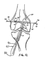
- first and second ends 60, 65 are drawn through transverse bone tunnel portion 45, 50. Where first and second ends include loops 60A, 65A, this may be accomplished by using a hooked-shaped pulling device 75. Pulling device 75 hooks and draws first and second ends 60, 65 through transverse bone tunnel portions 45, 50, respectively. See Figs. 10-12. Alternatively, where first and second ends 60, 65 do not include hooks 60A, 65A, pulling device 75 may include needle-nose pliers or the like at its distal end to pick up and extract first and second ends 60, 65.
- Delivery device 70 is then withdrawn from bone tunnel 20. At this point, the middle portion of flexible member 55 extends out of tibial tunnel 30, as shown generally at 80. See Figs. 10-13.
- graft ligament 25 is looped through flexible member 55 at the middle portion of flexible member 55, as shown generally at 80.
- First and second ends 60, 65 of flexible member 55 are then pulled away from femur 15, in the manner shown in Fig. 13, whereby to pull flexible member 55, and hence graft ligament 25, up tibial tunnel 30, across the interior of the knee joint, and up femoral tunnel 35 so as to achieve the position shown in Fig. 14.
- flexible member 55 is drawn through bone tunnel 20 only once, i.e., at the time that graft ligament 25 is hoisted into position in femoral tunnel 35.
- This is in contrast to the method taught in the aforementioned U.S. Patent No. 5,918,604 , where flexible member 55 is drawn through bone tunnel 20 twice, i.e., once when flexible member 55 is drawn down bone tunnel 20 to pick up graft ligament 25, and then a second time when graft ligament 25 is drawn back up through bone tunnel 20.
- the method of the present invention will cause less bone erosion than the method disclosed in the aforementioned U.S. Patent No. 5,918,604 .
- flexible member 55 is then used as a guide to pass a crosspin 85 through transverse bone tunnel 40 and, in the process, beneath looped graft ligament 25, whereby to support graft ligament 25 within bone tunnel 20. Flexible member 55 may then be removed from transverse bone tunnel 40. The proximal end of the graft may thereafter be secured to tibia 10 in ways well known in the art so as to complete the ligament repair procedure.
- the preferred embodiment of delivery device 70 is cannulated such that an arthroscope 90 may be received therein.
- This configuration aids in visualizing placement of the ends 60, 65 of flexible member 55 in femoral tunnel 35 and in the pick-up and extraction of those ends through transverse bone tunnel portions 45 and 50.
- the schematic diagrams of Figs. 6 and 10-12 show only the first and second ends 60, 65 of flexible member 55, and arthroscope 90, and omit delivery device 70 from the views.
- the ends 60, 65 of flexible member 55 are looped as shown at 60A, 65A.
- Hooks 95 on delivery device 70 carry looped ends 60A, 65A through bone tunnel 20. Looped ends 60A, 65A are then removed from delivery device 70 by hook 100 on pulling device 75, and flexible member 55 is pulled through bone tunnel 40.
- Figs. 7 and 8 show hooks 95 inboard of the outer perimeter of the shaft of delivery device 70.
- Fig. 9 shows an alternative embodiment with two hooks 95 outboard of the outer perimeter of the shaft of delivery device 70.
- ends 60, 65 of flexible member 55 may be without loops.
- delivery device 70, and pulling device 75 may grasp ends 60, 65 with suture grasping devices (not shown) in ways well known in the art, e.g., with opposing jaws.
- suture grasping devices not shown
- one or more grasping device(s) on delivery device 70 retain ends 60, 65 of flexible member 55 until pulling device 75 takes hold of ends 60, 65.
- Pulling device 75 then draws each end 60, 65 through first and second transverse bone tunnels 45, 50, respectively.
- flexible member 55 is less likely to twist when first and second ends 60, 65 are passed up bone tunnel 20 and then out transverse bone tunnel 40.
Applications Claiming Priority (2)
| Application Number | Priority Date | Filing Date | Title |
|---|---|---|---|
| US14800599P | 1999-08-10 | 1999-08-10 | |
| EP00952670A EP1210015B1 (fr) | 1999-08-10 | 2000-08-09 | Dispositif de reconstruction d'un ligament |
Related Parent Applications (1)
| Application Number | Title | Priority Date | Filing Date |
|---|---|---|---|
| EP00952670A Division EP1210015B1 (fr) | 1999-08-10 | 2000-08-09 | Dispositif de reconstruction d'un ligament |
Publications (1)
| Publication Number | Publication Date |
|---|---|
| EP1769750A1 true EP1769750A1 (fr) | 2007-04-04 |
Family
ID=37801534
Family Applications (1)
| Application Number | Title | Priority Date | Filing Date |
|---|---|---|---|
| EP06024109A Withdrawn EP1769750A1 (fr) | 1999-08-10 | 2000-08-09 | Dispositif pour la reconstruction d'un ligament |
Country Status (1)
| Country | Link |
|---|---|
| EP (1) | EP1769750A1 (fr) |
Cited By (1)
| Publication number | Priority date | Publication date | Assignee | Title |
|---|---|---|---|---|
| WO2011128592A1 (fr) * | 2010-04-14 | 2011-10-20 | Pierre Imbert | Systeme ancillaire pour la pose d'un transplant ligamentaire a l'aide de broches. |
Citations (6)
| Publication number | Priority date | Publication date | Assignee | Title |
|---|---|---|---|---|
| US5234435A (en) * | 1991-03-08 | 1993-08-10 | Seagrave Jr Richard A | Surgical method and apparatus |
| US5393302A (en) * | 1992-10-05 | 1995-02-28 | Clark; Ron | Process for endosteal ligament mounting |
| US5674224A (en) * | 1994-11-18 | 1997-10-07 | Howell; Stephen M. | Bone mulch screw assembly for endosteal fixation of soft tissue grafts and method for using same |
| WO1999015095A1 (fr) * | 1997-09-24 | 1999-04-01 | Depuy Orthopaedics, Inc. | Broche de fixation pour ligament croise anterieur et procede d'utilisation associe |
| US5891150A (en) * | 1996-12-04 | 1999-04-06 | Chan; Kwan-Ho | Apparatus and method for fixing a ligament in a bone tunnel |
| EP0931514A2 (fr) * | 1998-01-28 | 1999-07-28 | Ethicon, Inc. | Dispositif pour fixer un greffon dans un canal d'un os |
-
2000
- 2000-08-09 EP EP06024109A patent/EP1769750A1/fr not_active Withdrawn
Patent Citations (6)
| Publication number | Priority date | Publication date | Assignee | Title |
|---|---|---|---|---|
| US5234435A (en) * | 1991-03-08 | 1993-08-10 | Seagrave Jr Richard A | Surgical method and apparatus |
| US5393302A (en) * | 1992-10-05 | 1995-02-28 | Clark; Ron | Process for endosteal ligament mounting |
| US5674224A (en) * | 1994-11-18 | 1997-10-07 | Howell; Stephen M. | Bone mulch screw assembly for endosteal fixation of soft tissue grafts and method for using same |
| US5891150A (en) * | 1996-12-04 | 1999-04-06 | Chan; Kwan-Ho | Apparatus and method for fixing a ligament in a bone tunnel |
| WO1999015095A1 (fr) * | 1997-09-24 | 1999-04-01 | Depuy Orthopaedics, Inc. | Broche de fixation pour ligament croise anterieur et procede d'utilisation associe |
| EP0931514A2 (fr) * | 1998-01-28 | 1999-07-28 | Ethicon, Inc. | Dispositif pour fixer un greffon dans un canal d'un os |
Cited By (2)
| Publication number | Priority date | Publication date | Assignee | Title |
|---|---|---|---|---|
| WO2011128592A1 (fr) * | 2010-04-14 | 2011-10-20 | Pierre Imbert | Systeme ancillaire pour la pose d'un transplant ligamentaire a l'aide de broches. |
| FR2958841A1 (fr) * | 2010-04-14 | 2011-10-21 | Pierre Imbert | Systeme ancillaire pour la pose d'un transplant ligamentaire a l'aide de broches |
Similar Documents
| Publication | Publication Date | Title |
|---|---|---|
| US6610064B1 (en) | Apparatus and method for reconstructing a ligament | |
| US6499486B1 (en) | Method for reconstructing a ligament | |
| US7591850B2 (en) | Surgical methods for anchoring and implanting tissues | |
| US6808528B2 (en) | Apparatus and method for securing a graft ligament in a bone tunnel | |
| EP2327374B1 (fr) | Fixation fémorale | |
| CA2637682C (fr) | Encocheuse de tunnel osseux et dispositif de mise en place de fil-guide | |
| US7066956B2 (en) | Transverse fixation technique for ACL reconstruction using bone-tendon-bone graft | |
| US5603716A (en) | Method of ligament reconstruction using double socket graft placement and fixation | |
| CA2278124C (fr) | Procede et appareil de fixation d'un bloc osseux dans un canal osseux | |
| US20030176919A1 (en) | Transverse fixation technique for ACL reconstruction using bone-tendon-bone graft with loop at end | |
| US10383657B2 (en) | Devices and methods for tissue graft delivery | |
| EP1180351B1 (fr) | Appareil pour reconstruire un ligament | |
| EP1769750A1 (fr) | Dispositif pour la reconstruction d'un ligament | |
| AU2002301618B2 (en) | Transverse fixation technique for acl reconstruction using bone-tendon-bone graft | |
| CN115813518A (zh) | 一种前交叉韧带修补装置及其使用方法 |
Legal Events
| Date | Code | Title | Description |
|---|---|---|---|
| PUAI | Public reference made under article 153(3) epc to a published international application that has entered the european phase |
Free format text: ORIGINAL CODE: 0009012 |
|
| AC | Divisional application: reference to earlier application |
Ref document number: 1210015 Country of ref document: EP Kind code of ref document: P |
|
| AK | Designated contracting states |
Kind code of ref document: A1 Designated state(s): DE FR GB IT |
|
| 17P | Request for examination filed |
Effective date: 20070920 |
|
| 17Q | First examination report despatched |
Effective date: 20071025 |
|
| AKX | Designation fees paid |
Designated state(s): DE FR GB IT |
|
| RAP1 | Party data changed (applicant data changed or rights of an application transferred) |
Owner name: DEPUY MITEK, INC. |
|
| STAA | Information on the status of an ep patent application or granted ep patent |
Free format text: STATUS: THE APPLICATION IS DEEMED TO BE WITHDRAWN |
|
| 18D | Application deemed to be withdrawn |
Effective date: 20090421 |