EP1767928A1 - A measuring device for the shortwavelength x ray diffraction and a method thereof - Google Patents
A measuring device for the shortwavelength x ray diffraction and a method thereof Download PDFInfo
- Publication number
- EP1767928A1 EP1767928A1 EP05759557A EP05759557A EP1767928A1 EP 1767928 A1 EP1767928 A1 EP 1767928A1 EP 05759557 A EP05759557 A EP 05759557A EP 05759557 A EP05759557 A EP 05759557A EP 1767928 A1 EP1767928 A1 EP 1767928A1
- Authority
- EP
- European Patent Office
- Prior art keywords
- goniometer
- detector
- wavelength
- short
- ray
- Prior art date
- Legal status (The legal status is an assumption and is not a legal conclusion. Google has not performed a legal analysis and makes no representation as to the accuracy of the status listed.)
- Withdrawn
Links
Images



Classifications
-
- G—PHYSICS
- G01—MEASURING; TESTING
- G01N—INVESTIGATING OR ANALYSING MATERIALS BY DETERMINING THEIR CHEMICAL OR PHYSICAL PROPERTIES
- G01N23/00—Investigating or analysing materials by the use of wave or particle radiation, e.g. X-rays or neutrons, not covered by groups G01N3/00 – G01N17/00, G01N21/00 or G01N22/00
- G01N23/20—Investigating or analysing materials by the use of wave or particle radiation, e.g. X-rays or neutrons, not covered by groups G01N3/00 – G01N17/00, G01N21/00 or G01N22/00 by using diffraction of the radiation by the materials, e.g. for investigating crystal structure; by using scattering of the radiation by the materials, e.g. for investigating non-crystalline materials; by using reflection of the radiation by the materials
- G01N23/207—Diffractometry using detectors, e.g. using a probe in a central position and one or more displaceable detectors in circumferential positions
-
- G—PHYSICS
- G01—MEASURING; TESTING
- G01N—INVESTIGATING OR ANALYSING MATERIALS BY DETERMINING THEIR CHEMICAL OR PHYSICAL PROPERTIES
- G01N23/00—Investigating or analysing materials by the use of wave or particle radiation, e.g. X-rays or neutrons, not covered by groups G01N3/00 – G01N17/00, G01N21/00 or G01N22/00
- G01N23/20—Investigating or analysing materials by the use of wave or particle radiation, e.g. X-rays or neutrons, not covered by groups G01N3/00 – G01N17/00, G01N21/00 or G01N22/00 by using diffraction of the radiation by the materials, e.g. for investigating crystal structure; by using scattering of the radiation by the materials, e.g. for investigating non-crystalline materials; by using reflection of the radiation by the materials
Definitions
- An object of the invention is to provide a tomoscan device for short-wavelength X-ray diffraction analysis mainly for lower-atomic-number crystalline test samples or work pieces made of Al, Mg, Si, etc., which can increase the measurable depth or thickness in work piece by about 10 times.
- the collimator entrance diaphragm is a round-aperture collimator entrance diaphragm or a rectangular-aperture collimator entrance diaphragm.
- a barrier material for the collimator entrance diaphragm is Pb or a heavy metal that has a stronger X-ray absorption capability than Pb, such as Au. If a single-point radiation detector, such as a scintillation counter, is used to scan and collect a diffraction pattern, the round-aperture collimator entrance diaphragm or rectangular-aperture collimator entrance diaphragm is used as a parallel position-restricting receiving slit, and the parallel position-restricting receiving slit and the radiation detector can be moved in a cooperative manner.
- the detector is packaged by a lead sheet in a thickness greater than 2mm or another heavy metal sheet with a stronger X-ray absorption capability to shield X-rays, leaving only a window over against the receiving slit and a pinhole for leading out electric wires.
- Fig. 6 is a view in direction A of Fig.5;
- Fig. 8 is a top view of Fig.7;
- the receiving slit 5 is a tapered position-restricting receiving slit for shielding scattered X-rays incident to the detector 6 and diffracted rays from any other part of the work piece, i.e., it only permits the diffracted rays from the measured part entering into the detector and shields the remaining rays.
- the energy analyzer 9 is a multi-channel energy analyzer.
- the table 4 can be translated in X, Y, Z three dimensions and rotated around the rotating axis of the goniometer 7 under the control of the computer 10. Signals from the multi-channel energy analyzer 9 are inputted to the computer 10.
- the device and method used in this embodiment are identical to those used in the first embodiment, with the difference in parameter selection: in this embodiment, WK ⁇ radiation is used, the tube voltage is 280KV, the tube current is 3mA, the distance from the center of the goniometer circle to the radiation detector is 220mm ⁇ 1.0, a NaI scintillation counter 6 is connected to the multi-channel energy analyzer 9, the collimator entrance diaphragm is a round-aperture collimator entrance diaphragm in an inner diameter of 2mm ⁇ 0.1 and a length of 120mm ⁇ 0.5 length, a round-aperture collimator entrance diaphragm in an inner diameter of 0.5mm ⁇ 0.1 and a length of 120mm ⁇ 0.5 is used for the position-restricting receiving slit, and the Nal scintillation counter 6 is shielded with an 8mm ⁇ 0.1 thick lead sheet.
Landscapes
- Chemical & Material Sciences (AREA)
- Crystallography & Structural Chemistry (AREA)
- Physics & Mathematics (AREA)
- Health & Medical Sciences (AREA)
- Life Sciences & Earth Sciences (AREA)
- Analytical Chemistry (AREA)
- Biochemistry (AREA)
- General Health & Medical Sciences (AREA)
- General Physics & Mathematics (AREA)
- Immunology (AREA)
- Pathology (AREA)
- Analysing Materials By The Use Of Radiation (AREA)
Abstract
A measuring device for the short-wavelength X-ray diffraction and a method thereof are disclosed in the present invention. The measuring device comprises: an X-ray tube, an incident diaphragm, a table, a goniometer, a detector and an energy analyzer, the said X-ray tube and detector are arranged in the opposite side of the tame, the detector is intended to receive the transmitted diffracted ray. The measuring method comprises: arranging the X-ray tube and the detector in the opposite side of the table, making the detector receiving the transmitted diffracted ray from a detected site, selecting the detecting parameters of the radiation and the diffraction, placing the test object in the center of circle of the goniometer, measuring the diffracting pattern, and then the data are processed by a computer and the phase and the residual stress of any point and its distribution are obtained. With the measuring device and the measuring method above, a diffracting pattern can be obtained quickly and truly.
Description
- The invention relates to X-ray diffraction measurement, especially a short-wavelength X-ray diffraction scan measuring device and the method thereof for test samples or work pieces made of lower-atomic-number crystalline.
- Presently, X-ray diffraction analysis for substances is widely used in many fields. For example, it can be used to measure structure of crystalline substances (e.g., phase analysis), structural changes of crystalline substances (e.g., residual stress measurement), etc. During X-ray diffraction analysis in the prior art, an X-ray tube with a material Cu, Cr, Fe, or Mo as the anode target are often used. However, the characteristic X-ray emitted from such an X-ray tube is of long wavelength and therefore can only achieve a depth of penetration not greater than 10-4m in some materials such as Mg, Al, or Si. As a result, X-ray diffraction analysis is only applicable to the surface of a test sample or work piece made of such a material, up to the present.
- In view of the drawback that the penetration capability of X-ray is not so strong due to a long X-ray wavelength, patent
CN1049496C discloses an "X-Ray Residual Stress Measuring Device and Method"; wherein, the device in that patent employs a X-ray tube emitting a short-wavelength characteristic X-ray and high tube voltage modified based on that of an existing X-ray residual stress measuring device, and the receiving slit is a position-restricting receiving slit. In the X-ray diffraction measuring method disclosed in the patent, short-wavelength characteristic X-rays are employed based on a measuring method for the existing device; the measured part is placed at the center of a goniometer circle, and only the diffracted rays from the measured part is permitted to enter into the radiation detector due to the position-restricting receiving slit, while the diffracted rays and scattered rays from any other part of the work piece are shielded, so that the residual stress at any part in the measured work piece can be measured within the range of penetration depth of the X-rays. By displacing the work piece, the X-ray stress analyzer can measure the residual stress at another part in the work piece; in that way, determination of three-dimensional distribution of residual stress in a work piece made of a material such as beryllium alloy is achieved. In addition, due to the fact that the shorter the X-ray wavelength is and the lower atomic number of the irradiated work piece materials is, the greater the penetration depth of the incident X-ray will be, diffracted rays from different depths and different positions in an even thicker work piece can be detected with such a method. - However, since the X-ray stress analyzer employs an X-ray diffraction back reflection method to collect a diffraction pattern, the X-ray propagates over a longer path in the work piece. Furthermore, the intensity of the emergent ray from the work piece becomes more attenuated as the propagation path length increases, the principle being shown in Fig. 1, in which the intensity of an emergent ray corresponding to an incident X-ray with an intensity I0 after passing through a work piece with a linear absorption coefficient α and a thickness t is I= I0×e -αt. It can be seen from the above formula, the intensity of an emergent X-ray not only depends on the properties of the work piece and the intensity of the incident ray, but also varies with the propagation distance in the work piece; the longer the propagation distance is (i.e., the longer the sum of the propagation path lengths of the incident ray and diffracted ray in the work piece), the more the intensity loss will be, and thereby the lower the intensity of the emergent ray (the intensity of the diffracted ray) will be. A decreased intensity of the diffracted ray will cause a reduced SNR of measurement and thereby an adverse effect on the measurement of X-ray diffraction. As a result, the technique in the above patent cannot take full advantage of the strong penetration capability of a short-wavelength X-ray, resulting in a lower measurable depth inside of a measured work piece.
- An object of the invention is to provide a tomoscan device for short-wavelength X-ray diffraction analysis mainly for lower-atomic-number crystalline test samples or work pieces made of Al, Mg, Si, etc., which can increase the measurable depth or thickness in work piece by about 10 times.
- Another object of the invention is to provide an easy-to-operate and quick short-wavelength X-ray diffraction measuring method in which the above device is used.
- It is common knowledge that the shorter X-ray wavelength is and the lower the atomic number of a radiated work piece substance is, the thicker the penetration of an incident X-ray in the work piece will be. Based on that principle, the invention employs an X-ray diffraction transmission method instead of an X-ray diffraction back reflection method, so as to reduce greatly the path length of an incident ray and diffracted ray in the work piece, and thereby reduces the intensity loss of the diffracted ray in the measured work piece, increases the intensity of the emergent ray, improves the SNR of the signals received by the detector, and improves the sensitivity of the entire diffraction measuring device. Therefore, diffracted X-rays from different depths and different positions in an even thicker work piece can be collected, so as to implement non-destructive X-ray diffraction analysis for the interior of the entire work piece, and obtain three-dimensional distributions of phase, stress, etc.
- An embodiment of the invention provides a short-wavelength X-ray diffraction measuring device, consisting of an X-ray tube, an entrance diaphragm, a table, a receiving slit, a goniometer, a detector, and an energy analyzer; wherein, the X-ray tube and the detector are located at the two sides of the table.
- The receiving slit and detector are fixed to the goniometer and synchronously rotatable around a measured part of a work piece on the table. The measured part is located on a rotating axis of the goniometer. The goniometer is fixed on a platform. The table is fixed to the goniometer or the platform. The X-ray tube is fixed to the goniometer or the platform. The entrance diaphragm is fixed to the goniometer, the platform, or a clamp for the X-ray tube. An exit of the entrance diaphragm is located on or within the circumference of the goniometer. The work piece on the table can be displaced in X, Y, Z three dimensions along with the table, rotated to an angle Ψ around the rotating axis of the goniometer, or moved in X, Y, Z three dimensions and to an angle Ψ in a cooperative manner. In addition, the receiving slit in an embodiment of the invention also serves to permit only diffracted rays from the measured part of the work piece entering into the detector and shield scattered rays and diffracted rays from other parts of the work piece.
- An anode target of the X-ray tube is made of a heavy metal material such as W, Au, or Ag, etc. so that it can emit a short-wavelength characteristic X-ray at 0.01nm-0.07nm wavelength with a strong penetration capability, which can penetrate to a depth at cm or dm level in a metal, non-metal, or ceramic material (e.g., Al, Mg, Si, etc.) with a low atomic number (Z<20). The tube voltage is 120-350KV and the tube current is 2-10mA, adjustable steplessly. The detector is a radiation detector, a position-sensitive detector, or a one-dimensional semiconductor detector array. The entrance diaphragm is a collimator entrance diaphragm. The receiving slit is a parallel position-restricting receiving slit or a tapered position-restricting receiving slit to shield scattered X-rays incident to the detector or diffracted rays from other parts of the work piece. The energy analyzer is a single-channel energy analyzer or a multi-channel energy analyzer, with the output signals input to a computer. The table is controlled by a computer to be displaced in X, Y, Z three dimensions or rotated around the rotating axis of the goniometer.
- The distance from the X-ray tube to the center of the goniometer circle is equal or not equal to the distance from the detector to the center of the goniometer circle, and is adjustable. The distance from the center of the goniometer circle to the radiation detector or position-sensitive detector is 200-800mm. The center of the goniometer circle in an embodiment of the invention is an intersection point between the rotating axis of the goniometer and the rotation plane of the radiation detector or position-sensitive detector. An incident X-ray is in the rotation plane of the radiation detector or position-sensitive detector and passes through the center of the goniometer circle. A part of the work piece at the center of the goniometer circle is right a measured part.
- The collimator entrance diaphragm is a round-aperture collimator entrance diaphragm or a rectangular-aperture collimator entrance diaphragm. A barrier material for the collimator entrance diaphragm is Pb or a heavy metal that has a stronger X-ray absorption capability than Pb, such as Au. If a single-point radiation detector, such as a scintillation counter, is used to scan and collect a diffraction pattern, the round-aperture collimator entrance diaphragm or rectangular-aperture collimator entrance diaphragm is used as a parallel position-restricting receiving slit, and the parallel position-restricting receiving slit and the radiation detector can be moved in a cooperative manner.
- The round-aperture collimator entrance diaphragm is in an inner diameter of 0.1-2mm and a length of 50-200mm. The rectangular-aperture collimator entrance diaphragm is composed of two or more diaphragms, which are parallel to each other in the same direction and the center lines of which coincide with each other. The barrier material for each diaphragm is in a thickness of ≥4mm. The spacing between the diaphragms is 20-200mm. The inner aperture of each diaphragm is of (1-4) × (0.1-0.8) mm. The total thickness of the barrier materials for the entire rectangular-aperture collimator entrance diaphragm is not less than 15mm.
- The detector is packaged by a lead sheet in a thickness greater than 2mm or another heavy metal sheet with a stronger X-ray absorption capability to shield X-rays, leaving only a window over against the receiving slit and a pinhole for leading out electric wires.
- The taper of the tapered position-restricting receiving slit depends on a limited angle detectable by the position-sensitive detector. A casing of the tapered position-restricting receiving slit is covered with a lead sheet in a thickness greater than 2mm, and inlaid with 3-10 tungsten or molybdenum plates that divide the taper of the tapered position-restricting receiving slit evenly. The dimension of the larger opening of the slit matches the effective dimension of the position-sensitive detector, and the slit may be fixed to the position-sensitive detector. The tapered surface of the tapered position-restricting receiving slit intersects with the extension of the inlaid tungsten or molybdenum plates at the rotating axis of the goniometer. The tapered position-restricting receiving slit and the position-sensitive detector can be moved in a cooperative manner. If a position-sensitive detector is used to collect a diffraction pattern, a tapered position-restricting receiving slit is used as the receiving slit. The position-sensitive detector in an embodiment of the invention can also be a one-dimensional detector array.
- Another embodiment of the invention provides a short-wavelength X-ray diffraction measuring method for the above device, in which a short-wavelength X-ray diffraction transmission method is employed, including: (1) selecting radiation and diffraction test parameters, including tube voltage, tube current, diaphragm and slit system, and the distance from the center of the goniometer circle to the radiation detector or position-sensitive detector, etc; (2) placing the measured part of the work piece at the center of the goniometer circle under the control of the computer; (3) measuring the diffraction pattern under the control of the computer; (4) moving the table in X, Y, Z three dimensions or rotating around the rotating axis of the goniometer as required under the control of the computer, so as to measure the diffraction pattern at any part in or any rotated angle of the work piece; (5) processing the data by the computer and obtaining the phase, residual stress parameters, and their distribution at the measured parts.
- Selection of radiation and diffraction test parameters may be as follows: WKα, AuKα, or AgKα short-wavelength X radiation is selected; an X-ray diffraction and transmission method is chosen; a parallel position-restricting receiving slit or tapered position-restricting receiving slit is used to permit only diffracted rays from the measured part entering into the detector and shield the remaining rays.
- The measured part of the work piece is placed at the center of the goniometer circle under the control of the computer; the measured part is any part on the surface of the work piece or inside of the work piece within a measurable thickness range.
- During measurement of the diffraction pattern, the table on which the measured work piece is located can be moved in X, Y, Z three dimensions at a step length of 0.1-2mm or rotated around the rotating axis of the goniometer as required under the control of the computer, so as to measure the diffraction pattern at any part in the work piece or the diffraction pattern at any rotated angle to that part around the rotating axis of the goniometer.
- The device provided in the invention can measure an X-ray diffraction pattern at different depths and different positions in an even thicker work piece of crystalline material composed of one or more element with lower atomic number, such as Al, Mg, Si, C, N, or O, etc., without destructing the work piece of crystalline material. The invention breaks through the traditional concept that a short-wavelength X-ray is not applicable to the X-ray diffraction analysis field; it employs a method of short-wavelength X-ray radiation + X-ray diffraction transmission to improve the measurable thickness of a work piece by about 10 times compared with that by the device and method described in
CN1049496C ; especially for a work piece of a material such as Si, Al, Mg, etc., the measurable thickness can be up to cm to dm level. Therefore, the invention can be used to obtain an X-ray diffraction pattern at different depths and different positions in an even thicker work piece, and thereby obtain phase, residual stress, etc., and their distribution. Furthermore, the invention also breaks through the limit that the X-ray diffraction analysis is only applicable to a depth range of several tens of microns under the surface of a test sample with an existing X-ray diffractometer and method without destructing the test sample. In addition, the invention is advantageous for easy operation and short test time, and can obtain a true and reliable X-ray diffraction pattern. - Fig. 1 is a schematic diagram of X-ray penetration through a substance;
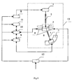
- Fig. 2 is a block diagram of a device according to an embodiment of the invention;
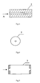
- Fig. 3 is a sectional view of the structure of a round-aperture collimator entrance diaphragm according to an embodiment of the invention;
- Fig. 4 is a view in direction A of Fig.3;
- Fig. 5 is a sectional view of the structure of a rectangular-aperture collimator entrance diaphragm according to an embodiment of the invention;
- Fig. 6 is a view in direction A of Fig.5;
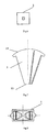
- Fig. 7 is a sectional view of the structure of a tapered position-restricting receiving slit according to an embodiment of the invention, with a larger opening at the
upper end 14 and a smaller opening at thelower end 15; - Fig. 8 is a top view of Fig.7;
- Fig. 9 is a schematic diagram of measurement with the work piece being moved according to an embodiment of the invention;
- Fig. 10 is a block diagram of the measurement and calculation according to an embodiment of the invention;
- Fig. 11 is a diffraction pattern for the central part in a magnesium alloy work piece in a thickness of 25mm.
- In the figures, 1 represents a X-ray tube; 2 a collimator entrance diaphragm; 3 a work piece; 4 a table; 5 a receiving slit; 6 a detector; 7 a goniometer; 8 a power source for an X-ray generator; 9 a energy analyzer; 10 a computer; 11a data output unit; 12 a voltage stabilizer; 13 a platform for fixing the measuring device; 14 a larger opening at the upper end of a tapered position-restricting receiving slit; 15 a smaller opening at the lower end of the tapered position-restricting receiving slit.
- Hereunder the invention is described in detail in preferred embodiments, with reference to the attached drawings. First, it should be noted that the terms, words, and the meanings of the claims in this invention shall not be understood with their literal and ordinary meanings; instead, they also contain implications and concepts associated with the techniques provided in the invention, because, as the inventors, we have to provide appropriate definitions for the terms, so as to describe the invention in the most appropriate way. Therefore, the configurations described in embodiments of the invention and shown in the attached drawings are only preferred solutions instead of covering all technical features of the invention. It should be appreciated that there may be various equivalent or modified solutions to substitute those provided here.
- In a first embodiment, as shown in the figures, a short-wavelength X-ray diffraction measuring device includes an
X-ray tube 1, anentrance diaphragm 2, a table 4, a receivingslit 5, agoniometer 7, adetector 6, and anenergy analyzer 9; wherein, theX-ray tube 1 and thedetector 6 are located at the two sides of the table, i.e., at the two sides of a measured work piece. - The receiving
slit 5 and thedetector 6 are fixed to thegoniometer 7 and can be rotated synchronously around a measured part of awork piece 3 on the table 4. The measured part is located on a rotating axis of thegoniometer 7. Thegoniometer 7 is fixed to aplatform 13. The table 4 is fixed to thegoniometer 7 or theplatform 13. TheX-ray tube 1 is fixed to thegoniometer 7 or theplatform 13. Theentrance diaphragm 2 is fixed to thegoniometer 7, theplatform 13, or a clamp for theX-ray tube 1; an exit of thediaphragm 2 is on or within the circumference of thegoniometer 7. The measured work piece on the table 4 can be translated along with the table 4 in X, Y, Z three dimensions, rotated around the rotating axis of thegoniometer 7 to an angle Ψ, or moved in X, Y, Z three dimensions and to an angle Ψ in a cooperative manner. - In an embodiment of the invention, an anode target of the
X-ray tube 1 is made of a heavy metal material such as W, Au, or Ag. The tube voltage is 320KV and the tube current is 5mA, adjustable steplessly, so that theX-ray tube 1 can emit a short-wavelength characteristic X-ray at a wave length of 0.01nm-0.07nm with a strong penetration capability, which can penetrate to a depth of dm level in metal, non-metal, or ceramic material with a low atomic number (Z<20), such as Al, Mg, Si, etc. Thedetector 6 is a position-sensitive detector. Theentrance diaphragm 2 is a collimator entrance diaphragm. The receivingslit 5 is a tapered position-restricting receiving slit for shielding scattered X-rays incident to thedetector 6 and diffracted rays from any other part of the work piece, i.e., it only permits the diffracted rays from the measured part entering into the detector and shields the remaining rays. Theenergy analyzer 9 is a multi-channel energy analyzer. The table 4 can be translated in X, Y, Z three dimensions and rotated around the rotating axis of thegoniometer 7 under the control of thecomputer 10. Signals from themulti-channel energy analyzer 9 are inputted to thecomputer 10. - The distance from the
X-ray tube 1 to the center of the circle of thegoniometer 7 is equal or not equal to the distance from thedetector 6 to the center of the circle of thegoniometer 7, and is adjustable. The distance from the center of the circle of thegoniometer 7 to the radiation detector or position-sensitive detector is 600mm. - The collimator entrance diaphragm is a round-aperture collimator entrance diaphragm or rectangular-aperture collimator entrance diaphragm. The barrier material for the collimator entrance diaphragm is Pb or a heavy metal with stronger X-ray absorption capability than Pb. If a single-point radiation detector, such as a scintillation counter, is used to scan and collect a diffraction pattern, a round-aperture collimator entrance diaphragm or rectangular-aperture collimator entrance diaphragm is used for the parallel position-restricting receiving slit.
- The round-aperture collimator entrance diaphragm is in an inner diameter of 0.1-2mm and a length of 50-200mm. The rectangular-aperture collimator entrance diaphragm is composed of two or more diaphragms, which are parallel to each other in the same direction and the center lines of which coincide with each other. The barrier material for each diaphragm is in a thickness of 5mm. The spacing between the diaphragms is 180mm. The inner aperture of each diaphragm is of (1-4)×(0.1-0.8)mm. The total thickness of the barrier materials for the entire rectangular-aperture collimator entrance diaphragm is not less than 15mm.
- A lead sheet or a heavy metal sheet with a stronger X-ray absorption capability in a thickness greater than 2mm is used for the radiation detector or position-sensitive detector to shield X-rays, leaving only a window over against the receiving
slit 5 and a pinhole for leading out electric wires. - The taper of the tapered position-restricting receiving slit depends on a limited angle detectable by the position-sensitive detector. A casing of the tapered position-restricting receiving slit is covered with a lead sheet in a thickness greater than 2mm, and lined with 3-10 tungsten or molybdenum plates that divide the taper of the tapered position-restricting receiving slit evenly. The dimension of a
larger opening 14 of the slit matches the effective dimension of the position-sensitive detector, and the slit is fixed to the position-sensitive detector. The tapered surface of the tapered position-restricting receiving slit intersects with the extension of the lined tungsten or molybdenum plate at the rotating axis of the goniometer, wherein the center line of the tapered position-restricting receiving slit intersects with the center line of the lined tungsten or molybdenum plate at the center of the goniometer circle. The tapered position-restricting receiving slit and the position-sensitive detector can be moved in a cooperative way. If a position-sensitive detector is used to collect a diffraction pattern, a tapered position-restricting receiving slit is used as the receiving slit. - A short-wavelength X-ray diffraction measuring method for the above device, in which a short-wavelength X-ray diffraction and transmission method is employed, includes: (1) selecting radiation and diffraction test parameters, including tube voltage, tube current, diaphragm and slit system, and the distance from the center of the goniometer circle to the radiation detector or position-sensitive detector; (2) placing the measured part on the work piece at the center of the goniometer circle under the control of the computer; (3) measuring the diffraction pattern under the control of the computer; (4) moving the table in X, Y, Z three dimensions or rotating around the rotating axis of the goniometer as required under the control of the computer, so as to measure the diffraction pattern at any part in or at any rotated angle Ψ of the work piece; (5) processing the data under the control of the computer and obtaining the phase, residual stress parameters, and their distribution at the measured parts.
- Selection of radiation and diffraction test parameters may be as follows: WKα, AuKα, or AgKα short-wavelength X radiation is selected; an X-ray diffraction and transmission method is chosen; a parallel position-restricting receiving slit or tapered position-restricting receiving slit is used to permit only the diffracted rays from the measured part entering into the detector and shield the remaining rays.
- The measured part of the work piece is placed at the center of the goniometer circle under the control of the computer; the measured part is any part inside of the work piece within a measurable thickness range. In order to implement part-by-part tomoscan, the measured
work piece 3 on the table 4 shown in Fig.9 is controlled by the computer to move in three dimensions at a step length of 0.1-2mm. In order to measure a diffraction pattern for a measured part in any direction, thework piece 3 on the table 4 shown in Fig.9 can be controlled by the computer to rotate to a certain angle around the rotating axis of the goniometer. The computer processes the obtained data and the output unit outputs the phase, residual stress parameters, and their distribution at individual parts in the measured work piece. - In a second embodiment, as shown in Fig.9, the device and method used in this embodiment are identical to those used in the first embodiment, with the difference in parameter selection: in this embodiment, WKα radiation is used, the tube voltage is 280KV, the tube current is 3mA, the distance from the center of the goniometer circle to the radiation detector is 220mm±1.0, a
NaI scintillation counter 6 is connected to themulti-channel energy analyzer 9, the collimator entrance diaphragm is a round-aperture collimator entrance diaphragm in an inner diameter of 2mm±0.1 and a length of 120mm±0.5 length, a round-aperture collimator entrance diaphragm in an inner diameter of 0.5mm±0.1 and a length of 120mm±0.5 is used for the position-restricting receiving slit, and theNal scintillation counter 6 is shielded with an 8mm±0.1 thick lead sheet. After the optical path is conditioned, a magnesium alloy casting 3 in a thickness of 25mm±0.5 is placed on the table 4. The table 4 is adjusted so that the center of the magnesium alloy casting 3 is located in the center of the circle of the goniometer. The position indicated by the dotted line shown in Fig.9 is an actual position of the magnesium alloy casting 3; in that case, the center of the circle of the goniometer is located inside of the magnesium alloy casting 3 with a distance of 12.5mm±0.1 to the surface of the casting. The scan range 2θ is 2-10°, the step length of scan is 0.05°, and the measurement is performed for 10s at each step. An obtained X-ray diffraction pattern is shown in Fig.11. - In a third embodiment, the device and method used in this embodiment are identical to those used in the first embodiment, with the difference in parameter selection: in this embodiment, WKα radiation is used, the tube voltage is 320KV, the tube current is 6mA, the distance from the center of the goniometer circle to the radiation detector is 500mm±1.0, a
NaI scintillation counter 6 is connected to themulti-channel energy analyzer 9, the collimator entrance diaphragm is a round-aperture collimator entrance diaphragm in an inner diameter of 1mm±0.1 and a length of 150mm±0.5, a round-aperture collimator entrance diaphragm in an inner diameter of 0.8mm±0.1 and a length of 120mm±0.5 is used for the position-restricting receiving slit, and theNaI scintillation counter 6 is shielded with a 10mm±0.1 thick lead sheet. After the optical path is conditioned, thework piece 3 is placed on the table 4. The table 4 is adjusted so that the center of thework piece 3 is located at the center of the circle of the goniometer; in that case, the center of the circle of the goniometer is located inside of thework piece 3. The scan range 2θ is 2-10°, the step length of scan is 0.05°, and the measurement is performed for 10s at each step. - Though the invention is disclosed in the embodiments as above, it should be noted that those embodiments do not constitute any limitation to the invention. Any variations conceivable by those skilled in the art shall fall into the scope of the invention.
Claims (22)
- A short-wavelength X-ray diffraction measuring device, comprising an X-ray tube (1), an entrance diaphragm (2), a table (4), a goniometer (7), a detector (6), and an energy analyzer (9); wherein, the X-ray tube (1) and the detector (6) are located at the two sides of the table (4); the detector (6) receives transmitted diffracted X-rays.
- The short-wavelength X-ray diffraction measuring device according to claim 1, wherein, the entrance diaphragm (2) is a collimator entrance diaphragm, comprising: a round-aperture collimator entrance diaphragm or a rectangular-aperture collimator entrance diaphragm.
- The short-wavelength X-ray diffraction measuring device according to claim 2, wherein, the collimator entrance diaphragm is mainly made of barrier material comprising Pb or a heavy metal with a stronger X-ray absorption capability than Pb.
- The short-wavelength X-ray diffraction measuring device according to claim 1, further comprising a receiving slit (5) located between the table (4) and the detector (6).
- The short-wavelength X-ray diffraction measuring device according to claim 4, wherein, the receiving slit (5) is a parallel position-restricting receiving slit or a tapered position-restricting receiving slit configured to shield scattered X-rays incident to the detector (6) or diffracted rays from other parts of a work piece.
- The short-wavelength X-ray diffraction measuring device according to claim 5, wherein, the receiving slit (5) is mainly made of barrier material comprising Pb or another heavy metal with a stronger X-ray absorption capability than Pb.
- The short-wavelength X-ray diffraction measuring device according to claim 5, wherein, the taper of the tapered position-restricting receiving slit depends on a limited angle detectable by the position-sensitive detector; a casing of the tapered position-restricting receiving slit is covered with a lead sheet in a thickness greater than 2mm, and inlaid with 3-10 tungsten or molybdenum plates that divide the taper of the tapered position-restricting receiving slit evenly; the dimension of a larger opening (14) of the slit matches the effective dimension of the position-sensitive detector, and the slit is fixed to the position-sensitive detector; the tapered surface of the tapered position-restricting receiving slit intersects with the extension of the inlaid tungsten or molybdenum plates at the rotating axis of the goniometer (7); the center line of the tapered position-restricting receiving slit intersects with the center line of the lined tungsten or molybdenum plate at the center of the circle of the goniometer (7); the tapered position-restricting receiving slit and the position-sensitive detector are movable in an cooperative manner; if a position-sensitive detector is used to collect a diffraction pattern, a tapered position-restricting receiving slit is used as the receiving slit.
- The short-wavelength X-ray diffraction measuring device according to claim 1 or 4, wherein, the receiving slit (5) and the detector (6) are fixed to the goniometer (7) and synchronously rotatable around a measured part in the work piece (3) on the table (4), the measured part is on the rotating axis of the goniometer (7); the goniometer (7) is fixed to a platform (13); the table (4) is fixed to the goniometer (7) or the platform (13); the X-ray tube (1) is fixed to the goniometer (7) or the platform (13); the entrance diaphragm (2) is fixed to the goniometer (7), the platform (13), or a clamp for the X-ray tube (1); an exit of the diaphragm (2) is on or within the circumference of the goniometer (7); the measured work piece (3) on the table (4) is translatable along with the table (4) in X, Y, Z three dimensions, rotatable around the rotating axis of the goniometer (7) to an angle ψ, or movable in X, Y, Z three dimensions and to an angle Ψ in a cooperative manner.
- The short-wavelength X-ray diffraction measuring device according to claim 1 or 4, wherein, the detector (6) comprises a radiation detector, a position-sensitive detector, or a one-dimensional semiconductor detector array.
- The short-wavelength X-ray diffraction measuring device according to claim 9, wherein, the detector (6) is packaged by a lead sheet in a thickness greater than 2mm or another heavy metal sheet with a stronger X-ray absorption capability than Pb to shield X-rays, leaving only a window over against the receiving slit (5) and a pinhole for leading out electric wires.
- The short-wavelength X-ray diffraction measuring device according to claim 1 or 4, wherein, the energy analyzer (9) is a single-channel energy analyzer or a multi-channel energy analyzer.
- The short-wavelength X-ray diffraction measuring device according to claim 1 or 4, wherein, an anode target of the X-ray tube (1) is made of a heavy metal material such as W, Au, or Ag; the tube voltage is 120-350KV and the tube current is 2-10mA, adjustable steplessly.
- The short-wavelength X-ray diffraction measuring device according to claim 1 or 4, wherein, the table (4) is translatable in X, Y, and Z three dimensions or rotatable around the rotating axis of the goniometer (7) under the control of the computer (10); the energy analyzer (9) outputs signals to the computer (10).
- The short-wavelength X-ray diffraction measuring device according to claim 1 or 4, wherein, the distance from the X-ray tube (1) to the center of the circle of the goniometer (7) is equal or not equal to the distance from the detector (6) to the center of the circle of the goniometer (7), and is adjustable; the distance from the center of the circle of the goniometer (7) to the radiation detector or position-sensitive detector is 200-800mm; the center of the circle of the goniometer is an intersection point between the rotating axis of the goniometer and a rotation plane of the radiation detector or position-sensitive detector; an incident X-ray is in the rotation plane of the radiation detector or position-sensitive detector and passes through the center of the circle of the goniometer; a part of the work piece at the center of the circle of the goniometer is the measured part; if the single-point radiation detector, such as a scintillation counter is used to scan and collect a diffraction pattern, a round-aperture collimator entrance diaphragm or a rectangular-aperture collimator entrance diaphragm is used for the parallel position-restricting receiving slit.
- The short-wavelength X-ray diffraction measuring device according to claim 2 or 14, wherein, the round-aperture collimator entrance diaphragm is in an inner diameter of 0.1-2mm and a length of 50-200mm; the rectangular-aperture collimator entrance diaphragm is composed of two or more diaphragms, which are parallel to each other in the same direction and the center lines of which coincide with each other; the barrier material for each diaphragm is in a thickness of ≥4mm; the spacing between the diaphragms is 20-200mm; an inner aperture of each diaphragm is of (1-4)×(0.1-0.8)mm; the total thickness of the barrier materials for the entire rectangular-aperture collimator entrance diaphragm is not less than 15mm.
- A short-wavelength X-ray diffraction measuring method, comprising the following steps:1) placing a detector (6) and an X-ray tube (1) at two sides of a table (4), so that the detector (6) can receive a transmitted diffracted X-ray radiated from the X-ray tube (1) to a measured part of a work piece on the table (4);2) selecting radiation and diffraction test parameters, including tube voltage, tube current, entrance diaphragm and receiving slit system, and the distance from the center of the circle of a goniometer to the detector;3) placing the measured part of the work piece at the center of the circle of the goniometer;4) measuring a diffraction pattern;5) processing data by a computer to obtain phase, residual stress parameters at different parts, and their distribution.
- The short-wavelength X-ray diffraction measuring method according to claim 16, wherein, selecting radiation and diffraction test parameters comprises using WKα, AuKα, or AgKα short-wavelength X radiation.
- The short-wavelength X-ray diffraction measuring method according to claim 16, wherein, the receiving slit permits only diffracted rays from the measured part entering into the detector but shields the remaining rays, and comprises a parallel position-restricting receiving slit when a single-point radiation detector, such as a scintillation counter, is used to scan and collect the diffraction pattern, or a tapered position-restricting receiving slit when a position-sensitive detector, is used to collect the diffraction pattern.
- The short-wavelength X-ray diffraction measuring method according to claim 16, wherein, the entrance diaphragm is a collimator entrance diaphragm, comprising: a round-aperture collimator entrance diaphragm or a rectangular-aperture collimator entrance diaphragm.
- The short-wavelength X-ray diffraction measuring method according to claim 16, wherein, the detector is packaged by a lead sheet in a thickness greater than 2mm or another heavy metal sheet with a stronger X-ray absorption capability than Pb to shield X-rays, leaving only a window over against the receiving slit (5) and a pinhole for leading out electric wires.
- The short-wavelength X-ray diffraction measuring method according to claim 16, wherein, the measured part in the work piece is placed at the center of the goniometer circle under the control of the computer; the measured part is any part on the surface of the work piece or inside of the work piece within a measurable thickness range.
- The short-wavelength X-ray diffraction measuring method according to claim 16, wherein, during measurement of the diffraction pattern, the measured work piece (3) is translated along with the table (4) in X, Y, Z three dimensions at a step length of 0.1-2mm and/or rotated around a rotating axis of the goniometer (7) as required under the control of the computer, so as to measure the diffraction pattern at any part in the work piece or at any rotated angle around the rotating axis of the goniometer (7).
Priority Applications (1)
| Application Number | Priority Date | Filing Date | Title |
|---|---|---|---|
| EP12183863.5A EP2541238B1 (en) | 2004-07-14 | 2005-06-30 | A measuring device for the short-wavelength X-ray diffraction and a method thereof |
Applications Claiming Priority (2)
| Application Number | Priority Date | Filing Date | Title |
|---|---|---|---|
| CNB2004100688802A CN100485373C (en) | 2004-07-14 | 2004-07-14 | Short wave length X-ray diffraction measuring device and method |
| PCT/CN2005/000950 WO2006005246A1 (en) | 2004-07-14 | 2005-06-30 | A measuring device for the shortwavelength x ray diffraction and a method thereof |
Related Child Applications (1)
| Application Number | Title | Priority Date | Filing Date |
|---|---|---|---|
| EP12183863.5A Division EP2541238B1 (en) | 2004-07-14 | 2005-06-30 | A measuring device for the short-wavelength X-ray diffraction and a method thereof |
Publications (2)
| Publication Number | Publication Date |
|---|---|
| EP1767928A1 true EP1767928A1 (en) | 2007-03-28 |
| EP1767928A4 EP1767928A4 (en) | 2011-03-16 |
Family
ID=34604191
Family Applications (2)
| Application Number | Title | Priority Date | Filing Date |
|---|---|---|---|
| EP12183863.5A Expired - Lifetime EP2541238B1 (en) | 2004-07-14 | 2005-06-30 | A measuring device for the short-wavelength X-ray diffraction and a method thereof |
| EP05759557A Withdrawn EP1767928A4 (en) | 2004-07-14 | 2005-06-30 | A measuring device for the shortwavelength x ray diffraction and a method thereof |
Family Applications Before (1)
| Application Number | Title | Priority Date | Filing Date |
|---|---|---|---|
| EP12183863.5A Expired - Lifetime EP2541238B1 (en) | 2004-07-14 | 2005-06-30 | A measuring device for the short-wavelength X-ray diffraction and a method thereof |
Country Status (5)
| Country | Link |
|---|---|
| US (1) | US7583788B2 (en) |
| EP (2) | EP2541238B1 (en) |
| JP (1) | JP2008506127A (en) |
| CN (1) | CN100485373C (en) |
| WO (1) | WO2006005246A1 (en) |
Cited By (4)
| Publication number | Priority date | Publication date | Assignee | Title |
|---|---|---|---|---|
| CN102706905A (en) * | 2012-06-28 | 2012-10-03 | 丹东奥龙射线仪器有限公司 | Data recorder of X-ray crystal orientation device |
| CN103901063A (en) * | 2014-04-23 | 2014-07-02 | 哈尔滨工业大学 | Method for testing C-fiber reinforced resin based composite material by virtue of X-ray diffraction |
| EP3258254B1 (en) * | 2016-06-15 | 2022-12-14 | Rigaku Corporation | X-ray diffractometer |
| EP4109083A1 (en) * | 2021-06-25 | 2022-12-28 | The 59th Institute of China Ordonance Industry | Device and method for measuring short-wavelength characteristic x-ray diffraction based on array detection |
Families Citing this family (28)
| Publication number | Priority date | Publication date | Assignee | Title |
|---|---|---|---|---|
| US7840237B2 (en) | 2007-02-08 | 2010-11-23 | Microsoft Corporation | Enabling user interface elements based on short range wireless devices |
| JP2009025234A (en) * | 2007-07-23 | 2009-02-05 | Rigaku Corp | Hard tissue evaluation method |
| US7978820B2 (en) * | 2009-10-22 | 2011-07-12 | Panalytical B.V. | X-ray diffraction and fluorescence |
| US8477904B2 (en) * | 2010-02-16 | 2013-07-02 | Panalytical B.V. | X-ray diffraction and computed tomography |
| CN102435626A (en) * | 2011-09-13 | 2012-05-02 | 丹东通达科技有限公司 | Table type X-ray diffractometer |
| CN103245445A (en) * | 2013-05-17 | 2013-08-14 | 北京师范大学 | Stress meter |
| JP6127717B2 (en) * | 2013-05-24 | 2017-05-17 | 株式会社島津製作所 | X-ray analyzer |
| CN105339781B (en) * | 2013-08-21 | 2018-12-04 | 联合工艺公司 | Method for in-situ marking for thermo-mechanical structure health monitoring |
| CN103592321A (en) * | 2013-11-13 | 2014-02-19 | 常熟市宝华建筑装璜材料有限公司 | Steel pipe detection device based on X-ray detection |
| CN104634799A (en) * | 2013-11-15 | 2015-05-20 | 郑琪 | Device and method for measuring multi-wavelength characteristic X ray diffraction |
| CN105021331A (en) * | 2014-04-29 | 2015-11-04 | 上海理工大学 | Method for measuring residual stress of polycrystalline material based on X-ray diffraction full spectrum |
| KR102303973B1 (en) | 2014-12-22 | 2021-09-23 | 삼성전자주식회사 | Apparatus for forming a thin layer and method of forming a thin layer on a substrate using the same |
| CN104502385A (en) * | 2014-12-30 | 2015-04-08 | 西南技术工程研究所 | Short-wavelength X-ray diffraction plate-like internal stress fixed-point non-destructive testing method |
| CN104597065A (en) * | 2015-01-23 | 2015-05-06 | 中国工程物理研究院材料研究所 | X-ray diffractometer |
| CN104764761B (en) * | 2015-04-23 | 2017-05-10 | 中国工程物理研究院材料研究所 | Method for measuring phase transition of substance under high static pressure |
| EP3550292B1 (en) * | 2016-11-29 | 2021-10-27 | Rigaku Corporation | X-ray reflectometer |
| CN109324072B (en) * | 2017-07-28 | 2021-05-14 | 中国科学院苏州纳米技术与纳米仿生研究所 | Detection system and detection method of high-throughput composite material chip |
| CN107703168A (en) * | 2017-10-13 | 2018-02-16 | 中国工程物理研究院材料研究所 | A kind of crystal diffraction signal acquiring method |
| CN109374659B (en) * | 2017-12-28 | 2020-12-29 | 中国兵器工业第五九研究所 | A kind of positioning method of short wavelength X-ray diffraction test sample |
| JP6871629B2 (en) * | 2018-06-29 | 2021-05-12 | 株式会社リガク | X-ray analyzer and its optical axis adjustment method |
| CN111380880B (en) | 2018-12-28 | 2023-04-07 | 中国兵器工业第五九研究所 | Diffraction device and method for nondestructive testing of crystal orientation uniformity inside workpiece |
| CN109444948B (en) * | 2018-12-29 | 2024-05-14 | 中国原子能科学研究院 | Ionization chamber for absolute measurement of air kerma |
| KR20220062040A (en) | 2019-09-12 | 2022-05-13 | 올쏘스캔 인코포레이티드 | Mini C-Arm Imaging System with Stepless Collimation |
| CN110596160B (en) * | 2019-09-19 | 2020-12-25 | 西安交通大学 | Monochromatic X-ray single crystal/oriented crystal stress measuring system and measuring method |
| CN113740366B (en) * | 2020-05-27 | 2023-11-28 | 中国兵器工业第五九研究所 | Methods and devices for non-destructive detection of crystal orientation differences and grain boundary defects within single crystals or oriented crystals |
| CN113176285B (en) * | 2021-04-23 | 2023-12-15 | 中国兵器工业第五九研究所 | Nondestructive testing method for residual stress in short-wavelength characteristic X-ray |
| JP7687689B2 (en) * | 2022-02-14 | 2025-06-03 | 株式会社リガク | X-ray diffraction apparatus and measurement method |
| CN117168372B (en) * | 2023-10-23 | 2024-01-23 | 北京华力兴科技发展有限责任公司 | X-ray metal coating thickness gauge |
Family Cites Families (37)
| Publication number | Priority date | Publication date | Assignee | Title |
|---|---|---|---|---|
| DE1598413A1 (en) | 1966-01-20 | 1970-04-23 | Exxon Research Engineering Co | Device for creating distortion-free X-ray diffraction images |
| US3527942A (en) | 1967-11-09 | 1970-09-08 | Atlantic Richfield Co | Automatic sample changer for positioning a plurality of pellets in an x-ray analyzer |
| DE2312507A1 (en) * | 1973-03-13 | 1974-09-26 | Max Planck Gesellschaft | DEVICE FOR X-RAY DIFFICULTY MEASUREMENTS USING WHITE X-RAYS |
| JPS6093335A (en) * | 1983-10-27 | 1985-05-25 | Natl Inst For Res In Inorg Mater | Detection and measurement device for crystal grain state of polycrystalline material |
| JPH01265146A (en) * | 1988-04-16 | 1989-10-23 | Mc Sci:Kk | X-ray diffraction device |
| US4877080A (en) | 1988-06-13 | 1989-10-31 | Ahlstromforetagen Svenska Ab | Process and apparatus for cooling a fluid |
| GB8830466D0 (en) | 1988-12-31 | 1989-03-01 | Salje Ekhard K H | X-ray diffractometer |
| CA2022190C (en) | 1989-08-11 | 2002-06-04 | Andrew W. Gross | Thiol-terminated hydroxyamides |
| JP2899057B2 (en) * | 1990-04-09 | 1999-06-02 | 理学電機株式会社 | Automatic optical axis adjuster for sample fixed X-ray diffractometer |
| CN2077546U (en) | 1990-05-24 | 1991-05-22 | 中国科学院物理研究所 | Dual-purpose x-ray double-crystal diffractometer |
| GB9122085D0 (en) * | 1991-10-17 | 1991-11-27 | Cambridge Surface Analytics | X-ray diffractometer |
| US5259013A (en) * | 1991-12-17 | 1993-11-02 | The United States Of America As Represented By The Secretary Of Commerce | Hard x-ray magnification apparatus and method with submicrometer spatial resolution of images in more than one dimension |
| GB2266040B (en) * | 1992-04-09 | 1996-03-13 | Rigaku Ind Corp | X-ray analysis apparatus |
| JPH05296948A (en) * | 1992-04-17 | 1993-11-12 | Nippon Steel Corp | X-ray diffraction ring omnidirectional measuring device |
| JP2905659B2 (en) * | 1993-02-26 | 1999-06-14 | シャープ株式会社 | X-ray apparatus and evaluation analysis method using the apparatus |
| JPH06258260A (en) * | 1993-03-05 | 1994-09-16 | Seiko Instr Inc | X-ray diffractometer |
| CN1038874C (en) * | 1994-04-12 | 1998-06-24 | 中国科学院上海原子核研究所 | Microarea X-ray fluorescent golden ornaments analytical device |
| DE19512819C2 (en) | 1995-04-05 | 1999-05-27 | Siemens Ag | X-ray computer tomograph |
| GB9519687D0 (en) * | 1995-09-27 | 1995-11-29 | Schlumberger Ltd | Method of determining earth formation characteristics |
| US6005913A (en) * | 1996-04-01 | 1999-12-21 | Siemens Westinghouse Power Corporation | System and method for using X-ray diffraction to detect subsurface crystallographic structure |
| US5949811A (en) * | 1996-10-08 | 1999-09-07 | Hitachi Medical Corporation | X-ray apparatus |
| CN1049496C (en) * | 1997-02-03 | 2000-02-16 | 重庆大学 | X-ray residual stress measuring device and method |
| JP4040770B2 (en) | 1998-01-20 | 2008-01-30 | ジーイー横河メディカルシステム株式会社 | X-ray CT system |
| DE19839472C1 (en) | 1998-08-29 | 2000-11-02 | Bruker Axs Analytical X Ray Sy | Automatic sample changer for X-ray diffractometers |
| JP3950239B2 (en) * | 1998-09-28 | 2007-07-25 | 株式会社リガク | X-ray equipment |
| WO2000036405A2 (en) | 1998-12-18 | 2000-06-22 | Symyx Technologies, Inc. | Apparatus and method for characterizing libraries of different materials using x-ray scattering |
| JP4155538B2 (en) * | 1999-06-30 | 2008-09-24 | 株式会社リガク | X-ray measuring apparatus and X-ray measuring method |
| JP2001095789A (en) | 1999-09-30 | 2001-04-10 | Shimadzu Corp | X-ray fluoroscope |
| CN1291720A (en) | 1999-10-11 | 2001-04-18 | 成都理工学院 | Technology for manufacturing portable fluorescent instrument with X ray excited by tube |
| US6895075B2 (en) * | 2003-02-12 | 2005-05-17 | Jordan Valley Applied Radiation Ltd. | X-ray reflectometry with small-angle scattering measurement |
| JP4533553B2 (en) * | 2001-04-13 | 2010-09-01 | 株式会社リガク | X-ray tube |
| CN2496018Y (en) | 2001-10-08 | 2002-06-19 | 中国科学院物理研究所 | Multifunctional X-ray diffractometer |
| WO2003060497A1 (en) | 2002-01-15 | 2003-07-24 | Avantium International B.V. | Method for performing powder diffraction analysis |
| GB0201773D0 (en) * | 2002-01-25 | 2002-03-13 | Isis Innovation | X-ray diffraction method |
| JP2003329620A (en) * | 2002-05-13 | 2003-11-19 | Hitachi Ltd | Inspection method for laminated thin film |
| CN1270176C (en) * | 2002-12-02 | 2006-08-16 | 中国科学技术大学 | Method and apparatus for measuring and analyzing structure and component of combined sample |
| JP3731207B2 (en) * | 2003-09-17 | 2006-01-05 | 株式会社リガク | X-ray analyzer |
-
2004
- 2004-07-14 CN CNB2004100688802A patent/CN100485373C/en not_active Expired - Lifetime
-
2005
- 2005-06-30 WO PCT/CN2005/000950 patent/WO2006005246A1/en not_active Ceased
- 2005-06-30 EP EP12183863.5A patent/EP2541238B1/en not_active Expired - Lifetime
- 2005-06-30 US US11/572,128 patent/US7583788B2/en not_active Expired - Lifetime
- 2005-06-30 JP JP2007520648A patent/JP2008506127A/en active Pending
- 2005-06-30 EP EP05759557A patent/EP1767928A4/en not_active Withdrawn
Cited By (5)
| Publication number | Priority date | Publication date | Assignee | Title |
|---|---|---|---|---|
| CN102706905A (en) * | 2012-06-28 | 2012-10-03 | 丹东奥龙射线仪器有限公司 | Data recorder of X-ray crystal orientation device |
| CN103901063A (en) * | 2014-04-23 | 2014-07-02 | 哈尔滨工业大学 | Method for testing C-fiber reinforced resin based composite material by virtue of X-ray diffraction |
| EP3258254B1 (en) * | 2016-06-15 | 2022-12-14 | Rigaku Corporation | X-ray diffractometer |
| EP4109083A1 (en) * | 2021-06-25 | 2022-12-28 | The 59th Institute of China Ordonance Industry | Device and method for measuring short-wavelength characteristic x-ray diffraction based on array detection |
| US12099025B2 (en) | 2021-06-25 | 2024-09-24 | The 59Th Institute Of China Ordnance Industry | Device and method for measuring short-wavelength characteristic X-ray diffraction based on array detection |
Also Published As
| Publication number | Publication date |
|---|---|
| US7583788B2 (en) | 2009-09-01 |
| JP2008506127A (en) | 2008-02-28 |
| WO2006005246A1 (en) | 2006-01-19 |
| EP2541238B1 (en) | 2015-12-16 |
| EP2541238A1 (en) | 2013-01-02 |
| CN100485373C (en) | 2009-05-06 |
| EP1767928A4 (en) | 2011-03-16 |
| CN1588019A (en) | 2005-03-02 |
| US20080095311A1 (en) | 2008-04-24 |
Similar Documents
| Publication | Publication Date | Title |
|---|---|---|
| EP2541238B1 (en) | A measuring device for the short-wavelength X-ray diffraction and a method thereof | |
| EP2564186B1 (en) | Method and apparatus for using an area x-ray detector as a point detector in an x-ray diffractometer | |
| EP2085772B1 (en) | Apparatus and method for X-ray fluorescence analysis of a mineral sample | |
| US5745543A (en) | Apparatus for simultaneous X-ray diffraction and X-ray fluorescence measurements | |
| RU2506570C1 (en) | Method and device for performance of x-ray analysis of sample | |
| CN115598157B (en) | A short-wavelength characteristic X-ray diffraction device and method based on array detection | |
| CN109991253A (en) | A capillary focused microbeam X-ray diffractometer | |
| CN104634799A (en) | Device and method for measuring multi-wavelength characteristic X ray diffraction | |
| JP5403728B2 (en) | Neutron diffractometer | |
| JP2012108126A (en) | Diffractometer | |
| EP2591342B1 (en) | An x-ray diffraction contrast tomography (dct) system, and an x-ray diffraction contrast (dct) method using a first and a second x-ray detector | |
| JP2023107744A (en) | Method and system for simultaneously performing X-ray absorption spectroscopy and X-ray fluorescence spectroscopy | |
| CN113176285B (en) | Nondestructive testing method for residual stress in short-wavelength characteristic X-ray | |
| KR102621750B1 (en) | Device and method for measuring material properties of polycrystalline products | |
| CN220188400U (en) | X-ray diffraction and X-ray fluorescence spectrum synchronous combination system and device | |
| Kujala et al. | High resolution short focal distance Bent Crystal Laue Analyzer for copper K edge x-ray absorption spectroscopy | |
| CN109596656B (en) | A laser-assisted total reflection X-fluorescence uranium ore trace element analysis device | |
| JPH0288952A (en) | Method and device for analyzing tissue | |
| KR200418412Y1 (en) | Atomic distance measuring device of crystal using X-ray | |
| JPH07260598A (en) | X-ray stress measuring device and X-ray stress measuring method | |
| JP2759922B2 (en) | Method for measuring high-order X-ray intensity | |
| WO2006095468A1 (en) | X-ray diffraction analyzer and analyzing method | |
| JP2000275192A (en) | X-ray diffractometer | |
| CN116223547A (en) | X-ray diffraction and X-ray fluorescence spectrum synchronous combination system and device | |
| Knipe et al. | ND measurement of residual stress in welded steel bar |
Legal Events
| Date | Code | Title | Description |
|---|---|---|---|
| PUAI | Public reference made under article 153(3) epc to a published international application that has entered the european phase |
Free format text: ORIGINAL CODE: 0009012 |
|
| 17P | Request for examination filed |
Effective date: 20070112 |
|
| AK | Designated contracting states |
Kind code of ref document: A1 Designated state(s): AT BE BG CH CY CZ DE DK EE ES FI FR GB GR HU IE IS IT LI LT LU MC NL PL PT RO SE SI SK TR |
|
| DAX | Request for extension of the european patent (deleted) | ||
| A4 | Supplementary search report drawn up and despatched |
Effective date: 20110215 |
|
| 17Q | First examination report despatched |
Effective date: 20120511 |
|
| STAA | Information on the status of an ep patent application or granted ep patent |
Free format text: STATUS: THE APPLICATION IS DEEMED TO BE WITHDRAWN |
|
| 18D | Application deemed to be withdrawn |
Effective date: 20120922 |