EP1767775B1 - Method of starting spark ignition engine without using starter motor - Google Patents
Method of starting spark ignition engine without using starter motor Download PDFInfo
- Publication number
- EP1767775B1 EP1767775B1 EP06019782A EP06019782A EP1767775B1 EP 1767775 B1 EP1767775 B1 EP 1767775B1 EP 06019782 A EP06019782 A EP 06019782A EP 06019782 A EP06019782 A EP 06019782A EP 1767775 B1 EP1767775 B1 EP 1767775B1
- Authority
- EP
- European Patent Office
- Prior art keywords
- cylinder
- fuel
- engine
- routine
- air
- Prior art date
- Legal status (The legal status is an assumption and is not a legal conclusion. Google has not performed a legal analysis and makes no representation as to the accuracy of the status listed.)
- Ceased
Links
Images


Classifications
-
- F—MECHANICAL ENGINEERING; LIGHTING; HEATING; WEAPONS; BLASTING
- F02—COMBUSTION ENGINES; HOT-GAS OR COMBUSTION-PRODUCT ENGINE PLANTS
- F02B—INTERNAL-COMBUSTION PISTON ENGINES; COMBUSTION ENGINES IN GENERAL
- F02B23/00—Other engines characterised by special shape or construction of combustion chambers to improve operation
- F02B23/08—Other engines characterised by special shape or construction of combustion chambers to improve operation with positive ignition
- F02B23/10—Other engines characterised by special shape or construction of combustion chambers to improve operation with positive ignition with separate admission of air and fuel into cylinder
- F02B23/104—Other engines characterised by special shape or construction of combustion chambers to improve operation with positive ignition with separate admission of air and fuel into cylinder the injector being placed on a side position of the cylinder
-
- F—MECHANICAL ENGINEERING; LIGHTING; HEATING; WEAPONS; BLASTING
- F02—COMBUSTION ENGINES; HOT-GAS OR COMBUSTION-PRODUCT ENGINE PLANTS
- F02D—CONTROLLING COMBUSTION ENGINES
- F02D13/00—Controlling the engine output power by varying inlet or exhaust valve operating characteristics, e.g. timing
- F02D13/02—Controlling the engine output power by varying inlet or exhaust valve operating characteristics, e.g. timing during engine operation
- F02D13/0223—Variable control of the intake valves only
- F02D13/0234—Variable control of the intake valves only changing the valve timing only
-
- F—MECHANICAL ENGINEERING; LIGHTING; HEATING; WEAPONS; BLASTING
- F02—COMBUSTION ENGINES; HOT-GAS OR COMBUSTION-PRODUCT ENGINE PLANTS
- F02N—STARTING OF COMBUSTION ENGINES; STARTING AIDS FOR SUCH ENGINES, NOT OTHERWISE PROVIDED FOR
- F02N99/00—Subject matter not provided for in the other groups of this subclass
- F02N99/002—Starting combustion engines by ignition means
- F02N99/006—Providing a combustible mixture inside the cylinder
-
- F—MECHANICAL ENGINEERING; LIGHTING; HEATING; WEAPONS; BLASTING
- F02—COMBUSTION ENGINES; HOT-GAS OR COMBUSTION-PRODUCT ENGINE PLANTS
- F02B—INTERNAL-COMBUSTION PISTON ENGINES; COMBUSTION ENGINES IN GENERAL
- F02B23/00—Other engines characterised by special shape or construction of combustion chambers to improve operation
- F02B23/08—Other engines characterised by special shape or construction of combustion chambers to improve operation with positive ignition
- F02B2023/085—Other engines characterised by special shape or construction of combustion chambers to improve operation with positive ignition using several spark plugs per cylinder
-
- F—MECHANICAL ENGINEERING; LIGHTING; HEATING; WEAPONS; BLASTING
- F02—COMBUSTION ENGINES; HOT-GAS OR COMBUSTION-PRODUCT ENGINE PLANTS
- F02B—INTERNAL-COMBUSTION PISTON ENGINES; COMBUSTION ENGINES IN GENERAL
- F02B75/00—Other engines
- F02B75/12—Other methods of operation
- F02B2075/125—Direct injection in the combustion chamber for spark ignition engines, i.e. not in pre-combustion chamber
-
- F—MECHANICAL ENGINEERING; LIGHTING; HEATING; WEAPONS; BLASTING
- F02—COMBUSTION ENGINES; HOT-GAS OR COMBUSTION-PRODUCT ENGINE PLANTS
- F02D—CONTROLLING COMBUSTION ENGINES
- F02D13/00—Controlling the engine output power by varying inlet or exhaust valve operating characteristics, e.g. timing
- F02D13/02—Controlling the engine output power by varying inlet or exhaust valve operating characteristics, e.g. timing during engine operation
- F02D13/0203—Variable control of intake and exhaust valves
- F02D13/0207—Variable control of intake and exhaust valves changing valve lift or valve lift and timing
-
- F—MECHANICAL ENGINEERING; LIGHTING; HEATING; WEAPONS; BLASTING
- F02—COMBUSTION ENGINES; HOT-GAS OR COMBUSTION-PRODUCT ENGINE PLANTS
- F02D—CONTROLLING COMBUSTION ENGINES
- F02D41/00—Electrical control of supply of combustible mixture or its constituents
- F02D41/02—Circuit arrangements for generating control signals
- F02D41/04—Introducing corrections for particular operating conditions
- F02D41/06—Introducing corrections for particular operating conditions for engine starting or warming up
- F02D41/062—Introducing corrections for particular operating conditions for engine starting or warming up for starting
-
- F—MECHANICAL ENGINEERING; LIGHTING; HEATING; WEAPONS; BLASTING
- F02—COMBUSTION ENGINES; HOT-GAS OR COMBUSTION-PRODUCT ENGINE PLANTS
- F02M—SUPPLYING COMBUSTION ENGINES IN GENERAL WITH COMBUSTIBLE MIXTURES OR CONSTITUENTS THEREOF
- F02M26/00—Engine-pertinent apparatus for adding exhaust gases to combustion-air, main fuel or fuel-air mixture, e.g. by exhaust gas recirculation [EGR] systems
- F02M26/13—Arrangement or layout of EGR passages, e.g. in relation to specific engine parts or for incorporation of accessories
-
- F—MECHANICAL ENGINEERING; LIGHTING; HEATING; WEAPONS; BLASTING
- F02—COMBUSTION ENGINES; HOT-GAS OR COMBUSTION-PRODUCT ENGINE PLANTS
- F02N—STARTING OF COMBUSTION ENGINES; STARTING AIDS FOR SUCH ENGINES, NOT OTHERWISE PROVIDED FOR
- F02N19/00—Starting aids for combustion engines, not otherwise provided for
- F02N19/005—Aiding engine start by starting from a predetermined position, e.g. pre-positioning or reverse rotation
- F02N2019/007—Aiding engine start by starting from a predetermined position, e.g. pre-positioning or reverse rotation using inertial reverse rotation
-
- F—MECHANICAL ENGINEERING; LIGHTING; HEATING; WEAPONS; BLASTING
- F02—COMBUSTION ENGINES; HOT-GAS OR COMBUSTION-PRODUCT ENGINE PLANTS
- F02P—IGNITION, OTHER THAN COMPRESSION IGNITION, FOR INTERNAL-COMBUSTION ENGINES; TESTING OF IGNITION TIMING IN COMPRESSION-IGNITION ENGINES
- F02P15/00—Electric spark ignition having characteristics not provided for in, or of interest apart from, groups F02P1/00 - F02P13/00 and combined with layout of ignition circuits
- F02P15/08—Electric spark ignition having characteristics not provided for in, or of interest apart from, groups F02P1/00 - F02P13/00 and combined with layout of ignition circuits having multiple-spark ignition, i.e. ignition occurring simultaneously at different places in one engine cylinder or in two or more separate engine cylinders
-
- F—MECHANICAL ENGINEERING; LIGHTING; HEATING; WEAPONS; BLASTING
- F02—COMBUSTION ENGINES; HOT-GAS OR COMBUSTION-PRODUCT ENGINE PLANTS
- F02P—IGNITION, OTHER THAN COMPRESSION IGNITION, FOR INTERNAL-COMBUSTION ENGINES; TESTING OF IGNITION TIMING IN COMPRESSION-IGNITION ENGINES
- F02P5/00—Advancing or retarding ignition; Control therefor
- F02P5/04—Advancing or retarding ignition; Control therefor automatically, as a function of the working conditions of the engine or vehicle or of the atmospheric conditions
- F02P5/145—Advancing or retarding ignition; Control therefor automatically, as a function of the working conditions of the engine or vehicle or of the atmospheric conditions using electrical means
- F02P5/15—Digital data processing
- F02P5/1502—Digital data processing using one central computing unit
- F02P5/1506—Digital data processing using one central computing unit with particular means during starting
-
- Y—GENERAL TAGGING OF NEW TECHNOLOGICAL DEVELOPMENTS; GENERAL TAGGING OF CROSS-SECTIONAL TECHNOLOGIES SPANNING OVER SEVERAL SECTIONS OF THE IPC; TECHNICAL SUBJECTS COVERED BY FORMER USPC CROSS-REFERENCE ART COLLECTIONS [XRACs] AND DIGESTS
- Y02—TECHNOLOGIES OR APPLICATIONS FOR MITIGATION OR ADAPTATION AGAINST CLIMATE CHANGE
- Y02T—CLIMATE CHANGE MITIGATION TECHNOLOGIES RELATED TO TRANSPORTATION
- Y02T10/00—Road transport of goods or passengers
- Y02T10/10—Internal combustion engine [ICE] based vehicles
- Y02T10/12—Improving ICE efficiencies
Definitions
- the present description relates to a method of starting an internal combustion engine, more particularly to a method of starting a spark ignition engine without using a starter motor.
- idle stop control In recent years, to improve fuel economy of vehicle engines, particularly for city driving, there have been developed so called idle stop control. It automatically stops the engine when stop condition is met, such as when vehicle is stopping at a traffic light, and automatically restarts the engine when restart condition is met or upon a restart request, such as when the driver operates the accelerator pedal for the vehicle launch from the traffic light.
- a method of the idle stop control is presented such as in European Patent Application publications EP1403511A1 and EP1544456A2 . It does not use a conventional electric starter for automatically restarting the engine, considering potential durability concern over the starter motor and excessive electric power consumption due to the potential frequent use of the electric starter for the idle stop control. Instead, it first injects fuel directly in a cylinder, which is on the compression stroke when the engine stops and is referred to as "compression stroke cylinder". Then, it ignites the mixture of air and fuel in the compression stroke cylinder. So, combustion of the ignited mixture is initiated to generate higher pressure in the compression stroke cylinder, which moves the piston downward. The downward movement of the piston cranks the crankshaft in reverse for a couple of tens degrees crank angle, because the piston is in the compression stroke and supposed to move upward during the normal engine operation.
- crankshaft causes movement of pistons in other cylinders as well.
- a piston in a cylinder which is on the expansion stroke when the engine stops and is referred to as “expansion stroke cylinder" is moved upward by the reverse rotation of the crankshaft.
- the upward moving piston compresses the-air in the expansion stroke cylinder.
- Fuel is also directly injected in the expansion stroke cylinder.
- the mixture of air and fuel is ignited and combusted to generate the higher pressure in the expansion stroke cylinder.
- the higher pressure pushes down the piston to crank the crankshaft in the forward direction, thereby initiating the forward or normal rotation of the crankshaft. It also causes the other pistons to move.
- first compression top dead center The piston in the compression stroke cylinder ascends and approaches the compression top dead center (hereafter referred to as "first compression top dead center”). Then, generally, the mixture in the compression stroke cylinder is already combusted or used up and does not make energy to crank the crankshaft. So, a cylinder which makes the energy subsequently to the expansion stroke cylinder is a cylinder which is on the intake stroke when the engine stops and referred to as "intake stroke cylinder".
- a piston in the intake stroke cylinder now moves into the compression stroke from the intake stroke, as the crankshaft rotates forward.
- Volume of the air contained in the intake stroke cylinder is nominal of the each engine cylinder, because the intake stroke cylinder has passed the bottom dead center of the intake stroke.
- the compression stroke cylinder and the expansion stroke cylinder contained less than the nominal amount of air at the beginning of the combustion, because some air may leak from the cylinder over time during the engine stop due to pressure difference between the inside and the outside of the cylinder. Then, the piston in the intake stroke cylinder compresses the full volume of the air and the pressure therein rises, as the crank shaft rotates forward on the inertia exerted by the combustion in the expansion stroke cylinder.
- the pressure in the intake stroke cylinder might be so high that the piston could not pass the second compression top dead center. If the piston passes the second compression top dead center, the mixture in the intake stroke cylinder may be ignited and the combustion may generate enough energy for subsequent continuous rotation of the crankshaft. So, it is critical that the rotational inertia on the crankshaft overcomes the counterforce exerted by the pressure in the intake stroke cylinder at the second top dead center for a successful engine restarting.
- the EP1403511 publication presents a method of combusting air and fuel mixture in the compression stroke cylinder following the first combustion in the expansion stroke cylinder. Specifically, it leaves some fresh air in the compression stroke cylinder after the combustion for the reverse rotation by setting the initial air fuel ratio lean of the stoichiometry and injects additional fuel afterwards, then ignites mixture of the left fresh air and the additional fuel just after the first compression top dead center, thereby deriving additional energy to crank the engine from the compression stroke cylinder.
- the '511 publication presents a method to open the intake valve of the compression stroke cylinder at the late stage of the reverse rotation and close it at the early stage of the forward rotation so that some fresh air is inducted into the compression stroke cylinder.
- the mixture of newly inducted air and left or newly injected fuel in the compression stroke cylinder can be ignited after the top dead center, thereby deriving the additional energy to crank the engine from the compression stroke cylinder to increase the inertia of the crankshaft at the second top dead center.
- the EP1544456A2 publication presents a method of reducing pressure in the compression stroke cylinder at the first compression top dead center to reduce the counterforce acting against the inertia of the crankshaft. Specifically, it injects additional fuel into the compression stroke cylinder after the combustion for the reverse rotation in the compression stroke cylinder so that evaporative latent heat of the additional fuel cools down the combusted gas and decreases the pressure in the compression stroke cylinder. The decrease of the pressure in the compression stroke cylinder leads to a decrease of the counterforce acting against the inertia of the crankshaft.
- an engine starting system When an engine restart request is given in an engine stopping period which begins at a point of fuel supply interruption and ends at a point of complete engine stop, an engine starting system judges whether TDC engine speed detected immediately before is equal to or lower than a specified value "A", the counted number of reverse running motions of the engine is 0, and a piston in an expansion stroke cylinder is relatively close to TDC. If the judgment result is in the affirmative with all these conditions satisfied, the engine starting system injects fuel into the expansion stroke cylinder and then ignites and combusts a mixture produced therein. The engine starting system also injects the fuel into a compression stroke cylinder and then ignites and combusts a mixture produced therein when a piston in the compression stroke cylinder has gone beyond TDC.
- a method of starting a spark ignition engine having multiple cylinders comprises stopping fuel upon an engine stop request, introducing air and injecting fuel for restart into a first cylinder before the engine completely stops, and igniting the mixture of the air and the fuel in the first cylinder upon an engine start request.
- the mixture of air and fuel in the first cylinder may be homogeneous at the time of the engine start request. Also, there may also not be turbulence of the mixture then. Under these states of the mixture in the first cylinder, by igniting the mixture upon the engine start request, the mixture may be relatively slowly combusted. The slower combustion may decrease temperature of the combusted gas, while temperature of the cylinder wall is relatively low at that time because the engine stopped for a while. So, the slower combustion may reduce heat loss in the first cylinder because of smaller difference between the temperatures of the combusted gas and the cylinder wall.
- the crankshaft may rotate more in reverse so that the expansion stroke cylinder described above may ascend more and compress more air therein to exert more reaction force from the compression. It also may combust the more air therein to generate more combustion energy from the expansion stroke cylinder. So, the more compressive reaction force and the more combustion energy may together increase the inertia of the crankshaft at the second top dead center of the engine.
- the restart fuel may be injected after a last exhaust stroke before the engine stops. Thereby, the fuel may be prevented from flowing out of the first cylinder. If the restart fuel is injected in a last intake stroke before the engine stops, the fuel may be mixed well with the air inducted into the first cylinder and it is good for the slower combustion.
- the engine may be controlled to stop the piston of the first cylinder at more than about 90° crank angle above the bottom dead center when the engine stops. Thereby, the piston of the first cylinder may descend for more distance for transmitting the more energy derived from the slower combustion to the crankshaft.
- additional fuel may be injected into the first cylinder after a last bottom dead center before the engine-stops, so that evaporative latent heat of the additional fuel may reduce the pressure in the cylinder and pull up the piston position at the engine stopping for the more distance of the piston descend in the first cylinder.
- additional fuel may be injected into the first cylinder upon the restart request in accordance with a certain condition, for example, if certain time period has passed since the injection of the restart fuel.
- a certain condition for example, if certain time period has passed since the injection of the restart fuel.
- the combustion in the first cylinder may cause reverse rotation of the engine, and a valve for the first cylinder, such as an intake valve, may be opened during the reverse rotation of the engine.
- a valve for the first cylinder such as an intake valve
- mixture of air and fuel in a second cylinder such as the expansion stroke cylinder described above
- the valve for the first cylinder may be closed and the compressed mixture may be ignited again for the forward rotation. Consequently, the mixture in the first cylinder may contain some fresh air inducted while the valve is opened and may be used for the forward rotation in addition to the reverse rotation, so that the rotational inertia of the crankshaft at the second compression top dead center of the engine may be significantly increased.
- additional fuel may be injected when the valve is opened, so that the additional fuel may be well mixed with the fresh air.
- amount of the additional fuel may be less than the amount of fuel injected before the engine completely stops.
- the first cylinder may be on an expansion stroke when the engine stops, as the expansion stroke cylinder described above.
- the crankshaft may be rotated forward by igniting the mixture upon the start request so that more energy may be derived from the expansion stroke cylinder to the crankshaft.
- a method comprising combusting mixture of air and fuel in a first cylinder to rotate the engine in reverse upon an engine start request, thereby compressing air in a second cylinder, and combusting mixture of the compressed air and fuel in the second cylinder to rotate the engine in forward, the combustion in the second cylinder being faster than that in the first cylinder.
- the combustion in the second cylinder such as the expansion stroke cylinder described above to rotate the engine in forward is faster than the combustion in the first cylinder such as the compression stroke cylinder described above to rotate the engine in reverse.
- the combustion in the first cylinder is slower than that in the second cylinder.
- the slower combustion may derive more energy from the first cylinder to the crankshaft, as described above.
- the air in the second cylinder may be more compressed, so that more compressive reaction force against the piston of the second cylinder may be exerted. This reaction force may accelerate the forward rotation of the engine, while there was no such a force for the reverse rotation at the first cylinder.
- optimal time period for combustion of the second cylinder which is between the reversal of the rotation and the bottom dead center of the second cylinder, may be shorter than that of the first cylinder.
- the faster combustion is made in the second cylinder so that it may be completed within the shorter time period for combustion, thereby reducing loss of heat which the slower combustion could increase if the combustion occurred after the bottom dead center of the second cylinder. Consequently, the more reaction force and the more combustion energy may be exerted at the second cylinder for the forward rotation and eventually may turn into more rotational inertia at the second top dead center of the engine.
- a time difference between the fuel injection and the ignition for the first cylinder may be longer than that for the second cylinder, so that the mixture in the second cylinder may be more stratified than the mixture in the first cylinder and the combustion in the second cylinder may be faster.
- the mixture in the first cylinder may be ignited with a single spark, while the mixture in the second cylinder may be ignited with simultaneous multipoint sparks, so that the combustion in the second cylinder may be faster due to multipoint flame propagations.
- a method comprising combusting mixture of air and fuel in a first cylinder for reverse rotation of the engine upon an engine start request, thereby compressing air in a second cylinder, injecting fuel for forward rotation of the engine into the second cylinder during the reverse rotation of the engine, thereby causing turbulence of mixture of air and fuel in the second cylinder, and igniting the mixture of air and fuel in the second cylinder by the time when the turbulence of mixture is substantially diminished in the second cylinder.
- the engine is rotated in reverse by the combustion in the first cylinder, thereby compressing the air in the second cylinder.
- the time period for combustion in the second cylinder is shorter than that for the first cylinder, because of the compressive reaction force against the piston in the second cylinder and the acceleration of the forward rotation by the compression reaction force.
- the fuel may be injected into the second cylinder with higher pressure, such as about 4 MPa, and may comprise first and second parts of the injection, the first part being injected before about 90° crank angle after bottom dead center during the reverse rotation of the engine and the second part being injected after the first part, for example about 75 ms or about 10° crank angle before the reversal of the rotation of the engine, so that the first part may be injected relatively early and the fuel may be well mixed with air at the time of the second part being injected.
- higher pressure such as about 4 MPa
- the combustion may be completed within the time period for combustion in the second cylinder because of the fast combustion accelerated by the turbulence caused by the second part of the fuel injected later and remaining at the time of ignition, while more fuel may be combusted thanks to the first par of fuel injected earlier. Consequently, more energy can be derived from the second cylinder.
- Said step of combusting mixture in the first cylinder further comprises a step of supplying the fuel into said first cylinder and a step of igniting the mixture a first time period after the fuel injection into said first cylinder; said step of combusting mixture in the second cylinder further comprises a step of supplying the fuel into said second cylinder and a step of igniting the mixture a second time period after the fuel injection into said second cylinder; and said first time period is longer than said second time period.
- step of supplying the fuel into said first cylinder is taken before said engine completely stops prior to said engine restart request and said step of supplying the fuel into said second cylinder is taken place upon said engine restart request.
- said step of supplying fuel into said first cylinder is taken after a last exhaust stroke of said first cylinder before said engine completely stops.
- said step of combusting ,the mixture in said second cylinder comprises:
- said step of combusting mixture in the first cylinder further comprises a step of igniting the mixture with a single spark
- said step of combusting mixture in the first cylinder further comprises a step (SR313) of igniting the mixture with simultaneous multipoint sparks.
- the method further comprises:
- the method further comprises a step of injecting additional fuel into said first cylinder when said valve is open.
- said step of combusting the mixture in said second cylinder comprising supplying fuel into said second cylinder, said fuel being more ignitable than fuel for said step of combusting the mixture in said first cylinder.
- an engine system comprising: a spark ignition engine having multiple cylinders; a fuel supply system which supplies fuel into said cylinders; an ignition system which makes a spark in each of said cylinders; and a controller which controls said fuel supply system and said ignition system to combust mixture of air and fuel in a first cylinder to rotate said engine in reverse upon an engine start request, thereby compressing air in a second cylinder, and to combust mixture of said compressed air and fuel in said second cylinder to rotate said engine in forward, wherein the combustion in said second cylinder is faster than the combustion in said first cylinder, wherein the controller controls the fuel supply system to supply the fuel into the first cylinder and the ignition system to ignite the mixture of air and fuel a first time period after the fuel injection into the first cylinder, wherein the controller controls the fuel supply system to supply the fuel into the second cylinder and the ignition system to ignite the mixture a second time period after the fuel injection into the second cylinder and the first time period is longer than the second time
- said combusting mixture in the first cylinder further comprises igniting the mixture with a single spark, and said combusting mixture in the first cylinder further comprises igniting the mixture with simultaneous multipoint sparks.
- a method for starting a spark ignition engine having multiple cylinders comprising: stopping fuel upon an engine stop request; introducing air and supply fuel for restart into a first cylinder before said engine completely stops; and igniting the mixture of said air and said fuel in said first cylinder upon an engine restart request.
- said restart fuel is supplied into said cylinder after a last exhaust stroke before said engine stops.
- said fuel is supplied into said first cylinder on a last intake stroke before said engine stops.
- the method further comprises controlling said engine to stop the piston of said first cylinder at more than about 90° crank, angle above the bottom dead center when said engine stops.
- the method further comprises injecting additional fuel into said first cylinder after a last bottom dead center of said first cylinder before said engine stops.
- the method further comprises injecting additional fuel Into said first cylinder upon said restart request in accordance with a certain condition.
- said additional fuel is injected if certain time period has passed since the injection of said restart fuel.
- said first cylinder is on a compression stroke when said engine stops.
- the method further comprises injecting fuel into a second cylinder upon said restart request, said second cylinder being on an expansion stroke when said engine stops; and igniting the mixture of air and fuel in said second cylinder after the mixture in said first cylinder is ignited and said engine rotates in reverse.
- the method further comprises opening a valve for said first cylinder before its bottom dead center during a reverse rotation of said engine caused by combustion of the mixture in said first cylinder; igniting mixture of air and fuel in a second cylinder, thereby rotating said engine forward; closing said valve for said first cylinder after said engine is turned to the forward rotation; and igniting mixture of air and fuel existing in said first cylinder.
- said valve for said first cylinder is an intake valve.
- the method further comprises injecting additional fuel into said first cylinder when said valve is open.
- the amount of said additional fuel is less than amount of said fuel injected before said engine completely stops.
- said first cylinder is on an expansion stroke when said engine stops.
- a method of starting a spark ignition engine having multiple cylinders comprising: combusting mixture of air and fuel in a first cylinder for reverse rotation of said engine upon an engine start request, thereby compressing air in a second cylinder; injecting fuel for forward rotation of said engine into said second cylinder during the reverse rotation of said engine, thereby causing turbulence of mixture of air and fuel in said second cylinder; and igniting the mixture of air and fuel in said second cylinder by the time when said turbulence of mixture would be substantially diminished in said second cylinder.
- said fuel injection into said second cylinder comprises first and second parts of the injection, said first part being injected before 90° crank angle after bottom dead center of said second cylinder during said reverse rotation and said second part being injected after said first part.
- said fuel is injected into said second cylinder with fuel pressure of 4MPa or more.
- a computer program product for controlling a starting a spark ignition engine comprising computer-readable instructions which when loaded and executed on a suitable computer system executes a method of starting a spark ignition engine according to the invention or a preferred embodiment thereof.
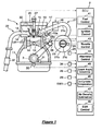
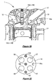
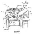
- Figure 1 shows an overview of an engine system of an internal combustion engine 1.
- the engine 1 is onboard of an automotive vehicle and drives wheels of the vehicle through a drive-train including a transmission, as is well known in the art.
- the engine 1 preferably is a direct injection spark ignition engine, although a port injection type spark ignition engine may be employed.
- the engine 1 comprises a cylinder head 10 and a cylinder block 11 to form a plurality of (e.g. four) cylinders 12A -12D therein, although only one cylinder is shown in Figure 1 .
- a piston 13 is arranged is inserted to the cylinder 12 to form or define a combustion chamber 14 and connected to a crankshaft 3, as is well known in the art.
- An engine control unit (ECU) 2 controls various actuators of the engine 1 based on various signals from sensors particularly detecting engine operating conditions.
- the ECU 2 is a microcomputer based controller which comprises a memory storing computer program and data, a microprocessor executing the computer program and data, and input and output (I/O) busses inputting and outputting the signals, as is well known in the art.
- I/O input and output
- a spark plug 15 is arranged preferably at or near the top of the combustion chamber with its electrode at least partly located in the combustion chamber 14.
- the spark plug 15 is made to spark by an ignition device 27 well known in the art, which is controlled by an ignition control section 42 of the ECU 2 so as to set proper ignition timing for each of the cylinders 12A-12D.
- a fuel supply system 16 includes a fuel injector 16a which is arranged at a side of the combustion chamber 14 on the cylinder head 10 to preferably directly inject fuel into the combustion chamber 14.
- the fuel supply system 16 preferably also includes high pressure fuel pump not shown.
- the fuel pump supplies fuel from a fuel tank through a fuel delivery pipe to the injector 16b with a higher pressure.
- the fuel control section 41 of the ECU 2 may control the pressure of the fuel pump for example between 3 and 13MPa.
- the fuel injector 16a includes therein a valve (preferably a needle valve) and a solenoid to drive the (needle) valve.
- the solenoid is exerted to open the (needle) valve for a time period substantially corresponding to a pulse width of a pulse signal input from the fuel control section 41 of the ECU 2. While the (needle) valve is at least partly open, fuel is injected substantially toward proximity of the electrode of the spark plug 15 in the combustion chamber 14.
- the fuel injector 16a preferably has a plurality of injection holes, and is of a so called multiple hole type.
- FIG. 1 shows an example of the valve driving mechanism.
- the intake valve 19 preferably is reciprocally actuated by a tappet 19a which particularly is arranged substantially above the valve stem.
- the tappet 19a is contacted and pushed by an intake cam 19b which is formed with and rotationally driven by an intake camshaft 191.
- the exhaust valve 20 preferably is reciprocally actuated by a tappet 20a which is contacted and pushed by an exhaust cam 20b formed with an exhaust cam shaft 201.
- the camshafts 191 and 201 are connected to and rotationally driven by the crankshaft 3 through a chain or belt, as is well known in the art.
- all of the four cylinders 12A through 12D have the same valves 19 and 20 associated with the camshafts 191 and 201.
- Engine cycles take place sequentially in the order of the first cylinder 12A, the third cylinder 12C, the fourth cylinder 12D and the second cylinder 12B (see Figure 3 for a physical arrangement of the cylinders within the cylinder block 11) with a phase difference of 180 degree crank angle (°CA), as is common in the four cycle four cylinder engines.
- °CA 180 degree crank angle
- variable valve mechanism 190 for the intake cam shaft 191.
- the variable valve mechanism 190 is controlled by a valve control section 49 of the ECU 2 to change or varying a phase of the intake camshaft 191 so that open and closing timing of the intake valve 19 thereby achieving variable valve timing (VVT) function.
- VVT variable valve timing
- the WT function preferably is only available for the intake valve 19, the exhaust valve 20 may be provided with it.
- variable valve lift (WL) function may be provided for either of the intake valve 19 and the exhaust valve 20 by a WL mechanism which may vary, preferably, substantially continuously a valve lift, preferably, from zero to a maximum stroke defined by a cam profile.
- valve driving mechanism and the variable valve mechanism for either of the intake valve 19 and the exhaust valve 20 may be substituted with an electromagnetic or electro-hydraulic valve drive mechanism or other valve mechanism which may open and close the valve free of correlation with a rotational angle or phase of the crankshaft 3.
- an intake passage 21 and an exhaust passage 22 are respectively connected to the intake ports 17 and the exhaust ports 18.
- the intake passage 21 preferably comprises a surge tank 21 a at its upstream side, branch passages 21 b communicating between the surge tank 21 a and the respective intake ports 17 and a common intake passage 21 c upstream of the surge tank 21 b.
- a throttle valve 23 is arranged in the common intake passage 21 c and actuated by an actuator 24, for example, an electric motor, which changes an opening of the throttle valve 23 according to a control signal computed by a throttle control section 43 of the ECU 2.
- a change of opening of the throttle valve 23 may correspond to an individual air amount or air flow within a particular cylinder, particularly just before a complete stop of the engine 1. That eventually may affect a stop position of the engine or a position of the piston 13 when the engine stops, as a result of a difference of the individual air amount within the individual cylinders.
- an airflow or air amount sensor 25 detecting intake airflow or air amount
- an intake air temperature sensor 29 detecting a temperature of the intake air
- an ambient pressure sensor SW1 detecting a pressure of the atmosphere upstream of the throttle valve 23
- an intake air pressure sensor 26 downstream of the throttle valve 23 all of which output signals to the ECU 2, while these sensors are not shown in Figure 3 , but only in Figure 1 .
- the catalyst 37 may comprise, preferably in its can or housing, a so called three way catalyst (TWC) which has higher purification ratios of HC, CO and NOx when an air fuel ratio of the exhaust gas is near the stoichiometry and has an oxygen storage capacity to adsorb oxygen in an oxygen excess atmosphere where an oxygen concentration in the exhaust gas is higher than the stoichiometry and releases the adsorbed oxygen to react it with HC, CO when the oxygen concentration is lower than the stoichiometry.
- TWC three way catalyst
- the catalyst is not limited to TWC, but it may be one having the oxygen storage capacity and, for example, may be a so called lean NOx catalyst which can purify NOx in an excess oxygen atmosphere.
- an exhaust gas recirculation (EGR) passage 38 which communicates between the intake passage 21 downstream of the throttle valve 23 and the exhaust passage 22 upstream of the catalyst converter 37 for re-circulating the exhaust gas to the engine 1.
- EGR exhaust gas recirculation
- the EGR passage 38 there is arranged an EGR valve 39 which is controlled by an EGR control section 48 of the ECU 2 to regulate an amount of the re-circulated exhaust gas.
- an alternator 28 which is (preferably connected through a belt to and) driven by the crankshaft 3 to generate electricity while the engine 1 is running.
- the alternator 28 has a regulator circuit 28a which adjusts an electric generation amount by adjusting a field current to a field coil of the alternator 28, as is known in the art.
- the regulator circuit 28a is controlled by a signal from an alternator control section 44 of the ECU 2 to adjust the field current.
- the alternator control section 44 computes the signal to the regulator circuit 28a based on various operating conditions such as electric load of the vehicle and a voltage of a battery onboard. Further it may change the load on the engine 1 by varying the field current of the alternator 28. As a result, it may help to stop the engine 1 at a desired position or prevent too much spin up of the engine 1 just after an engine start.
- a cam angle sensor 32 around a member or wheel which is affixed to and rotates with the exhaust camshaft 201 and has one tooth at its periphery.
- the cam angle sensor 32 outputs a signal to the ECU 2.
- The-cam angle signal preferably gives a falling or rising edge as a rotational reference signal once per rotation of the camshaft 191 or 201 or two rotations of the crankshaft 3 which is 720°CA.
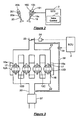
- crank angle sensors 30 and 31 which detect a rotation of the wheel or member (e.g.
- the ECU 2 may compute an engine speed N E preferably by counting number of edges of either of the rotational reference signal and the crank angle signal CA1 or CA2 per unit of time, although the crank angle signal is-more accurate because of more number of teeth the tooth wheel or member has.
- the ECU 2 may compute an angular position of the crankshaft 3 or a position of each of the pistons 13 in the first through fourth cylinders 12A through 12D based on the rotational reference signal and the crank angle signal CA1 or CA2 preferably by counting number of edges from the crank angle signal since a last edge of the rotational reference signal, as is known in the art.
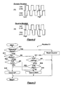
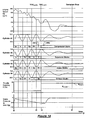
- a crank angle determination section 45 of the ECU 2 can compute a position of the piston 13, not only during normal rotation of the engine 1, but also when the engine 1 stops, reverses or repeats forward and reverse rotation, preferably using the two crank angle sensors 30 and 31. They are so arranged around the tooth wheel or member that the crank angle signals CA1 and CA2 have a phase difference, for example by a half of the pulse width, as shown in Figure 4 . Based on a difference between the crank angle signals CA1 and CA2 during a forward rotation of the crankshaft 2 shown in Figure 4(A) and during a reverse rotation in Figure 4(B) , the ECU 2 can determine a rotational direction of the crankshaft 2.
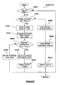
- a flowchart of Figure 5 shows a crank angle determination routine C run by the crank angle determination section 45 of the ECU 2.
- the routine proceeds to a step SP1 where it is determined whether a reference signal from the cam angle sensor 32 is detected or not. If it is detected that at the step SC1, the routine proceeds to a step SC2, where a crank angle counter CA in the crank angle determination section 45 is reset to be a specified (predetermined or predeterminable) value such as zero. If the reference signal is not detected at the step SC1, the routine proceeds to a step SC3 where it is determined whether a rising edge of the crank angle signal CA1 is detected or not. If a rising edge of CA1 is detected (YES) at the step SC3, the routine proceeds to a step SC4.
- crank angle signal CA2 is low or not. If the CA2 is low (YES) at the step SC4, it means that the crankshaft 3 is in a forward rotation as can be seen in Figure 4(A) . Then, the routine proceeds to a step SC5 where the counter CA that is initially zero at the step SC2 is counted up by one. On the other hand, if the CA2 is high (NO) at the step SC4, it means that the crankshaft 3 is in a reverse rotation as can be seen in Figure 4(B) . In this case, the routine proceeds to a step SC6 and counts down the counter CA by one.
- the routine proceeds to a step PP7 and determines whether a falling edge of CA1 is detected. If it is not detected, the routine returns to the step SP3 and waits for a rising edge of CA1. If the falling edge of CA1 is detected, the routine proceeds to a step SP8 and determines whether or not the signal CA2 is high. If the CA2 is high (YES) at the step SP8, it means that the crankshaft 3 is in a forward rotation as can be seen in Figure 4(A) . Then the routine proceeds to the step SP5 and counts up the counter CA by one. If the CA2 is low (NO) at the step SP8, it means that the crankshaft 3 is in a reverse rotation as can be seen in Figure 4(B) and the routine proceeds to the step SP6 and counts up the counter CA by one.
- the routine proceeds to a step SP9 and reads out a count number from the counter CA.
- the count number shows number of rising and falling edges of the crank angle signal CA1 which corresponds to the number of tooth of the tooth wheel of the crankshaft 3 from the reference rotational position of the engine 1 that is derived from the reference signal from the cam angle sensor 32.
- the count number shows an absolute angular position CA of the crankshaft 3. Consequently, an angular position of the crankshaft 3 or a piston position can be determined even after repeated back and forth movements of the crankshaft 3 just before the engine completely stops.
- an engine temperature sensor 33 which detects a temperature of the engine 1 (preferably by detecting a temperature of an engine coolant in or from the cylinder block 11) and a driver operation sensor 34 which detects operations of a vehicle driver such as a position of an accelerator pedal, a position of a brake pedal or a gear position or shift range of the vehicle transmission.
- a driver operation sensor 34 which detects operations of a vehicle driver such as a position of an accelerator pedal, a position of a brake pedal or a gear position or shift range of the vehicle transmission.
- an in-cylinder temperature estimation section 46 which estimates air temperatures of the respective cylinders 12A-12D based on an engine temperature detected by the engine temperature sensor 33, an intake air temperature detected by the intake air temperature sensor 29 and others, using a map predetermined-through an experiment. Particularly in this embodiment, when restarting the engine 1, the section 46 consider a time period of the engine 1 stopping for an in-cylinder temperature estimation at the time of restarting the engine 1.
- an air density estimation or determination section 47 which estimates or determines an air density of the atmosphere preferably based on intake air temperature sensor 29 and the ambient air pressure sensor SW1.
- the estimated or determined air density may be used for determining engine control parameters at the time of restarting the engine 1.
- the crankshaft 3 in the reverse rotation raises the piston 13 of a cylinder which has stopped in its expansion stroke (hereafter referred to as "expansion stroke cylinder) and the number two cylinder (cylinder #3) in the case of Figure 22 .
- the piston 13 of the expansion stroke cylinder compresses the air inside and receives a counterforce from the compressed air. This counterforce may help to reverse the rotation of the crankshaft 3.
- fuel is injected into the expansion stroke cylinder, and then around the rotational reversal, a spark is made in the expansion stroke cylinder, thereby initiating combustion. This combustion accelerates the forward rotation of the crankshaft 2.
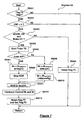
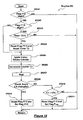
- the ECU 2 processes the engine stop control by running a computer program, which is stored in its memory, particularly control routines illustrated by the flowcharts of Figures 6 through 12 .
- the engine stop control is comprised of first through seventh stages or seven control routines S1 through S7.
- the first stage in particular is a preliminary stage of the engine stop control.
- a flag F1 is High or not.
- the flag F1 is set High, when it is determined possible to initiate the first stage of the engine stop control or if several predetermined or predeterminable conditions are met.
- the conditions preferably include that a speed of the vehicle is faster than a reference (predetermined or predeterminable) speed such as about 10 km/h, that a steering angle of the vehicle is less than a reference (predetermined or predeterminable) angle, that a voltage of a vehicle battery is more than a reference (predetermined or predeterminable) voltage and/or that an air conditioner of the vehicle is OFF.
- the routine determines at a step SS102 whether the accelerator pedal is fully released and the brake pedal is depressed more than a reference (predetermined or predeterminable) level or not from the driver operation sensor 34. If it is preferably determined that the accelerator pedal is fully released and the brake pedal is depressed more than the reference level (YES) at the step SS102, which means that the engine 1 is in an engine deceleration condition and not in a coasting condition and that the vehicle is more likely to stop, the routine proceeds to a step SS103, and otherwise returns.
- a reference predetermined or predeterminable
- the routine determines whether an engine speed N E is higher than a first reference (predetermined or predeterminable) engine speed for fuel cut (N FC1 ), such as about 1100 rpm. If it is determined that the engine speed N E is higher than the first reference value N FC1 (YES) at the step SS103, it means the engine speed is relatively high in the deceleration condition and it is beneficial to cut off the fuel supply to the engine for a fuel economy improvement, and the routine proceeds to a step SS104 and stops the fuel supply as is known in the art, then returns.
- a first reference predetermined or predeterminable engine speed for fuel cut
- the routine proceeds to a step SS105 and determines whether the engine speed N E is lower than a second reference (predetermined or predeterminable) engine speed for fuel cut (N FC2 ), such as about 900 rpm, or not. If it is determined that the engine speed N E is higher than the second reference speed N FC2 (YES) at the step SS105, the routine proceeds to a step SS106 and determines whether the fuel is already cut off or not.
- a second reference (predetermined or predeterminable) engine speed for fuel cut such as about 900 rpm
- the routines proceeds to the step SS104 and continues to stop the fuel supply, while if NO at the step SS106, the routine returns because a substantial fuel saving benefit can not be expected. If it is determined at the step SS105 that the engine speed Ne is lower than the second reference speed N FC2 , the routine does not cut off the fuel and proceeds to a step SS108.
- the routine determines whether a target air fuel ratio for the engine 1 is set substantially leaner than the stoichiometric air fuel ratio or not. If it is determined that the target air fuel ratio is leaner than the stoichiometry (YES) at the step SS108, the routine proceeds to a step SS109 and sets a first target speed of the engine 1 (N TARGET1 ) substantially higher than a normal idle speed (N IDLE ), such as about 650 rpm. The first target speed in this case may be for example -about 750 rpm.
- the routine proceeds to a step SS110 and sets a second target speed N TARGET2 which is higher than the first target speed N TARGET1 and may be for example about 800 rpm.
- the routine proceeds to a step SS111 and initiates a (preferably feed back) control of the target engine speed adjusting the throttle opening K, the fuel injection amount FP or the ignition timing.
- the routine proceeds to a step SS112 and sets the flag F1 to be High and preferably a flag F2 to be Low.
- the flag F2 indicates readiness of executing the second stage of the engine stop control.
- the engine idle speed is set higher than the normal idle speed at the step-SS109 or SS110 and it is maintained at the step SS111.
- the engine idle speed is relatively high and stable, so that more precise engine stop control can be made. Also it is not necessary to increase the engine speed from the normal speed for the more stable engine rotation after the vehicle really stops and requires the engine stop control, thereby reducing some discomfort of vehicle occupants and longer time period of the engine stop control which the increase of the engine speed for the longer gap may cause.
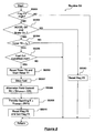
- the routine determines whether the flag F2 is High or not. If it is OFF, the routine returns and waits for the flag F2 high. If it is ON, it proceeds to a step SS202 and determines whether or not a vehicle speed VSP is zero or the vehicle is completely stopped. If it is NO at the step SS202, the engine stop is not required yet, so the routine S2 returns.
- the routine S2 proceeds to a step SS203 and determines whether or not the accelerator pedal is fully released and the brake pedal is depressed more than a reference level from the driver operation sensor 34. If it is NO at the step SS203, that means the engine stop is not desired any more, and the routine proceeds to a step SS204 and resets the flag F2 to be Low so that the ECU 2 takes the normal engine control. Then the routine returns. If it is YES at the step SS204, the routine S2 proceeds to a step SS205 and starts a timer T0.
- the routine proceeds to a step SS206 and determines whether or not a target air fuel ratio for the engine 1 is set substantially leaner than the stoichiometric air fuel ratio. If it is determined that the target air fuel ratio is leaner than the stoichiometry (YES) at the step SS206, the routine proceeds to a step SS207 and sets a third target speed N TARGET3 which is a little bit of higher than the first target idle speed N TARGET1 and may be for example about 810 rpm. Then the routine proceeds to a step S208 and the EGR control section of the ECU2 controls the EGR valve 39 for improving scavenging effect in the cylinders 12A through 12D.
- the routine proceeds-to a step SS209 and sets a fourth target speed N TARGET4 which is even higher than the second target speed N TARGET2 and may be for example about 860 rpm. Then it proceeds to a step SS210 and sets a target intake air pressure Bt TARGET1 which is a relatively higher pressure even for the given fourth target engine speed N TARGET4 and may be for example about -400 mm Hg.
- the ignition timing is retarded preferably heavily, so that the exhaust gas temperature becomes higher and activity of the catalyst 37 may be maintained or it may be regenerated if it is a NOx catalyst due to the greater amount of the stoichiometric or rich exhaust gas.
- the routine S2 proceeds to a step SS211 and the ECU 2 controls the transmission to be in a neutral range to make a no-load condition. Then, the routine proceeds to a step SS212 and the ECU 2 initiates (preferably feedback) control of the fuel injection amount FP, the ignition timing and the throttle opening K to meet to the target values set at the steps SS207 or SS209 and SS210. Finally at a step S213, the routine resets the flag F2 to be Low and preferably sets a flag F3 to be High, then it returns. The flag F3 indicates a readiness to stop the fuel for finally stopping the engine 1.
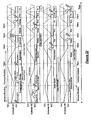
- the engine speed Ne starts to increase from the first to third or second to fourth target speeds by the feedback control initiated at the step SS210.
- the engine speed is substantially at to the target speed (N TARGET4 in Figure 13 ).
- the smaller gap between the two target speeds set may substantially prevent the discomfort of the vehicle occupants described above.
- the routine determines whether the flag F3 is High or Low. If it is Low, the routine S3 returns and waits for the flag F3 High. If it is ON, it proceeds to a step-SS302 and determines whether the-accelerator pedal is fully released and the brake pedal is depressed more than a reference level or not from the driver operation sensor 34. If it is NO at the step SS302, which means that the engine stop is not desired any more, and the routine proceeds to a step SS303 and resets the flag F3 to be OFF so that the ECU 2 takes the normal engine control. Then the routine returns.
- the routine proceeds to a step SS304 and determines whether or not the timer T0 exceeds a predetermined or predeterminable threshold value t A , which may be for example about one second. If it is determined the timer T0 exceeds the threshold value (YES) at the step SS304, the routine proceeds to a step SS305, and otherwise it returns and waits for the count up of the timer T0. At the step SS305 the routine determines whether a condition for cutting off the fuel is met or not.
- the fuel cut condition may include a substantially stable engine speed Ne at the target speed N TARET3 or N TARGET4 and a substantially stable boost pressure Bt at the target intake air pressure P1.
- step SS305 If it is YES at the step SS305, which means that the predetermined or predeterminable time period t A has passed since the time t0 and it is now time t1 in Figure 12 , the routine proceeds to a step SS306 and resets the timer T0 and starts another timer T1. Otherwise, the routine returns and waits for the fuel cut condition to be met.
- the routine proceeds to a step SS307 and stops the fuel supply. Then it proceeds to a step SS308 and sets a target value Ge TARGET1 of a field current Ge of the alternator 28 to be 0A, so that the alternator control section 44 controls the regulator circuit 28a to shut off the field current to the alternator 28, thereby stopping the electric generation.
- step SS308 the routine proceeds to a step SS309 and sets a target throttle valve opening K TARGET1 to be for example about 80%, so that the throttle control section 43 of the ECU 2 controls the throttle actuator 24 to open the throttle valve 23 up to about 80%, thereby increasing the intake air pressure Bt as shown in Figures 13 and 14 between the time t1 and time t2.
- step SS310 the routine resets the flag F3 to be Low and sets a flag F4 to be High. The flag F4 indicates that the fuel supply is already stopped but the engine 1 is still running.
- the routine determines whether the flag F4 is High or Low. If it is Low, the routine returns and waits for the flag F4 to be High. If it is High, it proceeds to a step SS402 and determines whether the timer T1 counts exceeding a reference (predetermined or predeterminable) value t B , which substantially corresponds to a time period of one engine cycle or two crankshaft rotations or 720°CA, as can be seen in Figure 13 between time t1 and t2.
- the value t B may be, for example, about 32 ms, given that the engine speed is now about 810 rpm as set at the step SS207 of the second routine.
- the routine proceeds to a step SS403 and stops the ignition because it is not needed any more. If it is NO at the step SS402, the routine returns and waits for the count up of the timer T1. After the step SS403, the routine proceeds to a step SS404 and determines whether the engine speed Ne is lower than a first reference (predetermined or predeterminable) speed N 1 .
- the reference speed N 1 is set lower than the third target speed N TARGET3 and/or the fourth target speed N TARGET4 which are respectively set at the steps SS208 and SS209 of the second routine and may be for example about 760 rpm. If it is determined the engine speed Ne is lower than the reference speed N 1 at the step SS404, which means that the engine speed has started falling, as shown in Figures 13 and 14 at time t2, the routine S4 proceeds to a step SS405 and sets a target throttle opening K TARGET2 to be zero so that the throttle control section 43 of the ECU 2 controls the throttle actuator 24 to substantially fully close the throttle valve 23.
- the routine proceeds to a step SS406 and sets a target generated electric current Ge TARGET2 in accordance to a target field current map or relationship or table M1 stored in the ECU 2.
- the map or relationship or table M1 sets the target generated electric current Ge TARGET2 versus the engine speed Ne so that the Ge TARGET2 is set about 60A at about 540 rpm or greater and set gradually falling to substantially zero at about 460 rpm. Based on the set target generated current Ge TARGET2 , the alternator control section 44 of the ECU 2 controls the regulator circuit 28a of the alternator 28.
- routine S4 proceeds to a step SS407 and determines whether the engine speed Ne is lower than a second reference (predetermined or predeterminable) speed N 2 , which is (preferably significantly) lower than the first reference speed N 1 .
- a second reference speed N 2 is set lower than a speed at which the engine 1 or the crankshaft 3 reaches a second last top dead center before the complete stopping (TDC LAST2 ) and may be for example about 400 rpm.
- step S407 If it is determined at the step S407 that the engine speed Ne is lower than the second reference speed N 2 , which means that the engine 1 reaches the second last top dead center TDC LAST2 , as shown in Figure 14 at the time t3, the routine proceeds to a step SS408, and otherwise it returns and waits for the engine speed Ne falling to N 2 .
- the routine S4 stores the engine speed Ne determined at the previous step SR407 as a value N 2A and an air intake pressure Bt detected by the intake air pressure sensor 25 in the memory of the ECU 2 as a value Bt 2 for a later use, specifically at the sixth stage of the engine stop control. Then the routine proceeds to a step SS409 and resets the timer T1 to be zero. Next at a step SS410, it resets the flag F4 to be Low and preferably sets another flag F5 to be High, then returns. The flag F5 indicates that the engine 1 reaches the second last top dead center or the time t3 in Figure 14 .
- the routine determines whether the flag F5 is High or Low. If it is Low, the routine returns and waits for the flag F5 to be High. If it is High, it proceeds to a step SS502 and determines whether an air density ⁇ computed by the air density estimation section 47 of the ECU 2 is greater than a reference (predetermined or predeterminable) density ⁇ 1 or not.
- the reference density ⁇ 1 may be for example about 1.08kg/m 3 .
- the routine proceeds to a step SS503 and determines an amount of fuel (FP 1 ) for restarting the engine to be injected into a cylinder which is now in its intake stroke and the cylinder #1 in Figure 14 .
- the fuel amount FP 1 is determined based on the actual engine speed N 2A at the second last top dead center TDC LAST2 stored at the step SS408 of the fourth stage of the engine stop control or at the time t3, so that the fuel amount FP 1 is greater as the speed N 2A is greater, thereby more effectively utilizing the intake airflow during the intake stroke for the evaporation and atomization of fuel to be injected.
- the cylinder #1 which is in its intake stroke at the step SS503 or between the times t3 and t4 is supposed to be in its compression stroke when the engine 1 completely stops, as shown in Figure 14 after the time t4, so that in this case the cylinder #1 is a compression stroke cylinder described above. Therefore, the injected fuel is trapped in the cylinder 12 and then substantially is evaporated and atomized, making a substantially homogeneous mixture of air and fuel within the cylinder #1 during the engine stop. Also, it cools the temperature and decreases the pressure inside of the combustion chamber 14.
- routine S5 proceeds to a step SS504 and the fuel control section 41 of the ECU 2 controls the fuel supply system 16 to inject fuel of the amount FP 1 into the cylinder #1 in Figure 14 .
- routine S5 preferably sets a flag F5f to be High for later use at the time of restarting the engine.
- the routine S5 proceeds to a step SS505 and determines whether the engine speed Ne is lower than a third reference (predetermined or predeterminable) speed N 3 , which is significantly lower than the second reference speed N 2 and may be for example about 260 rpm.
- the routine proceeds to a step SS506, and otherwise it returns and waits for the engine speed Ne falling to N 3 .
- the routine resets the flag F5 to be Low and sets another flag F6 to be High, then returns.
- the flag F6 indicates that the engine 1 reaches the last top dead center or the time t4 in Figure 14 .
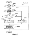
- the sixth stage of the engine stop control will now be described with reference to a flow chart of Figure 11 which illustrates the sixth control routine S6.
- the routine determines whether the flag F6 is High or Low. If it is Low, the routine returns and waits for the flag F6 to be High.
- step SS602 determines whether or not the engine speed N 2A , which is a speed at the second last top dead center TDC LAST2 and stored in the memory of the ECU 2 at the step SS408 of the routine R4, is higher than a fourth reference (predetermined or predeterminable) speed N 4 , which is lower than the third reference speed N 3 and may be for example about 200 rpm which is lower than the third reference speed N 3 by about 60 rpm.
- the routine S6 proceeds to a step SS603 and determines whether or not the intake air pressure Bt 2 at the second last top dead center TDC LAST2 which is stored at the step SS408 of the fourth stage of the engine stop control and detected at the time t3, is less than a reference pressure Bt 2REF such as about -200 mm Hg.
- That stop position may be within a preferable range R of stop position for the engine restarting, which will be described with greater detail below with reference to Figure 15 and may be between about 100 and about 120°CA from the bottom dead center of a cylinder which is in its compression stroke at the time of complete stop. So, in this case, the throttle valve 23 needs to be positioned just for the restarting. Then, the routine S6 proceeds to a step SS604 and sets a throttle opening K during stopping K to be a value K STOP1 which may be for example about 5% so that the throttle control section 43 of the ECU 2 controls the throttle actuator 24 to slightly open the throttle valve 23.
- the piston 13 in the cylinder #1 may finally stop at about 100°CA or closer to the bottom dead center which is out of the preferable stop range R in Figure 15 . Therefore, amount of intake air, which is now inducted into the cylinder #4 that is now in its intake stroke, is increased by widely opening the throttle valve 23, so as to reduce the resistance of the airflow and the decrease of the rotational inertia caused by the airflow resistance, thereby stopping the piston 13 in the cylinder #1 within the preferable stop range R.
- routine S6 proceeds to a step SS605 and sets a target throttle valve opening K during the engine stop to be a value K STOP2 which may be for example about 80%, so that the throttle control section 43 of the ECU 2 controls the throttle actuator 24 to open the throttle valve 23 up to about 80%.
- K STOP2 which may be for example about 80%
- routines SS604 and SS605 the routine proceeds to a step SS606 and resets the flag F6 to be Low and another flag F7 to be High.
- the flag F7 indicates that the engine does not make any continuous rotation but oscillates in rotation.
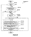
- the routine determines whether the flag F7 is High or Low. If it is Low, the routine returns and waits for the flag F7 to be High. If it is High, the routine S7 proceeds to a step SS702 and estimates a final engine stop position CA E_STOP , more particularly a final position of the piston 13 in the cylinder #1 which is now in its compression stroke in the case of Figure 14 .
- the crank angle determination section 45 of the ECU 2 continuously monitors the absolute position CA of the crankshaft 3 at the step SP9 in the crank angle determination routine C1 in Figure 5 . Based on the change of the absolute crankshaft position CA, the final stop position CA E_STOP is estimated or determined.
- the routine S7 proceeds to a step SS703 and determines whether or not the estimated or determined stop position CA E_STOP is within the preferred stop range R shown in Figure 15 . If it is YES at the step SS703, nothing is supposedly to be done, so that the routine S7 proceeds to a step SS704 and determines whether or not the crankshaft 3 completely stops based on the change of the absolute crankshaft position CA and waits for the complete stop.
- the routine S7 proceeds to a step SS705 and determines an amount of fuel (FP2) for restarting the engine 1 to be additionally injected into a cylinder which is the cylinder #1 in Figure 14 .
- the fuel amount FP2 is determined based on the estimated stop position CA E_STOP so that the amount is greater as the CA E_STOP is farther away from the preferred range R or the cylinder #1 is supposed to stop closer to its bottom dead center.
- the additional fuel decreases the temperature and pressure within the cylinder #1 particularly through the evaporative latent heat, thereby making it more likely to stop the piston 13 in the cylinder #1 within the preferred stop range R.
- the routine S7 proceeds to a step SS706 and the fuel control section 41 of the ECU 2 controls the fuel supply system 16 to inject fuel of the amount FP2 into the cylinder #1 in Figure 14 .
- the routine F7 proceeds to the step SS704, and determines the engine 1 completely stops or not, as described above.
- routine F7 proceeds to a step SS707 and starts a timer T2, which indicates the engine 1 is being stopped by the idle stop control. Then, it proceeds to a step SS708 and the ECU 2 controls the transmission to be shifted from the neutral range to a drive range for the engine restart and the following vehicle launch. Then, it proceeds to a step SS709 and reset the flag F7 to be Low, so that the engine stop control is completed.
- the engine 1 is now stopped within the preferred stop range R shown in Figure 1 : 5 .
- the cylinder #1 is now in its compression stroke (therefore, hereafter referred to as compression stroke cylinder)
- the cylinder #2 is in its expansion stroke (therefore, hereafter referred to as expansion stroke cylinder) and their rotational phases are offset by 180°CA, as shown in Figure 15(A) .
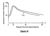
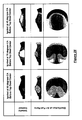
- a temperature inside of the cylinder is predicted to change.
- flow of engine coolant may stop as well, and it causes the temperature inside of the cylinder to rapidly rise and the pressure inside to rise as well. This pressure increase may help the air inside go out of the cylinder.
- the expansion stroke cylinder has more air mass than the compression stroke cylinder does.
- the air in the compression stroke cylinder is used for temporary reverse rotation to compress the air in the expansion stroke cylinder, while the air in the expansion stroke cylinder is used for a start of a continuous rotation.
- the expansion stroke cylinder needs more air than the compression stroke cylinder does, while excessively small amount of the air in the compression stroke cylinder can not generate energy to rotate the crankshaft 3 in reverse. Therefore, the preferred range R of the stop position of the compression stroke cylinder preferably is set between about 100 and about 120 °CA from its bottom dead center, as shown in Figure 15 .
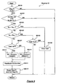
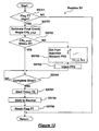
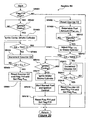
- the ECU 2 processes the engine restart control by running a computer program stored therein, and comprised of first through fifth stages or four control routines R1 through R5 illustrated by the flowcharts of Figures 17 through 21 .
- the engine restart control at first initiates the combustion in the compression stroke cylinder (or the cylinder #1 in the diagrams of Figures 14 and 22 ) to rotate the crankshaft 3 in reverse and compress air in a cylinder which stops in its expansion stroke (therefore, hereafter referred to as expansion stroke cylinder) and is the cylinder #2 in Figures 14 and 22 , and then initiates the combustion in the expansion stroke cylinder and the forward rotation of the crankshaft 3.
- the routine R1 After a start of the first stage or the routine R1 shown in Figure 17 , it determines at a step SR101 whether a flag F11 is High or Low.
- the flag F11 is set High when there is at least one of conditions to restart the engine 1, which include that the accelerator pedal is depressed, that a voltage of the vehicle battery is less than the reference voltage and/or that the air condition of the vehicle is ON. If it is determined that the flag F11 is High at the step SR101, the routine R1 proceeds to a step SR102, or otherwise it returns and waits for the flag F11 to be High.
- the valve control section 49 of the ECU 2 controls the variable valve timing mechanism 190 so that the intake valve close timing is delayed to, for example, about 100°CA after top dead center.
- the intake valve 19 of the compression cylinder (#1) will be slightly opened at the late stage of the reverse rotation and the early stage of the reverse rotation, as shown in Figure 22 , so that some of combusted gas is exchanged with fresh air in the intake passage 21.
- the routine R1 proceeds to a step SR103 and determines whether the flag F5f is High or not. If the flag F5f is High, the fuel FP1 was injected to the compression stroke cylinder or the cylinder #1 in Figure 14 at the step SS503 of the fifth stage of the engine stop control shown in Figure 10 . If it is YES at the step SR103, the routine R1 proceeds to a step SR 104 and resets the flag F5f to be Low. Then, it proceeds to a step SR105 and determines whether the timer T2 counts exceeding a reference value t c . The timer T2 was started at the step SS706 of the engine stop control at the time of the complete stop of the engine 1.
- the reference value t c preferably is set substantially corresponding to a time period for which the inside of the compression stroke cylinder gets diluted too much to achieve the desired combustion status.
- the dilution in the cylinder may be caused by the communication of the air in the cylinder to the outside described above.
- step SR105 If it is determined that the timer T1 exceeds the predetermined value t c (YES) at the step SR105, it is considered that fuel needs to be injected to the compression stroke cylinder due to the dilution in the cylinder. Also if it is determined that the flag F5f is Low (NO) at the step SR103, it is considered that fuel needs to be injected to the compression stroke cylinder, because there may be no fuel in the cylinder.
- the routine R1 proceeds to a step SR106. Since the engine rotation during the engine stop control is adjusted to stop the engine 1 or the crankshaft 3 within the range R of Figure 15 , the decision of the step SR106 is not likely to be YES, but even if it is smaller, the possibility of stopping outside of the range R can not be ignored. Therefore, the routine R1 determines from a crank angle CA STOP when the engine stops, which is derived from the routine shown in Figure 5 and stored in the memory of the ECU 2, whether or not the compression stroke cylinder (cylinder #1 in Figures 14 and 22 ) is positioned at about 100°CA or farther from its bottom dead center. That crank angle about 100°CA of is the lower end of the preferred stop range R, as described above.
- a target air fuel ratio AF CMP_CYL1 is set in accordance with a map M11 which defines the air fuel ratio as a function of the stop crank angle CA STOP so that the air fuel ratio AF CMP_CYL1 is richer as the crank angle CA STOP is closer to the top dead center of the compression stroke cylinder.
- the routine R1 proceeds to a step SR108 and sets a target air fuel ratio AF CMP_CYL1 to be lean of the stoichiometry (A>1) so as to prevent the later combustion from generating too much energy for the reverse rotation and the piston of the expansion stroke cylinder from exceeding the top dead center.
- the lean target air fuel ratio is set in accordance with a map or relationship or table M12 which also defines the air fuel ratio as a function of the crank angle CA STOP (or gives values for the air fuel ratio for different values of the crank angle CA STOP ) in the substantially same manner as the map M11 does.
- the routine R2 proceeds to a step SR109 and the in-cylinder temperature estimation or determination section 46 estimates or determines a temperature T CMP_CYL preferably based on an engine coolant temperature from the engine temperature sensor 33 and/or the count of the timer T2 which corresponding to elapsed time from the complete engine stop, and others in accordance with a map or mathematical formula or table (e.g. which is determined from a prior experiment and generally in line with the graph of Figure 16 ). Then the routine R1 proceeds to a step SR110 and determines a fuel injection amount FP CMP_CYL1 .
- the air amount AM CMP_CYL is estimated or determined preferably based on a volume in the compression stroke cylinder derived from the crank angle CA STOP , air density ⁇ derived from the air density estimation section 47 of the ECU 2 and/or the temperature T CMP-CYL in the compression stroke cylinder.
- the routine R1 proceeds to a step SR110 and sets a flag F11f to be High and starts a timer T3 and the fuel control section 41 of the ECU 2 controls the fuel supply system 16 to inject fuel of the computed amount FP CMP_CYL1 into the compression stroke cylinder.
- the routine R1 proceeds to a step SR112 where it stores the current count value of the timer T2 into the memory of the ECU 2 for its later use, resets the timer T2 to be zero, resets the flag F11 to be Low and sets another flag F12 to be High.
- the flag F12 indicates the compression stroke cylinder is ready for ignition.
- the routine determines whether the flag F12 is High or Low. If it is Low, the routine returns and waits for the flag F12 to be High. If it is ON, it proceeds to a step SR202 and determines whether the flag F12f is High or not. If the flag F11f is High, the fuel FP CMP_CYL1 is injected at the first stage of the restart control as described above and illustrated in Figure 16 at the step SR109, then the routine R2 proceeds to a step SR203 and determines whether the timer T3 counts exceeding a reference (predetermined or predeterminable) value t F or not.
- the value t F is preset corresponding to a time period for which the fuel injected at the first stage of the restart evaporates. If it is determined that the timer T3 count exceeds the value t F (YES) at the step SR203, this particularly may mean that it is ready to ignite the fuel in the compression stroke cylinder, then the routine R2 proceeds to a step SR204. On the other hand, if it is NO at the step SR203, it is not ready to ignite and the routine R2 returns and waits for the timer T3 counts up to the value t F . At the step SR204, the routine R2 resets the flag F11f to be Low and the timer T3 to be zero.
- the routine R2 proceeds to a step SR205 and the ignition control section 42 of the ECU 2 controls the ignition system 27 to cause the spark plug 15 to make a spark in the compression stroke cylinder (cylinder #1 in Figure 22 ). Then, the routine R2 proceeds to step SR206 and increments a counter C1 by one, and waits at a step SR207 for the counter C1 counting up every predetermined counts which correspond to a predetermined time period, such as about 50 ms. After the count up of the counter C1, the routine R2 proceeds to a step SR208 and determines whether or not a crankshaft angle CA is changed.
- the routine R2 determines at a step 210 whether or not the counter C1 counts more than a reference count number C F1 .
- step SR210 If it is YES at the step SR210, it is considered that too many attempts to ignite the air and fuel mixture in the compression stroke cylinder are made, and the routine proceeds to a step SR211 and resets the counter C1 to be zero, resets the flag F12 to be OFF and sets a flag F FAIL . On the other hand, if it is NO at the step SR210, the routine R2 returns and repeats ignition attempts at the step SR205 until the crank angle change is detected at the step SR208.
- the routine determines whether the flag F13 is High or Low. If it is Low, the routine returns and waits for the flag F13 to be High. If the flag F13 is High at the step SR301, the routine R3 proceeds to a step SR302 and estimates or determines a current temperature T EXP_CYL in the expansion stroke cylinder.
- the in-cylinder temperature estimation or determination preferably may be made in the same manner as is done for the temperature T COM_CYL of the expansion stroke cylinder at the step SR108 of the first routine R1 or the first stage of the restart control.
- the routine proceeds to a step SR303 and determines an air amount in the expansion stroke cylinder (AM EXP_CYL ) based on the estimated in-cylinder temperature T EXP_CYL and a cylinder volume.
- the cylinder volume may be computed based on the crank angle CA STOP when the engine stops, which is derived from the routine shown in Figure 5 and stored in the memory of the ECU 2.
- the second half of the fuel amount FP EXP_CYL2 is set larger as the stop crank angle CA STOP indicates the expansion stroke cylinder stopped closer to its bottom dead center, because more air exists in the cylinder and compression counterforce will be higher so that the evaporative latent heat from the second half fuel preferably will be necessary to reduce the compression counterforce. Also, the second half of the fuel amount FP EXP_CYL2 is set larger as the in-cylinder temperature T EXP_CYL is higher, because it promotes to evaporate the injected fuel to reduce need for the earlier injection and later injection promotes rapid combustion intended for the expansion stroke cylinder. Then, the routine R3 proceeds to a step SR306 and determines second fuel injection timing to the expansion stroke cylinder.
- the second fuel injection timing is set based on the stop crank angle CA STOP and the estimated or determined in-cylinder temperature T EXP_CYL so that evaporative latent heat of the second half of the fuel helps to compress the air in the expansion stroke cylinder in the reverse movement and the injected fuel can be evaporated enough until the ignition.
- the routine R3 proceeds to a step SR307 and determines timing of an ignition for the expansion stroke cylinder or a delay time period of the ignition from the second injection timing so that the injected fuel evaporates enough.
- the routine proceeds to a step SR308 and determines a fuel injection amount for the compression stroke cylinder after a reversal of rotation (FP CMP_CYL2 ).
- FP CMP_CYL2 determines a fuel injection amount for the compression stroke cylinder after a reversal of rotation
- the fuel amount FP CMP_CYL2 is set so that the air fuel ratio in the compression stroke cylinder after the reversal is richer than the combustible limit (7.0 or 8.0 for a gasoline engine) and may be for example about 6.0, thereby preventing self-ignition of the air fuel mixture therein and counterforce caused by it.
- amount or flow of fresh air inducted into the compression stroke cylinder during the opening of the intake stroke cylinder is estimated based on the stop crank angle CA STOP , intake air temperature detected by the intake air temperature sensor 25 and an engine coolant temperature detected by the engine temperature sensor 33.
- the fuel amount FP CMP_CYL2 is determined based on the intake air amount AM CMP_IN , the air amount AM CMP_CYL estimated at the step SR109 and any of the fuel amounts FP 1 , FP 2 and FP CMP_CYL1 injected into the compression stroke cylinder.
- the fuel amount FP CMP_CYL2 is set so that the air fuel ratio in the compression stroke cylinder after the reversal is richer than the stoichiometry and combustible by spark ignition.
- the fuel control section 41 of the ECU 2 controls the fuel supply system 16 to inject fuel of the first second half amount (FP EXP-CYL2 ) which is determined at the step SR305 into the expansion stroke cylinder.
- the routine R3 proceeds to a step SR312 and waits for the ignition timing which is determined at the step SR307.
- the ignition control section 42 of the ECU 2 controls the ignition system 27 to cause the spark plug 15 to make a spark in the expansion stroke cylinder.
- the routine R3 waits at a step SR314 for injection timing of fuel of the amount FP CMP_CYL2 determined at the step SR308. This injection timing is after the reversal of the rotation and before the compression stroke reaches its top dead center. Then, at the injection timing, the routine R3 proceeds to a step SR315 and the fuel control section 41 of the ECU 2 controls the fuel supply system 16 to inject fuel of the amount FP CMP_CYL2 which is determined at the step SR308 into the compression stroke cylinder. Finally, the routine R3 proceeds to a step SR316 and resets the flag F13 to be Low and preferably sets another flag F14 to be High. The flag F14 indicates the engine 1 has started a forward rotation.
- the routine determines whether the flag F14 is High or Low. If it is Low, the routine returns and waits for the flag F14 to be High. If it is High, it proceeds to a step SR402 and waits for ignition timing of the compression stroke cylinder.
- This timing is set just (for example about a couple of degrees crank angle) before a top dead center of the compression stroke cylinder or a first top dead center of the forward rotation (TDC1), so that the ignited air fuel mixture generates energy after the first top dead center TDC1, as shown in Figure 22 , thereby accelerating the forward rotation, if combustible gas exists in the compression stroke cylinder even after the combustion for the reverse rotation.
- the routine R4 proceeds to a step SR403 and the ignition control section 42 of the ECU 2 controls the ignition system 27 to cause the spark plug 15 to make a spark in the compression stroke cylinder.
- the routine R4 proceeds to a step SR404 and determines whether of not the crank angle CA indicates the engine 1 or the crankshaft 3 has passed the first top dead center TDC1. If it is NO, the routine R4 proceeds to a step SR405 and increments a counter C2 by one. Then, it proceeds to a step SR406 and determines whether or not the counter C2 exceeds a reference value C F2 . If it is determined that the counter C2 exceeds the reference value C F2 (YES) at the step SR407, it indicates that the first top dead center could not be passed and this engine restart operation is failed.
- routine R4 proceeds to a step SR407 and resets the counter C2 to be zero, resets the flag F14 to be Low and sets the fail flag F FAIL to be High. If it is NO at the step SR406, the step SR404 is repeated until it determines the first top dead center TDC1 is passed.
- the routine R4 proceeds to a step SR408 and resets the counter C2 to be zero. Then, it proceeds to a step SR409 and determines amount of fuel to be injected into a cylinder which was stopped in its intake stroke (FP INT_CYL ). That cylinder is the cylinder #3 in the case of Figures 14 and 22 and hereafter referred to as intake stroke cylinder.
- the fuel amount FP INT_CYL is determined based on air amount in the intake stroke cylinder and an air fuel ratio AF INT_CYL .
- the air amount may be derived from air density estimated by the air density estimation section 47 of the ECU 2 and the cylinder volume when the intake valve 19 is closed.
- the air fuel ratio AF INT_CYL is set leaner than the stoichimetory so that self ignition of the air fuel mixture does not occur before a top dead center of the intake stroke cylinder or a second top dead center TDC2. If the self ignition occurred before the TDC2, the ignition would cause combustion energy to be generated and the piston 13 in the intake stroke cylinder would be pushed down thereby acting against the rotational inertia of the crankshaft 3 (negative torque) so that it would be harder to pass the second top dead center TDC2.
- the routine R4 proceeds to a step SR410 and waits for an injection timing of the fuel of the amount FP INT_CYL .
- This injection timing is set at a later stage of the compression stroke so that the evaporative latent heat will reduce the compression pressure and the energy to pass the second top dead center. Specifically, it may be determined based on count value of the timer T2 at the step SR104 of the first routine R1 corresponding to a time period of the engine stopping, an intake air temperature detected by the intake air temperature sensor 25 and/or an engine coolant temperature detected by the engine coolant temperature sensor 33, and others.
- the routine R4 proceeds to a step SR411 and the fuel control section 41 of the ECU 2 controls the fuel supply system 16 to inject fuel of the amount FP INT_CYL which is determined at the step SR409 into the intake stroke cylinder. Therefore, the fuel is injected before the second top dead center TDC2. To prevent the generation of the combustion energy against the rotational inertia, ignition of the injected fuel is made after the second top dead center TDC2.
- the routine proceeds to a step SR412 and determines whether or not the crank angle CA indicates the engine 1 or the crankshaft 3 has passed the second top dead center TDC2. If it is NO, the routine R4 proceeds to a step SR413 and increments a counter C3 by one. Then, it proceeds to a step SR414 and determines whether or not the counter C3 exceeds a reference value C F3 . If it is determined that the counter C3 exceeds the reference value C F3 (YES) at the step SR414, it preferably indicates that the second top dead center could not be passed and this engine restart operation is failed.
- routine R4 proceeds to a step SR415 and resets the counter C3 to be zero, resets the flag F14 to be Low and sets the fail flag F FAIL to be High. If it is NO at the step SR414, the step SR412 is repeated until it determines the second top dead center TDC2 is passed.
- step SR 412 If it is determined at the step SR 412 that the second top dead center TDC2 is passed, the step proceeds to a step SR416 and waits for the ignition timing for the intake stroke cylinder.
- the routine R4 proceeds to a step SR417 and the ignition control section 42 of the ECU 2 controls the ignition system 27 to cause the spark plug 15 to make a spark in the intake stroke cylinder.
- the routine R4 proceeds to a step SR418 and starts the normal fuel and ignition control. Finally, it resets the counter C3 to be zero, resets the flag F14 to be OFF and sets another flag F15 to be ON at a step SR419.
- the flag F15 indicates that the engine 1 has successfully passed the second top dead center TDC2 and has started a continuous forward rotation and that the fuel control section 41 and ignition control section 42 of the ECU 2 have restarted the control for the normal engine operation.
- the routine determines whether the flag F15 is High or Low. If it is Low, the routine returns and waits for the flag F15 to be High. If it is High, it proceeds to a step SR502 and determines whether or not an intake air pressure Bt detected by the intake air pressure sensor 26 is greater than a reference intake air pressure Bt IDLE which corresponds to an intake air pressure at a normal idle operation. If it is YES at the step SR502, it is supposed that there is too much air in the intake air passage 21 and the engine speed may increase too much. This may be unfavorable because it may cause an acceleration shock or cause a vehicle driver to feel uncomfortable.
- NO reference value
- the routine R5 proceeds to a step SR505 and estimates or determines a temperature of the catalyst 37 (T CAT ) preferably from one or more various parameters including the count value of the timer T2 which is stored in the step SR111 of the routine R1 and is substantially corresponding to the time period of the engine stopping, and determines whether the catalyst temperature T CAT is lower than a reference value T CAT1 .
- routine R5 proceeds to a step SR507 and sets an ignition timing to be after the top dead center so that the ignition control section 42 of the ECU 2, which has also started the normal control operation at the step SR418 of the routine R4, controls the ignition system 27 to make a spark in the cylinder after the top dead center.
- the exhaust gas temperature is raised so that the catalyst 37 is heated up while the generated torque is reduced, preventing too much increase of the engine speed.
- the routine proceeds to a step SR507 and sets the target air fuel ratio to be lean of the stoichiometry ( ⁇ >1). Thereby, fuel consumption is reduced while the generated torque is reduced, preventing too much increase of the engine speed.
- the routine R5 proceeds to a step SR508, the throttle control section 43 starts its normal control operation. And, the routine R5 proceeds to a step SR509 and the alternator control section 44 starts its normal operation. Finally, the routine R5 proceeds to a step SR510 and resets the flag F15, finishing the engine restart control.
- the compression stroke cylinder (cylinder #1) is in its intake stroke during the engine stop control, as show in Figure 14 between the times t3 and t4, the fuel is injected into the compression stroke cylinder, specifically at the step SS504 of the routine S5 shown in Figure 10 .
- This fuel injected during the intake stroke is mixed well with the intake airflow, so that it is evaporated and atomized, thereby promoting the homogenization of the air fuel mixture.
- the air fuel mixture in the compression stroke cylinder (#1) is ignited, specifically at the step SR205 of the routine R2 shown in Figure 18 . Then, the ignited mixture exerts the slow combustion, which may take, for example, 28 ms.
- solid lines PL1, J1 and Q2 show a physical characteristic of the slow combustion in the present embodiment
- broken lines PL2, J2 and Q1 show a physical characteristic of the fast combustion for which fuel is injected into the compression stroke cylinder just before the ignition.
- the slow combustion in the compression stroke cylinder may moderate the heat loss, which is caused by the cylinder wall absorbing the heat generated by the combustion, thereby enabling conversion of larger amount of the energy into the movement energy of the crankshaft 3 rotating in reverse.
- This movement energy in the reverse rotation turns into movement energy in the forward rotation through the reversal of the rotation or the change of rotational direction.
- the fuel (FP EXP_CYL1 and FP EXP_CYL2 ) is injected to the cylinder #2 (expansion stroke cylinder), specifically at the steps SR306 and SR311 of the routine R3 shown in Figure 19 , and relatively shortly after it the spark is made, specifically at the steps SR313, thereby initiating the combustion.
- This combustion may be more rapid and take shorter time period than that in the compression stroke cylinder (about 28 ms). So, the combustion time may be, for example, about 15 ms, more preferably about 11 ms.
- the time difference between the last fuel injection and the ignition in the expansion stroke cylinder (#2 in Figure 22 ) is set, specifically at the steps SR306 and SR307 of the routine R3 shown in Figure 19 , so that turbulence of the air fuel mixture caused by the fuel injection in the cylinder remains at the time of ignition. Therefore, the air fuel mixture is ignited when the turbulence remains, thereby making the combustion faster.
- the faster combustion enables the expansion stroke cylinder to generate larger energy within a limited piston stroke.
- a pressure in the expansion stroke cylinder at the reversal of the rotation is at an acceptable level, when the fuel is injected between about 105 degree crank angle before top dead center (°CA BTDC) and about 45°CA BTDC during the reverse rotation. That acceptable level is preferred for making a piston stroke of the compression stroke cylinder after the reversal of the rotation to be longer. Further if the fuel is injected between about 100 and about 55°CA BTDC as shown by a preferred range R1, it is supposed that penetration of the injected fuel mist is reduced so that the fuel is less likely to adhere the cylinder wall thereby promoting evaporation and atomization of the fuel and further decreasing the pressure in the expansion stroke cylinder.
- energy of turbulence of the fuel mist increases as the injection timing is closer to the top dead center.
- the energy of turbulence means energy of random flow of the injected fuel mist. It is supposed that the combustion is faster as the energy of turbulence is greater.
- an air fuel ratio around the spark plug 15 is constant when the fuel is injected between about 105 and about 45°CA BTDC.
- the fuel injection timing is preferably about 45°CA BTDC or before.
- a distribution of the mixture is more even when the fuel is injected before about 45°CA BTDC. If it is injected after about 40°CA BTDC, the mixture distribution becomes radically uneven and it is supposed that air usage ratio at the combustion is too low to combust the fuel appropriately.
- the fuel injection timing is preferably about 40°CA BTDC or earlier.
- Figure 25 shows velocity contours of the air fuel mixtures and distribution of air fuel ratio in the expansion stroke cylinder when the piston is located relatively close to the top dead center after the fuel is injected respectively at 90, 70 and 45°CA BTDC. It can be seen from Figure 25 , within the preferable range R1 (the fuel injection between about 100 and about 55°CA BTDC), the turbulence is smaller and the air fuel ratio is relatively even. On the other hand, the fuel injection timing is relatively later (45°CA BTDC), the turbulence is larger and the air fuel ratio is relatively uneven.
- the inventors herein have reached a conclusion that if the fuel is dividedly injected between about 90 and about 60°CA BTDC, combination of preferable characters at the respective fuel injection timing can be obtained. For example, a first half of the fuel may be injected at about 80°CA BTDC and the second half may be injected at about 65°CA BTDC Then, the fuel mist may be ignited about 30 ms after the second half, while the turbulence of the mist remains.
- the first half fuel has a low penetration character because the piston is located relatively low at the injection timing and causes relatively even mixture distribution as shown in the graph (D) of Figure 24 , so that the first half fuel can effectively cool the air in the expansion stroke cylinder and effectively reduce the final in-cylinder pressure and increase a piston stroke.
- the second half fuel causes relatively higher energy of turbulence as shown in the graph (B) and is injected into the evenly distributed mixture of the first half fuel with relatively even air fuel ratio around the spark plug as shown in the graphs (C) and (D), so that relatively great turbulence energy may be generated.
- the greater piston stroke and the greater turbulence energy will make greater movement energy from the combustion in the expansion stroke cylinder.
- the fuel injection to the expansion stroke cylinder may be divided into three, instead of two, and the timings preferably may be about 90, about 75 and about 60°CA BTDC.
- the injection timing for the first half may be between about 90 and about 70°CA BTDC, and that for the second half may be between about 70°CA BTDC and the top dead center.
- a different engine configuration may be employed for the faster combustion for the expansion stroke cylinder than for the compression stroke cylinder.
- a multipoint spark ignition may be employed. Specifically, two or more (e.g. three) spark plugs 15A through 15C are arranged on the cylinder head 10 and substantially face the inside of the combustion chamber 14. The spark plug 15A is arranged substantially at a center of the combustion chamber 14, while the spark plugs 15B and 15C are at or towards a periphery of the combustion chamber 14.
- the ignition control section 42 of the ECU 2 may independently control the spark of the three spark plugs 15A through 15C through the ignition system 27.
- the injector 16a of the multi-hole type may inject fuel toward each of the three spark plugs 15A through 15C.
- Figures 22 through 24 show other configurations of the engine 1 for the fast combustion at the expansion stroke cylinder.
- An additional injector 160 is arranged and substantially faces the inside of the combustion chamber 14.
- the additional injector 160 injects fuel which is easier to ignite than the fuel injected from the fuel injector 16a.
- the additional injector 160 may inject hydrogen or mixture of gasoline and hydrogen.
- the idle stop control of the forward rotation type comprises an engine stop control and an engine restart control.
- similar control routines to those of the engine stop control of the reverse rotational type preferably are employed, except that the fuel injection at the step SS504 of the routine S5 is made to the expansion stroke cylinder or the cylinder #2, as shown in Figure 32 .
- the steps SS702, SS703, SS705 and SS706 preferably are not executed for the forward rotation type of the idle stop control.
- a routine R11 is run, as shown in Figure 33 .
- the routine R11 is similar to the routine R1 of the reverse rotational type, except for the steps SR106, SR107 and SR108 shown in Figure 17 .
- fuel FP EXP_CYL is injected into the expansion stroke cylinder or the cylinder #3, as shown in Figure 34 .
- control routines similar to the routines R2 through R5 are taken, in which fuel injection and spark ignition are made in a sequence as shown in Figure 34 .
- amount of fuel injection and timing to the compression stroke cylinder are determined in the routine R3, in the same manner as for the reverse rotational type of the idle stop control, taking into account of the combustion speed described_above. So, the combustion made in the compression stroke is faster than the combustion made in the expansion stroke.
Landscapes
- Engineering & Computer Science (AREA)
- Chemical & Material Sciences (AREA)
- Combustion & Propulsion (AREA)
- Mechanical Engineering (AREA)
- General Engineering & Computer Science (AREA)
- Output Control And Ontrol Of Special Type Engine (AREA)
- Electrical Control Of Air Or Fuel Supplied To Internal-Combustion Engine (AREA)
- Control Of Vehicle Engines Or Engines For Specific Uses (AREA)
Description
- The present description relates to a method of starting an internal combustion engine, more particularly to a method of starting a spark ignition engine without using a starter motor.
- In recent years, to improve fuel economy of vehicle engines, particularly for city driving, there have been developed so called idle stop control. It automatically stops the engine when stop condition is met, such as when vehicle is stopping at a traffic light, and automatically restarts the engine when restart condition is met or upon a restart request, such as when the driver operates the accelerator pedal for the vehicle launch from the traffic light.
- A method of the idle stop control is presented such as in European Patent Application publications
EP1403511A1 andEP1544456A2 . It does not use a conventional electric starter for automatically restarting the engine, considering potential durability concern over the starter motor and excessive electric power consumption due to the potential frequent use of the electric starter for the idle stop control. Instead, it first injects fuel directly in a cylinder, which is on the compression stroke when the engine stops and is referred to as "compression stroke cylinder". Then, it ignites the mixture of air and fuel in the compression stroke cylinder. So, combustion of the ignited mixture is initiated to generate higher pressure in the compression stroke cylinder, which moves the piston downward. The downward movement of the piston cranks the crankshaft in reverse for a couple of tens degrees crank angle, because the piston is in the compression stroke and supposed to move upward during the normal engine operation. - The reverse rotation of the crankshaft causes movement of pistons in other cylinders as well. A piston in a cylinder, which is on the expansion stroke when the engine stops and is referred to as "expansion stroke cylinder", is moved upward by the reverse rotation of the crankshaft. The upward moving piston compresses the-air in the expansion stroke cylinder. Fuel is also directly injected in the expansion stroke cylinder. Then, the mixture of air and fuel is ignited and combusted to generate the higher pressure in the expansion stroke cylinder. The higher pressure pushes down the piston to crank the crankshaft in the forward direction, thereby initiating the forward or normal rotation of the crankshaft. It also causes the other pistons to move. The piston in the compression stroke cylinder ascends and approaches the compression top dead center (hereafter referred to as "first compression top dead center"). Then, generally, the mixture in the compression stroke cylinder is already combusted or used up and does not make energy to crank the crankshaft. So, a cylinder which makes the energy subsequently to the expansion stroke cylinder is a cylinder which is on the intake stroke when the engine stops and referred to as "intake stroke cylinder".
- A piston in the intake stroke cylinder now moves into the compression stroke from the intake stroke, as the crankshaft rotates forward. Volume of the air contained in the intake stroke cylinder is nominal of the each engine cylinder, because the intake stroke cylinder has passed the bottom dead center of the intake stroke. On the other hand, the compression stroke cylinder and the expansion stroke cylinder contained less than the nominal amount of air at the beginning of the combustion, because some air may leak from the cylinder over time during the engine stop due to pressure difference between the inside and the outside of the cylinder. Then, the piston in the intake stroke cylinder compresses the full volume of the air and the pressure therein rises, as the crank shaft rotates forward on the inertia exerted by the combustion in the expansion stroke cylinder. When the piston in the intake stroke cylinder approaches the compression top dead center (hereafter referred to as "second top dead center), the pressure in the intake stroke cylinder might be so high that the piston could not pass the second compression top dead center. If the piston passes the second compression top dead center, the mixture in the intake stroke cylinder may be ignited and the combustion may generate enough energy for subsequent continuous rotation of the crankshaft. So, it is critical that the rotational inertia on the crankshaft overcomes the counterforce exerted by the pressure in the intake stroke cylinder at the second top dead center for a successful engine restarting.
- To increase the inertia of the crankshaft at the second compression top dead center, the
EP1403511 publication presents a method of combusting air and fuel mixture in the compression stroke cylinder following the first combustion in the expansion stroke cylinder. Specifically, it leaves some fresh air in the compression stroke cylinder after the combustion for the reverse rotation by setting the initial air fuel ratio lean of the stoichiometry and injects additional fuel afterwards, then ignites mixture of the left fresh air and the additional fuel just after the first compression top dead center, thereby deriving additional energy to crank the engine from the compression stroke cylinder. Alternatively, the '511 publication presents a method to open the intake valve of the compression stroke cylinder at the late stage of the reverse rotation and close it at the early stage of the forward rotation so that some fresh air is inducted into the compression stroke cylinder. The mixture of newly inducted air and left or newly injected fuel in the compression stroke cylinder can be ignited after the top dead center, thereby deriving the additional energy to crank the engine from the compression stroke cylinder to increase the inertia of the crankshaft at the second top dead center. - For the same purpose, the
EP1544456A2 publication presents a method of reducing pressure in the compression stroke cylinder at the first compression top dead center to reduce the counterforce acting against the inertia of the crankshaft. Specifically, it injects additional fuel into the compression stroke cylinder after the combustion for the reverse rotation in the compression stroke cylinder so that evaporative latent heat of the additional fuel cools down the combusted gas and decreases the pressure in the compression stroke cylinder. The decrease of the pressure in the compression stroke cylinder leads to a decrease of the counterforce acting against the inertia of the crankshaft. - Further, from
EP 1 533 501 A2 - Although the above prior methods improved the success rate of the engine starting, the inventors herein have recognized that there is still need to increase the rotational inertia of the crankshaft at the second top dead center.
- Accordingly, there is provided, in one aspect of the present description, a method of starting a spark ignition engine having multiple cylinders. The method comprises stopping fuel upon an engine stop request, introducing air and injecting fuel for restart into a first cylinder before the engine completely stops, and igniting the mixture of the air and the fuel in the first cylinder upon an engine start request.
- In accordance with the method, by introducing air and injecting fuel into the first cylinder before the engine completely stops, the mixture of air and fuel in the first cylinder may be homogeneous at the time of the engine start request. Also, there may also not be turbulence of the mixture then. Under these states of the mixture in the first cylinder, by igniting the mixture upon the engine start request, the mixture may be relatively slowly combusted. The slower combustion may decrease temperature of the combusted gas, while temperature of the cylinder wall is relatively low at that time because the engine stopped for a while. So, the slower combustion may reduce heat loss in the first cylinder because of smaller difference between the temperatures of the combusted gas and the cylinder wall. Consequently, more energy may be derived from the first cylinder to the crankshaft. Then if the first cylinder is on the compression stroke when the engine stops, as the compression stroke cylinder described above, the crankshaft may rotate more in reverse so that the expansion stroke cylinder described above may ascend more and compress more air therein to exert more reaction force from the compression. It also may combust the more air therein to generate more combustion energy from the expansion stroke cylinder. So, the more compressive reaction force and the more combustion energy may together increase the inertia of the crankshaft at the second top dead center of the engine.
- In an embodiment, the restart fuel may be injected after a last exhaust stroke before the engine stops. Thereby, the fuel may be prevented from flowing out of the first cylinder. If the restart fuel is injected in a last intake stroke before the engine stops, the fuel may be mixed well with the air inducted into the first cylinder and it is good for the slower combustion.
- In an embodiment, the engine may be controlled to stop the piston of the first cylinder at more than about 90° crank angle above the bottom dead center when the engine stops. Thereby, the piston of the first cylinder may descend for more distance for transmitting the more energy derived from the slower combustion to the crankshaft. If the first cylinder is the compression stroke cylinder described above, additional fuel may be injected into the first cylinder after a last bottom dead center before the engine-stops, so that evaporative latent heat of the additional fuel may reduce the pressure in the cylinder and pull up the piston position at the engine stopping for the more distance of the piston descend in the first cylinder.
- In an embodiment, additional fuel may be injected into the first cylinder upon the restart request in accordance with a certain condition, for example, if certain time period has passed since the injection of the restart fuel. Thereby, the mixture which was formed before the engine stops may be prevented at the time of restart from being diluted too much to be ignited.
- In an embodiment, the combustion in the first cylinder, such as the compression stroke cylinder described above, may cause reverse rotation of the engine, and a valve for the first cylinder, such as an intake valve, may be opened during the reverse rotation of the engine. Thereafter, mixture of air and fuel in a second cylinder, such as the expansion stroke cylinder described above, may be ignited, thereby rotating the engine forward. Then, the valve for the first cylinder may be closed and the compressed mixture may be ignited again for the forward rotation. Consequently, the mixture in the first cylinder may contain some fresh air inducted while the valve is opened and may be used for the forward rotation in addition to the reverse rotation, so that the rotational inertia of the crankshaft at the second compression top dead center of the engine may be significantly increased. In this embodiment, additional fuel, may be injected when the valve is opened, so that the additional fuel may be well mixed with the fresh air. Considering the amount of the fresh air in this instance, amount of the additional fuel may be less than the amount of fuel injected before the engine completely stops.
- In an embodiment, the first cylinder may be on an expansion stroke when the engine stops, as the expansion stroke cylinder described above. The crankshaft may be rotated forward by igniting the mixture upon the start request so that more energy may be derived from the expansion stroke cylinder to the crankshaft.
- In a second aspect of the present description, there is provided a method comprising combusting mixture of air and fuel in a first cylinder to rotate the engine in reverse upon an engine start request, thereby compressing air in a second cylinder, and combusting mixture of the compressed air and fuel in the second cylinder to rotate the engine in forward, the combustion in the second cylinder being faster than that in the first cylinder.
- In accordance with the method, the combustion in the second cylinder such as the expansion stroke cylinder described above to rotate the engine in forward is faster than the combustion in the first cylinder such as the compression stroke cylinder described above to rotate the engine in reverse. In other words, the combustion in the first cylinder is slower than that in the second cylinder. The slower combustion may derive more energy from the first cylinder to the crankshaft, as described above. By rotating the engine in reverse with the more energy, the air in the second cylinder may be more compressed, so that more compressive reaction force against the piston of the second cylinder may be exerted. This reaction force may accelerate the forward rotation of the engine, while there was no such a force for the reverse rotation at the first cylinder. Therefore, optimal time period for combustion of the second cylinder, which is between the reversal of the rotation and the bottom dead center of the second cylinder, may be shorter than that of the first cylinder. In this regard, the faster combustion is made in the second cylinder so that it may be completed within the shorter time period for combustion, thereby reducing loss of heat which the slower combustion could increase if the combustion occurred after the bottom dead center of the second cylinder. Consequently, the more reaction force and the more combustion energy may be exerted at the second cylinder for the forward rotation and eventually may turn into more rotational inertia at the second top dead center of the engine.
- In an embodiment, a time difference between the fuel injection and the ignition for the first cylinder may be longer than that for the second cylinder, so that the mixture in the second cylinder may be more stratified than the mixture in the first cylinder and the combustion in the second cylinder may be faster. In another embodiment, the mixture in the first cylinder may be ignited with a single spark, while the mixture in the second cylinder may be ignited with simultaneous multipoint sparks, so that the combustion in the second cylinder may be faster due to multipoint flame propagations.
- In a third aspect of the present description, there is provided a method comprising combusting mixture of air and fuel in a first cylinder for reverse rotation of the engine upon an engine start request, thereby compressing air in a second cylinder, injecting fuel for forward rotation of the engine into the second cylinder during the reverse rotation of the engine, thereby causing turbulence of mixture of air and fuel in the second cylinder, and igniting the mixture of air and fuel in the second cylinder by the time when the turbulence of mixture is substantially diminished in the second cylinder.
- In accordance with the method, the engine is rotated in reverse by the combustion in the first cylinder, thereby compressing the air in the second cylinder. As described above, the time period for combustion in the second cylinder is shorter than that for the first cylinder, because of the compressive reaction force against the piston in the second cylinder and the acceleration of the forward rotation by the compression reaction force. By igniting the mixture in the second cylinder by the time when the turbulence of mixture is substantially diminished in the second cylinder, the mixture with some turbulence may be ignited so that the flame propagation may be faster and the combustion may be fast enough to finish within the time period for combustion in the second cylinder, thereby reducing loss of heat which the slower combustion could increase if the combustion occurred after the bottom dead center of the second cylinder. Consequently, the more reaction force and the more combustion energy may be exerted at the second cylinder for the forward rotation and eventually may turn into more rotational inertia at the second top dead center of the engine.
- In an embodiment, the fuel may be injected into the second cylinder with higher pressure, such as about 4 MPa, and may comprise first and second parts of the injection, the first part being injected before about 90° crank angle after bottom dead center during the reverse rotation of the engine and the second part being injected after the first part, for example about 75 ms or about 10° crank angle before the reversal of the rotation of the engine, so that the first part may be injected relatively early and the fuel may be well mixed with air at the time of the second part being injected. Therefore, the combustion may be completed within the time period for combustion in the second cylinder because of the fast combustion accelerated by the turbulence caused by the second part of the fuel injected later and remaining at the time of ignition, while more fuel may be combusted thanks to the first par of fuel injected earlier. Consequently, more energy can be derived from the second cylinder.
- Said step of combusting mixture in the first cylinder further comprises a step of supplying the fuel into said first cylinder and a step of igniting the mixture a first time period after the fuel injection into said first cylinder;
said step of combusting mixture in the second cylinder further comprises a step of supplying the fuel into said second cylinder and a step of igniting the mixture a second time period after the fuel injection into said second cylinder; and
said first time period is longer than said second time period. - Further, said step of supplying the fuel into said first cylinder is taken before said engine completely stops prior to said engine restart request and said step of supplying the fuel into said second cylinder is taken place upon said engine restart request.
- In a further embodiment, said step of supplying fuel into said first cylinder is taken after a last exhaust stroke of said first cylinder before said engine completely stops.
- In a further embodiment, said step of combusting ,the mixture in said second cylinder comprises:
- a step of injecting fuel into said second cylinder during the reverse rotation of said engine, thereby causing turbulence of the mixture of air and fuel; and
- a step of igniting the mixture of air and fuel in said second cylinder by the time when said turbulence of mixture would be substantially diminished in said second cylinder.
- Exemplary, said step of combusting mixture in the first cylinder further comprises a step of igniting the mixture with a single spark, and
said step of combusting mixture in the first cylinder further comprises a step (SR313) of igniting the mixture with simultaneous multipoint sparks. - In a further example, the method further comprises:
- a step of opening a valve for said first cylinder before its bottom dead center during a reverse rotation of said engine caused by the combustion of the mixture in said first cylinder;
- a step of closing said valve for said first cylinder after said engine is turned to the forward rotation;
- a step of igniting mixture of air and fuel in said first cylinder after said step of closing the valve.
- In a further example, the method further comprises a step of injecting additional fuel into said first cylinder when said valve is open.
- In a further embodiment, said step of combusting the mixture in said second cylinder comprising supplying fuel into said second cylinder, said fuel being more ignitable than fuel for said step of combusting the mixture in said first cylinder.
- According to a further aspect of the invention, there is provided an engine system comprising: a spark ignition engine having multiple cylinders; a fuel supply system which supplies fuel into said cylinders; an ignition system which makes a spark in each of said cylinders; and a controller which controls said fuel supply system and said ignition system to combust mixture of air and fuel in a first cylinder to rotate said engine in reverse upon an engine start request, thereby compressing air in a second cylinder, and to combust mixture of said compressed air and fuel in said second cylinder to rotate said engine in forward, wherein the combustion in said second cylinder is faster than the combustion in said first cylinder, wherein the controller controls the fuel supply system to supply the fuel into the first cylinder and the ignition system to ignite the mixture of air and fuel a first time period after the fuel injection into the first cylinder, wherein the controller controls the fuel supply system to supply the fuel into the second cylinder and the ignition system to ignite the mixture a second time period after the fuel injection into the second cylinder and the first time period is longer than the second time period, wherein the controller controls the fuel supply system to supply the fuel into the first cylinder before the engine completely stops prior to the engine restart request and to supply the fuel into the second cylinder upon the engine restart request.
- In an example, said combusting mixture in the first cylinder further comprises igniting the mixture with a single spark, and said combusting mixture in the first cylinder further comprises igniting the mixture with simultaneous multipoint sparks.
- According to a further aspect of the invention, there is provided a method for starting a spark ignition engine having multiple cylinders, comprising: stopping fuel upon an engine stop request; introducing air and supply fuel for restart into a first cylinder before said engine completely stops; and igniting the mixture of said air and said fuel in said first cylinder upon an engine restart request.
- In an embodiment, said restart fuel is supplied into said cylinder after a last exhaust stroke before said engine stops.
- In a further embodiment, said fuel is supplied into said first cylinder on a last intake stroke before said engine stops.
- In a further embodiment, the method further comprises controlling said engine to stop the piston of said first cylinder at more than about 90° crank, angle above the bottom dead center when said engine stops.
- In a further embodiment, the method further comprises injecting additional fuel into said first cylinder after a last bottom dead center of said first cylinder before said engine stops.
- In a further embodiment, the method further comprises injecting additional fuel Into said first cylinder upon said restart request in accordance with a certain condition.
- In a further embodiment, said additional fuel is injected if certain time period has passed since the injection of said restart fuel.
- In a further embodiment, said first cylinder is on a compression stroke when said engine stops.
- The method further comprises injecting fuel into a second cylinder upon said restart request, said second cylinder being on an expansion stroke when said engine stops; and igniting the mixture of air and fuel in said second cylinder after the mixture in said first cylinder is ignited and said engine rotates in reverse.
- In a further example, the method further comprises opening a valve for said first cylinder before its bottom dead center during a reverse rotation of said engine caused by combustion of the mixture in said first cylinder; igniting mixture of air and fuel in a second cylinder, thereby rotating said engine forward; closing said valve for said first cylinder after said engine is turned to the forward rotation; and igniting mixture of air and fuel existing in said first cylinder.
- In a further example, said valve for said first cylinder is an intake valve.
- In a further example, the method further comprises injecting additional fuel into said first cylinder when said valve is open.
- In a further embodiment, the amount of said additional fuel is less than amount of said fuel injected before said engine completely stops.
- In a further embodiment, said first cylinder is on an expansion stroke when said engine stops.
- Exemplary, there is provided a method of starting a spark ignition engine having multiple cylinders, comprising: combusting mixture of air and fuel in a first cylinder for reverse rotation of said engine upon an engine start request, thereby compressing air in a second cylinder; injecting fuel for forward rotation of said engine into said second cylinder during the reverse rotation of said engine, thereby causing turbulence of mixture of air and fuel in said second cylinder; and igniting the mixture of air and fuel in said second cylinder by the time when said turbulence of mixture would be substantially diminished in said second cylinder.
- Exemplary, said fuel injection into said second cylinder comprises first and second parts of the injection, said first part being injected before 90° crank angle after bottom dead center of said second cylinder during said reverse rotation and said second part being injected after said first part.
- Exemplary, said fuel is injected into said second cylinder with fuel pressure of 4MPa or more.
- According to a further aspect of the invention, there is provided a computer program product for controlling a starting a spark ignition engine comprising computer-readable instructions which when loaded and executed on a suitable computer system executes a method of starting a spark ignition engine according to the invention or a preferred embodiment thereof.
-
Figure 1 is a schematic diagram of an engine system according to embodiment of the present description; -
Figure 2 is a schematic diagram of a variable system according to the embodiment; -
Figure 3 is another schematic diagram of the engine system showing an exhaust recirculation passage according to the present embodiment; -
Figure 4 is a diagram showing changes of crank angle sensor signals according to the embodiment; -
Figure 5 is a flowchart showing a control routine for detecting a position of a piston or a crankshaft of the engine according to the embodiment; -
Figure 6 is a flowchart showing a first stage of engine stop control of idle stop control of a reverse rotational type according to an example, -
Figure 7 is a flowchart showing a second stage of the engine stop control ofFigure 6 ; -
Figure 8 is a flowchart showing a third stage of the engine stop control ofFigure 6 ; -
Figure 9 is a flowchart showing a fourth stage of the engine stop control ofFigure 6 ; -
Figure 10 is a flowchart showing a fifth stage of the engine stop control ofFigure 6 ; -
Figure 11 is a flowchart showing a sixth stage of the engine stop control ofFigure 6 ; -
Figure 12 is a flowchart showing a seventh stage of the engine stop control ofFigure 6 ; -
Figure 13 is a diagram showing changes of parameters during the engine stop control according to the embodiments of the present description; -
Figure 14 is a diagram showing an operation of the engine system and the change of parameters, particularly during the last stage of the engine stop control; -
Figure 15 is diagrams describing a preferred stop range R for the idle stop control according to the embodiments of the present description; -
Figure 16 is a graph showing a change of temperature in a cylinder after an engine stop; -
Figure 17 is a flowchart showing a first stage of an engine restart control of the idle stop control of the reverse rotational type according to the embodiment of the present description; -
Figure 18 is a flowchart showing a second stage of the engine restart control ofFigure 17 ; -
Figure 19 is a flowchart showing a third stage of the engine restart control ofFigure 17 ; -
Figure 20 is a flowchart showing a fourth stage of the engine restart control ofFigure 17 ; -
Figure 21 is a flowchart showing a fifth stage of the engine restart control ofFigure 17 ; -
Figure 22 is a diagram showing operations and changes of parameters of the engine system during the engine restart control according to the embodiment of the present description; -
Figure 23 illustrates graphs depicting characteristics of combustions in the cylinder; -
Figure 24 illustrates graphs depicting characteristics in the cylinder when fuel injection timing is changed; -
Figure 25 illustrates states in the cylinder when fuel injection timing is changed; -
Figure 26 is a sectional view of an engine cylinder according to another example; -
Figure 27 is a plain view of the cylinder head showing three spark plugs according the example ofFigure 26 ; -
Figure 28 illustrates three different spark patterns of the example ofFigure 26 ; -
Figure 29 is a sectional view of an engine cylinder according to another example; -
Figure 30 is a sectional view of an engine cylinder according to further another example; -
Figure 31 is a plain view of the cylinder head according to the example ofFigure 30 ; -
Figure 32 is a diagram similar toFigure 14 , but depicting fuel injection during engine stop control of a forward rotational type of engine stop control according to another example; -
Figure 33 is a flowchart showing a first stage of engine restart control of the forward rotational type of idle stop control; and -
Figure 34 is a diagram similar toFigure 22 for the engine restart control of the forward rotational type of idle stop control. - The embodiments of the present description will now be described with reference to the drawings, starting with
Figure 1 , which shows an overview of an engine system of aninternal combustion engine 1. In the embodiments, theengine 1 is onboard of an automotive vehicle and drives wheels of the vehicle through a drive-train including a transmission, as is well known in the art. - In the embodiment of
Figure 1 , theengine 1 preferably is a direct injection spark ignition engine, although a port injection type spark ignition engine may be employed. Theengine 1 comprises acylinder head 10 and acylinder block 11 to form a plurality of (e.g. four)cylinders 12A -12D therein, although only one cylinder is shown inFigure 1 . Apiston 13 is arranged is inserted to thecylinder 12 to form or define acombustion chamber 14 and connected to acrankshaft 3, as is well known in the art. An engine control unit (ECU) 2 controls various actuators of theengine 1 based on various signals from sensors particularly detecting engine operating conditions. TheECU 2 is a microcomputer based controller which comprises a memory storing computer program and data, a microprocessor executing the computer program and data, and input and output (I/O) busses inputting and outputting the signals, as is well known in the art. There are afuel control section 41 and other sections shown within theECU 2. In this embodiment, those sections are not physically separated but integrated in the computer program stored in theECU 2, although some of the sections may be physically separated from the rest of the sections, for example, by using two microcomputers or more for theECU 2. - A
spark plug 15 is arranged preferably at or near the top of the combustion chamber with its electrode at least partly located in thecombustion chamber 14. Thespark plug 15 is made to spark by anignition device 27 well known in the art, which is controlled by anignition control section 42 of theECU 2 so as to set proper ignition timing for each of thecylinders 12A-12D. - A
fuel supply system 16 includes afuel injector 16a which is arranged at a side of thecombustion chamber 14 on thecylinder head 10 to preferably directly inject fuel into thecombustion chamber 14. Thefuel supply system 16 preferably also includes high pressure fuel pump not shown. The fuel pump supplies fuel from a fuel tank through a fuel delivery pipe to the injector 16b with a higher pressure. Thefuel control section 41 of theECU 2 may control the pressure of the fuel pump for example between 3 and 13MPa. - The
fuel injector 16a includes therein a valve (preferably a needle valve) and a solenoid to drive the (needle) valve. The solenoid is exerted to open the (needle) valve for a time period substantially corresponding to a pulse width of a pulse signal input from thefuel control section 41 of theECU 2. While the (needle) valve is at least partly open, fuel is injected substantially toward proximity of the electrode of thespark plug 15 in thecombustion chamber 14. Thefuel injector 16a preferably has a plurality of injection holes, and is of a so called multiple hole type. - There are arranged at the
cylinder head 10, at least oneintake port 17 and at least oneexhaust port 18 opening into thecombustion chamber 14. open and close theintake port 17 and theexhaust port 18 are respectively opened and closed by anintake valve 19 and anexhaust valve 20 which are driven by a valve driving mechanism.Figure 2 shows an example of the valve driving mechanism. Theintake valve 19 preferably is reciprocally actuated by atappet 19a which particularly is arranged substantially above the valve stem. Thetappet 19a is contacted and pushed by anintake cam 19b which is formed with and rotationally driven by anintake camshaft 191. Likewise, theexhaust valve 20 preferably is reciprocally actuated by atappet 20a which is contacted and pushed by anexhaust cam 20b formed with anexhaust cam shaft 201. Thecamshafts crankshaft 3 through a chain or belt, as is well known in the art. In this embodiment for the four cylinder four cylinder engine, all of the fourcylinders 12A through 12D have thesame valves camshafts first cylinder 12A, thethird cylinder 12C, thefourth cylinder 12D and thesecond cylinder 12B (seeFigure 3 for a physical arrangement of the cylinders within the cylinder block 11) with a phase difference of 180 degree crank angle (°CA), as is common in the four cycle four cylinder engines. - In this embodiment, there is provided a
variable valve mechanism 190 for theintake cam shaft 191. Thevariable valve mechanism 190 is controlled by a valve control section 49 of theECU 2 to change or varying a phase of theintake camshaft 191 so that open and closing timing of theintake valve 19 thereby achieving variable valve timing (VVT) function. Although the WT function preferably is only available for theintake valve 19, theexhaust valve 20 may be provided with it. Further, in addition or alternatively to the WT function, variable valve lift (WL) function may be provided for either of theintake valve 19 and theexhaust valve 20 by a WL mechanism which may vary, preferably, substantially continuously a valve lift, preferably, from zero to a maximum stroke defined by a cam profile. Further, the valve driving mechanism and the variable valve mechanism for either of theintake valve 19 and theexhaust valve 20 may be substituted with an electromagnetic or electro-hydraulic valve drive mechanism or other valve mechanism which may open and close the valve free of correlation with a rotational angle or phase of thecrankshaft 3. - As shown in
Figure 3 , anintake passage 21 and anexhaust passage 22 are respectively connected to theintake ports 17 and theexhaust ports 18. Theintake passage 21 preferably comprises asurge tank 21 a at its upstream side,branch passages 21 b communicating between thesurge tank 21 a and therespective intake ports 17 and acommon intake passage 21 c upstream of thesurge tank 21 b. Athrottle valve 23 is arranged in thecommon intake passage 21 c and actuated by anactuator 24, for example, an electric motor, which changes an opening of thethrottle valve 23 according to a control signal computed by athrottle control section 43 of theECU 2. When stopping the engine, a change of opening of thethrottle valve 23 may correspond to an individual air amount or air flow within a particular cylinder, particularly just before a complete stop of theengine 1. That eventually may affect a stop position of the engine or a position of thepiston 13 when the engine stops, as a result of a difference of the individual air amount within the individual cylinders. - Along the
intake passage 21, there are arranged an airflow orair amount sensor 25 detecting intake airflow or air amount, an intakeair temperature sensor 29 detecting a temperature of the intake air and an ambient pressure sensor SW1 detecting a pressure of the atmosphere upstream of thethrottle valve 23, and an intakeair pressure sensor 26 downstream of thethrottle valve 23, all of which output signals to theECU 2, while these sensors are not shown inFigure 3 , but only inFigure 1 . - As shown in
Figures 1 and3 , downstream of a converging portion of theexhaust passage 22, there is arranged acatalyst converter 37 for purifying the exhaust gas. Thecatalyst 37 may comprise, preferably in its can or housing, a so called three way catalyst (TWC) which has higher purification ratios of HC, CO and NOx when an air fuel ratio of the exhaust gas is near the stoichiometry and has an oxygen storage capacity to adsorb oxygen in an oxygen excess atmosphere where an oxygen concentration in the exhaust gas is higher than the stoichiometry and releases the adsorbed oxygen to react it with HC, CO when the oxygen concentration is lower than the stoichiometry. The catalyst is not limited to TWC, but it may be one having the oxygen storage capacity and, for example, may be a so called lean NOx catalyst which can purify NOx in an excess oxygen atmosphere. - As shown in
Figure 3 , there is arranged an exhaust gas recirculation (EGR)passage 38 which communicates between theintake passage 21 downstream of thethrottle valve 23 and theexhaust passage 22 upstream of thecatalyst converter 37 for re-circulating the exhaust gas to theengine 1. In theEGR passage 38, there is arranged anEGR valve 39 which is controlled by anEGR control section 48 of theECU 2 to regulate an amount of the re-circulated exhaust gas. - Referring back to
Figure 1 , there is provided analternator 28 which is (preferably connected through a belt to and) driven by thecrankshaft 3 to generate electricity while theengine 1 is running. Thealternator 28 has aregulator circuit 28a which adjusts an electric generation amount by adjusting a field current to a field coil of thealternator 28, as is known in the art. Theregulator circuit 28a is controlled by a signal from analternator control section 44 of theECU 2 to adjust the field current. Thealternator control section 44 computes the signal to theregulator circuit 28a based on various operating conditions such as electric load of the vehicle and a voltage of a battery onboard. Further it may change the load on theengine 1 by varying the field current of thealternator 28. As a result, it may help to stop theengine 1 at a desired position or prevent too much spin up of theengine 1 just after an engine start. - There is arranged a
cam angle sensor 32 around a member or wheel which is affixed to and rotates with theexhaust camshaft 201 and has one tooth at its periphery. Thecam angle sensor 32 outputs a signal to theECU 2. The-cam angle signal preferably gives a falling or rising edge as a rotational reference signal once per rotation of thecamshaft crankshaft 3 which is 720°CA. Around a wheel or member which is affixed to and rotates with thecrankshaft 3 and preferably has equally spaced tooth at its periphery, there are arranged twocrank angle sensors ECU 2. TheECU 2 may compute an engine speed NE preferably by counting number of edges of either of the rotational reference signal and the crank angle signal CA1 or CA2 per unit of time, although the crank angle signal is-more accurate because of more number of teeth the tooth wheel or member has. In addition to the engine speed NE, theECU 2, specifically a crankangle computation section 45 therein, may compute an angular position of thecrankshaft 3 or a position of each of thepistons 13 in the first throughfourth cylinders 12A through 12D based on the rotational reference signal and the crank angle signal CA1 or CA2 preferably by counting number of edges from the crank angle signal since a last edge of the rotational reference signal, as is known in the art. - Further in the present embodiment, a crank
angle determination section 45 of theECU 2 can compute a position of thepiston 13, not only during normal rotation of theengine 1, but also when theengine 1 stops, reverses or repeats forward and reverse rotation, preferably using the twocrank angle sensors Figure 4 . Based on a difference between the crank angle signals CA1 and CA2 during a forward rotation of thecrankshaft 2 shown inFigure 4(A) and during a reverse rotation inFigure 4(B) , theECU 2 can determine a rotational direction of thecrankshaft 2. - Specifically, a flowchart of
Figure 5 shows a crank angle determination routine C run by the crankangle determination section 45 of theECU 2. After the start, the routine proceeds to a step SP1 where it is determined whether a reference signal from thecam angle sensor 32 is detected or not. If it is detected that at the step SC1, the routine proceeds to a step SC2, where a crank angle counter CA in the crankangle determination section 45 is reset to be a specified (predetermined or predeterminable) value such as zero. If the reference signal is not detected at the step SC1, the routine proceeds to a step SC3 where it is determined whether a rising edge of the crank angle signal CA1 is detected or not. If a rising edge of CA1 is detected (YES) at the step SC3, the routine proceeds to a step SC4. There it is determined whether the crank angle signal CA2 is low or not. If the CA2 is low (YES) at the step SC4, it means that thecrankshaft 3 is in a forward rotation as can be seen inFigure 4(A) . Then, the routine proceeds to a step SC5 where the counter CA that is initially zero at the step SC2 is counted up by one. On the other hand, if the CA2 is high (NO) at the step SC4, it means that thecrankshaft 3 is in a reverse rotation as can be seen inFigure 4(B) . In this case, the routine proceeds to a step SC6 and counts down the counter CA by one. - If a rising edge of CA1 is not detected at the step SP4, the routine proceeds to a step PP7 and determines whether a falling edge of CA1 is detected. If it is not detected, the routine returns to the step SP3 and waits for a rising edge of CA1. If the falling edge of CA1 is detected, the routine proceeds to a step SP8 and determines whether or not the signal CA2 is high. If the CA2 is high (YES) at the step SP8, it means that the
crankshaft 3 is in a forward rotation as can be seen inFigure 4(A) . Then the routine proceeds to the step SP5 and counts up the counter CA by one. If the CA2 is low (NO) at the step SP8, it means that thecrankshaft 3 is in a reverse rotation as can be seen inFigure 4(B) and the routine proceeds to the step SP6 and counts up the counter CA by one. - After the step SP5 or SP6, the routine proceeds to a step SP9 and reads out a count number from the counter CA. The count number shows number of rising and falling edges of the crank angle signal CA1 which corresponds to the number of tooth of the tooth wheel of the
crankshaft 3 from the reference rotational position of theengine 1 that is derived from the reference signal from thecam angle sensor 32. Eventually, the count number shows an absolute angular position CA of thecrankshaft 3. Consequently, an angular position of thecrankshaft 3 or a piston position can be determined even after repeated back and forth movements of thecrankshaft 3 just before the engine completely stops. - Referring back to
Figure 1 , there are provided anengine temperature sensor 33 which detects a temperature of the engine 1 (preferably by detecting a temperature of an engine coolant in or from the cylinder block 11) and adriver operation sensor 34 which detects operations of a vehicle driver such as a position of an accelerator pedal, a position of a brake pedal or a gear position or shift range of the vehicle transmission. These sensors output signals to theECU 2 as well. - There is also provided within the
ECU 2 an in-cylindertemperature estimation section 46, which estimates air temperatures of therespective cylinders 12A-12D based on an engine temperature detected by theengine temperature sensor 33, an intake air temperature detected by the intakeair temperature sensor 29 and others, using a map predetermined-through an experiment. Particularly in this embodiment, when restarting theengine 1, thesection 46 consider a time period of theengine 1 stopping for an in-cylinder temperature estimation at the time of restarting theengine 1. - Further there is provided within the
ECU 2 an air density estimation ordetermination section 47 which estimates or determines an air density of the atmosphere preferably based on intakeair temperature sensor 29 and the ambient air pressure sensor SW1. The estimated or determined air density may be used for determining engine control parameters at the time of restarting theengine 1. - Now, an operation of a reverse rotational type of idle stop control will be described. In this reverse rotational type, engine stop control attempts to stop the engine at an crank angle CA within a preferred stop range R which is described in greater detail later with reference to
Figure 15 . At the time of restarting theengine 1, fuel may already exist in a cylinder which has stopped in its compression stroke (hereafter may be referred to as "compression stroke cylinder") and the number one cylinder (cylinder #1) in an example ofFigure 22 . Then, a spark is made in the compression stroke cylinder, thereby initiating combustion. This combustion pushes down thepiston 13 of the compression stroke cylinder and rotates thecrankshaft 3 in reverse. - Then, the
crankshaft 3 in the reverse rotation raises thepiston 13 of a cylinder which has stopped in its expansion stroke (hereafter referred to as "expansion stroke cylinder) and the number two cylinder (cylinder #3) in the case ofFigure 22 . Thepiston 13 of the expansion stroke cylinder compresses the air inside and receives a counterforce from the compressed air. This counterforce may help to reverse the rotation of thecrankshaft 3. Before the reversal of the rotation or change of the rotational direction, fuel is injected into the expansion stroke cylinder, and then around the rotational reversal, a spark is made in the expansion stroke cylinder, thereby initiating combustion. This combustion accelerates the forward rotation of thecrankshaft 2. This puts rotational inertia or energy to pass a first top dead center TDC1 and a second top dead center TDC2, because a next substantial combustion is made after the second top dead center TDC2 in a cylinder which has stopped in its intake-stroke and is the number three cylinder (cylinder #3) in the case ofFigure 22 . - At first, the engine stop control part of the reverse rotational type of the idle stop control is described below, mainly with reference to flowcharts illustrated in
Figures 6 through 12 . - The
ECU 2 processes the engine stop control by running a computer program, which is stored in its memory, particularly control routines illustrated by the flowcharts ofFigures 6 through 12 . The engine stop control is comprised of first through seventh stages or seven control routines S1 through S7. The first stage in particular is a preliminary stage of the engine stop control. - After a start of the first stage or the routine S1 shown in
Figure 6 , it determines at a step SS101 whether a flag F1 is High or not. The flag F1 is set High, when it is determined possible to initiate the first stage of the engine stop control or if several predetermined or predeterminable conditions are met. The conditions preferably include that a speed of the vehicle is faster than a reference (predetermined or predeterminable) speed such as about 10 km/h, that a steering angle of the vehicle is less than a reference (predetermined or predeterminable) angle, that a voltage of a vehicle battery is more than a reference (predetermined or predeterminable) voltage and/or that an air conditioner of the vehicle is OFF. All (or one or more specified ones) of these conditions are met, it can be determined that the engine stop can be desired and theengine 1 can be restarted. If the flag F1 is High, the routine determines at a step SS102 whether the accelerator pedal is fully released and the brake pedal is depressed more than a reference (predetermined or predeterminable) level or not from thedriver operation sensor 34. If it is preferably determined that the accelerator pedal is fully released and the brake pedal is depressed more than the reference level (YES) at the step SS102, which means that theengine 1 is in an engine deceleration condition and not in a coasting condition and that the vehicle is more likely to stop, the routine proceeds to a step SS103, and otherwise returns. - At the step SS103, the routine determines whether an engine speed NE is higher than a first reference (predetermined or predeterminable) engine speed for fuel cut (NFC1), such as about 1100 rpm. If it is determined that the engine speed NE is higher than the first reference value NFC1 (YES) at the step SS103, it means the engine speed is relatively high in the deceleration condition and it is beneficial to cut off the fuel supply to the engine for a fuel economy improvement, and the routine proceeds to a step SS104 and stops the fuel supply as is known in the art, then returns. If it is determined that the engine speed NE is lower than the first reference value NFC1 (NO) at the step SS103, the routine proceeds to a step SS105 and determines whether the engine speed NE is lower than a second reference (predetermined or predeterminable) engine speed for fuel cut (NFC2), such as about 900 rpm, or not. If it is determined that the engine speed NE is higher than the second reference speed NFC2 (YES) at the step SS105, the routine proceeds to a step SS106 and determines whether the fuel is already cut off or not. If it is determined that the fuel is already cut off (YES) at the step SS106, the routines proceeds to the step SS104 and continues to stop the fuel supply, while if NO at the step SS106, the routine returns because a substantial fuel saving benefit can not be expected. If it is determined at the step SS105 that the engine speed Ne is lower than the second reference speed NFC2, the routine does not cut off the fuel and proceeds to a step SS108.
- At the step SS108, the routine determines whether a target air fuel ratio for the
engine 1 is set substantially leaner than the stoichiometric air fuel ratio or not. If it is determined that the target air fuel ratio is leaner than the stoichiometry (YES) at the step SS108, the routine proceeds to a step SS109 and sets a first target speed of the engine 1 (NTARGET1) substantially higher than a normal idle speed (NIDLE), such as about 650 rpm. The first target speed in this case may be for example -about 750 rpm. On the other hand, if it is determined at the step SS109 that the target air fuel ratio is the stoichiometry or richer than that, the routine proceeds to a step SS110 and sets a second target speed NTARGET2 which is higher than the first target speed NTARGET1 and may be for example about 800 rpm. From either of the steps SS109 and SS110, the routine proceeds to a step SS111 and initiates a (preferably feed back) control of the target engine speed adjusting the throttle opening K, the fuel injection amount FP or the ignition timing. Then the routine proceeds to a step SS112 and sets the flag F1 to be High and preferably a flag F2 to be Low. The flag F2 indicates readiness of executing the second stage of the engine stop control. - The engine idle speed is set higher than the normal idle speed at the step-SS109 or SS110 and it is maintained at the step SS111. When the
ECU 2 executes the second stage of the engine stop control afterward, the engine idle speed is relatively high and stable, so that more precise engine stop control can be made. Also it is not necessary to increase the engine speed from the normal speed for the more stable engine rotation after the vehicle really stops and requires the engine stop control, thereby reducing some discomfort of vehicle occupants and longer time period of the engine stop control which the increase of the engine speed for the longer gap may cause. - Now the second stage of the engine stop control will be described with reference to a flow chart of
Figure 7 which illustrates the second control routine S2. After the start, at a step SS201, the routine determines whether the flag F2 is High or not. If it is OFF, the routine returns and waits for the flag F2 high. If it is ON, it proceeds to a step SS202 and determines whether or not a vehicle speed VSP is zero or the vehicle is completely stopped. If it is NO at the step SS202, the engine stop is not required yet, so the routine S2 returns. If it is YES at the step SS202, the routine S2 proceeds to a step SS203 and determines whether or not the accelerator pedal is fully released and the brake pedal is depressed more than a reference level from thedriver operation sensor 34. If it is NO at the step SS203, that means the engine stop is not desired any more, and the routine proceeds to a step SS204 and resets the flag F2 to be Low so that theECU 2 takes the normal engine control. Then the routine returns. If it is YES at the step SS204, the routine S2 proceeds to a step SS205 and starts a timer T0. Then the routine proceeds to a step SS206 and determines whether or not a target air fuel ratio for theengine 1 is set substantially leaner than the stoichiometric air fuel ratio. If it is determined that the target air fuel ratio is leaner than the stoichiometry (YES) at the step SS206, the routine proceeds to a step SS207 and sets a third target speed NTARGET3 which is a little bit of higher than the first target idle speed NTARGET1 and may be for example about 810 rpm. Then the routine proceeds to a step S208 and the EGR control section of the ECU2 controls theEGR valve 39 for improving scavenging effect in thecylinders 12A through 12D. - On the other hand, if it is determined at the step SS206 that the target air fuel ratio is the stoichiometry or richer than that, the routine proceeds-to a step SS209 and sets a fourth target speed NTARGET4 which is even higher than the second target speed NTARGET2 and may be for example about 860 rpm. Then it proceeds to a step SS210 and sets a target intake air pressure BtTARGET1 which is a relatively higher pressure even for the given fourth target engine speed NTARGET4 and may be for example about -400 mm Hg. Therefore, to reduce the torque to maintain the target engine speed, the ignition timing is retarded preferably heavily, so that the exhaust gas temperature becomes higher and activity of the
catalyst 37 may be maintained or it may be regenerated if it is a NOx catalyst due to the greater amount of the stoichiometric or rich exhaust gas. - After the step SS208 or SS 210, the routine S2 proceeds to a step SS211 and the
ECU 2 controls the transmission to be in a neutral range to make a no-load condition. Then, the routine proceeds to a step SS212 and theECU 2 initiates (preferably feedback) control of the fuel injection amount FP, the ignition timing and the throttle opening K to meet to the target values set at the steps SS207 or SS209 and SS210. Finally at a step S213, the routine resets the flag F2 to be Low and preferably sets a flag F3 to be High, then it returns. The flag F3 indicates a readiness to stop the fuel for finally stopping theengine 1. - As shown in
Figure 13 , at time t0 after the second stage of the engine stop control, the engine speed Ne starts to increase from the first to third or second to fourth target speeds by the feedback control initiated at the step SS210. At the time t1 inFigure 13 , the engine speed is substantially at to the target speed (NTARGET4 inFigure 13 ). The smaller gap between the two target speeds set may substantially prevent the discomfort of the vehicle occupants described above. When theengine 1 is determined to operate in a lean air fuel ratio at the step SS204, the airflow amount to theengine 1 is greater, so that more scavenging effect within thecylinder 12 can be expected and the engine speed can be put relatively low, thereby reducing the noise or the fuel consumption. - Now the third stage of the engine stop control will be described with reference to a flow chart of
Figure 8 which illustrates the third control routine S3. After the start, at a step SS301, the routine determines whether the flag F3 is High or Low. If it is Low, the routine S3 returns and waits for the flag F3 High. If it is ON, it proceeds to a step-SS302 and determines whether the-accelerator pedal is fully released and the brake pedal is depressed more than a reference level or not from thedriver operation sensor 34. If it is NO at the step SS302, which means that the engine stop is not desired any more, and the routine proceeds to a step SS303 and resets the flag F3 to be OFF so that theECU 2 takes the normal engine control. Then the routine returns. If it is YES at the step SS302, the routine proceeds to a step SS304 and determines whether or not the timer T0 exceeds a predetermined or predeterminable threshold value tA, which may be for example about one second. If it is determined the timer T0 exceeds the threshold value (YES) at the step SS304, the routine proceeds to a step SS305, and otherwise it returns and waits for the count up of the timer T0. At the step SS305 the routine determines whether a condition for cutting off the fuel is met or not. The fuel cut condition may include a substantially stable engine speed Ne at the target speed NTARET3 or NTARGET4 and a substantially stable boost pressure Bt at the target intake air pressure P1. If it is YES at the step SS305, which means that the predetermined or predeterminable time period tA has passed since the time t0 and it is now time t1 inFigure 12 , the routine proceeds to a step SS306 and resets the timer T0 and starts another timer T1. Otherwise, the routine returns and waits for the fuel cut condition to be met. After the step SS306, the routine proceeds to a step SS307 and stops the fuel supply. Then it proceeds to a step SS308 and sets a target value GeTARGET1 of a field current Ge of thealternator 28 to be 0A, so that thealternator control section 44 controls theregulator circuit 28a to shut off the field current to thealternator 28, thereby stopping the electric generation. - After the step SS308, the routine proceeds to a step SS309 and sets a target throttle valve opening KTARGET1 to be for example about 80%, so that the
throttle control section 43 of theECU 2 controls thethrottle actuator 24 to open thethrottle valve 23 up to about 80%, thereby increasing the intake air pressure Bt as shown inFigures 13 and14 between the time t1 and time t2. Finally at a step SS310, the routine resets the flag F3 to be Low and sets a flag F4 to be High. The flag F4 indicates that the fuel supply is already stopped but theengine 1 is still running. - Now the fourth stage of the engine stop control will be described with reference to a flow chart of
Figure 9 which illustrates the fourth control routine S4. After the start, at a step SS401, the routine determines whether the flag F4 is High or Low. If it is Low, the routine returns and waits for the flag F4 to be High. If it is High, it proceeds to a step SS402 and determines whether the timer T1 counts exceeding a reference (predetermined or predeterminable) value tB, which substantially corresponds to a time period of one engine cycle or two crankshaft rotations or 720°CA, as can be seen inFigure 13 between time t1 and t2. The value tB may be, for example, about 32 ms, given that the engine speed is now about 810 rpm as set at the step SS207 of the second routine. - If it is determined that the timer T1 exceeds the predetermined or predeterminable value tB (YES) at the step SS402, the last injected fuel is supposed to be combusted, and the routine proceeds to a step SS403 and stops the ignition because it is not needed any more. If it is NO at the step SS402, the routine returns and waits for the count up of the timer T1. After the step SS403, the routine proceeds to a step SS404 and determines whether the engine speed Ne is lower than a first reference (predetermined or predeterminable) speed N1. The reference speed N1 is set lower than the third target speed NTARGET3 and/or the fourth target speed NTARGET4 which are respectively set at the steps SS208 and SS209 of the second routine and may be for example about 760 rpm. If it is determined the engine speed Ne is lower than the reference speed N1 at the step SS404, which means that the engine speed has started falling, as shown in
Figures 13 and14 at time t2, the routine S4 proceeds to a step SS405 and sets a target throttle opening KTARGET2 to be zero so that thethrottle control section 43 of theECU 2 controls thethrottle actuator 24 to substantially fully close thethrottle valve 23. Therefore the intake air pressure Bt is falling, and a cylinder which takes an intake stroke later will hold less air therein at the time of complete engine stop. In the case ofFigure 14 , thecylinder # 1 takes the intake stroke last before a last cylinder stroke or last compression stroke, specifically between the time t3 and time t4 and holds the least air therein and holds the least amount of air at the compression stroke after the time t4. After the step SS405, the routine proceeds to a step SS406 and sets a target generated electric current GeTARGET2 in accordance to a target field current map or relationship or table M1 stored in theECU 2. The map or relationship or table M1 sets the target generated electric current GeTARGET2 versus the engine speed Ne so that the GeTARGET2 is set about 60A at about 540 rpm or greater and set gradually falling to substantially zero at about 460 rpm. Based on the set target generated current GeTARGET2, thealternator control section 44 of theECU 2 controls theregulator circuit 28a of thealternator 28. - Then, the routine S4 proceeds to a step SS407 and determines whether the engine speed Ne is lower than a second reference (predetermined or predeterminable) speed N2, which is (preferably significantly) lower than the first reference speed N1. As shown in
Figure 14 , the engine speed Ne is falling while oscillating with its lower peak at each top dead center. The second reference speed N2 is set lower than a speed at which theengine 1 or thecrankshaft 3 reaches a second last top dead center before the complete stopping (TDCLAST2) and may be for example about 400 rpm. If it is determined at the step S407 that the engine speed Ne is lower than the second reference speed N2, which means that theengine 1 reaches the second last top dead center TDCLAST2, as shown inFigure 14 at the time t3, the routine proceeds to a step SS408, and otherwise it returns and waits for the engine speed Ne falling to N2. - At the step SS408, the routine S4 stores the engine speed Ne determined at the previous step SR407 as a value N2A and an air intake pressure Bt detected by the intake
air pressure sensor 25 in the memory of theECU 2 as a value Bt2 for a later use, specifically at the sixth stage of the engine stop control. Then the routine proceeds to a step SS409 and resets the timer T1 to be zero. Next at a step SS410, it resets the flag F4 to be Low and preferably sets another flag F5 to be High, then returns. The flag F5 indicates that theengine 1 reaches the second last top dead center or the time t3 inFigure 14 . - The fifth stage of the engine stop control will now be described with reference to a flow chart of
Figure 10 which illustrates the fifth control routine S5. After the start, at a step SS501, the routine determines whether the flag F5 is High or Low. If it is Low, the routine returns and waits for the flag F5 to be High. If it is High, it proceeds to a step SS502 and determines whether an air density ρ computed by the airdensity estimation section 47 of theECU 2 is greater than a reference (predetermined or predeterminable) density ρ1 or not. The reference density ρ1 may be for example about 1.08kg/m3. It may be determined by considering a fact that, when the vehicle is at a higher altitude, for example, higher than about 1500 - 1800m above sea level (e.g. based on information obtained by the navigation or GPS system), if fuel is injected at the engine restarting, the fuel is not evaporated enough by the ignition, the combustion may be too fast and the start-ability might be deteriorated. Therefore, in such a case, the fuel injection beforehand is desired. - If it is determined the air density ρ is less than the reference density ρ1 (YES) at the step SS502, the routine proceeds to a step SS503 and determines an amount of fuel (FP1) for restarting the engine to be injected into a cylinder which is now in its intake stroke and the
cylinder # 1 inFigure 14 . The fuel amount FP1 is determined based on the actual engine speed N2A at the second last top dead center TDCLAST2 stored at the step SS408 of the fourth stage of the engine stop control or at the time t3, so that the fuel amount FP1 is greater as the speed N2A is greater, thereby more effectively utilizing the intake airflow during the intake stroke for the evaporation and atomization of fuel to be injected. - The
cylinder # 1 which is in its intake stroke at the step SS503 or between the times t3 and t4 is supposed to be in its compression stroke when theengine 1 completely stops, as shown inFigure 14 after the time t4, so that in this case thecylinder # 1 is a compression stroke cylinder described above. Therefore, the injected fuel is trapped in thecylinder 12 and then substantially is evaporated and atomized, making a substantially homogeneous mixture of air and fuel within thecylinder # 1 during the engine stop. Also, it cools the temperature and decreases the pressure inside of thecombustion chamber 14. After the step SS503, the routine S5 proceeds to a step SS504 and thefuel control section 41 of theECU 2 controls thefuel supply system 16 to inject fuel of the amount FP1 into thecylinder # 1 inFigure 14 . At the same time the routine S5 preferably sets a flag F5f to be High for later use at the time of restarting the engine. - If it is determined that the air density is greater than the reference density ρ1 (NO) at the step SS502, the steps SS503 and SS504 are skipped and the fuel is not injected to that cylinder. Then, the routine S5 proceeds to a step SS505 and determines whether the engine speed Ne is lower than a third reference (predetermined or predeterminable) speed N3, which is significantly lower than the second reference speed N2 and may be for example about 260 rpm. If it is determined at the step SS505 that the engine speed Ne is lower than the third reference speed N3, which means that the
engine 1 reaches the last top dead center TDCLAST1, as shown inFigure 14 at the time t4, the routine proceeds to a step SS506, and otherwise it returns and waits for the engine speed Ne falling to N3. At the step SS506, the routine resets the flag F5 to be Low and sets another flag F6 to be High, then returns. The flag F6 indicates that theengine 1 reaches the last top dead center or the time t4 inFigure 14 . - The sixth stage of the engine stop control will now be described with reference to a flow chart of
Figure 11 which illustrates the sixth control routine S6. After the start, at a step SS601, the routine determines whether the flag F6 is High or Low. If it is Low, the routine returns and waits for the flag F6 to be High. If it is High, it proceeds to a step SS602 and determines whether or not the engine speed N2A, which is a speed at the second last top dead center TDCLAST2 and stored in the memory of theECU 2 at the step SS408 of the routine R4, is higher than a fourth reference (predetermined or predeterminable) speed N4, which is lower than the third reference speed N3 and may be for example about 200 rpm which is lower than the third reference speed N3 by about 60 rpm. If it is determined at the step SS602 that the engine speed N2A is higher than a fourth reference (predetermined or predeterminable) speed N4, it can be considered that thecrankshaft 3 has a greater rotational inertia at the last top dead center TDCLAST1 at the time t4 ofFigure 14 . Then, the routine S6 proceeds to a step SS603 and determines whether or not the intake air pressure Bt2 at the second last top dead center TDCLAST2 which is stored at the step SS408 of the fourth stage of the engine stop control and detected at the time t3, is less than a reference pressure Bt2REF such as about -200 mm Hg. If it is determined that the intake air pressure Bt is lower than the reference pressure Bt2 (YES) at the step SS603, an amount of air inducted into the cylinder (cylinder # 1 in the case ofFigure 14 ), which was in its intake stroke at the time t3 and is now in its compression stroke, is relatively small, and it can be assumed that the pressure inside of thecylinder # 1 is relatively low at the time of complete engine stop. Therefore, if the both decisions at the steps SS602 and SS603 are YES, the rotational inertia is relatively great and the reaction force or counterforce acting in thecylinder # 1 against the rotational inertia is relatively small so that thepiston 13 in thecylinder # 1 may finally stop at about 100°CA or farther from the bottom dead center. That stop position may be within a preferable range R of stop position for the engine restarting, which will be described with greater detail below with reference toFigure 15 and may be between about 100 and about 120°CA from the bottom dead center of a cylinder which is in its compression stroke at the time of complete stop. So, in this case, thethrottle valve 23 needs to be positioned just for the restarting. Then, the routine S6 proceeds to a step SS604 and sets a throttle opening K during stopping K to be a value KSTOP1 which may be for example about 5% so that thethrottle control section 43 of theECU 2 controls thethrottle actuator 24 to slightly open thethrottle valve 23. - On the other hand, either of the decisions at the steps SS602 and SS603 is NO, the
piston 13 in thecylinder # 1 may finally stop at about 100°CA or closer to the bottom dead center which is out of the preferable stop range R inFigure 15 . Therefore, amount of intake air, which is now inducted into thecylinder # 4 that is now in its intake stroke, is increased by widely opening thethrottle valve 23, so as to reduce the resistance of the airflow and the decrease of the rotational inertia caused by the airflow resistance, thereby stopping thepiston 13 in thecylinder # 1 within the preferable stop range R. Specifically, the routine S6 proceeds to a step SS605 and sets a target throttle valve opening K during the engine stop to be a value KSTOP2 which may be for example about 80%, so that thethrottle control section 43 of theECU 2 controls thethrottle actuator 24 to open thethrottle valve 23 up to about 80%. - After either of the routines SS604 and SS605, the routine proceeds to a step SS606 and resets the flag F6 to be Low and another flag F7 to be High. The flag F7 indicates that the engine does not make any continuous rotation but oscillates in rotation.
- The seventh or final stage of the engine stop control will now be described with reference to a flow chart of
Figure 12 which illustrates the seventh control routine S7. After the start, at a step SS701, the routine determines whether the flag F7 is High or Low. If it is Low, the routine returns and waits for the flag F7 to be High. If it is High, the routine S7 proceeds to a step SS702 and estimates a final engine stop position CAE_STOP, more particularly a final position of thepiston 13 in thecylinder # 1 which is now in its compression stroke in the case ofFigure 14 . Specifically, for the estimation, the crankangle determination section 45 of theECU 2 continuously monitors the absolute position CA of thecrankshaft 3 at the step SP9 in the crank angle determination routine C1 inFigure 5 . Based on the change of the absolute crankshaft position CA, the final stop position CAE_STOP is estimated or determined. - After the step SS702, the routine S7 proceeds to a step SS703 and determines whether or not the estimated or determined stop position CAE_STOP is within the preferred stop range R shown in
Figure 15 . If it is YES at the step SS703, nothing is supposedly to be done, so that the routine S7 proceeds to a step SS704 and determines whether or not thecrankshaft 3 completely stops based on the change of the absolute crankshaft position CA and waits for the complete stop. - On the other hand, if it is determined at the step SS703 that the estimated stop position CAE_STOP is out of the preferred stop range R or less than about 100° from the bottom dead center of the
cylinder # 1 which is in its compression stroke, the routine S7 proceeds to a step SS705 and determines an amount of fuel (FP2) for restarting theengine 1 to be additionally injected into a cylinder which is thecylinder # 1 inFigure 14 . The fuel amount FP2 is determined based on the estimated stop position CAE_STOP so that the amount is greater as the CAE_STOP is farther away from the preferred range R or thecylinder # 1 is supposed to stop closer to its bottom dead center. The additional fuel decreases the temperature and pressure within thecylinder # 1 particularly through the evaporative latent heat, thereby making it more likely to stop thepiston 13 in thecylinder # 1 within the preferred stop range R. Then the routine S7 proceeds to a step SS706 and thefuel control section 41 of theECU 2 controls thefuel supply system 16 to inject fuel of the amount FP2 into thecylinder # 1 inFigure 14 . Next, the routine F7 proceeds to the step SS704, and determines theengine 1 completely stops or not, as described above. - After the
engine 1 has completely stopped, the routine F7 proceeds to a step SS707 and starts a timer T2, which indicates theengine 1 is being stopped by the idle stop control. Then, it proceeds to a step SS708 and theECU 2 controls the transmission to be shifted from the neutral range to a drive range for the engine restart and the following vehicle launch. Then, it proceeds to a step SS709 and reset the flag F7 to be Low, so that the engine stop control is completed. - According to the engine stop control described above, the
engine 1 is now stopped within the preferred stop range R shown inFigure 1 :5 . In the case ofFigure 14 , thecylinder # 1 is now in its compression stroke (therefore, hereafter referred to as compression stroke cylinder), thecylinder # 2 is in its expansion stroke (therefore, hereafter referred to as expansion stroke cylinder) and their rotational phases are offset by 180°CA, as shown inFigure 15(A) . Over time during the engine stop, even if the intake and exhaust valves are closed such as for the compression stroke cylinder and the expansion stroke cylinder, the pressure inside of the cylinder approaches an atmospheric pressure, because air inside of the cylinder somewhat communicates with the outside through a small gap, for example, between the cylinder wall or between the piston ring or the valve and the valve seat. - As shown in a graph of
Figure 16 , from the time of the engine stop, a temperature inside of the cylinder is predicted to change. When theengine 1 completely stops, flow of engine coolant may stop as well, and it causes the temperature inside of the cylinder to rapidly rise and the pressure inside to rise as well. This pressure increase may help the air inside go out of the cylinder. - In accordance with the above prediction, it can be said that, at the time of restarting the
engine 1, the volume inside of the cylinder or the position of the piston shown inFigure 15 directly influences mass of the air inside. As can be seen fromFigure 15(A) , the expansion stroke cylinder has more air mass than the compression stroke cylinder does. For restarting theengine 1, the air in the compression stroke cylinder is used for temporary reverse rotation to compress the air in the expansion stroke cylinder, while the air in the expansion stroke cylinder is used for a start of a continuous rotation. In this instance, the expansion stroke cylinder needs more air than the compression stroke cylinder does, while excessively small amount of the air in the compression stroke cylinder can not generate energy to rotate thecrankshaft 3 in reverse. Therefore, the preferred range R of the stop position of the compression stroke cylinder preferably is set between about 100 and about 120 °CA from its bottom dead center, as shown inFigure 15 . - Now an operation of automatically restarting the
engine 1 will be described. TheECU 2 processes the engine restart control by running a computer program stored therein, and comprised of first through fifth stages or four control routines R1 through R5 illustrated by the flowcharts ofFigures 17 through 21 . The engine restart control at first initiates the combustion in the compression stroke cylinder (or thecylinder # 1 in the diagrams ofFigures 14 and22 ) to rotate thecrankshaft 3 in reverse and compress air in a cylinder which stops in its expansion stroke (therefore, hereafter referred to as expansion stroke cylinder) and is thecylinder # 2 inFigures 14 and22 , and then initiates the combustion in the expansion stroke cylinder and the forward rotation of thecrankshaft 3. - After a start of the first stage or the routine R1 shown in
Figure 17 , it determines at a step SR101 whether a flag F11 is High or Low. The flag F11 is set High when there is at least one of conditions to restart theengine 1, which include that the accelerator pedal is depressed, that a voltage of the vehicle battery is less than the reference voltage and/or that the air condition of the vehicle is ON. If it is determined that the flag F11 is High at the step SR101, the routine R1 proceeds to a step SR102, or otherwise it returns and waits for the flag F11 to be High. At the step SR102, the valve control section 49 of theECU 2 controls the variablevalve timing mechanism 190 so that the intake valve close timing is delayed to, for example, about 100°CA after top dead center. Thereby, theintake valve 19 of the compression cylinder (#1) will be slightly opened at the late stage of the reverse rotation and the early stage of the reverse rotation, as shown inFigure 22 , so that some of combusted gas is exchanged with fresh air in theintake passage 21. - After the step SR102, the routine R1 proceeds to a step SR103 and determines whether the flag F5f is High or not. If the flag F5f is High, the fuel FP1 was injected to the compression stroke cylinder or the
cylinder # 1 inFigure 14 at the step SS503 of the fifth stage of the engine stop control shown inFigure 10 . If it is YES at the step SR103, the routine R1 proceeds to a step SR 104 and resets the flag F5f to be Low. Then, it proceeds to a step SR105 and determines whether the timer T2 counts exceeding a reference value tc. The timer T2 was started at the step SS706 of the engine stop control at the time of the complete stop of theengine 1. The reference value tc preferably is set substantially corresponding to a time period for which the inside of the compression stroke cylinder gets diluted too much to achieve the desired combustion status. The dilution in the cylinder may be caused by the communication of the air in the cylinder to the outside described above. - If it is determined that the timer T1 exceeds the predetermined value tc (YES) at the step SR105, it is considered that fuel needs to be injected to the compression stroke cylinder due to the dilution in the cylinder. Also if it is determined that the flag F5f is Low (NO) at the step SR103, it is considered that fuel needs to be injected to the compression stroke cylinder, because there may be no fuel in the cylinder. On the other hand, if it is determined that the timer T1 does not exceed the predetermined value tc (NO) at the step SR105, it is considered that no more fuel is needed for the compression stroke cylinder, because the fuel was injected (YES at the step SR102) and the time tc to dilute the air fuel mixture is not passed.
- If it is considered fuel is needed for the compression stroke cylinder, the routine R1 proceeds to a step SR106. Since the engine rotation during the engine stop control is adjusted to stop the
engine 1 or thecrankshaft 3 within the range R ofFigure 15 , the decision of the step SR106 is not likely to be YES, but even if it is smaller, the possibility of stopping outside of the range R can not be ignored. Therefore, the routine R1 determines from a crank angle CASTOP when the engine stops, which is derived from the routine shown inFigure 5 and stored in the memory of theECU 2, whether or not the compression stroke cylinder (cylinder # 1 inFigures 14 and22 ) is positioned at about 100°CA or farther from its bottom dead center. That crank angle about 100°CA of is the lower end of the preferred stop range R, as described above. - If it is determined that the compression stroke cylinder is positioned at about 100°CA or farther from its bottom dead center (YES) at the step SR106, it is considered an amount of air in the compression stroke cylinder is appropriate, the routine R1 proceeds to a step SR106 and sets a target air fuel ratio AFCMP_CYL1 to be stoichiometric (λ=1) or rich (λ<1) so that the later combustion generates enough energy for the reverse rotation. A target air fuel ratio AFCMP_CYL1 is set in accordance with a map M11 which defines the air fuel ratio as a function of the stop crank angle CASTOP so that the air fuel ratio AFCMP_CYL1 is richer as the crank angle CASTOP is closer to the top dead center of the compression stroke cylinder. On the other hand, it is determined NO at the step SR106, it is considered an amount of air in the compression stroke cylinder is too much, the routine R1 proceeds to a step SR108 and sets a target air fuel ratio AFCMP_CYL1 to be lean of the stoichiometry (A>1) so as to prevent the later combustion from generating too much energy for the reverse rotation and the piston of the expansion stroke cylinder from exceeding the top dead center. The lean target air fuel ratio is set in accordance with a map or relationship or table M12 which also defines the air fuel ratio as a function of the crank angle CASTOP (or gives values for the air fuel ratio for different values of the crank angle CASTOP) in the substantially same manner as the map M11 does.
- After either of the steps SR107 and SR108, the routine R2 proceeds to a step SR109 and the in-cylinder temperature estimation or
determination section 46 estimates or determines a temperature TCMP_CYL preferably based on an engine coolant temperature from theengine temperature sensor 33 and/or the count of the timer T2 which corresponding to elapsed time from the complete engine stop, and others in accordance with a map or mathematical formula or table (e.g. which is determined from a prior experiment and generally in line with the graph ofFigure 16 ). Then the routine R1 proceeds to a step SR110 and determines a fuel injection amount FPCMP_CYL1. It is computed based on the target air fuel ratio AFCOM-CYL1 determined at the step SR107 or SR108 and an estimated amount of air in the compression stroke cylinder (AMCMP_CYL). The air amount AMCMP_CYL is estimated or determined preferably based on a volume in the compression stroke cylinder derived from the crank angle CASTOP, air density ρ derived from the airdensity estimation section 47 of theECU 2 and/or the temperature TCMP-CYL in the compression stroke cylinder. - After the fuel amount FPCMP_CYL1 is determined at the step SR110, the routine R1 proceeds to a step SR110 and sets a flag F11f to be High and starts a timer T3 and the
fuel control section 41 of theECU 2 controls thefuel supply system 16 to inject fuel of the computed amount FPCMP_CYL1 into the compression stroke cylinder. - After the step SR111 or after the decision of the step SR105 is NO, the routine R1 proceeds to a step SR112 where it stores the current count value of the timer T2 into the memory of the
ECU 2 for its later use, resets the timer T2 to be zero, resets the flag F11 to be Low and sets another flag F12 to be High. The flag F12 indicates the compression stroke cylinder is ready for ignition. - The second stage of the engine restart control will now be described with reference to a flow chart of
Figure 18 which illustrates the second control routine R2. After the start, at a step SR201, the routine determines whether the flag F12 is High or Low. If it is Low, the routine returns and waits for the flag F12 to be High. If it is ON, it proceeds to a step SR202 and determines whether the flag F12f is High or not. If the flag F11f is High, the fuel FPCMP_CYL1 is injected at the first stage of the restart control as described above and illustrated inFigure 16 at the step SR109, then the routine R2 proceeds to a step SR203 and determines whether the timer T3 counts exceeding a reference (predetermined or predeterminable) value tF or not. The value tF is preset corresponding to a time period for which the fuel injected at the first stage of the restart evaporates. If it is determined that the timer T3 count exceeds the value tF (YES) at the step SR203, this particularly may mean that it is ready to ignite the fuel in the compression stroke cylinder, then the routine R2 proceeds to a step SR204. On the other hand, if it is NO at the step SR203, it is not ready to ignite and the routine R2 returns and waits for the timer T3 counts up to the value tF. At the step SR204, the routine R2 resets the flag F11f to be Low and the timer T3 to be zero. - After the step SR204 or after the decision at the step SR202 is NO, the routine R2 proceeds to a step SR205 and the
ignition control section 42 of theECU 2 controls theignition system 27 to cause thespark plug 15 to make a spark in the compression stroke cylinder (cylinder # 1 inFigure 22 ). Then, the routine R2 proceeds to step SR206 and increments a counter C1 by one, and waits at a step SR207 for the counter C1 counting up every predetermined counts which correspond to a predetermined time period, such as about 50 ms. After the count up of the counter C1, the routine R2 proceeds to a step SR208 and determines whether or not a crankshaft angle CA is changed. If it is YES at the step SR208, the ignition made at the step SR205 is successful, because the crankshaft is determined to rotate. Then, the routine R2 proceeds to a step SR209 and resets the counter C1 to be zero, resets the flag F12 to be Low, and sets another flag F13. The flag F13 indicates that combustion in the compression stroke cylinder is successful and that theengine 1 or thecrankshaft 3 rotates in reverse. If it is not determined that the crank angle CA is not changed (NO) at the step SR208, the ignition at the step SR205 is failed and another ignition will be attempted. First, the routine R2 determines at a step 210 whether or not the counter C1 counts more than a reference count number CF1. If it is YES at the step SR210, it is considered that too many attempts to ignite the air and fuel mixture in the compression stroke cylinder are made, and the routine proceeds to a step SR211 and resets the counter C1 to be zero, resets the flag F12 to be OFF and sets a flag FFAIL. On the other hand, if it is NO at the step SR210, the routine R2 returns and repeats ignition attempts at the step SR205 until the crank angle change is detected at the step SR208. - The third stage of the engine restart control will now be described with reference to a flow chart of
Figure 19 which illustrates the second control routine R3. After the start, at a step SR301, the routine determines whether the flag F13 is High or Low. If it is Low, the routine returns and waits for the flag F13 to be High. If the flag F13 is High at the step SR301, the routine R3 proceeds to a step SR302 and estimates or determines a current temperature TEXP_CYL in the expansion stroke cylinder. The in-cylinder temperature estimation or determination preferably may be made in the same manner as is done for the temperature TCOM_CYL of the expansion stroke cylinder at the step SR108 of the first routine R1 or the first stage of the restart control. Then, the routine proceeds to a step SR303 and determines an air amount in the expansion stroke cylinder (AMEXP_CYL) based on the estimated in-cylinder temperature TEXP_CYL and a cylinder volume. The cylinder volume may be computed based on the crank angle CASTOP when the engine stops, which is derived from the routine shown inFigure 5 and stored in the memory of theECU 2. - Then, the routine R3 proceeds to a step SR304 and determines a fuel injection amount for the expansion stroke cylinder (FPEXP_CYL) based on the air amount AMEXP_CYL and the stop crank angle CASTOP so that an air fuel ratio in the compression stroke cylinder (AFEXP_CYL) is stoichiometric (λ=1) or rich (λ<1) for maximizing energy exerted from the first forward rotation of the
engine 1 or thecrankshaft 3. Then, it proceeds to a step SR305 and determines first and second halves split from the fuel amount FPEXP_CYL based on the stop crank angle CASTOP and the estimated in-cylinder temperature TEXP_CYL. The second half of the fuel amount FPEXP_CYL2 is set larger as the stop crank angle CASTOP indicates the expansion stroke cylinder stopped closer to its bottom dead center, because more air exists in the cylinder and compression counterforce will be higher so that the evaporative latent heat from the second half fuel preferably will be necessary to reduce the compression counterforce. Also, the second half of the fuel amount FPEXP_CYL2 is set larger as the in-cylinder temperature TEXP_CYL is higher, because it promotes to evaporate the injected fuel to reduce need for the earlier injection and later injection promotes rapid combustion intended for the expansion stroke cylinder. Then, the routine R3 proceeds to a step SR306 and determines second fuel injection timing to the expansion stroke cylinder. The second fuel injection timing is set based on the stop crank angle CASTOP and the estimated or determined in-cylinder temperature TEXP_CYL so that evaporative latent heat of the second half of the fuel helps to compress the air in the expansion stroke cylinder in the reverse movement and the injected fuel can be evaporated enough until the ignition. Then, the routine R3 proceeds to a step SR307 and determines timing of an ignition for the expansion stroke cylinder or a delay time period of the ignition from the second injection timing so that the injected fuel evaporates enough. - After the step SR307, the routine proceeds to a step SR308 and determines a fuel injection amount for the compression stroke cylinder after a reversal of rotation (FPCMP_CYL2). When the
intake valve 19 of the compression stroke is not expected to open at a later stage of the reverse rotation (such as when the intake valve closing timing set at the step SR102 is relatively early), the fuel amount FPCMP_CYL2 is determined based on the air amount AMCMP_CYL estimated at the step SR109 and any of the fuel amounts FP1, FP2 and FPCMP_CYL1 injected into the compression stroke cylinder. The fuel amount FPCMP_CYL2 is set so that the air fuel ratio in the compression stroke cylinder after the reversal is richer than the combustible limit (7.0 or 8.0 for a gasoline engine) and may be for example about 6.0, thereby preventing self-ignition of the air fuel mixture therein and counterforce caused by it. - On the other hand, when the
intake valve 19 is expected to open at the later stage of the reverse rotation as shown inFigure 22 , amount or flow of fresh air inducted into the compression stroke cylinder during the opening of the intake stroke cylinder (AMCMP_IN) is estimated based on the stop crank angle CASTOP, intake air temperature detected by the intakeair temperature sensor 25 and an engine coolant temperature detected by theengine temperature sensor 33. Then, the fuel amount FPCMP_CYL2 is determined based on the intake air amount AMCMP_IN, the air amount AMCMP_CYL estimated at the step SR109 and any of the fuel amounts FP1, FP2 and FPCMP_CYL1 injected into the compression stroke cylinder. In this case, the fuel amount FPCMP_CYL2 is set so that the air fuel ratio in the compression stroke cylinder after the reversal is richer than the stoichiometry and combustible by spark ignition. - After the step SR308, the routine R3 proceeds to a step SR309 and the
fuel control section 41 of theECU 2 controls thefuel supply system 16 to inject fuel of the first half amount (FPEXP_CYL1 = FPEXP_CYL - FPEXP_CYL2) which is determined at the steps SR304 and SR305 into the expansion stroke cylinder. Then, the routine R3 proceeds to a step SR310 and waits for the second injection timing determined at the step SR306. At the second injection timing or at a step SR311, thefuel control section 41 of theECU 2 controls thefuel supply system 16 to inject fuel of the first second half amount (FPEXP-CYL2) which is determined at the step SR305 into the expansion stroke cylinder. - After the fuel is injected into the expansion stroke cylinder, the routine R3 proceeds to a step SR312 and waits for the ignition timing which is determined at the step SR307. At the ignition timing or at a step SR313, the
ignition control section 42 of theECU 2 controls theignition system 27 to cause thespark plug 15 to make a spark in the expansion stroke cylinder. - On the other hand, for the compression stroke cylinder, the routine R3 waits at a step SR314 for injection timing of fuel of the amount FPCMP_CYL2 determined at the step SR308. This injection timing is after the reversal of the rotation and before the compression stroke reaches its top dead center. Then, at the injection timing, the routine R3 proceeds to a step SR315 and the
fuel control section 41 of theECU 2 controls thefuel supply system 16 to inject fuel of the amount FPCMP_CYL2 which is determined at the step SR308 into the compression stroke cylinder. Finally, the routine R3 proceeds to a step SR316 and resets the flag F13 to be Low and preferably sets another flag F14 to be High. The flag F14 indicates theengine 1 has started a forward rotation. - The fourth stage of the engine restart control will now be described with reference to a flow chart of
Figure 20 which illustrates the fourth control routine R4. After the start, at a step SR401, the routine determines whether the flag F14 is High or Low. If it is Low, the routine returns and waits for the flag F14 to be High. If it is High, it proceeds to a step SR402 and waits for ignition timing of the compression stroke cylinder. This timing is set just (for example about a couple of degrees crank angle) before a top dead center of the compression stroke cylinder or a first top dead center of the forward rotation (TDC1), so that the ignited air fuel mixture generates energy after the first top dead center TDC1, as shown inFigure 22 , thereby accelerating the forward rotation, if combustible gas exists in the compression stroke cylinder even after the combustion for the reverse rotation. Then, at the ignition timing, the routine R4 proceeds to a step SR403 and theignition control section 42 of theECU 2 controls theignition system 27 to cause thespark plug 15 to make a spark in the compression stroke cylinder. - The routine R4 proceeds to a step SR404 and determines whether of not the crank angle CA indicates the
engine 1 or thecrankshaft 3 has passed the first top dead center TDC1. If it is NO, the routine R4 proceeds to a step SR405 and increments a counter C2 by one. Then, it proceeds to a step SR406 and determines whether or not the counter C2 exceeds a reference value CF2. If it is determined that the counter C2 exceeds the reference value CF2 (YES) at the step SR407, it indicates that the first top dead center could not be passed and this engine restart operation is failed. Then, the routine R4 proceeds to a step SR407 and resets the counter C2 to be zero, resets the flag F14 to be Low and sets the fail flag FFAIL to be High. If it is NO at the step SR406, the step SR404 is repeated until it determines the first top dead center TDC1 is passed. - After it is determined at the step SR404 that the TDC1 is passed, the routine R4 proceeds to a step SR408 and resets the counter C2 to be zero. Then, it proceeds to a step SR409 and determines amount of fuel to be injected into a cylinder which was stopped in its intake stroke (FPINT_CYL). That cylinder is the
cylinder # 3 in the case ofFigures 14 and22 and hereafter referred to as intake stroke cylinder. The fuel amount FPINT_CYL is determined based on air amount in the intake stroke cylinder and an air fuel ratio AFINT_CYL. The air amount may be derived from air density estimated by the airdensity estimation section 47 of theECU 2 and the cylinder volume when theintake valve 19 is closed. The air fuel ratio AFINT_CYL is set leaner than the stoichimetory so that self ignition of the air fuel mixture does not occur before a top dead center of the intake stroke cylinder or a second top dead center TDC2. If the self ignition occurred before the TDC2, the ignition would cause combustion energy to be generated and thepiston 13 in the intake stroke cylinder would be pushed down thereby acting against the rotational inertia of the crankshaft 3 (negative torque) so that it would be harder to pass the second top dead center TDC2. - Then, the routine R4 proceeds to a step SR410 and waits for an injection timing of the fuel of the amount FPINT_CYL. This injection timing is set at a later stage of the compression stroke so that the evaporative latent heat will reduce the compression pressure and the energy to pass the second top dead center. Specifically, it may be determined based on count value of the timer T2 at the step SR104 of the first routine R1 corresponding to a time period of the engine stopping, an intake air temperature detected by the intake
air temperature sensor 25 and/or an engine coolant temperature detected by the enginecoolant temperature sensor 33, and others. - If it is determined that the injection timing is reached at the step SR410, the routine R4 proceeds to a step SR411 and the
fuel control section 41 of theECU 2 controls thefuel supply system 16 to inject fuel of the amount FPINT_CYL which is determined at the step SR409 into the intake stroke cylinder. Therefore, the fuel is injected before the second top dead center TDC2. To prevent the generation of the combustion energy against the rotational inertia, ignition of the injected fuel is made after the second top dead center TDC2. - After the fuel injection to the intake stroke cylinder at the step SR411, the routine proceeds to a step SR412 and determines whether or not the crank angle CA indicates the
engine 1 or thecrankshaft 3 has passed the second top dead center TDC2. If it is NO, the routine R4 proceeds to a step SR413 and increments a counter C3 by one. Then, it proceeds to a step SR414 and determines whether or not the counter C3 exceeds a reference value CF3. If it is determined that the counter C3 exceeds the reference value CF3 (YES) at the step SR414, it preferably indicates that the second top dead center could not be passed and this engine restart operation is failed. Then, the routine R4 proceeds to a step SR415 and resets the counter C3 to be zero, resets the flag F14 to be Low and sets the fail flag FFAIL to be High. If it is NO at the step SR414, the step SR412 is repeated until it determines the second top dead center TDC2 is passed. - If it is determined at the step SR 412 that the second top dead center TDC2 is passed, the step proceeds to a step SR416 and waits for the ignition timing for the intake stroke cylinder. At the ignition timing, the routine R4 proceeds to a step SR417 and the
ignition control section 42 of theECU 2 controls theignition system 27 to cause thespark plug 15 to make a spark in the intake stroke cylinder. Then, the routine R4 proceeds to a step SR418 and starts the normal fuel and ignition control. Finally, it resets the counter C3 to be zero, resets the flag F14 to be OFF and sets another flag F15 to be ON at a step SR419. The flag F15 indicates that theengine 1 has successfully passed the second top dead center TDC2 and has started a continuous forward rotation and that thefuel control section 41 andignition control section 42 of theECU 2 have restarted the control for the normal engine operation. - The fifth or final stage of the engine restart control will now be described with reference to a flow chart of
Figure 21 which illustrates the fifth control routine R5. After the start, at a step SR501, the routine determines whether the flag F15 is High or Low. If it is Low, the routine returns and waits for the flag F15 to be High. If it is High, it proceeds to a step SR502 and determines whether or not an intake air pressure Bt detected by the intakeair pressure sensor 26 is greater than a reference intake air pressure BtIDLE which corresponds to an intake air pressure at a normal idle operation. If it is YES at the step SR502, it is supposed that there is too much air in theintake air passage 21 and the engine speed may increase too much. This may be unfavorable because it may cause an acceleration shock or cause a vehicle driver to feel uncomfortable. - If it is determined at the step SR502 that the intake air pressure Bt is greater than the reference value BtIDLE, the routine R5 proceeds to a step SR503 and the
throttle control section 43 of theECU 2 controls theactuator 24 to close the throttle valve, for example, fully close it (throttle opening K=0), thereby decreasing the intake air pressure Bt and the air amount to be inducted into thecylinders 12. Then, the routine R5 proceeds to a step SR504 and thealternator control section 44 of theECU 2 controls theregulator circuit 28a to increase the field current Ge of thealternator 28, for example, to about 60A, thereby increasing the load on theengine 1 or the crankshaft. The steps SR503 and SR504 are continued until it is determined that the intake air pressure Bt is less than the reference value BtIDLE (NO) at -the step SR502. - After the step SR504, the routine R5 proceeds to a step SR505 and estimates or determines a temperature of the catalyst 37 (TCAT) preferably from one or more various parameters including the count value of the timer T2 which is stored in the step SR111 of the routine R1 and is substantially corresponding to the time period of the engine stopping, and determines whether the catalyst temperature TCAT is lower than a reference value TCAT1. If it is YES at the step SR504, it is considered the
catalyst 37 is cooled down beyond a proper active temperature of thecatalyst 37 during the engine stopping, then the routine R5 proceeds to a step SR506 and sets a target air fuel ratio to be the stoichiometry (λ=1) or richer (λ<1) than that so that thefuel control section 41 of theECU 2, which has started the normal control operation at the step SR418 of the routine R4, controls thefuel supply system 16 to inject fuel with the stoichiometric or rich air fuel ratio into the cylinders. Then, the routine R5 proceeds to a step SR507 and sets an ignition timing to be after the top dead center so that theignition control section 42 of theECU 2, which has also started the normal control operation at the step SR418 of the routine R4, controls theignition system 27 to make a spark in the cylinder after the top dead center. Thereby, the exhaust gas temperature is raised so that thecatalyst 37 is heated up while the generated torque is reduced, preventing too much increase of the engine speed. - On the other hand, if it is determined at the step SR505 that the catalyst temperature TCAT is lower than a reference value TCAT1, it preferably is considered the
catalyst 37 is not cooled down during the engine stopping, then the routine proceeds to a step SR507 and sets the target air fuel ratio to be lean of the stoichiometry (λ>1). Thereby, fuel consumption is reduced while the generated torque is reduced, preventing too much increase of the engine speed. - If it is determined that the intake air pressure MAP is less than the reference pressure BtIDLE (NO) at the step SR502, it is considered that there is not too much air in the
intake air passage 21 and any special control is needed. Then, the routine R5 proceeds to a step SR508, thethrottle control section 43 starts its normal control operation. And, the routine R5 proceeds to a step SR509 and thealternator control section 44 starts its normal operation. Finally, the routine R5 proceeds to a step SR510 and resets the flag F15, finishing the engine restart control. - According to this embodiment of the reverse rotational type of the idle stop control, when the compression stroke cylinder (cylinder #1) is in its intake stroke during the engine stop control, as show in
Figure 14 between the times t3 and t4, the fuel is injected into the compression stroke cylinder, specifically at the step SS504 of the routine S5 shown inFigure 10 . This fuel injected during the intake stroke is mixed well with the intake airflow, so that it is evaporated and atomized, thereby promoting the homogenization of the air fuel mixture. - In the engine restart control, specifically at the time zero in
Figure 22 , the air fuel mixture in the compression stroke cylinder (#1) is ignited, specifically at the step SR205 of the routine R2 shown inFigure 18 . Then, the ignited mixture exerts the slow combustion, which may take, for example, 28 ms. Referring toFigure 23 , solid lines PL1, J1 and Q2 show a physical characteristic of the slow combustion in the present embodiment, and broken lines PL2, J2 and Q1 show a physical characteristic of the fast combustion for which fuel is injected into the compression stroke cylinder just before the ignition. - The slow combustion in the compression stroke cylinder may moderate the heat loss, which is caused by the cylinder wall absorbing the heat generated by the combustion, thereby enabling conversion of larger amount of the energy into the movement energy of the
crankshaft 3 rotating in reverse. This movement energy in the reverse rotation turns into movement energy in the forward rotation through the reversal of the rotation or the change of rotational direction. - On the other hand, as shown in
Figure 22 , the fuel (FPEXP_CYL1 and FPEXP_CYL2) is injected to the cylinder #2 (expansion stroke cylinder), specifically at the steps SR306 and SR311 of the routine R3 shown inFigure 19 , and relatively shortly after it the spark is made, specifically at the steps SR313, thereby initiating the combustion. This combustion may be more rapid and take shorter time period than that in the compression stroke cylinder (about 28 ms). So, the combustion time may be, for example, about 15 ms, more preferably about 11 ms. - The time difference between the last fuel injection and the ignition in the expansion stroke cylinder (#2 in
Figure 22 ) is set, specifically at the steps SR306 and SR307 of the routine R3 shown inFigure 19 , so that turbulence of the air fuel mixture caused by the fuel injection in the cylinder remains at the time of ignition. Therefore, the air fuel mixture is ignited when the turbulence remains, thereby making the combustion faster. The faster combustion enables the expansion stroke cylinder to generate larger energy within a limited piston stroke. - It will now be described how to set the injection timing to the expansion stroke cylinder in accordance with a specific engine configuration. The inventors herein have simulated several factors which may affect the combustion in the expansion stroke cylinder for a specific engine configuration.
- As shown in a graph (A) of
Figure 24 , a pressure in the expansion stroke cylinder at the reversal of the rotation is at an acceptable level, when the fuel is injected between about 105 degree crank angle before top dead center (°CA BTDC) and about 45°CA BTDC during the reverse rotation. That acceptable level is preferred for making a piston stroke of the compression stroke cylinder after the reversal of the rotation to be longer. Further if the fuel is injected between about 100 and about 55°CA BTDC as shown by a preferred range R1, it is supposed that penetration of the injected fuel mist is reduced so that the fuel is less likely to adhere the cylinder wall thereby promoting evaporation and atomization of the fuel and further decreasing the pressure in the expansion stroke cylinder. - As show in a graph (B) of
Figure 24 , energy of turbulence of the fuel mist increases as the injection timing is closer to the top dead center. The energy of turbulence means energy of random flow of the injected fuel mist. It is supposed that the combustion is faster as the energy of turbulence is greater. - As show in a graph (C) of
Figure 24 , an air fuel ratio around thespark plug 15 is constant when the fuel is injected between about 105 and about 45°CA BTDC. When the fuel is injected after about 45°CA BTDC, the air fuel ratio becomes too rich, so that the combustion may be slower. In this instance, the fuel injection timing is preferably about 45°CA BTDC or before. - As show in a graph (C) of
Figure 24 , a distribution of the mixture is more even when the fuel is injected before about 45°CA BTDC. If it is injected after about 40°CA BTDC, the mixture distribution becomes radically uneven and it is supposed that air usage ratio at the combustion is too low to combust the fuel appropriately. In this instance, the fuel injection timing is preferably about 40°CA BTDC or earlier. -
Figure 25 shows velocity contours of the air fuel mixtures and distribution of air fuel ratio in the expansion stroke cylinder when the piston is located relatively close to the top dead center after the fuel is injected respectively at 90, 70 and 45°CA BTDC. It can be seen fromFigure 25 , within the preferable range R1 (the fuel injection between about 100 and about 55°CA BTDC), the turbulence is smaller and the air fuel ratio is relatively even. On the other hand, the fuel injection timing is relatively later (45°CA BTDC), the turbulence is larger and the air fuel ratio is relatively uneven. - From the foregoing, the inventors herein have reached a conclusion that if the fuel is dividedly injected between about 90 and about 60°CA BTDC, combination of preferable characters at the respective fuel injection timing can be obtained. For example, a first half of the fuel may be injected at about 80°CA BTDC and the second half may be injected at about 65°CA BTDC Then, the fuel mist may be ignited about 30 ms after the second half, while the turbulence of the mist remains. Thereby, the first half fuel has a low penetration character because the piston is located relatively low at the injection timing and causes relatively even mixture distribution as shown in the graph (D) of
Figure 24 , so that the first half fuel can effectively cool the air in the expansion stroke cylinder and effectively reduce the final in-cylinder pressure and increase a piston stroke. The second half fuel causes relatively higher energy of turbulence as shown in the graph (B) and is injected into the evenly distributed mixture of the first half fuel with relatively even air fuel ratio around the spark plug as shown in the graphs (C) and (D), so that relatively great turbulence energy may be generated. As a result of the greater piston stroke and the greater turbulence energy will make greater movement energy from the combustion in the expansion stroke cylinder. - The fuel injection to the expansion stroke cylinder may be divided into three, instead of two, and the timings preferably may be about 90, about 75 and about 60°CA BTDC.
- Further in the case of the fuel injection divided into two, the injection timing for the first half may be between about 90 and about 70°CA BTDC, and that for the second half may be between about 70°CA BTDC and the top dead center. In this case, there should be an interval of at least about 2°CA or about 1.5 ms, so that the reduced pressure by the in-cylinder cooling and the rapid homogeneous combustion described above can be achieved, thereby deriving the greater movement energy from the expansion stroke cylinder.
- A different engine configuration may be employed for the faster combustion for the expansion stroke cylinder than for the compression stroke cylinder. At first, as shown in
Figures 26 and 27 , a multipoint spark ignition may be employed. Specifically, two or more (e.g. three)spark plugs 15A through 15C are arranged on thecylinder head 10 and substantially face the inside of thecombustion chamber 14. Thespark plug 15A is arranged substantially at a center of thecombustion chamber 14, while the spark plugs 15B and 15C are at or towards a periphery of thecombustion chamber 14. Theignition control section 42 of theECU 2 may independently control the spark of the threespark plugs 15A through 15C through theignition system 27. Theinjector 16a of the multi-hole type may inject fuel toward each of the threespark plugs 15A through 15C. - When the compression stroke cylinder is ignited at the step SR205 in
Figure 18 , as shown inFigure 22 at the time zero, only one or two of the threeplugs 15A through 15C may spark, as shown in a diagram (A) or (B) ofFigure 28 , thereby causing slower combustion. On the other hand, when the expansion stroke cylinder is ignited at the step SR312, all of the three spark plugs may spark simultaneously, as shown in a diagram (C) ofFigure 28 , thereby exerting multipoint flame and shortening the flame propagation distance. Consequently, the shorter distance of flame propagation makes combustion at the expansion stroke cylinder faster than the combustion at the compression stroke cylinder. - Further,
Figures 22 through 24 show other configurations of theengine 1 for the fast combustion at the expansion stroke cylinder. Anadditional injector 160 is arranged and substantially faces the inside of thecombustion chamber 14. Theadditional injector 160 injects fuel which is easier to ignite than the fuel injected from thefuel injector 16a. For example, in the case of gasoline injected from theinjector 16a, theadditional injector 160 may inject hydrogen or mixture of gasoline and hydrogen. By only using thefuel injector 16a for the compression stroke cylinder, and only using theadditional injector 160 for the expansion stroke cylinder, the combustion at the expansion stroke cylinder may be faster than that at the compression stroke cylinder, because of the difference of the ignitability levels. - Now, a forward rotational type of idle stop control will be described. At the time of restarting the
engine 1, fuel may already exist in a cylinder which has stopped in its expansion stroke (expansion stroke cylinder). Then, a spark is made in the expansion stroke cylinder, thereby initiating combustion. The first combustion for restarting theengine 1 is for the forward rotation, rather than the reverse rotation in the case of the reverse rotational type of idle stop control described above. However, a piston stroke of the expansion stroke cylinder is limited and there is no force acting on thecrankshaft 3 such as the rotational inertia and the compressive counterforce, so that the first combustion should be slower than the following combustions. - The idle stop control of the forward rotation type comprises an engine stop control and an engine restart control. For the engine stop control, similar control routines to those of the engine stop control of the reverse rotational type preferably are employed, except that the fuel injection at the step SS504 of the routine S5 is made to the expansion stroke cylinder or the
cylinder # 2, as shown inFigure 32 . Further, the steps SS702, SS703, SS705 and SS706 preferably are not executed for the forward rotation type of the idle stop control. - For the engine restart control, similar control routines to those of the reverse rotational type are employed. For example, the first stage of the -engine restart control, a routine R11 is run, as shown in
Figure 33 . The routine R11 is similar to the routine R1 of the reverse rotational type, except for the steps SR106, SR107 and SR108 shown inFigure 17 . Further, fuel FPEXP_CYL is injected into the expansion stroke cylinder or thecylinder # 3, as shown inFigure 34 . - After the first stage of the engine restart control or the routine R11, control routines similar to the routines R2 through R5 are taken, in which fuel injection and spark ignition are made in a sequence as shown in
Figure 34 . Especially, amount of fuel injection and timing to the compression stroke cylinder are determined in the routine R3, in the same manner as for the reverse rotational type of the idle stop control, taking into account of the combustion speed described_above. So, the combustion made in the compression stroke is faster than the combustion made in the expansion stroke.
Claims (5)
- A method of starting a spark ignition engine (1) having multiple cylinders (12A - 12D), comprising:a step of combusting mixture of air and fuel in a first cylinder (12A) to rotate said engine (1) in reverse upon an engine start request (F11), thereby compressing air in a second cylinder (12B); anda step of combusting mixture of said compressed air and fuel in said second cylinder (12B) to rotate said engine forward,wherein the combustion in said second cylinder (12B) is faster than the combustion in said first cylinder (12A),said step of combusting mixture in the first cylinder further comprises a step (SS504) of supplying the fuel (FP1, FP2) into said first cylinder and a step (SR205) of igniting the mixture a first time period after the fuel injection into said first cylinder;said step of combusting mixture in the second cylinder further comprises a step (SR309, SR311) of supplying the fuel (FPEXP_CYL1, FPEXP_CYL2) into said second cylinder and a step (SR313) of igniting the mixture a second time period after the fuel injection into said second cylinder; andsaid step (SR309, SR311) of supplying the fuel (FPEXP_CYL1, FPEXP_CYL2) into said second cylinder (12B) is taken place upon said engine restart request (F11);characterized in thatsaid first time period is longer than said second time period, andwherein said step (SS504) of supplying the fuel (FP1) into said first cylinder (12A) is taken before said engine (1) completely stops (t5) prior to said engine restart request (F11).
- The method as described in claim 1, wherein said step (SS504) of supplying fuel (FP1) into said first cylinder is taken after a last exhaust stroke of said first cylinder before said engine completely stops.
- The method as described in any one of claims 1 or 2, wherein said step of combusting the mixture in said second cylinder comprising supplying fuel into said second cylinder, said fuel being more ignitable than fuel for said step of combusting the mixture in said first cylinder.
- An engine system comprising:a spark ignition engine (1) having multiple cylinders (12A -12D);a fuel supply system (16) which supplies fuel into said cylinders (12A -12D);an ignition system (27) which makes a spark in each of said cylinders; anda controller (2) which controls said fuel supply system (16) and said ignition system (27) to combust mixture of air and fuel in a first cylinder (12A) to rotate said engine (1) in reverse upon an engine start request (F11), thereby compressing air in a second cylinder (12B), and to combust mixture of said compressed air and fuel in said second cylinder (12B) to rotate said engine in forward,wherein the combustion in said second cylinder (12B) is faster than the combustion in said first cylinder (12A),said controller (2) controls said fuel supply system (16) to supply the fuel (FP1, FP2) into the first cylinder (12A) and said ignition system (27) to ignite the mixture of air and fuel a first time period after the fuel injection into said first cylinder (12A),wherein said controller (2) controls said fuel supply system (16) to supply the fuel (FPEXP_CYL1, FPEXP_CYL2) into said second cylinder (12B) and said ignition system (27) to ignite the mixture a second time period after the fuel injection into said second cylinder (12B), andto supply the fuel (FPEXP_CYL1, FPEXP_CYL2) into said second cylinder (12B) upon said engine restart request (F11);characterized in thatsaid first time period is longer than said second time period, andwherein said controller (2) controls said fuel supply system (16) to supply the fuel (FP1) into said first cylinder (12A) before said engine (1) completely stops (t5) prior to said engine restart request (F11).
- A computer program product for controlling a starting a spark ignition engine (1) comprising computer-readable instructions which when loaded and executed on a suitable computer system executes a method of starting a spark ignition engine (1) according to one of the preceding claims 1 to 3.
Applications Claiming Priority (4)
| Application Number | Priority Date | Filing Date | Title |
|---|---|---|---|
| JP2005276266A JP4779530B2 (en) | 2005-09-22 | 2005-09-22 | Multi-cylinder engine starter |
| JP2005287068A JP4577179B2 (en) | 2005-09-30 | 2005-09-30 | Multi-cylinder engine starter |
| JP2005287069A JP4604948B2 (en) | 2005-09-30 | 2005-09-30 | Multi-cylinder engine starter |
| JP2005286387A JP2007092719A (en) | 2005-09-30 | 2005-09-30 | Starter of multicylinder engine |
Publications (3)
| Publication Number | Publication Date |
|---|---|
| EP1767775A2 EP1767775A2 (en) | 2007-03-28 |
| EP1767775A3 EP1767775A3 (en) | 2008-08-27 |
| EP1767775B1 true EP1767775B1 (en) | 2013-04-03 |
Family
ID=37546874
Family Applications (1)
| Application Number | Title | Priority Date | Filing Date |
|---|---|---|---|
| EP06019782A Ceased EP1767775B1 (en) | 2005-09-22 | 2006-09-21 | Method of starting spark ignition engine without using starter motor |
Country Status (2)
| Country | Link |
|---|---|
| US (2) | US7461621B2 (en) |
| EP (1) | EP1767775B1 (en) |
Families Citing this family (60)
| Publication number | Priority date | Publication date | Assignee | Title |
|---|---|---|---|---|
| US10308265B2 (en) | 2006-03-20 | 2019-06-04 | Ge Global Sourcing Llc | Vehicle control system and method |
| US9733625B2 (en) | 2006-03-20 | 2017-08-15 | General Electric Company | Trip optimization system and method for a train |
| US10569792B2 (en) | 2006-03-20 | 2020-02-25 | General Electric Company | Vehicle control system and method |
| US9950722B2 (en) | 2003-01-06 | 2018-04-24 | General Electric Company | System and method for vehicle control |
| US7461621B2 (en) * | 2005-09-22 | 2008-12-09 | Mazda Motor Corporation | Method of starting spark ignition engine without using starter motor |
| US9689681B2 (en) | 2014-08-12 | 2017-06-27 | General Electric Company | System and method for vehicle operation |
| US9828010B2 (en) | 2006-03-20 | 2017-11-28 | General Electric Company | System, method and computer software code for determining a mission plan for a powered system using signal aspect information |
| JP2008309053A (en) * | 2007-06-14 | 2008-12-25 | Toyota Motor Corp | Control device for internal combustion engine |
| JP4434241B2 (en) * | 2007-07-06 | 2010-03-17 | トヨタ自動車株式会社 | Internal combustion engine stop / start control device |
| US7949457B2 (en) * | 2007-08-29 | 2011-05-24 | Keihin Corporation | Control apparatus for internal combustion engine |
| US7630823B2 (en) * | 2007-09-20 | 2009-12-08 | General Electric Company | System and method for controlling the fuel injection event in an internal combustion engine |
| DE102007046819B4 (en) * | 2007-09-29 | 2016-12-01 | Dr. Ing. H.C. F. Porsche Aktiengesellschaft | Method and device for starting a direct-injection internal combustion engine and motor vehicle |
| WO2009086957A1 (en) * | 2008-01-08 | 2009-07-16 | Continental Automotive Gmbh | Method for starting an internal combustion engine, device and controller |
| CN101688482B (en) * | 2008-05-12 | 2012-08-15 | 丰田自动车株式会社 | Stop/start control device for internal combustion engine |
| KR101080795B1 (en) * | 2008-12-05 | 2011-11-07 | 기아자동차주식회사 | Control method for deceleration of vehicle and the systmem for the same |
| JP4901949B2 (en) * | 2009-03-18 | 2012-03-21 | 日立オートモティブシステムズ株式会社 | Rotation detector |
| US9834237B2 (en) | 2012-11-21 | 2017-12-05 | General Electric Company | Route examining system and method |
| US8770173B2 (en) * | 2010-04-14 | 2014-07-08 | GM Global Technology Operations LLC | Multi-phase engine stop position control |
| US8433496B2 (en) * | 2010-05-18 | 2013-04-30 | GM Global Technology Operations LLC | Control system and method for improving cold startability of spark ignition direct injection (SIDI) engines |
| WO2012001940A1 (en) * | 2010-06-30 | 2012-01-05 | Mazda Motor Corporation | Starter and starting method of compression self-ignition engine |
| JP5293717B2 (en) * | 2010-10-01 | 2013-09-18 | 三菱自動車工業株式会社 | Engine control device |
| JP5919697B2 (en) * | 2011-09-26 | 2016-05-18 | マツダ株式会社 | Diesel engine start control device |
| DE102011083573B4 (en) | 2011-09-28 | 2022-04-28 | Robert Bosch Gmbh | Method of operating an internal combustion engine |
| US8423271B2 (en) * | 2011-11-09 | 2013-04-16 | Ford Global Technologies, Llc | Method for fueling an engine at start |
| WO2013090543A1 (en) * | 2011-12-15 | 2013-06-20 | Ego-Gear, Llc | A device to increase fuel economy |
| US9222453B2 (en) * | 2012-02-06 | 2015-12-29 | Ford Global Technologies, Llc | Method for restarting an engine |
| DE102012203325B4 (en) * | 2012-03-02 | 2025-08-14 | Robert Bosch Gmbh | Method and device for controlling an internal combustion engine |
| JP5924066B2 (en) * | 2012-03-27 | 2016-05-25 | いすゞ自動車株式会社 | Diesel engine starting device and starting method |
| US9322352B2 (en) * | 2012-05-14 | 2016-04-26 | GM Global Technology Operations LLC | System and method for preventing misfire during engine startup |
| US10167799B2 (en) * | 2012-07-31 | 2019-01-01 | Tula Technology, Inc. | Deceleration cylinder cut-off in a hybrid vehicle |
| US10408140B2 (en) | 2012-07-31 | 2019-09-10 | Tula Technology, Inc. | Engine control in fuel and/or cylinder cut off modes based on intake manifold pressure |
| US9249750B2 (en) | 2012-11-08 | 2016-02-02 | GM Global Technology Operations LLC | System and method for controlling fuel injection when an engine is automatically started to decrease an engine startup period |
| US9682716B2 (en) | 2012-11-21 | 2017-06-20 | General Electric Company | Route examining system and method |
| US9669851B2 (en) | 2012-11-21 | 2017-06-06 | General Electric Company | Route examination system and method |
| US9261040B2 (en) | 2013-03-14 | 2016-02-16 | Ford Global Technologies, Llc | Method for improving engine starting |
| US10006430B2 (en) * | 2013-04-16 | 2018-06-26 | Toyota Jidosha Kabushiki Kaisha | Vehicle control device |
| CN105143004B (en) * | 2013-04-26 | 2017-09-01 | 丰田自动车株式会社 | Start control device |
| US8904987B2 (en) * | 2013-04-26 | 2014-12-09 | Gary G. Gebeau | Supercharged engine design |
| DE102014204086A1 (en) * | 2013-07-15 | 2015-01-15 | Robert Bosch Gmbh | Method and device for controlling an internal combustion engine |
| US9163570B2 (en) * | 2013-08-16 | 2015-10-20 | GM Global Technology Operations LLC | Method and system for determining diesel engine airflow in an engine using a late intake valve closure strategy |
| CN103758671A (en) * | 2014-01-14 | 2014-04-30 | 曲日 | Noiseless starting gasoline engine and starting method thereof |
| US10099675B2 (en) | 2014-10-27 | 2018-10-16 | GM Global Technology Operations LLC | System and method for improving fuel economy and reducing emissions when a vehicle is decelerating |
| JP6260580B2 (en) * | 2015-05-11 | 2018-01-17 | トヨタ自動車株式会社 | Control device for internal combustion engine |
| WO2017014772A1 (en) * | 2015-07-22 | 2017-01-26 | Cummins Inc. | System and method for controlling exhaust gas temperature |
| JP6344346B2 (en) * | 2015-09-11 | 2018-06-20 | マツダ株式会社 | Stop controller for direct injection engine |
| DE102016001832B4 (en) * | 2016-02-17 | 2018-12-20 | Audi Ag | Method for operating an internal combustion engine and corresponding internal combustion engine |
| JP6458774B2 (en) * | 2016-06-10 | 2019-01-30 | トヨタ自動車株式会社 | Control device for internal combustion engine |
| JP6418206B2 (en) * | 2016-08-10 | 2018-11-07 | トヨタ自動車株式会社 | Engine start control device |
| DE202018006867U1 (en) * | 2017-05-02 | 2023-12-23 | Tula Technology, Inc. | Speed reduction cylinder deactivation in a hybrid vehicle |
| US11152878B2 (en) * | 2019-02-01 | 2021-10-19 | Ford Global Technologies, Llc | System and methods improving gear shifting of a transmission |
| US11549455B2 (en) | 2019-04-08 | 2023-01-10 | Tula Technology, Inc. | Skip cylinder compression braking |
| CN111219280B (en) * | 2019-04-17 | 2022-03-15 | 株式会社电装 | Engine starting system and control method thereof |
| JP7324061B2 (en) * | 2019-06-11 | 2023-08-09 | 株式会社Subaru | engine drive |
| JP7310461B2 (en) * | 2019-09-03 | 2023-07-19 | トヨタ自動車株式会社 | power train system |
| US11572844B2 (en) * | 2020-02-24 | 2023-02-07 | Ford Global Technologies, Llc | Methods and system for stopping an internal combustion engine |
| US11073097B1 (en) | 2020-07-06 | 2021-07-27 | Ford Global Technologies, Llc | Methods and system for cold starting an engine |
| DE102020214435A1 (en) * | 2020-11-17 | 2022-05-19 | Volkswagen Aktiengesellschaft | Reduction process for reducing the oxygen content in the catalytic converter, engine assembly and vehicle |
| CN114649987A (en) * | 2020-12-21 | 2022-06-21 | 台达电子工业股份有限公司 | Generator control device and generator starting method thereof |
| US11708811B2 (en) * | 2021-03-09 | 2023-07-25 | Ford Global Technologies, Llc | Adjusted ignition timing for engine restart |
| JP7798017B2 (en) * | 2022-12-20 | 2026-01-14 | トヨタ自動車株式会社 | fuel injection control device |
Citations (1)
| Publication number | Priority date | Publication date | Assignee | Title |
|---|---|---|---|---|
| US20060016413A1 (en) * | 2004-07-20 | 2006-01-26 | Denso Corporation | Engine controller for starting and stopping engine |
Family Cites Families (30)
| Publication number | Priority date | Publication date | Assignee | Title |
|---|---|---|---|---|
| DE19527503A1 (en) | 1995-07-27 | 1997-01-30 | Bosch Gmbh Robert | Electronic control system for an internal combustion engine |
| DE19955857A1 (en) * | 1999-11-20 | 2001-06-07 | Bosch Gmbh Robert | Method for starting an internal combustion engine, in particular a motor vehicle |
| DE10020104A1 (en) * | 2000-04-22 | 2001-10-31 | Bosch Gmbh Robert | Method for starting a multi-cylinder internal combustion engine |
| DE10020325A1 (en) * | 2000-04-26 | 2001-11-08 | Bosch Gmbh Robert | Method for starting a multi-cylinder internal combustion engine |
| FR2827911B1 (en) | 2001-07-27 | 2004-01-30 | Peugeot Citroen Automobiles Sa | STOP ADJUSTMENT PROCESS AND RESTART PROCESS OF AN INTERNAL COMBUSTION ENGINE |
| JP3707408B2 (en) * | 2001-08-29 | 2005-10-19 | トヨタ自動車株式会社 | Internal combustion engine stop / start control device |
| JP3571014B2 (en) * | 2001-08-30 | 2004-09-29 | 本田技研工業株式会社 | Automatic stop / start control device for internal combustion engine |
| JP3690596B2 (en) * | 2001-12-05 | 2005-08-31 | 本田技研工業株式会社 | Engine start control device |
| DE10328123A1 (en) | 2002-06-24 | 2004-01-15 | Denso Corp., Kariya | Controller for internal combustion engine, has compression stroke combustion controller that carries out divided multiple fuel injection when producing compression stroke combustion |
| JP3852389B2 (en) | 2002-09-30 | 2006-11-29 | マツダ株式会社 | Engine starter |
| EP1403511A1 (en) | 2002-09-30 | 2004-03-31 | Mazda Motor Corporation | Engine starting system |
| JP3951924B2 (en) | 2003-01-31 | 2007-08-01 | トヨタ自動車株式会社 | Internal combustion engine stop / start control device |
| JP3941705B2 (en) * | 2003-02-13 | 2007-07-04 | トヨタ自動車株式会社 | Internal combustion engine stop / start control device |
| JP4158583B2 (en) | 2003-04-11 | 2008-10-01 | トヨタ自動車株式会社 | Starter for internal combustion engine |
| JP2004324479A (en) | 2003-04-23 | 2004-11-18 | Toyota Motor Corp | Internal combustion engine starting device and internal combustion engine starting method |
| DE10342703B4 (en) | 2003-09-16 | 2013-09-26 | Robert Bosch Gmbh | Method for starting a multi-cylinder internal combustion engine and internal combustion engine |
| US7047944B2 (en) * | 2003-10-17 | 2006-05-23 | Toyota Technical Center Usa, Inc. | Method and system to determine engine restart |
| DE10351891B4 (en) | 2003-11-06 | 2017-03-30 | Robert Bosch Gmbh | Method and control device for restarting an internal combustion engine |
| US7051693B2 (en) * | 2003-11-21 | 2006-05-30 | Mazda Motor Corporation | Engine starting system |
| EP1544456A2 (en) | 2003-12-16 | 2005-06-22 | Mazda Motor Corporation | Engine starting system |
| JP2005256631A (en) * | 2004-03-09 | 2005-09-22 | Keihin Corp | Engine stop notification device |
| US7082899B2 (en) * | 2004-03-26 | 2006-08-01 | Bose Corporation | Controlled starting and braking of an internal combustion engine |
| US7079941B2 (en) * | 2004-03-29 | 2006-07-18 | Mazda Motor Corporation | Engine starting system |
| JP4345587B2 (en) * | 2004-06-21 | 2009-10-14 | トヨタ自動車株式会社 | Engine start control system for internal combustion engine |
| US7104235B2 (en) * | 2004-11-01 | 2006-09-12 | Ford Global Technologies, Llc | Starting a camless engine from rest |
| WO2006120760A1 (en) * | 2005-05-13 | 2006-11-16 | Toyota Jidosha Kabushiki Kaisha | Start controller of internal combustion engine |
| US7461621B2 (en) * | 2005-09-22 | 2008-12-09 | Mazda Motor Corporation | Method of starting spark ignition engine without using starter motor |
| US20070204827A1 (en) * | 2006-03-02 | 2007-09-06 | Kokusan Denki Co., Ltd. | Engine starting device |
| JP4682966B2 (en) * | 2006-11-06 | 2011-05-11 | 国産電機株式会社 | Engine starting method and apparatus |
| US7438042B1 (en) * | 2007-05-17 | 2008-10-21 | Mazda Motor Corporation | Method of stopping internal combustion engine |
-
2006
- 2006-09-19 US US11/533,040 patent/US7461621B2/en not_active Expired - Fee Related
- 2006-09-21 EP EP06019782A patent/EP1767775B1/en not_active Ceased
-
2008
- 2008-11-25 US US12/323,343 patent/US8036817B2/en not_active Expired - Fee Related
Patent Citations (1)
| Publication number | Priority date | Publication date | Assignee | Title |
|---|---|---|---|---|
| US20060016413A1 (en) * | 2004-07-20 | 2006-01-26 | Denso Corporation | Engine controller for starting and stopping engine |
Also Published As
| Publication number | Publication date |
|---|---|
| US20090088958A1 (en) | 2009-04-02 |
| US20070062476A1 (en) | 2007-03-22 |
| US7461621B2 (en) | 2008-12-09 |
| US8036817B2 (en) | 2011-10-11 |
| EP1767775A2 (en) | 2007-03-28 |
| EP1767775A3 (en) | 2008-08-27 |
Similar Documents
| Publication | Publication Date | Title |
|---|---|---|
| EP1767775B1 (en) | Method of starting spark ignition engine without using starter motor | |
| CN100410514C (en) | engine starter | |
| EP1582738B1 (en) | Engine starting system | |
| JP4412025B2 (en) | Engine starter | |
| JP4341391B2 (en) | Engine starter | |
| JP4239582B2 (en) | Engine control device | |
| JP3772892B2 (en) | Engine starter | |
| JP3772890B2 (en) | Engine starter | |
| JP4395726B2 (en) | Engine starter | |
| JPH11280522A (en) | Start control device for cylinder injection engine | |
| JP4341477B2 (en) | Engine starter | |
| JP4293075B2 (en) | 4-cycle multi-cylinder engine starter | |
| JP4341475B2 (en) | Engine starter | |
| JP2006052695A (en) | Engine starting device | |
| JP2005180207A (en) | Engine starter | |
| JP4315056B2 (en) | Engine starter | |
| JP2007270767A (en) | Engine starter | |
| JP2005273630A (en) | Engine starter | |
| JP4325477B2 (en) | Engine starter | |
| JP4415841B2 (en) | 4-cycle engine starter | |
| JP2005337185A (en) | Engine starter | |
| JP2007270769A (en) | Engine starter | |
| JP4577179B2 (en) | Multi-cylinder engine starter | |
| JP2005163660A (en) | Starting system of engine | |
| JP2007270768A (en) | Engine starter |
Legal Events
| Date | Code | Title | Description |
|---|---|---|---|
| PUAI | Public reference made under article 153(3) epc to a published international application that has entered the european phase |
Free format text: ORIGINAL CODE: 0009012 |
|
| AK | Designated contracting states |
Kind code of ref document: A2 Designated state(s): AT BE BG CH CY CZ DE DK EE ES FI FR GB GR HU IE IS IT LI LT LU LV MC NL PL PT RO SE SI SK TR |
|
| AX | Request for extension of the european patent |
Extension state: AL BA HR MK YU |
|
| PUAL | Search report despatched |
Free format text: ORIGINAL CODE: 0009013 |
|
| AK | Designated contracting states |
Kind code of ref document: A3 Designated state(s): AT BE BG CH CY CZ DE DK EE ES FI FR GB GR HU IE IS IT LI LT LU LV MC NL PL PT RO SE SI SK TR |
|
| AX | Request for extension of the european patent |
Extension state: AL BA HR MK RS |
|
| 17P | Request for examination filed |
Effective date: 20090226 |
|
| AKX | Designation fees paid |
Designated state(s): DE |
|
| 17Q | First examination report despatched |
Effective date: 20110110 |
|
| REG | Reference to a national code |
Ref country code: DE Ref legal event code: R079 Ref document number: 602006035397 Country of ref document: DE Free format text: PREVIOUS MAIN CLASS: F02N0017000000 Ipc: F02N0019000000 |
|
| GRAP | Despatch of communication of intention to grant a patent |
Free format text: ORIGINAL CODE: EPIDOSNIGR1 |
|
| RIC1 | Information provided on ipc code assigned before grant |
Ipc: F02N 19/00 20100101AFI20121031BHEP |
|
| RIN1 | Information on inventor provided before grant (corrected) |
Inventor name: OHTA, NORIYUKI Inventor name: MURAKAMI, YASUSHI Inventor name: ARAKI, KEIJI Inventor name: YOKOTA, KAZUYA Inventor name: FUJIMOTO, MASAHIKO |
|
| GRAS | Grant fee paid |
Free format text: ORIGINAL CODE: EPIDOSNIGR3 |
|
| GRAA | (expected) grant |
Free format text: ORIGINAL CODE: 0009210 |
|
| AK | Designated contracting states |
Kind code of ref document: B1 Designated state(s): DE |
|
| REG | Reference to a national code |
Ref country code: DE Ref legal event code: R096 Ref document number: 602006035397 Country of ref document: DE Effective date: 20130529 |
|
| PLBE | No opposition filed within time limit |
Free format text: ORIGINAL CODE: 0009261 |
|
| STAA | Information on the status of an ep patent application or granted ep patent |
Free format text: STATUS: NO OPPOSITION FILED WITHIN TIME LIMIT |
|
| 26N | No opposition filed |
Effective date: 20140106 |
|
| REG | Reference to a national code |
Ref country code: DE Ref legal event code: R097 Ref document number: 602006035397 Country of ref document: DE Effective date: 20140106 |
|
| REG | Reference to a national code |
Ref country code: DE Ref legal event code: R084 Ref document number: 602006035397 Country of ref document: DE Effective date: 20140623 |
|
| PGFP | Annual fee paid to national office [announced via postgrant information from national office to epo] |
Ref country code: DE Payment date: 20180911 Year of fee payment: 13 |
|
| REG | Reference to a national code |
Ref country code: DE Ref legal event code: R119 Ref document number: 602006035397 Country of ref document: DE |
|
| PG25 | Lapsed in a contracting state [announced via postgrant information from national office to epo] |
Ref country code: DE Free format text: LAPSE BECAUSE OF NON-PAYMENT OF DUE FEES Effective date: 20200401 |