EP1767758A1 - Shape of combustion chamber of direct-injection diesel engine - Google Patents
Shape of combustion chamber of direct-injection diesel engine Download PDFInfo
- Publication number
- EP1767758A1 EP1767758A1 EP05743770A EP05743770A EP1767758A1 EP 1767758 A1 EP1767758 A1 EP 1767758A1 EP 05743770 A EP05743770 A EP 05743770A EP 05743770 A EP05743770 A EP 05743770A EP 1767758 A1 EP1767758 A1 EP 1767758A1
- Authority
- EP
- European Patent Office
- Prior art keywords
- combustion chamber
- slope
- mountain portion
- fuel
- shape
- Prior art date
- Legal status (The legal status is an assumption and is not a legal conclusion. Google has not performed a legal analysis and makes no representation as to the accuracy of the status listed.)
- Granted
Links
Images


Classifications
-
- F—MECHANICAL ENGINEERING; LIGHTING; HEATING; WEAPONS; BLASTING
- F02—COMBUSTION ENGINES; HOT-GAS OR COMBUSTION-PRODUCT ENGINE PLANTS
- F02B—INTERNAL-COMBUSTION PISTON ENGINES; COMBUSTION ENGINES IN GENERAL
- F02B23/00—Other engines characterised by special shape or construction of combustion chambers to improve operation
- F02B23/02—Other engines characterised by special shape or construction of combustion chambers to improve operation with compression ignition
- F02B23/06—Other engines characterised by special shape or construction of combustion chambers to improve operation with compression ignition the combustion space being arranged in working piston
- F02B23/0696—W-piston bowl, i.e. the combustion space having a central projection pointing towards the cylinder head and the surrounding wall being inclined towards the cylinder wall
-
- F—MECHANICAL ENGINEERING; LIGHTING; HEATING; WEAPONS; BLASTING
- F02—COMBUSTION ENGINES; HOT-GAS OR COMBUSTION-PRODUCT ENGINE PLANTS
- F02B—INTERNAL-COMBUSTION PISTON ENGINES; COMBUSTION ENGINES IN GENERAL
- F02B23/00—Other engines characterised by special shape or construction of combustion chambers to improve operation
- F02B23/02—Other engines characterised by special shape or construction of combustion chambers to improve operation with compression ignition
- F02B23/06—Other engines characterised by special shape or construction of combustion chambers to improve operation with compression ignition the combustion space being arranged in working piston
- F02B23/0645—Details related to the fuel injector or the fuel spray
- F02B23/0648—Means or methods to improve the spray dispersion, evaporation or ignition
- F02B23/0651—Means or methods to improve the spray dispersion, evaporation or ignition the fuel spray impinging on reflecting surfaces or being specially guided throughout the combustion space
-
- F—MECHANICAL ENGINEERING; LIGHTING; HEATING; WEAPONS; BLASTING
- F02—COMBUSTION ENGINES; HOT-GAS OR COMBUSTION-PRODUCT ENGINE PLANTS
- F02B—INTERNAL-COMBUSTION PISTON ENGINES; COMBUSTION ENGINES IN GENERAL
- F02B23/00—Other engines characterised by special shape or construction of combustion chambers to improve operation
- F02B23/02—Other engines characterised by special shape or construction of combustion chambers to improve operation with compression ignition
- F02B23/06—Other engines characterised by special shape or construction of combustion chambers to improve operation with compression ignition the combustion space being arranged in working piston
- F02B23/0645—Details related to the fuel injector or the fuel spray
- F02B23/0669—Details related to the fuel injector or the fuel spray having multiple fuel spray jets per injector nozzle
-
- Y—GENERAL TAGGING OF NEW TECHNOLOGICAL DEVELOPMENTS; GENERAL TAGGING OF CROSS-SECTIONAL TECHNOLOGIES SPANNING OVER SEVERAL SECTIONS OF THE IPC; TECHNICAL SUBJECTS COVERED BY FORMER USPC CROSS-REFERENCE ART COLLECTIONS [XRACs] AND DIGESTS
- Y02—TECHNOLOGIES OR APPLICATIONS FOR MITIGATION OR ADAPTATION AGAINST CLIMATE CHANGE
- Y02T—CLIMATE CHANGE MITIGATION TECHNOLOGIES RELATED TO TRANSPORTATION
- Y02T10/00—Road transport of goods or passengers
- Y02T10/10—Internal combustion engine [ICE] based vehicles
- Y02T10/12—Improving ICE efficiencies
Definitions
- the present invention relates to a combustion chamber shape of a direct injection type diesel engine.
- FIG. 8 shows an example (Patent Document 1) of a prior-art combustion chamber shape in a direct injection type diesel engine.
- a combustion chamber (cavity) 106 in a shallow dish recessed shape is formed in a top wall 102 of a piston 101.
- a mountain portion 104 spreading from a center of the combustion chamber 106 and sloping gently to a vicinity of an outer peripheral end portion of the combustion chamber is formed and a saucer portion 105 seamlessly connected to a skirt end of the mountain portion 104 and rising in an arc shape is formed.
- a fuel injection valve 103 is mounted to a cylinder head 110 so that a center O1 of a nozzle hole is positioned on a cylinder center line C1 and injects fuel in a conical shape toward the saucer portion 105 of the combustion chamber 106 at a predetermined nozzle hole angle ⁇ .
- Patent Document 1 Japanese Patent Application Laid-open No. 5-106442
- Another effective measure to suppress generation of the black smoke is to increase the nozzle hole angle a in FIG. 8 to increase a spray travel to thereby direct the major portion of the fuel spray to the vicinity of the outer peripheral edge portion of the combustion chamber 106.
- generation of the black smoke can be suppressed, but the NOx generation amount during load operation increases because combustion control on the wall face of the combustion chamber is not carried out.
- flame becomes likely to collide with a cylinder liner 112 to heat the cylinder liner 112 to thereby cause problems in reliability and durability of the cylinder liner 112.
- a combustion chamber shape of a direct injection type diesel engine having a combustion chamber formed in a recessed shape in a piston top wall and injecting fuel at a predetermined nozzle hole angle into the combustion chamber from a nozzle hole having a nozzle hole center substantially on a cylinder center line, wherein a wall face of the combustion chamber includes a mountain portion formed at a central portion in the combustion chamber and having such a slope angle and skirt end diameter that fuel spray does not collide with the mountain portion; a slope portion that inclines downward and outward from a skirt end of the mountain portion at a smaller angle than the slope angle of the mountain portion and with which the fuel spray collides; and a saucer portion which rises in an arc shape from an outer peripheral end of the slope portion to reach an outer peripheral end of the combustion chamber and with which the fuel spray collides.
- a combustion chamber shape of a direct injection type diesel engine according to claim 1, wherein, in the mountain portion, a ratio H2/H1 of a mountain portion height H2 from a combustion chamber bottom face to a combustion chamber depth H1 is 0.7 ⁇ H2/H1 ⁇ 1.0, a ratio D1/B of a diameter D1 of a mountain portion top face to a bore diameter B is D1/B ⁇ 0.3, and a ratio D2/B of a diameter D2 of the skirt end of the mountain portion to the bore diameter B is D2/B ⁇ 0.5.
- a combustion chamber shape of a direct injection type diesel engine according to any one of claims 1 to 3, wherein the slope angle ⁇ of the slope portion is 0° ⁇ 15°.
- FIG. 1 is an enlarged vertical sectional view of a combustion chamber of a direct injection type diesel engine to which the present invention is applied.
- a piston 2 is fitted in a cylinder liner 1 of a cylinder block, a combustion chamber (cavity) 5 is formed on a top wall 3 of the piston 2, and an upper portion of the combustion chamber 5 is closed with a lower face of a cylinder head 7.
- a fuel injection valve 10 with its nozzle hole center O1 positioned on a cylinder center line C1 is mounted to the cylinder head 7 and injects (sprays) fuel in a conical shape at a nozzle hole angle a.
- the piston 2 is positioned at a top dead center.
- the combustion chamber 5 is formed in a shallow dish shape, where a mounting portion 12 in a shape of a truncated cone is formed at a central portion (on the cylinder center line C1) and a saucer portion 15 gently rising outward in an arc shape is formed in an annular shape at an outer peripheral portion. Between the saucer portion 15 and the central mounting portion 12, a slope portion 14 inclining downward and outward at a predetermined angle ⁇ with respect to a plane Q orthogonal to the cylinder center line C1 is formed in an annular shape.
- An inner peripheral end of the slope portion 14 and a skirt end portion of the mounting portion 12 are seamlessly connected to each other through a curved face at a boundary P1 and an outer peripheral end of the slope portion 14 and an inner peripheral end of the saucer portion 15 are seamlessly connected to each other at a boundary P2.
- the mounting portion 12 is formed ,in condition that a compression ratio is constant, so that a ratio H2/H1 of a mountain portion height H2 from a bottom face of the combustion chamber to a combustion chamber depth H1 is in a range of 0.7 ⁇ H2/H1 ⁇ 1.0, that a ratio D1/B of a diameter D1 of a top face 13 of the mountain portion to a bore diameter B is in a range of D1/B ⁇ 0.3, and that a ratio D2/B of a diameter D2 of the skirt end (P1) of the mountain portion 12 to the bore diameter B is in a range of D2/B0.5.
- a slope of the mounting portion 12 is at least at a certain distance from a minimum spray angle range s1 of the fuel spray so that the fuel spray does not collide with the slope of the mounting portion 12.
- the inclination angle ⁇ of the slope portion 14 is much smaller than an angle of the slope of the central mountain portion 10 and the slope portion 14 is formed in such an area that about an inner half of the whole spray angle can collide with the slope portion 14.
- the saucer portion 15 gently rises and is formed in such an area that a center line S0 of the fuel spray collides with a vicinity of the boundary P2 between the slope portion 14 and the saucer portion 15.
- Alength of the fuel spray center line S0 from the nozzle hole center O1 to the saucer portion 15, i.e., a so-called spray travel L is set with respect to a nozzle hole diameter d shown in FIG. 2 so that L/d is in a range of 150 to 250 and is preferably about 160 to 210.
- FIG. 3 is a drawing showing a relationship between change in a ratio H2/H1 of a mountain portion height H2 to a combustion chamber depth H1 and black smoke (black smoke concentration) during no-load operation when the compression ratio is maintained constant-
- a black smoke generation amount is suppressed to a minimum value and does not change.
- the black smoke generation amount increases mildly. If the above ratio H2/H1 becomes smaller than 0.7, the black smoke generation amount increases sharply.
- FIG. 4 is a drawing showing a relationship between change in a ratio D1/B of a diameter D1 of a top face 13 of the mountain portion to a bore diameter B and the black smoke (black smoke concentration) during the no-load operation.
- the black smoke black smoke concentration
- FIG. 5 is a drawing showing a relationship between change in a ratio D2/B of a diameter D2 of the skirt end P1 of the mountain portion 12 to the bore diameter B and the black smoke (black smoke concentration) during the no-load operation.
- the black smoke black smoke concentration
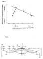
- FIG. 6 is a graph showing a relationship between change in an inclination angle ⁇ of a slope portion 14 and fuel consumption during load operation.
- the fuel consumption is maintained at a preferable value- Especially in a range in which the inclination angle ⁇ is 3 to 10°, the fuel consumption is in the best state.
- the inclination angle ⁇ exceeds 15°, the fuel consumption worsens sharply.
- FIG. 7 schematically shows a relationship between the black smoke during the no-load operation and the fuel consumption or cost during the load operation, where the prior-art in FIG. 8 is marked with ⁇ (diamond symbol) and the present embodiment is marked with • (circle cymbol). If NOx levels are the same, enhancement of the fuel consumption in the prior art results in increase in the black smoke (black smoke concentration) during the no-load operation while the fuel consumption can be enhanced while maintaining the black smoke concentration during the no-load operation at a substantially constant small value in the embodiment.
- the fuel spray does not collide with the slope of the mounting portion 12 of the combustion chamber 5 and the fuel hardly adheres to the slope of the mounting portion 12.
- the black smoke generation amount during the no-load operation can be suppressed and therefore it is possible to increase a nozzle hole 20 of the fuel injection valve 10 in size and to reduce the fuel consumption.
- the ratio L/d of the spray travel L to the nozzle hole diameter d is 150 ⁇ L/d ⁇ 250 so that the fuel spray reaches an area from the slope portion 14 to the saucer portion 15, it is possible to enhance an air utilization factor in a top clearance portion T while suppressing combustion on an inner face of the combustion chamber 5 and to reduce the fuel consumption while suppressing NOx.
- the inclination angle ⁇ of the slope portion 14 is 0° ⁇ 15° it is possible to smoothly disperse the fuel that has collided with the slope portion 14 from the saucer portion 15 to the top clearance portion T (FIG. 1) to thereby suppress NOx, suppress the black smoke, and reduce the fuel consumption.
Abstract
Description
- The present invention relates to a combustion chamber shape of a direct injection type diesel engine.
- FIG. 8 shows an example (Patent Document 1) of a prior-art combustion chamber shape in a direct injection type diesel engine. A combustion chamber (cavity) 106 in a shallow dish recessed shape is formed in a
top wall 102 of apiston 101. On a wall face of thecombustion chamber 106, amountain portion 104 spreading from a center of thecombustion chamber 106 and sloping gently to a vicinity of an outer peripheral end portion of the combustion chamber is formed and asaucer portion 105 seamlessly connected to a skirt end of themountain portion 104 and rising in an arc shape is formed. Afuel injection valve 103 is mounted to a cylinder head 110 so that a center O1 of a nozzle hole is positioned on a cylinder center line C1 and injects fuel in a conical shape toward thesaucer portion 105 of thecombustion chamber 106 at a predetermined nozzle hole angle α. - In a structure in FIG. 8, about a half of fuel spray directly collides with a slope of the
mountain portion 104 to thereby suppress fuel and a NOx generation amount. However, during no-load operation, a proportion of the fuel adhering to the slope of themountain portion 104 increases due to reduction in injection pressure to thereby increase black smoke. - Patent Document 1:
Japanese Patent Application Laid-open No. 5-106442 - In the structure as shown in FIG. 8, it is effective to reduce a nozzle hole area of the
fuel injection valve 103 to increase the injection pressure as a measure to suppress generation of the black smoke during the no-load operation. In this way, it is possible to facilitate atomization of the fuel during the no-load operation to suppress generation of the black smoke. - However, if the nozzle hole area of the fuel injection valve is reduced, a fuel injection time during a load operation becomes long to thereby worsen fuel consumption.
- Another effective measure to suppress generation of the black smoke is to increase the nozzle hole angle a in FIG. 8 to increase a spray travel to thereby direct the major portion of the fuel spray to the vicinity of the outer peripheral edge portion of the
combustion chamber 106. In this way, generation of the black smoke can be suppressed, but the NOx generation amount during load operation increases because combustion control on the wall face of the combustion chamber is not carried out. Moreover, flame becomes likely to collide with acylinder liner 112 to heat thecylinder liner 112 to thereby cause problems in reliability and durability of thecylinder liner 112. - It is an object of the present invention to provide a combustion chamber shape of a diesel engine in which a black smoke generation amount can be suppressed during no-load operation while suppressing NOx and maintaining fuel consumption at satisfactory values during load operation.
- In order to achieve the above object, according to an invention of
claim 1 of the present application, there is provided a combustion chamber shape of a direct injection type diesel engine having a combustion chamber formed in a recessed shape in a piston top wall and injecting fuel at a predetermined nozzle hole angle into the combustion chamber from a nozzle hole having a nozzle hole center substantially on a cylinder center line, wherein a wall face of the combustion chamber includes a mountain portion formed at a central portion in the combustion chamber and having such a slope angle and skirt end diameter that fuel spray does not collide with the mountain portion; a slope portion that inclines downward and outward from a skirt end of the mountain portion at a smaller angle than the slope angle of the mountain portion and with which the fuel spray collides; and a saucer portion which rises in an arc shape from an outer peripheral end of the slope portion to reach an outer peripheral end of the combustion chamber and with which the fuel spray collides. - According to an invention of
claim 2, there is provided a combustion chamber shape of a direct injection type diesel engine according toclaim 1,
wherein, in the mountain portion, a ratio H2/H1 of a mountain portion height H2 from a combustion chamber bottom face to a combustion chamber depth H1 is 0.7≤H2/H1≤1.0, a ratio D1/B of a diameter D1 of a mountain portion top face to a bore diameter B is D1/B≤0.3, and a ratio D2/B of a diameter D2 of the skirt end of the mountain portion to the bore diameter B is D2/B≤0.5. - According to an invention of
claim 3, there is provided a combustion chamber shape of a direct injection type diesel engine according toclaim - According to an invention of claim 4, there is provided a combustion chamber shape of a direct injection type diesel engine according to any one of
claims 1 to 3, wherein the slope angle θ of the slope portion is 0°<θ≤15°. -
- (1) The combustion chamber wall face is formed with the slope portion inclining downwardly to outside between the central mountain portion and the arc-shaped saucer portion at the outer peripheral end portion so that the fuel spray does not collide with the slope of the mountain portion but comes in contact with the area from the slope portion to the saucer portion. Therefore, during the no-load operation, the fuel spray becomes less likely to adhere to the slope of the mountain portion to thereby suppress generation of the black smoke. Moreover, by causing the fuel spray to collide with the area from the slope face to the saucer portion to disperse the fuel spray, it is possible to suppress a NOx generation amount during load operation. Furthermore, because it is unnecessary to reduce a nozzle hole area in order to increase injection pressure, it is possible to reduce fuel consumption during the load operation.
- (2) Because the ratio of the mountain portion height H2 to the combustion chamber depth H1 is 0.7≤H2/H1≤1.0, the ratio of the diameter D1 of the mountain portion top face to the bore diameter B is D1/B≤0.3, and the ratio of the diameter D2 of the skirt end of the mountain portion to the bore diameter B is D2/B≤0.5 while maintaining a compression ratio constant, it is possible to enhance the black smoke suppressing effect during the no-load operation.
- (3) Because the ratio of the spray travel L to the nozzle hole diameter d is 150≤L/d≤250, it is possible to effectively use air in a top clearance portion T while suppressing combustion at the slope portion and the saucer portion. Therefore, it is possible to reduce the fuel consumption while suppressing NOx during the load operation.
- (4) Because the slope angle θ of the slope portion is 0°<θ≤15°, it is possible to smoothly lead the fuel spray from the slope portion to the saucer portion and the top clearance portion to thereby reduce the fuel consumption while suppressing NOx during the load operation.
-
- FIG. 1 is a vertical sectional enlarged view of a combustion chamber of a direct injection type diesel engine to which the present invention is applied.
- FIG. 2 is a vertical sectional enlarged view of a nozzle hole portion of a fuel injection valve in FIG. 1.
- FIG. 3 is a drawing showing a relationship between change in a ratio H2/H1 of a mountain portion height H2 from a bottom face of the combustion chamber to a combustion chamber depth H1 and black smoke (black smoke concentration) during no-load operation.
- FIG. 4 is a drawing showing a relationship between change in a ratio D1/B of a diameter D1 of a top face of the mountain portion to a bore diameter B and the black smoke (black smoke concentration) during the no-load operation.
- FIG. 5 is a drawing showing a relationship between change in a ratio D2/B of a diameter D2 of a skirt end of the mountain portion to the bore diameter B and the black smoke (black smoke concentration) during the no-load operation.
- FIG. 6 is a graph showing a relationship between change in an inclination angle θ of a slope portion and fuel consumption during load operation.
- FIG. 7 is a drawing showing a relationship between the black smoke during the no-load operation and the fuel consumption during the load operation.
- FIG. 8 is a vertical sectional enlarged view of a prior-art combustion chamber.
-
- 1 Cylinder liner
- 2 Piston
- 3 Piston top wall
- 5 Combustion chamber
- 7 Cylinder head
- 10 Fuel injection valve
- 12 Mountain portion
- 13 Top face of mountain portion
- 14 Slope portion
- 15 Saucer portion
- 20 Nozzle hole
- FIG. 1 is an enlarged vertical sectional view of a combustion chamber of a direct injection type diesel engine to which the present invention is applied. In FIG. 1, a
piston 2 is fitted in acylinder liner 1 of a cylinder block, a combustion chamber (cavity) 5 is formed on atop wall 3 of thepiston 2, and an upper portion of the combustion chamber 5 is closed with a lower face of acylinder head 7. Afuel injection valve 10 with its nozzle hole center O1 positioned on a cylinder center line C1 is mounted to thecylinder head 7 and injects (sprays) fuel in a conical shape at a nozzle hole angle a. In FIG. 1, thepiston 2 is positioned at a top dead center. - The combustion chamber 5 is formed in a shallow dish shape, where a
mounting portion 12 in a shape of a truncated cone is formed at a central portion (on the cylinder center line C1) and asaucer portion 15 gently rising outward in an arc shape is formed in an annular shape at an outer peripheral portion. Between thesaucer portion 15 and thecentral mounting portion 12, aslope portion 14 inclining downward and outward at a predetermined angle θ with respect to a plane Q orthogonal to the cylinder center line C1 is formed in an annular shape. An inner peripheral end of theslope portion 14 and a skirt end portion of themounting portion 12 are seamlessly connected to each other through a curved face at a boundary P1 and an outer peripheral end of theslope portion 14 and an inner peripheral end of thesaucer portion 15 are seamlessly connected to each other at a boundary P2. - The
mounting portion 12 is formed ,in condition that a compression ratio is constant, so that a ratio H2/H1 of a mountain portion height H2 from a bottom face of the combustion chamber to a combustion chamber depth H1 is in a range of 0.7≤H2/H1≤1.0, that a ratio D1/B of a diameter D1 of atop face 13 of the mountain portion to a bore diameter B is in a range of D1/B≤0.3, and that a ratio D2/B of a diameter D2 of the skirt end (P1) of themountain portion 12 to the bore diameter B is in a range of D2/B0.5. A slope of themounting portion 12 is at least at a certain distance from a minimum spray angle range s1 of the fuel spray so that the fuel spray does not collide with the slope of themounting portion 12. - The inclination angle θ of the
slope portion 14 is much smaller than an angle of the slope of thecentral mountain portion 10 and theslope portion 14 is formed in such an area that about an inner half of the whole spray angle can collide with theslope portion 14. - The
saucer portion 15 gently rises and is formed in such an area that a center line S0 of the fuel spray collides with a vicinity of the boundary P2 between theslope portion 14 and thesaucer portion 15. - Alength of the fuel spray center line S0 from the nozzle hole center O1 to the
saucer portion 15, i.e., a so-called spray travel L is set with respect to a nozzle hole diameter d shown in FIG. 2 so that L/d is in a range of 150 to 250 and is preferably about 160 to 210. - FIG. 3 is a drawing showing a relationship between change in a ratio H2/H1 of a mountain portion height H2 to a combustion chamber depth H1 and black smoke (black smoke concentration) during no-load operation when the compression ratio is maintained constant- As can be understood from FIG. 3, in a range in which the above ratio H2/H1 is 0.85 to 1.00, a black smoke generation amount is suppressed to a minimum value and does not change. In a range in which the above ratio H2/H1 decreases from 0.85 to 0.7, the black smoke generation amount increases mildly. If the above ratio H2/H1 becomes smaller than 0.7, the black smoke generation amount increases sharply. Therefore, by setting the above ratio H2/H1 in a range of 0.7≤H2/H1≤1.0, it is possible to suppress the black smoke generation amount in a permissible range. Preferably, by setting the ratio in a range of 0.85≤H2/H1≤1.0, it is possible to effectively suppress the black smoke generation amount.
- FIG. 4 is a drawing showing a relationship between change in a ratio D1/B of a diameter D1 of a
top face 13 of the mountain portion to a bore diameter B and the black smoke (black smoke concentration) during the no-load operation. As can be understood from FIG. 4, in a range in which the above ratio D1/B is 0.3 or smaller, the black smoke during the no-load operation is maintained in a satisfactory state. Especially in a range in which the above ratio D1/B is 0.15 or smaller, the black smoke is suppressed to a minimum value. On the other hand, if the above ratio D1/B becomes greater than 0.3, the black smoke increases sharply. Therefore, by setting the above ratio D1/B in a range of D1/B≤0.3, it is possible to suppress the black smoke generation amount in a permissible range. Preferably, by setting the ratio in a range of D1/B≤0.15, it is possible to effectively suppress the black smoke generation amount. - FIG. 5 is a drawing showing a relationship between change in a ratio D2/B of a diameter D2 of the skirt end P1 of the
mountain portion 12 to the bore diameter B and the black smoke (black smoke concentration) during the no-load operation. As can be understood from FIG. 5, in a range in which the above ratio D2/B is 0.5 or smaller, the black smoke during the no-load operation is maintained in a satisfactory state. Especially in a range in which the above ratio D2/B is 0.3 or smaller, the black smoke is suppressed to a minimum value. On the other hand, if the above ratio D1/B becomes greater than 0.5, the black smoke increases sharply. Therefore, by setting the above ratio D2/B in a range of D2/B≤0.5, it is possible to suppress the black smoke generation amount in a permissible range. Preferably, by setting the ratio in a range of D2/B≤0.3, it is possible to effectively suppress the black smoke generation amount. - FIG. 6 is a graph showing a relationship between change in an inclination angle θ of a
slope portion 14 and fuel consumption during load operation. As can be understood from FIG. 6, in a range in which the above inclination angle θ is greater than 0° and equal to or smaller than 15°, the fuel consumption is maintained at a preferable value- Especially in a range in which the inclination angle θ is 3 to 10°, the fuel consumption is in the best state. On the other hand, if the inclination angle θ exceeds 15°, the fuel consumption worsens sharply. - FIG. 7 schematically shows a relationship between the black smoke during the no-load operation and the fuel consumption or cost during the load operation, where the prior-art in FIG. 8 is marked with ◆ (diamond symbol) and the present embodiment is marked with • (circle cymbol). If NOx levels are the same, enhancement of the fuel consumption in the prior art results in increase in the black smoke (black smoke concentration) during the no-load operation while the fuel consumption can be enhanced while maintaining the black smoke concentration during the no-load operation at a substantially constant small value in the embodiment.
- In other words, in the embodiment, because 0.7≤H2/H1≤1.0, D1/B≤0.3, and D2/B≤0.5, the fuel spray does not collide with the slope of the mounting
portion 12 of the combustion chamber 5 and the fuel hardly adheres to the slope of the mountingportion 12. As a result, the black smoke generation amount during the no-load operation can be suppressed and therefore it is possible to increase anozzle hole 20 of thefuel injection valve 10 in size and to reduce the fuel consumption. Moreover, because the ratio L/d of the spray travel L to the nozzle hole diameter d is 150≤L/d≤250 so that the fuel spray reaches an area from theslope portion 14 to thesaucer portion 15, it is possible to enhance an air utilization factor in a top clearance portion T while suppressing combustion on an inner face of the combustion chamber 5 and to reduce the fuel consumption while suppressing NOx. Furthermore, because the inclination angle θ of theslope portion 14 is 0°<θ≤15° it is possible to smoothly disperse the fuel that has collided with theslope portion 14 from thesaucer portion 15 to the top clearance portion T (FIG. 1) to thereby suppress NOx, suppress the black smoke, and reduce the fuel consumption.
Claims (4)
- A combustion chamber shape of a direct injection type diesel engine having a combustion chamber formed in a recessed shape in a piston top wall and injecting fuel at a predetermined nozzle hole angle into the combustion chamber from a nozzle hole of a fuel injection valve having a nozzle hole center substantially on a cylinder center line,
wherein a wall face of the combustion chamber includes:a conical mountain portion formed at a central portion in the combustion chamber and having such a slope angle and skirt end diameter that fuel spray does not collide with the mountain portion;a slope portion that inclines downward and outward from a skirt end of the mountain portion at a smaller angle than the slope angle of the mountain portion and with which the fuel spray collides; anda saucer portion which rises in an arc shape from an outer peripheral end of the slope portion to reach an outer peripheral end of the combustion chamber and with which the fuel spray collides. - A combustion chamber shape of a direct injection type diesel engine according to claim 1,
wherein, in the mountain portion, a ratio H2/H1 of a mountain portion height H2 from a combustion chamber bottom face to a combustion chamber depth H1 is 0.7≤H2/H1≤1.0,
a ratio D1/B of a diameter D1 of a mountain portion top face to a bore diameter B is D1/B≤0.3, and
a ratio D2/B of a diameter D2 of the skirt end of the mountain portion to the bore diameter B is D2/B≤0.5. - A combustion chamber shape of a direct injection type diesel engine according to claim 1 or 2, wherein a ratio L/d of a spray travel L to a nozzle hole diameter d is 150≤L/d≤250.
- A combustion chamber shape of a direct injection type diesel engine according to any one of claims 1 to 3, wherein the slope angle θ of the slope portion is 0°<θ≤15°.
Applications Claiming Priority (2)
| Application Number | Priority Date | Filing Date | Title |
|---|---|---|---|
| JP2004203257A JP4384945B2 (en) | 2004-07-09 | 2004-07-09 | Combustion chamber shape of direct injection diesel engine |
| PCT/JP2005/009545 WO2006006308A1 (en) | 2004-07-09 | 2005-05-25 | Shape of combustion chamber of direct-injection diesel engine |
Publications (3)
| Publication Number | Publication Date |
|---|---|
| EP1767758A1 true EP1767758A1 (en) | 2007-03-28 |
| EP1767758A4 EP1767758A4 (en) | 2010-08-11 |
| EP1767758B1 EP1767758B1 (en) | 2012-02-22 |
Family
ID=35783665
Family Applications (1)
| Application Number | Title | Priority Date | Filing Date |
|---|---|---|---|
| EP05743770A Expired - Fee Related EP1767758B1 (en) | 2004-07-09 | 2005-05-25 | Shape of combustion chamber of direct-injection diesel engine |
Country Status (6)
| Country | Link |
|---|---|
| US (1) | US7472678B2 (en) |
| EP (1) | EP1767758B1 (en) |
| JP (1) | JP4384945B2 (en) |
| CN (1) | CN100504048C (en) |
| DK (1) | DK1767758T3 (en) |
| WO (1) | WO2006006308A1 (en) |
Cited By (1)
| Publication number | Priority date | Publication date | Assignee | Title |
|---|---|---|---|---|
| EP2987981A1 (en) * | 2014-08-19 | 2016-02-24 | Deere & Company | Engine for use in a machine |
Families Citing this family (16)
| Publication number | Priority date | Publication date | Assignee | Title |
|---|---|---|---|---|
| DE102004045634A1 (en) * | 2004-09-21 | 2006-04-06 | Daimlerchrysler Ag | Internal combustion engine |
| FR2925601A1 (en) * | 2007-12-19 | 2009-06-26 | Renault Sas | COMBUSTION CHAMBER FOR THERMAL ENGINE |
| FI121089B (en) * | 2008-05-19 | 2010-06-30 | Waertsilae Finland Oy | Compression ignition internal combustion engine and method for operating an internal combustion engine |
| US10180115B2 (en) | 2010-04-27 | 2019-01-15 | Achates Power, Inc. | Piston crown bowls defining combustion chamber constructions in opposed-piston engines |
| WO2012158756A1 (en) | 2011-05-18 | 2012-11-22 | Achates Power, Inc. | Combustion chamber construction for opposed-piston engines |
| US9512779B2 (en) | 2010-04-27 | 2016-12-06 | Achates Power, Inc. | Swirl-conserving combustion chamber construction for opposed-piston engines |
| US8800528B2 (en) | 2010-04-27 | 2014-08-12 | Achates Power, Inc. | Combustion chamber constructions for opposed-piston engines |
| EP2606202B1 (en) | 2010-08-16 | 2016-03-09 | Achates Power, Inc. | Fuel injection spray patterns for opposed-piston engines |
| US20130104848A1 (en) | 2011-10-27 | 2013-05-02 | Achates Power, Inc. | Fuel Injection Strategies in Opposed-Piston Engines with Multiple Fuel Injectors |
| DE102012103195A1 (en) | 2012-04-13 | 2013-10-17 | Mwm Gmbh | Piston of an internal combustion engine |
| DE102012103212A1 (en) * | 2012-04-13 | 2013-10-17 | Mwm Gmbh | Piston of an internal combustion engine |
| DE102012103206B4 (en) | 2012-04-13 | 2017-08-03 | Caterpillar Energy Solutions Gmbh | Piston of an internal combustion engine |
| US9211797B2 (en) | 2013-11-07 | 2015-12-15 | Achates Power, Inc. | Combustion chamber construction with dual mixing regions for opposed-piston engines |
| CN103835803B (en) * | 2014-02-24 | 2016-02-24 | 大连理工大学 | Diesel engine collision shunting combustion room |
| JP6160564B2 (en) * | 2014-06-09 | 2017-07-12 | マツダ株式会社 | diesel engine |
| CN104632353B (en) * | 2014-12-26 | 2018-06-05 | 江苏大学 | A kind of diesel engine with direct injection collision atomization diffusion combustion system |
Citations (8)
| Publication number | Priority date | Publication date | Assignee | Title |
|---|---|---|---|---|
| FR840691A (en) * | 1938-07-15 | 1939-05-02 | Internal combustion engine | |
| GB751585A (en) * | 1953-10-08 | 1956-06-27 | Schweizerische Lokomotiv | Improvements in or relating to internal combustion engines of the fuel injection type |
| GB967126A (en) * | 1962-12-06 | 1964-08-19 | John Peter Hindley | Improvements in internal combustion engines |
| JPH05106442A (en) * | 1991-10-15 | 1993-04-27 | Yanmar Diesel Engine Co Ltd | Direct injection type diesel engine |
| JPH06185364A (en) * | 1992-12-16 | 1994-07-05 | Isuzu Motors Ltd | Combustion chamber of direct-injection type diesel engine |
| US5868112A (en) * | 1996-12-19 | 1999-02-09 | Cummins Engine Company, Inc. | Deep angle injection nozzle and piston having complementary combustion bowl |
| DE10135062A1 (en) * | 2001-07-18 | 2003-02-13 | Invent Gmbh Entwicklung Neuer Technologien | Method of burning fuel and combustion chamber |
| JP2003214297A (en) * | 2002-01-24 | 2003-07-30 | Yanmar Co Ltd | Fuel injection valve of diesel engine |
Family Cites Families (15)
| Publication number | Priority date | Publication date | Assignee | Title |
|---|---|---|---|---|
| US2828724A (en) * | 1953-10-08 | 1958-04-01 | Schweizerische Lokomotiv | Internal combustion engines of the injection type |
| US2914044A (en) * | 1955-09-07 | 1959-11-24 | Maschf Augsburg Nuernberg Ag | Self-igniting combustion engine |
| DE2945490A1 (en) * | 1978-11-16 | 1980-05-22 | List Hans | AIR COMPRESSING, DIRECTLY INJECTING INTERNAL COMBUSTION ENGINE |
| JPS55153816A (en) * | 1979-05-17 | 1980-12-01 | Yanmar Diesel Engine Co Ltd | Combustion chamber of direct injection type diesel engine |
| US4364342A (en) * | 1980-10-01 | 1982-12-21 | Ford Motor Company | Ignition system employing plasma spray |
| CN1015395B (en) * | 1988-02-08 | 1992-02-05 | 胡国栋 | Guide ring mounted in the combustion room of a direct-spraying type diesel engine |
| US5099809A (en) * | 1989-08-09 | 1992-03-31 | Mitsubishi Jidosha Kogyo Kabushiki Kaisha | Combustion chamber for a diesel engine |
| JPH07189701A (en) * | 1993-12-27 | 1995-07-28 | Hino Motors Ltd | Piston for internal combustion engine |
| JPH0828276A (en) * | 1994-07-14 | 1996-01-30 | Mitsubishi Heavy Ind Ltd | Combustion chamber for internal combustion engine |
| JP2001115844A (en) * | 1999-10-19 | 2001-04-24 | Yanmar Diesel Engine Co Ltd | Combustion chamber for direct injection diesel engine |
| WO2001055567A1 (en) * | 2000-01-25 | 2001-08-02 | Kabushiki Kaisha Toyota Chuo Kenkyusho | Direct injection type internal combustion engine |
| JP2002349267A (en) | 2001-05-28 | 2002-12-04 | Isuzu Motors Ltd | Combustion system of diesel engine |
| FR2839114B1 (en) * | 2002-04-24 | 2004-07-30 | Renault Sa | COMBUSTION CHAMBER OF MULTI-CYLINDER COMPRESSION IGNITION ENGINE, IN PARTICULAR OF DIRECT INJECTION DIESEL TYPE, AND ASSOCIATED ENGINE |
| US6739308B1 (en) * | 2002-05-24 | 2004-05-25 | Hatch & Kirk, Inc. | Fuel igniter and head for use in diesel engines and related systems and methods |
| US7032566B2 (en) * | 2003-05-30 | 2006-04-25 | Caterpillar Inc. | Fuel injector nozzle for an internal combustion engine |
-
2004
- 2004-07-09 JP JP2004203257A patent/JP4384945B2/en active Active
-
2005
- 2005-05-25 WO PCT/JP2005/009545 patent/WO2006006308A1/en not_active Application Discontinuation
- 2005-05-25 EP EP05743770A patent/EP1767758B1/en not_active Expired - Fee Related
- 2005-05-25 CN CNB2005800229325A patent/CN100504048C/en not_active Expired - Fee Related
- 2005-05-25 US US11/629,707 patent/US7472678B2/en active Active
- 2005-05-25 DK DK05743770.9T patent/DK1767758T3/en active
Patent Citations (8)
| Publication number | Priority date | Publication date | Assignee | Title |
|---|---|---|---|---|
| FR840691A (en) * | 1938-07-15 | 1939-05-02 | Internal combustion engine | |
| GB751585A (en) * | 1953-10-08 | 1956-06-27 | Schweizerische Lokomotiv | Improvements in or relating to internal combustion engines of the fuel injection type |
| GB967126A (en) * | 1962-12-06 | 1964-08-19 | John Peter Hindley | Improvements in internal combustion engines |
| JPH05106442A (en) * | 1991-10-15 | 1993-04-27 | Yanmar Diesel Engine Co Ltd | Direct injection type diesel engine |
| JPH06185364A (en) * | 1992-12-16 | 1994-07-05 | Isuzu Motors Ltd | Combustion chamber of direct-injection type diesel engine |
| US5868112A (en) * | 1996-12-19 | 1999-02-09 | Cummins Engine Company, Inc. | Deep angle injection nozzle and piston having complementary combustion bowl |
| DE10135062A1 (en) * | 2001-07-18 | 2003-02-13 | Invent Gmbh Entwicklung Neuer Technologien | Method of burning fuel and combustion chamber |
| JP2003214297A (en) * | 2002-01-24 | 2003-07-30 | Yanmar Co Ltd | Fuel injection valve of diesel engine |
Non-Patent Citations (1)
| Title |
|---|
| See also references of WO2006006308A1 * |
Cited By (1)
| Publication number | Priority date | Publication date | Assignee | Title |
|---|---|---|---|---|
| EP2987981A1 (en) * | 2014-08-19 | 2016-02-24 | Deere & Company | Engine for use in a machine |
Also Published As
| Publication number | Publication date |
|---|---|
| US20070272191A1 (en) | 2007-11-29 |
| US7472678B2 (en) | 2009-01-06 |
| WO2006006308A1 (en) | 2006-01-19 |
| JP2006022773A (en) | 2006-01-26 |
| CN100504048C (en) | 2009-06-24 |
| DK1767758T3 (en) | 2012-03-26 |
| CN1981118A (en) | 2007-06-13 |
| EP1767758A4 (en) | 2010-08-11 |
| EP1767758B1 (en) | 2012-02-22 |
| JP4384945B2 (en) | 2009-12-16 |
Similar Documents
| Publication | Publication Date | Title |
|---|---|---|
| EP1767758A1 (en) | Shape of combustion chamber of direct-injection diesel engine | |
| US6705275B2 (en) | Incylinder direct injection spark ignition engine | |
| JP6215943B2 (en) | Diesel engine combustion chamber structure | |
| US3836080A (en) | Fuel injection nozzle | |
| EP1801381B1 (en) | Shape of combustion chamber of direct injection diesel engine | |
| EP0172253B1 (en) | Combustion chamber structure for diesel engines | |
| EP2034156B1 (en) | Direct fuel injection diesel engine | |
| EP1469193B1 (en) | Fuel injection valve for diesel engine | |
| EP2039905A1 (en) | Fuel direct-injection diesel engine | |
| JP2010025123A (en) | Fuel direct-injection diesel engine | |
| JP2010101243A (en) | Piston for diesel internal combustion engine | |
| CN102959222A (en) | Piston for spark-ignition engine | |
| WO2015177897A1 (en) | Combustion chamber structure for diesel engine | |
| US4506833A (en) | Fuel injection nozzle for an internal combustion engine | |
| EP2840243A1 (en) | Combustion chamber structure for direct injection engine | |
| JP2017025929A (en) | Combustion chamber structure of diesel engine | |
| US11319867B2 (en) | Piston bowl for an internal combustion engine | |
| US6513476B1 (en) | Piston having combustion chamber defined in the crown | |
| KR100819260B1 (en) | Shape of combustion chamber of direct-injection diesel engine | |
| US10662866B2 (en) | Diesel engine and method for fuel distribution and combustion in combustion chamber of diesel engine | |
| GB2057057A (en) | Fuel injector for diesel engine | |
| JPH0921321A (en) | Fuel injection method for direct injection type diesel engine, piston and injection nozzle employed by the method | |
| JPH0569335U (en) | Combustion chamber of direct injection diesel engine | |
| JP3707247B2 (en) | Sub-chamber engine with a sub-chamber in the piston | |
| US20200063644A1 (en) | Diesel engine |
Legal Events
| Date | Code | Title | Description |
|---|---|---|---|
| PUAI | Public reference made under article 153(3) epc to a published international application that has entered the european phase |
Free format text: ORIGINAL CODE: 0009012 |
|
| 17P | Request for examination filed |
Effective date: 20070108 |
|
| AK | Designated contracting states |
Kind code of ref document: A1 Designated state(s): DE DK FI GB |
|
| DAX | Request for extension of the european patent (deleted) | ||
| RBV | Designated contracting states (corrected) |
Designated state(s): DE DK FI GB |
|
| RBV | Designated contracting states (corrected) |
Designated state(s): DE DK FI GB |
|
| A4 | Supplementary search report drawn up and despatched |
Effective date: 20100709 |
|
| 17Q | First examination report despatched |
Effective date: 20101109 |
|
| GRAP | Despatch of communication of intention to grant a patent |
Free format text: ORIGINAL CODE: EPIDOSNIGR1 |
|
| GRAS | Grant fee paid |
Free format text: ORIGINAL CODE: EPIDOSNIGR3 |
|
| GRAA | (expected) grant |
Free format text: ORIGINAL CODE: 0009210 |
|
| AK | Designated contracting states |
Kind code of ref document: B1 Designated state(s): DE DK FI GB |
|
| REG | Reference to a national code |
Ref country code: GB Ref legal event code: FG4D |
|
| REG | Reference to a national code |
Ref country code: DK Ref legal event code: T3 |
|
| REG | Reference to a national code |
Ref country code: DE Ref legal event code: R096 Ref document number: 602005032797 Country of ref document: DE Effective date: 20120419 |
|
| PLBE | No opposition filed within time limit |
Free format text: ORIGINAL CODE: 0009261 |
|
| STAA | Information on the status of an ep patent application or granted ep patent |
Free format text: STATUS: NO OPPOSITION FILED WITHIN TIME LIMIT |
|
| 26N | No opposition filed |
Effective date: 20121123 |
|
| REG | Reference to a national code |
Ref country code: DE Ref legal event code: R097 Ref document number: 602005032797 Country of ref document: DE Effective date: 20121123 |
|
| REG | Reference to a national code |
Ref country code: DE Ref legal event code: R082 Ref document number: 602005032797 Country of ref document: DE Representative=s name: DOMPATENT VON KREISLER SELTING WERNER - PARTNE, DE Ref country code: DE Ref legal event code: R081 Ref document number: 602005032797 Country of ref document: DE Owner name: YANMAR POWER TECHNOLOGY CO., LTD., JP Free format text: FORMER OWNER: YANMAR CO., LTD., OSAKA-SHI, JP |
|
| REG | Reference to a national code |
Ref country code: FI Ref legal event code: PCE Owner name: YANMAR POWER TECHNOLOGY CO., LTD. |
|
| PGFP | Annual fee paid to national office [announced via postgrant information from national office to epo] |
Ref country code: DE Payment date: 20210520 Year of fee payment: 17 Ref country code: FI Payment date: 20210520 Year of fee payment: 17 |
|
| PGFP | Annual fee paid to national office [announced via postgrant information from national office to epo] |
Ref country code: DK Payment date: 20210521 Year of fee payment: 17 Ref country code: GB Payment date: 20210520 Year of fee payment: 17 |
|
| REG | Reference to a national code |
Ref country code: DE Ref legal event code: R119 Ref document number: 602005032797 Country of ref document: DE |
|
| REG | Reference to a national code |
Ref country code: DK Ref legal event code: EBP Effective date: 20220531 |
|
| GBPC | Gb: european patent ceased through non-payment of renewal fee |
Effective date: 20220525 |
|
| PG25 | Lapsed in a contracting state [announced via postgrant information from national office to epo] |
Ref country code: FI Free format text: LAPSE BECAUSE OF NON-PAYMENT OF DUE FEES Effective date: 20220525 |
|
| PG25 | Lapsed in a contracting state [announced via postgrant information from national office to epo] |
Ref country code: DK Free format text: LAPSE BECAUSE OF NON-PAYMENT OF DUE FEES Effective date: 20220531 |
|
| PG25 | Lapsed in a contracting state [announced via postgrant information from national office to epo] |
Ref country code: GB Free format text: LAPSE BECAUSE OF NON-PAYMENT OF DUE FEES Effective date: 20220525 Ref country code: DE Free format text: LAPSE BECAUSE OF NON-PAYMENT OF DUE FEES Effective date: 20221201 |