EP1767418A2 - Vehicle wash system - Google Patents
Vehicle wash system Download PDFInfo
- Publication number
- EP1767418A2 EP1767418A2 EP06019400A EP06019400A EP1767418A2 EP 1767418 A2 EP1767418 A2 EP 1767418A2 EP 06019400 A EP06019400 A EP 06019400A EP 06019400 A EP06019400 A EP 06019400A EP 1767418 A2 EP1767418 A2 EP 1767418A2
- Authority
- EP
- European Patent Office
- Prior art keywords
- vehicle
- track
- fact
- along
- vehicles
- Prior art date
- Legal status (The legal status is an assumption and is not a legal conclusion. Google has not performed a legal analysis and makes no representation as to the accuracy of the status listed.)
- Withdrawn
Links
Images




Classifications
-
- B—PERFORMING OPERATIONS; TRANSPORTING
- B60—VEHICLES IN GENERAL
- B60S—SERVICING, CLEANING, REPAIRING, SUPPORTING, LIFTING, OR MANOEUVRING OF VEHICLES, NOT OTHERWISE PROVIDED FOR
- B60S3/00—Vehicle cleaning apparatus not integral with vehicles
- B60S3/04—Vehicle cleaning apparatus not integral with vehicles for exteriors of land vehicles
-
- B—PERFORMING OPERATIONS; TRANSPORTING
- B60—VEHICLES IN GENERAL
- B60S—SERVICING, CLEANING, REPAIRING, SUPPORTING, LIFTING, OR MANOEUVRING OF VEHICLES, NOT OTHERWISE PROVIDED FOR
- B60S3/00—Vehicle cleaning apparatus not integral with vehicles
- B60S3/04—Vehicle cleaning apparatus not integral with vehicles for exteriors of land vehicles
- B60S3/06—Vehicle cleaning apparatus not integral with vehicles for exteriors of land vehicles with rotary bodies contacting the vehicle
Definitions
- tunnels are extremely complicated to install and require considerable maintenance. In addition, they entail a large consumption of water and electricity. Their advantages lie in the fact that they are highly automated and are capable of washing a higher number of vehicles per hour, since several vehicles can be washed simultaneously, distributed at each station along the tunnel, but the washing of one vehicle requires a considerable length of time.
- the system could have a system for spraying de-mineralised water at the bridge exit, as the final washing mechanism, to enable the vehicle to dry more quickly as it is driven along the road.
- De-mineralised water does not leave stains or marks on the vehicle body when it dries, giving it a perfect shine.
- the system is more economical than drying with air, thereby ensuring an important reduction in electricity consumption and cuts system assembly and maintenance costs.
- the washing system could have an end station for rinsing, waxing and rinsing with de-mineralised water at the track exit.
- This station has a grille of pipes connected to each other with a great many holes or openings for spraying liquids over the whole of the vehicle parked at that station.
- the system is formed by a fixed bridge (1) placed over a track (2) along which the vehicle to be washed is driven.
- This track is not fitted with any (2) mechanisms that pull the vehicle along and the vehicle is powered by its own engine.
- luminous signals (3) are connected to a control device (4), for example a PLC, which can activate successive programmed signals, so that the vehicle takes a certain length of time to travel along the track (2) or, as shown in the example contained in the figures, activate the luminous signals in a controller manner, depending on the information furnished by a set of sensors (5) which detect the vehicle's position on the track (2).
- a control device (4) for example a PLC, which can activate successive programmed signals, so that the vehicle takes a certain length of time to travel along the track (2) or, as shown in the example contained in the figures, activate the luminous signals in a controller manner, depending on the information furnished by a set of sensors (5) which detect the vehicle's position on the track (2).
- the system could have a single station at the exit (7) for rinsing, waxing and rinsing again with de-mineralised water.
- This end station (7) has a grille (71) of tubular elements connected to each other, fitted with many holes or openings (72) for spraying liquids onto the whole of the vehicle parked at that station.
- a set of conduits (73, 74, 75) are connected to the grille (71) for alternately spraying rinsing water, water containing wax additives and de-mineralised water in sequence and these liquids are sprayed in succession onto the vehicle in the end station described above (7).
Landscapes
- Engineering & Computer Science (AREA)
- Mechanical Engineering (AREA)
- Vehicle Cleaning, Maintenance, Repair, Refitting, And Outriggers (AREA)
Abstract
Description
- The present invention refers to a vehicle wash system, of the type that comprises a fixed bridge containing the appropriate mechanisms for washing vehicles, which may or may not come into contact with the vehicle, and a lane or track underneath the bridge, along which the vehicles pass through to be washed.
- There are currently many different systems and devices available for washing vehicles, removing the dirt from vehicle bodies and improving their general appearance. Many of these systems are on offer to the public at large, for use after first paying for the services provided. These systems operate under totally automatic conditions or may be operated by hand.
- One example are what are known as wash "boxes" in which there is a pistol that sprays soapy water and pressurised water so that users can wash their vehicles. In this example, the users wash their vehicles themselves, with the need to spend considerable time performing the operation, with the ensuing risk of getting wet or stained.
- Another system is the vehicle wash system in which users leave their vehicles in a specific area, where a moving bridge moves lengthwise. This moving bridge has a series of mechanisms for washing the vehicle, that may or may not come into contact with the vehicle. In the first case the moving bridge has mechanisms for spraying water and soap, and rollers or fabric strips that rub the body of the vehicle, while in the second case, the moving bridge has no rollers or fabric strips and applies onto the vehicle soap, liquid additives, pressurised water or other appropriate fluids to clean the bodywork, but without rubbing it with textile elements.
- The moving bridge performs one or two functions during each run. However, these systems are fragile and costly, as the washing and supply fixtures are hung from a moving bridge. During each wash, the bridge has to move several times along rails, and travelling along the whole length of each vehicle in every run. Even though the cleaning time is shortened using these washing bridges, they still need a certain length of time to travel up and down the whole vehicle several times.
- There are also vehicle wash tunnels, formed by a bridge that is fixed to a lane or track where the vehicles enter the tunnel at one end and emerge from the other end after being washed. This bridge contains all the necessary means for washing the vehicle, with and without touching the vehicle, as well as the elements necessary to spray water onto the body, such as jets, mechanisms for applying soap or detergent and as an option, a set of rollers or fabric strips that rub the vehicle body. At the end where the vehicles leave the vehicle wash tunnels, there are systems for rinsing off the soap and drying the vehicles by means of blowing air onto the vehicle. The vehicle moves forwards inside the tunnel by means of a chain that pulls it along in which one of the vehicle's wheels is inserted, moving it forwards. These tunnels are extremely complicated to install and require considerable maintenance. In addition, they entail a large consumption of water and electricity. Their advantages lie in the fact that they are highly automated and are capable of washing a higher number of vehicles per hour, since several vehicles can be washed simultaneously, distributed at each station along the tunnel, but the washing of one vehicle requires a considerable length of time.
- The vehicle wash system presented in this invention has a series of technical peculiarities that are aimed at achieving; greater: simplicity in terms of construction, with less manufacturing costs. For this reason it has no mechanisms for pulling the vehicle along and no drying mechanisms; washing the vehicle takes up far less time and is more economical since users drive their own vehicles slowly through the fixed bridge facility, powered by the vehicle engine, which makes it possible to cut down on operating expenses by reducing the system operating power, precisely due to eliminating the mechanisms for drying the vehicle and moving it along.
- This system, which is formed by a fixed bridge laid out over a lane or track along which the vehicle to be washed is driven, includes a set of luminous signals distributed along the bridge or track, connected to a control device or PLC. The luminous signals tell the vehicle driver when to stop and when to move forwards along the wash track, so that the vehicle always moves along at the right speed to ensure it is washed properly.
- The vehicle moves along the wash track powered by its own engine, and unlike what occurs with traditional washing tunnels, the track has no mechanisms in place for pulling the vehicle along.
- The device responsible for the control of the luminous signals is preferably a PLC (programmable logical controller), that activates the programmed successive luminous signals in such a way that the vehicle takes a certain time to move along the wash track, and the luminous signals authorise the next vehicle in line to pass through the wash track, once the previous vehicle approaches the exit.
- As an option, the system could have a series of sensors at intervals along the track, for detecting the position of the vehicle. These sensors are connected to the control that operates the luminous signals. In this case activating the luminous signals by the control device is done, depending on the position of the vehicle or vehicles moving along the track.
- These luminous signals may be traffic lights laid out along the track, so that the driver moves along intuitively, depending on the signals already received, since the sequence of these signals is similar to the one used on roads: for example, red to indicate the need to stop or slow down, and green to let the driver know he can move forwards along the track.
- The system could have a system for spraying de-mineralised water at the bridge exit, as the final washing mechanism, to enable the vehicle to dry more quickly as it is driven along the road. De-mineralised water does not leave stains or marks on the vehicle body when it dries, giving it a perfect shine. In addition, the system is more economical than drying with air, thereby ensuring an important reduction in electricity consumption and cuts system assembly and maintenance costs.
- As an option, the washing system could have an end station for rinsing, waxing and rinsing with de-mineralised water at the track exit. This station has a grille of pipes connected to each other with a great many holes or openings for spraying liquids over the whole of the vehicle parked at that station.
- The conduits in the grille are connected to ensure the alternating, sequential supply of water, water with wax additives and de-mineralised water, all of which are sprayed in turn over the vehicle parked at this end station.
- The aforementioned grille is mounted on the fixed bridge and, like the end station in the wash system, has a larger surface than the vehicles to be washed, enabling different liquids to be sprayed in turn over the whole of the vehicle parked at that end station.
- To ensure the vehicle stops at the end station for sufficient time for it to be sprayed with the rinsing water, water containing the wax additives and de-mineralised water, one of the luminous signals will inform the driver whether or not he can move along the track, at the exit of the end station described above.
- This system speeds up the washing operation, as the vehicle moves along inside the bridge, powered by its own engine and driven by the user, and is also more economical, since the system has no mechanisms that consume additional electricity, such as the air dryer and the device that moves the vehicle along, in addition to the fact that it ensures easier maintenance of the facility, which may be fully automatic.
- To complete the description given above and for the purpose of making the features of the invention easier to understand, a set of drawings is attached to this descriptive dossier, showing the following, as an illustrative guide that is by no means exhaustive:
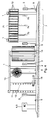
- Figure 1 shows an elevation view of an example of how the system works, in lengthwise cross-section, and in this case, fitted with sensors to detect the vehicle's position, and textile strips for rubbing the bodywork; at the exit, there are a series of mechanisms for spraying rinsing water and de-mineralised water in the form of a curtain.
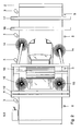
- Figure 2 shows a plan view of the system referred to in figure 1, while a vehicle is being washed.
- Figure 3 shows a block diagram of the control device that is connected to the luminous signals and sensors.
- Figure 4 shows an elevation view of a variation of the system, in lengthwise cross-section, fitted with a grille at the exit zone, for the successive spraying over the whole vehicle of rinsing water, water containing wax additives and de-mineralised water.
- Figure 5 shows a diagrammatic plan view of the system referred to in the preceding figure, while a vehicle is being washed.
- Figure 6 shows a profile view of the end station for rinsing, waxing and rinsing with de-mineralised water, shown in figures 4 and 5.
- In the production example shown in figures 1 to 3, the system is formed by a fixed bridge (1) placed over a track (2) along which the vehicle to be washed is driven. This track is not fitted with any (2) mechanisms that pull the vehicle along and the vehicle is powered by its own engine.
- In this example of how the invention works, the bridge (1) has a set of devices for washing the vehicle through coming into contact with it, consisting of a first set of mechanisms (11) for spraying water onto the body of the vehicle, a set of mechanisms (12) that apply detergent, some mobile textile rollers (13, 14, 15) to clean the upper surface, sides and wheels of the vehicle respectively, a set of mechanisms (16) for spraying rinsing water and a set of mechanisms (17) for spraying de-mineralised water, which leaves no stains or marks on the bodywork, as the vehicle dries after being driven along the road after the wash operation.
- Among the different washing mechanisms or devices (11 to 17) placed on the bridge (1) are some luminous signals (3), for example, traffic lights, to let the driver know when to stop or start moving again, as he drives along the track (2), thereby modifying the movement of the vehicle through the facility.
- These luminous signals (3) are connected to a control device (4), for example a PLC, which can activate successive programmed signals, so that the vehicle takes a certain length of time to travel along the track (2) or, as shown in the example contained in the figures, activate the luminous signals in a controller manner, depending on the information furnished by a set of sensors (5) which detect the vehicle's position on the track (2).
- In this second case, if a vehicle stops on the track (2), the control device (4) will activate the luminous signals behind that vehicle, and activate the luminous signal that prohibits other vehicles from moving forwards until the track is free.
- The control device (4) is also connected to the mechanism (6) that starts up and stops the cleaning mechanisms (11 to 17) on the bridge (1) and to a prepaid machine that automatically makes the system start up controlled by the PLC. In the operation shown in figures 1 to 3, the mechanisms (16, 17) that spray rinsing water and de-mineralised water take are in the form of a bridge, fitted with many different spraying devices aimed at the area where the vehicle passes along, spraying rinsing water and de-mineralised water in the form of curtains.
- As an option, and as shown in figures 4 to 6, the system could have a single station at the exit (7) for rinsing, waxing and rinsing again with de-mineralised water. This end station (7) has a grille (71) of tubular elements connected to each other, fitted with many holes or openings (72) for spraying liquids onto the whole of the vehicle parked at that station.
- A set of conduits (73, 74, 75) are connected to the grille (71) for alternately spraying rinsing water, water containing wax additives and de-mineralised water in sequence and these liquids are sprayed in succession onto the vehicle in the end station described above (7).
- The grille (71) is mounted on the fixed bridge (1) and has a surface that is larger than the vehicles to be washed. The grille (71) sprays the liquids onto the entire vehicle, while it is parked at the end station described above (7).
- To ensure the vehicle remains parked in the end station (7) during the time necessary for rinsing, waxing and rinsing again with de-mineralised water at the exit of that end station (7) a set of luminous signals (3) is in place, to tell the driver when he can leave that station (7).
- Having described the nature of the invention in sufficient detail, and given an example of preferred operation, it is hereby recorded for the opportune purpose that the materials, shape, size and lay-out of the elements described in the preceding paragraphs may be modified, as long as this does not entail any alteration in the essential features of the invention that are being claimed herein.
Claims (8)
- A vehicle wash system, of the type that comprises a fixed bridge (1) placed over a track (2) along which the vehicles to be washed move, this bridge (1) having a series of mechanisms for washing the vehicles that may or may not come into contact with the vehicle, characterised by the fact that it has a set of luminous signals (3) laid out along a track (2) that has no mechanisms for pulling the vehicle along, and a control device (4) that performs selective control over the luminous signals (3) to tell the driver when to stop and when to move forwards along the track, by means of luminous signals.
- A system as described in claim 1, characterised by the fact that it has a series of sensors (5) laid out along the track (2) to detect the position of the vehicles moving along that track (2), and also by the fact that those sensors (5) are connected to the control device (4) that controls the luminous signals (3) and the system operation.
- A system as described in claims 1 or 2, characterised by the fact that the luminous signals (3) consist of traffic lights.
- A system as described in claim 1, characterised by the fact that the washing mechanisms (17) occupying the final position at the exit of the fixed bridge (1) consist of a series of devices that spray de-mineralised water to ensure that the vehicle dries faster without leaving any stains or marks on the body.
- A system as described in claim 1, characterised by the fact that it consists of an end station (7) at the exit of the track (2) for rinsing, waxing and rinsing again with de-mitleralised water. This end station (7) has a grille (71) of pipes connected to each other, fitted with a great many holes and openings (72) for spraying liquids over the vehicle parked in that station; a set of conduits (73, 74, 75) are connected to that grille (71) for the alternate, sequential spraying of water, water containing wax additives and de-mineralised water which is sprayed in succession onto the vehicle parked in the end station described above (7).
- A system, as described in claim 5, characterised by the fact that the grille (71) is mounted on the fixed bridge (1).
- A system, as described in claim 5, characterised by the fact that both the end station (7) and the grille (71) have a surface that is larger than the vehicles to be washed, and this grille (71) sprays liquid all over the entire vehicle.
- Improvements, as described in claim 1, characterised by the fact that one of the luminous signals (3) is placed at the exit of the end station (7).
Applications Claiming Priority (2)
| Application Number | Priority Date | Filing Date | Title |
|---|---|---|---|
| ES200502302A ES2283193B1 (en) | 2005-09-22 | 2005-09-22 | SYSTEM FOR WASHING VEHICLES. |
| ES200502589A ES2292321B1 (en) | 2005-09-22 | 2005-10-25 | PERFECTION IN THE PATENT OF INVENTION 200502302 PER SYSTEM FOR WASHING VEHICLES. |
Publications (2)
| Publication Number | Publication Date |
|---|---|
| EP1767418A2 true EP1767418A2 (en) | 2007-03-28 |
| EP1767418A3 EP1767418A3 (en) | 2007-06-06 |
Family
ID=37402682
Family Applications (1)
| Application Number | Title | Priority Date | Filing Date |
|---|---|---|---|
| EP06019400A Withdrawn EP1767418A3 (en) | 2005-09-22 | 2006-09-15 | Vehicle wash system |
Country Status (1)
| Country | Link |
|---|---|
| EP (1) | EP1767418A3 (en) |
Cited By (5)
| Publication number | Priority date | Publication date | Assignee | Title |
|---|---|---|---|---|
| DE202017102312U1 (en) * | 2017-04-19 | 2018-07-23 | Otto Christ Ag | Treatment road with vehicle position monitoring |
| CN108482322A (en) * | 2018-01-22 | 2018-09-04 | 四川大学 | A kind of method that traffic light intersection carwash mitigates city haze |
| WO2020220822A1 (en) * | 2019-04-30 | 2020-11-05 | 南京林顿自动化设备有限公司 | Car wash control cabinet |
| DE102021102200A1 (en) | 2021-02-01 | 2022-08-04 | Matthias Jäger | Device and method for regularly determining a spatial position of a vehicle, car wash and computer program product |
| US12145546B1 (en) * | 2020-05-15 | 2024-11-19 | National Carwash Solutions, Inc. | Vehicle wash system for washing a vehicle while the car is driven through the vehicle washing system |
Family Cites Families (8)
| Publication number | Priority date | Publication date | Assignee | Title |
|---|---|---|---|---|
| US3579701A (en) * | 1968-06-03 | 1971-05-25 | Clair R Crisp Jr | Automatic car washer |
| US4857113A (en) * | 1985-12-23 | 1989-08-15 | Grace-Lee Products, Inc. | Vehicle cleansing method |
| JP2002516216A (en) * | 1998-05-26 | 2002-06-04 | バッシュテック ホールディング ゲゼルシャフト ミット ベシュレンクテル ハフツング | Vehicle processing equipment and driving method |
| AU5753101A (en) * | 2000-05-08 | 2001-11-20 | Capital Formation Inc | Touch free loading system for an automatic in-bay vehicle wash system |
| US6561202B1 (en) * | 2000-11-09 | 2003-05-13 | Steven Amadio | Extendible side guide poles for car wash |
| JP3750553B2 (en) * | 2001-04-09 | 2006-03-01 | 株式会社ダイフク | Car wash machine |
| TR200300450A2 (en) * | 2003-04-07 | 2004-11-22 | Uzunören Oray | Innovation in automatic car wash machines. |
| US7380558B2 (en) * | 2003-05-28 | 2008-06-03 | Transclean, Inc. | Stationary vehicle cleaning system |
-
2006
- 2006-09-15 EP EP06019400A patent/EP1767418A3/en not_active Withdrawn
Cited By (5)
| Publication number | Priority date | Publication date | Assignee | Title |
|---|---|---|---|---|
| DE202017102312U1 (en) * | 2017-04-19 | 2018-07-23 | Otto Christ Ag | Treatment road with vehicle position monitoring |
| CN108482322A (en) * | 2018-01-22 | 2018-09-04 | 四川大学 | A kind of method that traffic light intersection carwash mitigates city haze |
| WO2020220822A1 (en) * | 2019-04-30 | 2020-11-05 | 南京林顿自动化设备有限公司 | Car wash control cabinet |
| US12145546B1 (en) * | 2020-05-15 | 2024-11-19 | National Carwash Solutions, Inc. | Vehicle wash system for washing a vehicle while the car is driven through the vehicle washing system |
| DE102021102200A1 (en) | 2021-02-01 | 2022-08-04 | Matthias Jäger | Device and method for regularly determining a spatial position of a vehicle, car wash and computer program product |
Also Published As
| Publication number | Publication date |
|---|---|
| EP1767418A3 (en) | 2007-06-06 |
Similar Documents
| Publication | Publication Date | Title |
|---|---|---|
| JP3750553B2 (en) | Car wash machine | |
| EP1767418A2 (en) | Vehicle wash system | |
| CN204801746U (en) | Automatic vehicle washing system | |
| US3300803A (en) | Vehicle washing apparatus | |
| CN208006924U (en) | A kind of quay transportation vehicle chassis cleaning device | |
| US4035862A (en) | In-out automatic vehicle washing apparatus | |
| KR101921311B1 (en) | Car washing system and washing method thereof | |
| JP5018673B2 (en) | Car wash machine | |
| JP5251725B2 (en) | Car wash machine | |
| JP3991834B2 (en) | Car wash method | |
| JP3832925B2 (en) | Car wash equipment | |
| US3626536A (en) | Automatic vehicle washing apparatus | |
| EP1527968A2 (en) | Improved car wash installation and corresponding process for washing | |
| JP3933048B2 (en) | Car wash machine | |
| JP4968108B2 (en) | Car wash equipment | |
| JPH04121258A (en) | Car washer | |
| CN204037518U (en) | A kind of automatic car washing machine | |
| JP5304541B2 (en) | Car wash machine | |
| JP6107736B2 (en) | Car wash machine | |
| KR20030023909A (en) | Apparatus for cleaning tunnel | |
| CN102644394B (en) | Car washing station with advertisement showing function | |
| JP2018103919A (en) | Car wash equipment | |
| JP2005306088A (en) | Car wash machine | |
| US3596242A (en) | Speed warning system | |
| CN110682891A (en) | Trackless automatic car washer |
Legal Events
| Date | Code | Title | Description |
|---|---|---|---|
| PUAI | Public reference made under article 153(3) epc to a published international application that has entered the european phase |
Free format text: ORIGINAL CODE: 0009012 |
|
| 17P | Request for examination filed |
Effective date: 20060915 |
|
| AK | Designated contracting states |
Kind code of ref document: A2 Designated state(s): AT BE BG CH CY CZ DE DK EE ES FI FR GB GR HU IE IS IT LI LT LU LV MC NL PL PT RO SE SI SK TR |
|
| AX | Request for extension of the european patent |
Extension state: AL BA HR MK YU |
|
| RAP1 | Party data changed (applicant data changed or rights of an application transferred) |
Owner name: LAVADOS LAVING, S.A. |
|
| RIN1 | Information on inventor provided before grant (corrected) |
Inventor name: MALAGRIDA MATONS, JAVIER |
|
| PUAL | Search report despatched |
Free format text: ORIGINAL CODE: 0009013 |
|
| AK | Designated contracting states |
Kind code of ref document: A3 Designated state(s): AT BE BG CH CY CZ DE DK EE ES FI FR GB GR HU IE IS IT LI LT LU LV MC NL PL PT RO SE SI SK TR |
|
| AX | Request for extension of the european patent |
Extension state: AL BA HR MK YU |
|
| 17Q | First examination report despatched |
Effective date: 20080107 |
|
| AKX | Designation fees paid |
Designated state(s): AT BE BG CH CY CZ DE DK EE ES FI FR GB GR HU IE IS IT LI LT LU LV MC NL PL PT RO SE SI SK TR |
|
| STAA | Information on the status of an ep patent application or granted ep patent |
Free format text: STATUS: THE APPLICATION IS DEEMED TO BE WITHDRAWN |
|
| 18D | Application deemed to be withdrawn |
Effective date: 20100209 |