EP1767289B2 - Dispositif permettant de guider les barres de coulee - Google Patents
Dispositif permettant de guider les barres de coulee Download PDFInfo
- Publication number
- EP1767289B2 EP1767289B2 EP06018638.4A EP06018638A EP1767289B2 EP 1767289 B2 EP1767289 B2 EP 1767289B2 EP 06018638 A EP06018638 A EP 06018638A EP 1767289 B2 EP1767289 B2 EP 1767289B2
- Authority
- EP
- European Patent Office
- Prior art keywords
- roller
- rollers
- thread
- outer sub
- grooves
- Prior art date
- Legal status (The legal status is an assumption and is not a legal conclusion. Google has not performed a legal analysis and makes no representation as to the accuracy of the status listed.)
- Not-in-force
Links
Images
Classifications
-
- B—PERFORMING OPERATIONS; TRANSPORTING
- B22—CASTING; POWDER METALLURGY
- B22D—CASTING OF METALS; CASTING OF OTHER SUBSTANCES BY THE SAME PROCESSES OR DEVICES
- B22D11/00—Continuous casting of metals, i.e. casting in indefinite lengths
- B22D11/12—Accessories for subsequent treating or working cast stock in situ
- B22D11/128—Accessories for subsequent treating or working cast stock in situ for removing
- B22D11/1287—Rolls; Lubricating, cooling or heating rolls while in use
-
- B—PERFORMING OPERATIONS; TRANSPORTING
- B22—CASTING; POWDER METALLURGY
- B22D—CASTING OF METALS; CASTING OF OTHER SUBSTANCES BY THE SAME PROCESSES OR DEVICES
- B22D11/00—Continuous casting of metals, i.e. casting in indefinite lengths
- B22D11/16—Controlling or regulating processes or operations
- B22D11/22—Controlling or regulating processes or operations for cooling cast stock or mould
- B22D11/225—Controlling or regulating processes or operations for cooling cast stock or mould for secondary cooling
Definitions
- the invention relates to a device for guiding continuous casting profiles or slabs.
- Such devices for guiding continuous casting profiles or slabs are basically known in the prior art. They typically include cooling water means for providing cooling water for cooling the continuous casting profiles or slabs and at least one strand guiding roll for guiding the slabs or continuous casting profiles through the apparatus. From the Japanese patent application JP 61033746 A It is known that such strand guide rollers may have formed a coiled groove on its surface. Furthermore, it is from the Japanese patent application JP 8047757 It is known that such strand guide rollers may have a plurality of adjacent sub-rollers, wherein the surfaces of the sub-rollers may in each case in turn be provided with a groove.
- a strand-guiding roller has a plurality of sub-rollers, there is inevitably a left outer sub-roller, which is assigned to the left-hand edge region of the extruded profile or of the slabs, and a right-outer sub-roller assigned to the right-hand edge region of the slabs.
- the present invention seeks to develop strand guide rollers of a device for guiding continuous casting profiles or slabs in that on the slab surface existing cooling or splash water either either as long as possible on the slab surface or removed as quickly as possible from the slab surface becomes.
- a known apparatus for guiding continuous casting profiles or slabs as described in the introduction, is further developed in that a cooling water means is provided for providing cooling water for cooling the slabs, the groove on the left outer sub-roll and the groove on the right outer sub-roll is formed in the form of a thread and the sign of the pitch of the thread-shaped groove on the left outer part of the role opposite to the sign of the pitch of the thread-shaped groove on the right outer part of the roller is selected.
- the provision of the grooves in the surfaces of the sub-rollers has the advantage that the cooling water can flow out not only in the region of a central bearing between the two outer sub-rollers, but in addition also through the grooves, in particular with a vertical guidance of the slabs.
- This has the advantage that the water drainage channel formed by the distance of the bearing to the surface of the slabs relieves and less cooling water flows through it.
- the thread-shaped design of the groove advantageously causes no water drainage channels to form on the slab surface, because the contact area between the groove and the slab surface transverses with a rotation of the partial rolls transversely to the direction of slab travel.
- this contact region transverse to the slab running direction further has the consequence that the water is not only removed via the grooves, but is also transported by these at least partially in the respective direction of movement of the contact region between the groove and slab surface.
- the parts of the cooling water which do not flow through the grooves or in the area of the camp, but remain as splash water on the slab surface, either to the slab center or transported to the slab edges.
- the claimed opposite signs of the pitches of the thread-shaped grooves on the outer part rollers advantageously allow the splash water from either outer rollers either selectively to the center of the slab out, that is held on the slab surface to continue to cool them or very quickly from the Slab surface is removed, as it may be useful, for example, at the output of the device for guiding continuous casting profiles.
- the strand-guiding roller of the device in addition to the two outer sub-rollers, additionally holds an intermediate roller mounted between them.
- an intermediate roller mounted between them.
- On the surface of this intermediate role is also a groove, in the form of a thread, that is a coiled groove provided to avoid streaking on the slab surface, as in a Nutverlauf with a slope of zero due to the then locally fixed water drainage channel on the Slab surface would result.
- the signs of the pitches of the thread-like grooves on the two outer sub-rollers are chosen so that the contact areas of the grooves with the slab surface in the two outer sub-rollers in the case of rotation of the sub-rollers in the direction of slab center mitwandem. Then, the non-flowing parts of the cooling water are fed to the slab center; that is, the majority of the cooling water is held on the slab surface and is available there for cooling purposes.
- the cooling water is desirable for the cooling water to be removed from the slab surface as quickly as possible.
- This is inventively achieved in that the opposite signs of the pitches of the thread-shaped grooves on the two outer part rollers are chosen so that the contact areas of the grooves with the slabs migrate with a rotation of the outer part rollers each outwardly towards the left and right slab edge. More specifically, then causes the left part of the reel, a discharge of the cooling water over the left edge of the slab and the right part of the role, a discharge of the cooling water over the right edge of the slab.
- the strand guide roll has at least one intermediate roll in the exit area of the continuous casting guide, it is advantageous to have the sign of the pitch of the thread groove on the intermediate roll in an area to the left of the slab center corresponding to the sign of the slope of the groove on the left outer part roll. and in an area to the right of the slab center according to the sign of the slope of the groove on the right outer sub-roll.
- the sign of the pitches of the thread-shaped grooves is selected on these multiple intermediate roles depending on whether the respective intermediate rollers are located to the left or right of the slab center. It is important in this case only that the cooling water is removed as quickly as possible.
- the one intermediate role in the region of the slab center identifies two separate thread-like grooves with different signs of their slopes on their surface.
- strand guide rollers in the exit region of the device to form the outer part rolls and preferably also the intermediate rolls as uniformly as possible with respect to the sign of the pitches of the grooves on their surfaces in order to achieve a fast cooling water drainage to effect.
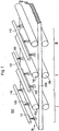
- FIG. 1 shows a device (100) according to the invention, for guiding continuous casting profiles, in particular for slabs 200.
- the slabs or continuous casting profiles run through the device by way of example in the direction of arrow B L.
- the apparatus for guiding continuous casting profiles comprises a cooling water device 110, for example in the form of water nozzles 112, which are arranged between strand guide rollers 130. These nozzles 112 provide cooling water for cooling the slabs.
- the strand guide rollers 130 serve to guide the slabs 200 through the apparatus (100) for guiding continuous casting profiles.
- the slabs are seen in the running direction B L , an input region I, a middle region II and an output region III are distinguished.
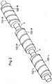
- FIG. 2 shows the typical structure for a strand guide roller 130 according to the invention, as used for example in the apparatus (100) for guiding continuous casting profiles.
- the strand guide roller comprises 130 at least one left outer sub-roll 130-L, which is spatially associated with the left edge of the slab 200, and a right sub-roll 130-R, which is associated with the right edge of the slab 200.
- the strand guide rollers 130 also include a plurality of intermediate rollers 130-M.
- the groove 132-M is also formed thread-shaped to avoid the formation of a stationary water drainage channel, as would occur in a circumferential groove without pitch and a resulting banding on the slab surface.
- the signs of the slopes of the grooves are indeed opposite, but the outer part rollers 130-L, 130-R so assigned that they keep the remaining cooling water, that is, the splash water on the slab surface or merge there.
- the pitches of the thread-like grooves on these intermediate roles are alternating signs.
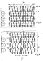
- FIG. 3 shows a segment of a total of 4 parallel strand guide rollers 130, which are each formed from only two sub-rollers, that is, two outer sub-rollers 130-L, 130-R.
- a movement of the slabs 200 in the slab running direction B L results due to the contact of the sub-rollers with the slab surface, a predefined direction of rotation of the sub-rollers.
- the splash water as indicated by the horizontal arrows, out in the direction of slab center.
- the reason for this is that the contact areas K between the groove and the slab surface also move in the direction of the slab center, that is to say in the direction of the arrow.
- FIG. 4 shows the continuation of in FIG. 3 already indicated segment-like interconnection of strand guide rollers in the middle region II and in the end III.
- the strand guide rollers 130 in the middle region II are similarly profiled as in the above-mentioned reason FIG. 3 shown strand guide rollers or their sub-rollers.
- the outer sub-rollers are opposite in shape with respect to the signs of the slopes of their grooves on their surface; moreover, however, the sign of the left outer part roller 130 'is also formed opposite to the sign of the slope grooves on the left outer part roller in the middle area II.
- the right outer part rollers in the outer area III and in the central area II is achieved.
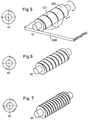
- FIG. 5 shows an example of the formation of a thread-shaped groove 132 on the surface of a strand guide roller 130, that is, in particular on one of the two outer part rollers or an intermediate roller.
- FIG. 5 shows concretely the formation of a catchy groove, wherein FIG. 5a a cross-sectional view and FIG. 5b an elevation view shows.
- FIG. 5b the contact areas K between the groove and the surface of the slabs 200 are illustrated. As mentioned, this contact area moves depending on the direction of rotation of the roller to the left or right edge of the slab.
- FIGS. 6 and 7 show an example of the arrangement of grooves on the roll surface, wherein FIG. 6 a double-course groove course and FIG. 7 describe a three-course groove course. Also in these two figures, the figures a each indicate a cross-section and the figures b each show an elevational view of the multi-start grooves.
- the number of grooves on the outer sub-rollers 130-L, 130-R or on the intermediate rollers and the size of the respective cross-sections of the grooves with respect to the amount to be discharged Cooling water 120 and its uniform distribution on the slab surface selected.
- the number of parallel thread-like grooves per roll that is, the number of flights of the grooves, the widths of the grooves and their pitches on one of the outer part rolls or an intermediate roll 130-M relative to the roll diameter and the roll pitch are made to have a small overlap the contact areas K of two adjacent thread-like grooves on a roll with the slab surface takes place.
Abstract
Description
Die Erfindung betrifft eine Vorrichtung zum Führen von Stranggussprofilen oder Brammen.The invention relates to a device for guiding continuous casting profiles or slabs.
Derartige Vorrichtungen zum Führen von Stranggussprofilen oder Brammen sind im Stand der Technik grundsätzlich bekannt. Sie umfassen typischerweise eine Kühlwassereinrichtung zum Bereitstellen von Kühlwasser zum Kühlen der Stranggussprofile oder Brammen und mindestens eine Strangführungsrolle zum Führen der Brammen oder Stranggussprofile durch die Vorrichtung. Aus der japanischen Patentanmeldung
Ausgehend von diesem Stand der Technik liegt der Erfindung die Aufgabe zugrunde, Strangführungsrollen einer Vorrichtung zum Führen von Stranggussprofilen oder Brammen dahingehend weiterzubilden, dass auf der Brammenoberfläche vorhandenes Kühl- bzw. Schwallwasser wahlweise entweder möglichst lange auf der Brammenoberfläche verbleibt oder möglichst schnell von der Brammenoberfläche abgeführt wird.Based on this prior art, the present invention seeks to develop strand guide rollers of a device for guiding continuous casting profiles or slabs in that on the slab surface existing cooling or splash water either either as long as possible on the slab surface or removed as quickly as possible from the slab surface becomes.
Diese Aufgabe wird durch den Gegenstand des Patentanspruchs 1 gelöst. Demnach wird eine bekannte Vorrichtung zum Führen von Stranggussprofilen oder Brammen, wie sie einleitend beschrieben wurde, dahingehend weitergebildet, dass eine Kühlwassereinrichtung zum Bereitstellen von Kühlwasser zum Kühlen der Brammen vorgesehen ist, die Nut auf der linken äußeren Teilrolle und die Nut auf der rechten äußeren Teilrolle jeweils in Form eines Gewindes ausgebildet ist und das Vorzeichen der Steigung der gewindeförmigen Nut auf der linken äußeren Teilrolle entgegengesetzt zu dem Vorzeichen der Steigung der gewindeförmigen Nut auf der rechten äußeren Teilrolle gewählt ist.This object is solved by the subject matter of patent claim 1. Accordingly, a known apparatus for guiding continuous casting profiles or slabs, as described in the introduction, is further developed in that a cooling water means is provided for providing cooling water for cooling the slabs, the groove on the left outer sub-roll and the groove on the right outer sub-roll is formed in the form of a thread and the sign of the pitch of the thread-shaped groove on the left outer part of the role opposite to the sign of the pitch of the thread-shaped groove on the right outer part of the roller is selected.
Das Vorsehen der Nuten in den Oberflächen der Teilrollen hat insbesondere bei einer vertikalen Führung der Brammen durch die Vorrichtung den Vorteil, dass das Kühlwasser nicht nur im Bereich eines Mittellagers zwischen den beiden äußeren Teilrollen, sondern zusätzlich auch durch die Nuten abfließen kann. Dies hat den Vorteil, dass der durch den Abstand des Lagers zur Oberfläche der Brammen gebildete Wasser-Ablaufkanal entlastet und weniger Kühlwasser dort hindurch abfließt. Die Gewindeförmige Ausbildung der Nut bewirkt vorteilhafterweise, dass sich auf der Brammenoberfläche keine Wasserablaufkanäle bilden, weil der Kontaktbereich zwischen Nut und Brammenoberfläche bei einer Drehung der Teilrollen quer zur Brammenlaufrichtung wandert. Die Wanderung dieses Kontaktbereiches quer zur Brammenlaufrichtung hat weiterhin zur Folge, dass das Wasser nicht nur über die Nuten abgeführt, sondern von diesen auch zumindest teilweise in die jeweilige Bewegungsrichtung des Kontaktbereiches zwischen Nut und Brammenoberfläche transportiert wird. Je nach Drehrichtung der Strangführungsrollen bzw. der Teilrollen und dem Vorzeichen der Steigung der Nuten auf den Teilrollen, werden die Teile des Kühlwassers, die nicht durch die Nuten oder im Bereich des Lagers abfließen, sondern als Schwallwasser auf der Brammenoberfläche verbleiben, entweder zur Brammenmitte oder an die Brammenränder transportiert.The provision of the grooves in the surfaces of the sub-rollers has the advantage that the cooling water can flow out not only in the region of a central bearing between the two outer sub-rollers, but in addition also through the grooves, in particular with a vertical guidance of the slabs. This has the advantage that the water drainage channel formed by the distance of the bearing to the surface of the slabs relieves and less cooling water flows through it. The thread-shaped design of the groove advantageously causes no water drainage channels to form on the slab surface, because the contact area between the groove and the slab surface transverses with a rotation of the partial rolls transversely to the direction of slab travel. The migration of this contact region transverse to the slab running direction further has the consequence that the water is not only removed via the grooves, but is also transported by these at least partially in the respective direction of movement of the contact region between the groove and slab surface. Depending on the direction of rotation of the strand guide rollers or sub-roles and the sign of the slope of the grooves on the sub-rollers, the parts of the cooling water, which do not flow through the grooves or in the area of the camp, but remain as splash water on the slab surface, either to the slab center or transported to the slab edges.
Die beanspruchten entgegengesetzten Vorzeichen der Steigungen der gewindeförmigen Nuten auf den äußeren Teilrollen ermöglichen vorteilhafterweise, dass das Schwallwasser von den beiden äußeren Rollen her wahlweise entweder zur Brammenmitte hin geführt, das heißt auf der Brammenoberfläche gehalten wird, um diese weiterhin zu kühlen oder sehr schnell von der Brammenoberfläche abgeführt wird, wie es zum Beispiel am Ausgang der Vorrichtung zum Führen von Stranggussprofilen sinnvoll sein kann.The claimed opposite signs of the pitches of the thread-shaped grooves on the outer part rollers advantageously allow the splash water from either outer rollers either selectively to the center of the slab out, that is held on the slab surface to continue to cool them or very quickly from the Slab surface is removed, as it may be useful, for example, at the output of the device for guiding continuous casting profiles.
Gemäß der Erfindung fasst die Strangführungsrolle der Vorrichtung neben den beiden äußeren Teilrollen zusätzlich noch eine zwischen ihnen gelagerte Zwischenrolle. Auf der Oberfläche dieser Zwischenrolle ist ebenfalls eine Nut, in Form eines Gewindes, das heißt eine gewendelte Nut vorgesehen, um eine Streifenbildung auf der Brammenoberfläche zu vermeiden, wie sie bei einem Nutverlauf mit einer Steigung von Null aufgrund des dann resultierenden lokal festpositionierten Wasserablaufkanal auf der Brammenoberfläche resultieren würde.According to the invention, the strand-guiding roller of the device, in addition to the two outer sub-rollers, additionally holds an intermediate roller mounted between them. On the surface of this intermediate role is also a groove, in the form of a thread, that is a coiled groove provided to avoid streaking on the slab surface, as in a Nutverlauf with a slope of zero due to the then locally fixed water drainage channel on the Slab surface would result.
In einem Eingangs- oder Mittelbereich der Vorrichtung zum Führen von Stranggussprofilen sind die Vorzeichen der Steigungen der gewindeförmigen Nuten auf den beiden äußeren Teilrollen so gewählt, dass die Kontaktbereiche der Nuten mit der Brammenoberfläche bei den beiden äußeren Teilrollen im Falle einer Drehung der Teilrollen in Richtung Brammenmitte mitwandem. Dann werden auch die nichtabfließenden Teile des Kühlwassers zur Brammenmitte geführt; das heißt der Großteil des Kühlwassers wird auf der Brammenoberfläche gehalten und steht dort für Kühlzwecke zur Verfügung.In an input or central region of the apparatus for guiding continuous casting profiles, the signs of the pitches of the thread-like grooves on the two outer sub-rollers are chosen so that the contact areas of the grooves with the slab surface in the two outer sub-rollers in the case of rotation of the sub-rollers in the direction of slab center mitwandem. Then, the non-flowing parts of the cooling water are fed to the slab center; that is, the majority of the cooling water is held on the slab surface and is available there for cooling purposes.
Sind bei einer Strangführungsrolle im Eingangs- oder Mittelbereich der Vorrichtung zum Führen von Stranggussprofilen mehrere Zwischenrollen vorhanden, so ist es vorteilhaft, wenn die Vorzeichen der Steigungen der gewindeförmigen Nuten auf diesen Zwischenrollen alternierend gewählt sind. Dann wird nicht eine Bewegung des Kühlwassers in eine bevorzugte Richtung quer zur Brammenoberfläche verstärkt, wie dies der Fall wäre, wenn die Vorzeichen auf den Zwischenrollen alle gleich ausgebildet wären; stattdessen wird durch das Alternieren der Vorzeichen bei den Nuten der Zwischenrolle vorteilhafterweise eine gleichmäßigere Verteilung des Kühlwassers auf der Brammenoberfläche bewirkt.If there are a plurality of intermediate rollers in a strand guide roller in the input or central region of the device for guiding continuous casting profiles, then it is advantageous if the signs of the gradients of the thread-shaped grooves on these intermediate rollers are chosen to be alternating. Then, a movement of the cooling water in a preferred direction transverse to the slab surface is not amplified, as would be the case if the signs on the idler rolls were all the same; instead By alternating the signs at the grooves of the intermediate roll advantageously a more even distribution of the cooling water is effected on the slab surface.
Derselbe Vorteil wird auch dadurch erzielt, dass bei zwei benachbarten Strangführungsrollen in dem Eingangs- oder Mittebereich der Vorrichtung zum Führen von Stranggussprofilen mit jeweils gleicher Anzahl von Zwischenrollen die Vorzeichen der Steigungen der gewindeförmigen Nuten von zwei in Brammenlaufrichtung hintereinander angeordneten Zwischenrollen entgegengesetzt gewählt sind.The same advantage is achieved by the fact that in two adjacent strand guide rollers in the input or middle region of the apparatus for guiding continuous casting profiles, each with the same number of intermediate roles, the signs of the pitches of the thread-like grooves of two consecutively arranged in the slab running direction intermediate roles are chosen.
Anders als im Eingangs- und Mittelbereich der Vorrichtung zum Führen von Stranggussprofilen ist es im Ausgangsbereich der Vorrichtung wünschenswert, dass das Kühlwasser so schnell wie möglich von der Brammenoberfläche abgeführt wird. Dies wird erfindungsgemäß dadurch erreicht, dass die entgegengesetzten Vorzeichen der Steigungen der gewindeförmigen Nuten auf den beiden äußeren Teilrollen so gewählt sind, dass die Kontaktbereiche der Nuten mit den Brammen bei einer Drehung der äußeren Teilrollen jeweils nach außen in Richtung linker und rechter Brammenrand wandern. Genauer gesagt bewirkt dann die linke Teilrolle ein Abführen des Kühlwassers über den linken Brammenrand und die rechte Teilrolle ein Abführen des Kühlwassers über den rechten Brammenrand.Unlike the entry and mid-section of the continuous casting guide, in the exit region of the device it is desirable for the cooling water to be removed from the slab surface as quickly as possible. This is inventively achieved in that the opposite signs of the pitches of the thread-shaped grooves on the two outer part rollers are chosen so that the contact areas of the grooves with the slabs migrate with a rotation of the outer part rollers each outwardly towards the left and right slab edge. More specifically, then causes the left part of the reel, a discharge of the cooling water over the left edge of the slab and the right part of the role, a discharge of the cooling water over the right edge of the slab.
Hat die Strangführungsrolle im Ausgangsbereich der Vorrichtung zum Führen von Stranggussprofilen mindestens eine Zwischenrolle, so ist es vorteilhaft, das Vorzeichen der Steigung der gewindeförmigen Nut auf der Zwischenrolle in einem Bereich links von der Brammenmitte entsprechend dem Vorzeichen der Steigung der Nut auf der linken äußeren Teilrolle, und in einem Bereich rechts von der Brammenmitte entsprechend dem Vorzeichen der Steigung der Nut auf der rechten äußeren Teilrolle, zu wählen. Das gilt insbesondere auch dann, wenn mehrere Zwischenrollen vorhanden sind, wobei dann das Vorzeichen der Steigungen der gewindeförmigen Nuten auf diesen mehreren Zwischenrollen in Abhängigkeit davon gewählt wird, ob die jeweiligen Zwischenrollen links oder rechts von der Brammenmitte angeordnet sind. Wichtig ist in diesem Fall lediglich, dass das Kühlwasser möglichst schnell abgeführt wird. Bei Vorhandensein einer ungeraden Anzahl von Zwischenrollen ist es vorteilhaft, wenn die eine Zwischenrolle im Bereich der Brammenmitte zwei getrennte gewindeförmige Nuten mit unterschiedlichen Vorzeichen ihrer Steigungen auf ihrer Oberfläche ausweist.If the strand guide roll has at least one intermediate roll in the exit area of the continuous casting guide, it is advantageous to have the sign of the pitch of the thread groove on the intermediate roll in an area to the left of the slab center corresponding to the sign of the slope of the groove on the left outer part roll. and in an area to the right of the slab center according to the sign of the slope of the groove on the right outer sub-roll. This is especially true when multiple intermediate rollers are present, in which case the sign of the pitches of the thread-shaped grooves is selected on these multiple intermediate roles depending on whether the respective intermediate rollers are located to the left or right of the slab center. It is important in this case only that the cooling water is removed as quickly as possible. In the presence of an odd number of intermediate roles, it is advantageous if the one intermediate role in the region of the slab center identifies two separate thread-like grooves with different signs of their slopes on their surface.
Ebenfalls anders als im Eingangs- oder Mittelbereich der Vorrichtung zum Führen von Stranggussprofilen ist es bei Strangführungsrollen im Ausgangsbereich der Vorrichtung vorteilhaft, die äußeren Teilrollen und vorzugsweise auch die Zwischenrollen hinsichtlich des Vorzeichens der Steigungen der Nuten auf ihren Oberflächen möglichst gleichartig auszubilden, um eine schnelle Kühlwasserabfuhr zu bewirken.Also, unlike in the input or central region of the device for guiding continuous casting profiles, it is advantageous for strand guide rollers in the exit region of the device to form the outer part rolls and preferably also the intermediate rolls as uniformly as possible with respect to the sign of the pitches of the grooves on their surfaces in order to achieve a fast cooling water drainage to effect.
Weitere vorteilhafte Ausgestaltungen der Vorrichtung zum Führen von Stranggussprofilen sind Gegenstand der Unteransprüche.Further advantageous embodiments of the device for guiding continuous casting profiles are the subject of the dependent claims.
Der Beschreibung sind insgesamt 7 Figuren beigefügt, wobei
- Figur 1
- die erfindungsgemäße Vorrichtung zum Führen von Stranggussprofilen;
- Figur 2
- eine Strangführungsrolle mit einer linken und einer rechten äußeren Teilrolle sowie mit einer Zwischenrolle;
- Figur 3
- ein Segment von insgesamt 4 Strangführungsrollen im Eingangs- oder Mittelbereich der Vorrichtung zum Führen von Stranggussprofilen;
- Figur 4
- ein Segment mit zwei Strangführungsrollen im Mittelbereich der Vorrichtung zum Führen von Stranggussprofilen sowie mit zwei Strangführungsrollen im Ausgangsbereich der Vorrichtung
- Figur 5
- ein Beispiel für die Ausbildung einer gewindeförmigen Nut auf der Oberfläche einer Teilrolle in Querschnittsansicht gemäß
Figur 5a und in einer Aufrissansicht gemäßFigur 5b ; - Figur 6
- ein Beispiel für die Ausbildung der gewindeförmigen Nut an der Oberfläche einer Teilrolle in Querschnittsansicht gemäß
Figur 6a und in Aufrissansicht gemäßFigur 6b ; und - Figur 7
- ein Beispiel für die Ausbildung von Nuten auf der Oberfläche einer Teilrolle gemäß der Erfindung, wobei
Figur 7a einen Querschnitt; undFigur 7b eine Aufrissdarstellung der Teilrolle
- FIG. 1
- the inventive device for guiding continuous casting profiles;
- FIG. 2
- a strand guide roller having left and right outer part rollers and an intermediate roller;
- FIG. 3
- a segment of a total of 4 Strandführungsrollen in the input or central region of the device for guiding continuous casting profiles;
- FIG. 4
- a segment with two strand guide rollers in the central region of the device for guiding continuous casting profiles and with two strand guide rollers in the exit region of the device
- FIG. 5
- an example of the formation of a thread-shaped groove on the surface of a sub-roll in cross-sectional view according to
FIG. 5a and in an elevational view according to FIGFIG. 5b ; - FIG. 6
- an example of the formation of the thread-shaped groove on the surface of a partial role in cross-sectional view according to
FIG. 6a and in elevation view according toFIG. 6b ; and - FIG. 7
- an example of the formation of grooves on the surface of a partial roll according to the invention, wherein
Figure 7a a cross section; andFIG. 7b an elevation view of the sub-role
Die Erfindung wird nachfolgend in Form von Ausführungsbeispielen unter Bezugnahme auf die genannten Figuren detailliert beschrieben, wobei nicht alle Figuren sämtliche Merkmale der Erfindung zeigen.The invention will now be described in detail in the form of embodiments with reference to said figures, wherein not all figures show all features of the invention.
Wie in
Wie weiterhin in
Im Eingangsbereich I und dem Mittelbereich II der Vorrichtung 100 sind die Vorzeichen der Steigungen der Nuten zwar entgegengesetzt, aber den äußeren Teilrollen 130-L, 130-R so zugeordnet, dass sie das verbleibende Kühlwasser, das heißt das Schwallwasser, auf der Brammenoberfläche halten bzw. dort zusammenführen. Um eine lokal überdurchschnittlich große Ansammlung von Schwallwasser im Mittelbereich der Brammen zu vermeiden, ist es empfehlenswert bei Vorhandensein mehrerer Zwischenrollen 130-M die Steigungen der gewindeförmigen Nuten auf diesen Zwischenrollen mit alternierenden Vorzeichen auszubilden.In the entrance area I and the central area II of the
In jedem Bereich I, II oder III der Vorrichtung 100 ist es empfehlenswert, dass die Verbindungsbereiche V bzw. die Lager zur Abstützung der Teilrollen in Brammenlaufrichtung BL bei zwei benachbarten Strangführungsrollen nicht fluchten, sondern versetzt angeordnet sind, wie dies in den
Die
Allgemein wird die Anzahl der Nuten auf den äußeren Teilrollen 130-L, 130-R oder auf den Zwischenrollen sowie die Größe der jeweiligen Querschnitte der Nuten im Hinblick auf die Menge des abzuführenden Kühlwassers 120 und dessen gleichmäßige Verteilung auf der Brammenoberfläche gewählt. Weiterhin sind die Anzahl der parallelen gewindeförmigen Nuten pro Rolle, das heißt die Ganganzahl der Nuten, die Breiten der Nuten sowie deren Steigungen auf einer der äußeren Teilrollen oder einer Zwischenrolle 130-M im Verhältnis zum Rollendurchmesser und zur Rollenteilung so ausgeführt, dass eine geringe Überlappung der Kontaktbereiche K von zwei benachbarten gewindeförmigen Nuten auf einer Rolle mit jeweils der Brammenoberfläche stattfindet.In general, the number of grooves on the outer sub-rollers 130-L, 130-R or on the intermediate rollers and the size of the respective cross-sections of the grooves with respect to the amount to be discharged Cooling
Claims (7)
- Device (100) for guiding continuously cast sections or slabs (200), comprising:at least one strip guide roller (130) for guiding the slabs through the device (100), wherein the strip guide roller (130) comprises, distributed over the width of the slabs (200), at least one lefthand outer sub-roller (130-L) associated with the lefthand edge region of the slab and righthand outer sub-roller (130-R) associated with the righthand edge region of the slabs, and wherein at least one groove (132) is formed at each of the surfaces of the two outer sub-rollers (130-L, 130-R), characterised in that a cooling water device (110) for provision of cooling water (12) for cooling the slabs (200) is provided, the groove (132-L) on the lefthand outer sub-roller (130-L) and the groove (132-R) on the righthand outer sub-roller (130-R) are each constructed in the form of a thread, and the sign of the pitch of the thread-shaped groove (132-L) on the lefthand outer sub-roller is selected to be opposite to the sign of the pitch of the thread-shaped groove (132-R) on the righthand outer sub-roller; and at least one intermediate roller (130-M) with at least one groove (132-M) in the form of a thread at its surface is mounted between the lefthand outer sub-roller (130-L) and the righthand outer sub-roller (130-R), wherein the strip guide roller is arranged in an entry region (I) or in a central region (II) of the device (100) for guiding continuously cast sections and the opposite signs of the pitches of the thread-shaped grooves (132-L, 132-R) on the lefthand and righthand outer sub-rollers are so selected that contact regions (K) of the grooves (132) with the slabs (200) migrate in the direction of the slab centre at not only the lefthand, but also the righthand outer sub-roller (130-L, 130-R) during rotation of the sub-rollers.
- Device (100) for guiding continuously cast sections according to claim 1, characterised in that the pitches of the thread-shaped grooves of several intermediate rollers (130-M) present on one and the same strip guide roller are formed with alternating signs.
- Device (100) for guiding continuously cast sections according to claim 2, characterised in that, in the case of two adjacent strip guide rollers (130) in the entry region (I) or centre region (II) of the device (100) each with the same number of intermediate rollers (130-M), the signs of the pitches of the thread-shaped grooves (132-M) of two intermediate rollers arranged in succession in slab running direction (BL) are selected to be opposite.
- Device (100) for guiding continuously cast sections according to any one of the preceding claims, characterised that in that the sub-rollers (130-L, 130-R) and/or the intermediate rollers (130-M) are each supported in the connecting regions (V) thereof by a respective bearing.
- Device (100) for guiding continuously cast sections according to any one of the preceding claims, characterised that in the case of two adjacent strip guide rollers (130) or strip guide rollers (130) arranged in succession in strip running direction (BL) the respective outer sub-rollers, which are arranged in succession, and/or the intermediate rollers are constructed to be of respectively different width.
- Device (100) for guiding continuously cast sections according to any one of the preceding claims, characterised in that the number of grooves on the outer sub-rollers (130-L, 130-R) or the intermediate rollers as well as the size of the respective cross-sections of the grooves are selected to be the same with respect to the amount of cooling water (120) to be conducted away and the uniform distribution thereof on the slab surface.
- Device (100) for guiding continuously cast sections according to any one of the preceding claims, characterised in that the number of parallel thread-shaped grooves per roller, the widths of the respective grooves thereof as well as the pitches thereof on a sub-roller (130-L, 130-R) or an intermediate roller (130-M) are so formed in relation to the roller diameter and to the roller pitch that a small overlap of the contact regions (K) of two adjacent thread-shaped grooves with the slab surface takes place on each occasion.
Applications Claiming Priority (1)
| Application Number | Priority Date | Filing Date | Title |
|---|---|---|---|
| DE102005045838A DE102005045838A1 (en) | 2005-09-24 | 2005-09-24 | cooler |
Publications (4)
| Publication Number | Publication Date |
|---|---|
| EP1767289A2 EP1767289A2 (en) | 2007-03-28 |
| EP1767289A3 EP1767289A3 (en) | 2007-12-26 |
| EP1767289B1 EP1767289B1 (en) | 2009-12-16 |
| EP1767289B2 true EP1767289B2 (en) | 2016-12-14 |
Family
ID=37667625
Family Applications (1)
| Application Number | Title | Priority Date | Filing Date |
|---|---|---|---|
| EP06018638.4A Not-in-force EP1767289B2 (en) | 2005-09-24 | 2006-09-06 | Dispositif permettant de guider les barres de coulee |
Country Status (3)
| Country | Link |
|---|---|
| EP (1) | EP1767289B2 (en) |
| AT (1) | ATE451986T1 (en) |
| DE (2) | DE102005045838A1 (en) |
Families Citing this family (5)
| Publication number | Priority date | Publication date | Assignee | Title |
|---|---|---|---|---|
| EP2481512A1 (en) | 2011-01-26 | 2012-08-01 | Voestalpine Stahl GmbH | Method for producing a roller having a layer made by build up welding ; Roller for guiding and/or supporting a string from a string moulding assembly with such a layer |
| JP2013094828A (en) * | 2011-11-02 | 2013-05-20 | Jfe Steel Corp | Secondary cooling method in continuous casting |
| AT512425A1 (en) * | 2012-01-24 | 2013-08-15 | Siemens Vai Metals Tech Gmbh | ROAD GUIDE ROLLER AND SLIDING GUIDE FOR A CONTINUOUS CASTING MACHINE |
| JP6135616B2 (en) * | 2014-07-31 | 2017-05-31 | Jfeスチール株式会社 | Uniform cooling casting method and continuous casting equipment for continuous cast slab in width direction |
| AT517252B1 (en) | 2015-05-27 | 2019-03-15 | Primetals Technologies Austria GmbH | Avoidance of waterways in a strand guide |
Citations (2)
| Publication number | Priority date | Publication date | Assignee | Title |
|---|---|---|---|---|
| DE1908879A1 (en) † | 1968-02-23 | 1969-10-02 | Us Steel Corp Ges N D Gesetzen | Pinch roller arrangement for continuous casting machines |
| JPH0847757A (en) † | 1994-08-03 | 1996-02-20 | Nippon Steel Corp | Divided roll with groove and device for guiding cast slab and method for guiding cast slab |
Family Cites Families (1)
| Publication number | Priority date | Publication date | Assignee | Title |
|---|---|---|---|---|
| JPS6133746A (en) | 1984-07-27 | 1986-02-17 | Kawasaki Steel Corp | Roll for continuous casting machine |
-
2005
- 2005-09-24 DE DE102005045838A patent/DE102005045838A1/en not_active Withdrawn
-
2006
- 2006-09-06 EP EP06018638.4A patent/EP1767289B2/en not_active Not-in-force
- 2006-09-06 DE DE502006005648T patent/DE502006005648D1/de active Active
- 2006-09-06 AT AT06018638T patent/ATE451986T1/en active
Patent Citations (2)
| Publication number | Priority date | Publication date | Assignee | Title |
|---|---|---|---|---|
| DE1908879A1 (en) † | 1968-02-23 | 1969-10-02 | Us Steel Corp Ges N D Gesetzen | Pinch roller arrangement for continuous casting machines |
| JPH0847757A (en) † | 1994-08-03 | 1996-02-20 | Nippon Steel Corp | Divided roll with groove and device for guiding cast slab and method for guiding cast slab |
Non-Patent Citations (2)
| Title |
|---|
| DUBBEL: "Taschenbuch für den Maschinenbau", vol. 17, 1990, SPRINGER VERLAG † |
| SCHWERDTFEGER K.: "Metallurgie des Stranggiessens - Giessen und Erstarren von Stahl", 1992, VERLAG STAHLEISEN † |
Also Published As
| Publication number | Publication date |
|---|---|
| DE502006005648D1 (en) | 2010-01-28 |
| DE102005045838A1 (en) | 2007-03-29 |
| ATE451986T1 (en) | 2010-01-15 |
| EP1767289A3 (en) | 2007-12-26 |
| EP1767289B1 (en) | 2009-12-16 |
| EP1767289A2 (en) | 2007-03-28 |
Similar Documents
| Publication | Publication Date | Title |
|---|---|---|
| DE2501956C2 (en) | Device for supporting, guiding, bending or straightening and deforming a wide cast strand | |
| EP2303491B1 (en) | Modular strand guide roller | |
| EP1767289B2 (en) | Dispositif permettant de guider les barres de coulee | |
| DE2612714A1 (en) | DEVICE FOR DIVISION OF ROLLED METAL STUDS AND FORMATION OF MULTIPLE BAR MATERIAL | |
| AT3953U2 (en) | STRING GUIDING ELEMENT AND STRING GUIDING SEGMENT WITH INTEGRATED STRING GUIDING ELEMENT | |
| DE2522070A1 (en) | ROLLED GOODS GUIDE FOR A ROLLING STAND | |
| DE3209890A1 (en) | Pickling line for the continuous pickling of metal strips | |
| DE19743093C1 (en) | Production of a metal strip with regions of different thickness over its width | |
| DE3103608A1 (en) | METHOD FOR PRODUCING METAL WIRE | |
| DE2503494C2 (en) | Strand guide frame in a continuous caster | |
| DE8501065U1 (en) | Device for feeding strands to a folder | |
| EP1449958B1 (en) | Device for the treatment, in particular for low pressure treatment, of the wire or felt of a papermachine | |
| DE2447504C3 (en) | Device for holding and guiding a strand in at least part of a secondary cooling zone of a strand | |
| DE102004014264B3 (en) | Layers for fast-moving wire rod coming from a wire rod mill | |
| DE2144082C3 (en) | Method and device for supporting and guiding a steel strand emerging from a continuous casting mold | |
| DE102022202362A1 (en) | Arch segment of a strand guide device | |
| DE1461054B1 (en) | Paper machine | |
| DE2736099C2 (en) | Continuously working press | |
| DE2325428C3 (en) | Roller arrangement on presses for dewatering moist fibrous materials | |
| DE2705397A1 (en) | METHOD OF MANUFACTURING LONG EXTENDED METAL RODS BY SPLITTING MULTI-STRANDED RODS | |
| DE1461054C (en) | Paper machine | |
| DE1402679A1 (en) | Switch in wire and fine iron lines | |
| AT153239B (en) | String forming device for string cigarette machines. | |
| AT257519B (en) | Drum cooling bed for long rolling stock | |
| DE2455C (en) | Strip iron rolling mill with alternating vertical and horizontal pairs of caliber rollers |
Legal Events
| Date | Code | Title | Description |
|---|---|---|---|
| PUAI | Public reference made under article 153(3) epc to a published international application that has entered the european phase |
Free format text: ORIGINAL CODE: 0009012 |
|
| 17P | Request for examination filed |
Effective date: 20060906 |
|
| AK | Designated contracting states |
Kind code of ref document: A2 Designated state(s): AT BE BG CH CY CZ DE DK EE ES FI FR GB GR HU IE IS IT LI LT LU LV MC NL PL PT RO SE SI SK TR |
|
| AX | Request for extension of the european patent |
Extension state: AL BA HR MK YU |
|
| PUAL | Search report despatched |
Free format text: ORIGINAL CODE: 0009013 |
|
| AK | Designated contracting states |
Kind code of ref document: A3 Designated state(s): AT BE BG CH CY CZ DE DK EE ES FI FR GB GR HU IE IS IT LI LT LU LV MC NL PL PT RO SE SI SK TR |
|
| AX | Request for extension of the european patent |
Extension state: AL BA HR MK YU |
|
| RIC1 | Information provided on ipc code assigned before grant |
Ipc: B22D 11/128 20060101AFI20070130BHEP Ipc: B21B 27/00 20060101ALI20071121BHEP Ipc: B22D 11/22 20060101ALI20071121BHEP |
|
| AKX | Designation fees paid |
Designated state(s): AT BE BG CH CY CZ DE DK EE ES FI FR GB GR HU IE IS IT LI LT LU LV MC NL PL PT RO SE SI SK TR |
|
| 17Q | First examination report despatched |
Effective date: 20080821 |
|
| RAP1 | Party data changed (applicant data changed or rights of an application transferred) |
Owner name: SMS SIEMAG AG |
|
| GRAP | Despatch of communication of intention to grant a patent |
Free format text: ORIGINAL CODE: EPIDOSNIGR1 |
|
| RTI1 | Title (correction) |
Free format text: DISPOSITIF PERMETTANT DE GUIDER LES BARRES DE COULEE |
|
| GRAS | Grant fee paid |
Free format text: ORIGINAL CODE: EPIDOSNIGR3 |
|
| GRAA | (expected) grant |
Free format text: ORIGINAL CODE: 0009210 |
|
| AK | Designated contracting states |
Kind code of ref document: B1 Designated state(s): AT BE BG CH CY CZ DE DK EE ES FI FR GB GR HU IE IS IT LI LT LU LV MC NL PL PT RO SE SI SK TR |
|
| REG | Reference to a national code |
Ref country code: GB Ref legal event code: FG4D Free format text: NOT ENGLISH |
|
| REG | Reference to a national code |
Ref country code: CH Ref legal event code: EP |
|
| REG | Reference to a national code |
Ref country code: IE Ref legal event code: FG4D |
|
| REF | Corresponds to: |
Ref document number: 502006005648 Country of ref document: DE Date of ref document: 20100128 Kind code of ref document: P |
|
| REG | Reference to a national code |
Ref country code: NL Ref legal event code: VDEP Effective date: 20091216 |
|
| PG25 | Lapsed in a contracting state [announced via postgrant information from national office to epo] |
Ref country code: SE Free format text: LAPSE BECAUSE OF FAILURE TO SUBMIT A TRANSLATION OF THE DESCRIPTION OR TO PAY THE FEE WITHIN THE PRESCRIBED TIME-LIMIT Effective date: 20091216 Ref country code: LT Free format text: LAPSE BECAUSE OF FAILURE TO SUBMIT A TRANSLATION OF THE DESCRIPTION OR TO PAY THE FEE WITHIN THE PRESCRIBED TIME-LIMIT Effective date: 20091216 Ref country code: FI Free format text: LAPSE BECAUSE OF FAILURE TO SUBMIT A TRANSLATION OF THE DESCRIPTION OR TO PAY THE FEE WITHIN THE PRESCRIBED TIME-LIMIT Effective date: 20091216 |
|
| LTIE | Lt: invalidation of european patent or patent extension |
Effective date: 20091216 |
|
| PG25 | Lapsed in a contracting state [announced via postgrant information from national office to epo] |
Ref country code: SI Free format text: LAPSE BECAUSE OF FAILURE TO SUBMIT A TRANSLATION OF THE DESCRIPTION OR TO PAY THE FEE WITHIN THE PRESCRIBED TIME-LIMIT Effective date: 20091216 Ref country code: PL Free format text: LAPSE BECAUSE OF FAILURE TO SUBMIT A TRANSLATION OF THE DESCRIPTION OR TO PAY THE FEE WITHIN THE PRESCRIBED TIME-LIMIT Effective date: 20091216 Ref country code: LV Free format text: LAPSE BECAUSE OF FAILURE TO SUBMIT A TRANSLATION OF THE DESCRIPTION OR TO PAY THE FEE WITHIN THE PRESCRIBED TIME-LIMIT Effective date: 20091216 |
|
| REG | Reference to a national code |
Ref country code: IE Ref legal event code: FD4D |
|
| PG25 | Lapsed in a contracting state [announced via postgrant information from national office to epo] |
Ref country code: PT Free format text: LAPSE BECAUSE OF FAILURE TO SUBMIT A TRANSLATION OF THE DESCRIPTION OR TO PAY THE FEE WITHIN THE PRESCRIBED TIME-LIMIT Effective date: 20100416 Ref country code: IE Free format text: LAPSE BECAUSE OF FAILURE TO SUBMIT A TRANSLATION OF THE DESCRIPTION OR TO PAY THE FEE WITHIN THE PRESCRIBED TIME-LIMIT Effective date: 20091216 Ref country code: NL Free format text: LAPSE BECAUSE OF FAILURE TO SUBMIT A TRANSLATION OF THE DESCRIPTION OR TO PAY THE FEE WITHIN THE PRESCRIBED TIME-LIMIT Effective date: 20091216 Ref country code: EE Free format text: LAPSE BECAUSE OF FAILURE TO SUBMIT A TRANSLATION OF THE DESCRIPTION OR TO PAY THE FEE WITHIN THE PRESCRIBED TIME-LIMIT Effective date: 20091216 Ref country code: BG Free format text: LAPSE BECAUSE OF FAILURE TO SUBMIT A TRANSLATION OF THE DESCRIPTION OR TO PAY THE FEE WITHIN THE PRESCRIBED TIME-LIMIT Effective date: 20100316 Ref country code: RO Free format text: LAPSE BECAUSE OF FAILURE TO SUBMIT A TRANSLATION OF THE DESCRIPTION OR TO PAY THE FEE WITHIN THE PRESCRIBED TIME-LIMIT Effective date: 20091216 Ref country code: ES Free format text: LAPSE BECAUSE OF FAILURE TO SUBMIT A TRANSLATION OF THE DESCRIPTION OR TO PAY THE FEE WITHIN THE PRESCRIBED TIME-LIMIT Effective date: 20100327 Ref country code: IS Free format text: LAPSE BECAUSE OF FAILURE TO SUBMIT A TRANSLATION OF THE DESCRIPTION OR TO PAY THE FEE WITHIN THE PRESCRIBED TIME-LIMIT Effective date: 20100416 |
|
| PG25 | Lapsed in a contracting state [announced via postgrant information from national office to epo] |
Ref country code: CZ Free format text: LAPSE BECAUSE OF FAILURE TO SUBMIT A TRANSLATION OF THE DESCRIPTION OR TO PAY THE FEE WITHIN THE PRESCRIBED TIME-LIMIT Effective date: 20091216 Ref country code: SK Free format text: LAPSE BECAUSE OF FAILURE TO SUBMIT A TRANSLATION OF THE DESCRIPTION OR TO PAY THE FEE WITHIN THE PRESCRIBED TIME-LIMIT Effective date: 20091216 |
|
| PLBI | Opposition filed |
Free format text: ORIGINAL CODE: 0009260 |
|
| 26 | Opposition filed |
Opponent name: SIEMENS VAI METALS TECHNOLOGIES GMBH Effective date: 20100913 |
|
| PLAX | Notice of opposition and request to file observation + time limit sent |
Free format text: ORIGINAL CODE: EPIDOSNOBS2 |
|
| PG25 | Lapsed in a contracting state [announced via postgrant information from national office to epo] |
Ref country code: GR Free format text: LAPSE BECAUSE OF FAILURE TO SUBMIT A TRANSLATION OF THE DESCRIPTION OR TO PAY THE FEE WITHIN THE PRESCRIBED TIME-LIMIT Effective date: 20100317 Ref country code: CY Free format text: LAPSE BECAUSE OF FAILURE TO SUBMIT A TRANSLATION OF THE DESCRIPTION OR TO PAY THE FEE WITHIN THE PRESCRIBED TIME-LIMIT Effective date: 20091216 |
|
| PG25 | Lapsed in a contracting state [announced via postgrant information from national office to epo] |
Ref country code: DK Free format text: LAPSE BECAUSE OF FAILURE TO SUBMIT A TRANSLATION OF THE DESCRIPTION OR TO PAY THE FEE WITHIN THE PRESCRIBED TIME-LIMIT Effective date: 20091216 |
|
| PLAF | Information modified related to communication of a notice of opposition and request to file observations + time limit |
Free format text: ORIGINAL CODE: EPIDOSCOBS2 |
|
| BERE | Be: lapsed |
Owner name: SMS SIEMAG AG Effective date: 20100930 |
|
| PG25 | Lapsed in a contracting state [announced via postgrant information from national office to epo] |
Ref country code: MC Free format text: LAPSE BECAUSE OF NON-PAYMENT OF DUE FEES Effective date: 20100930 |
|
| REG | Reference to a national code |
Ref country code: CH Ref legal event code: PL |
|
| PLBB | Reply of patent proprietor to notice(s) of opposition received |
Free format text: ORIGINAL CODE: EPIDOSNOBS3 |
|
| REG | Reference to a national code |
Ref country code: FR Ref legal event code: ST Effective date: 20110531 |
|
| PG25 | Lapsed in a contracting state [announced via postgrant information from national office to epo] |
Ref country code: FR Free format text: LAPSE BECAUSE OF NON-PAYMENT OF DUE FEES Effective date: 20100930 Ref country code: BE Free format text: LAPSE BECAUSE OF NON-PAYMENT OF DUE FEES Effective date: 20100930 Ref country code: CH Free format text: LAPSE BECAUSE OF NON-PAYMENT OF DUE FEES Effective date: 20100930 Ref country code: LI Free format text: LAPSE BECAUSE OF NON-PAYMENT OF DUE FEES Effective date: 20100930 |
|
| PG25 | Lapsed in a contracting state [announced via postgrant information from national office to epo] |
Ref country code: HU Free format text: LAPSE BECAUSE OF FAILURE TO SUBMIT A TRANSLATION OF THE DESCRIPTION OR TO PAY THE FEE WITHIN THE PRESCRIBED TIME-LIMIT Effective date: 20100617 Ref country code: LU Free format text: LAPSE BECAUSE OF NON-PAYMENT OF DUE FEES Effective date: 20100906 |
|
| PG25 | Lapsed in a contracting state [announced via postgrant information from national office to epo] |
Ref country code: TR Free format text: LAPSE BECAUSE OF FAILURE TO SUBMIT A TRANSLATION OF THE DESCRIPTION OR TO PAY THE FEE WITHIN THE PRESCRIBED TIME-LIMIT Effective date: 20091216 |
|
| PGFP | Annual fee paid to national office [announced via postgrant information from national office to epo] |
Ref country code: GB Payment date: 20120920 Year of fee payment: 7 |
|
| RDAF | Communication despatched that patent is revoked |
Free format text: ORIGINAL CODE: EPIDOSNREV1 |
|
| APBM | Appeal reference recorded |
Free format text: ORIGINAL CODE: EPIDOSNREFNO |
|
| APBP | Date of receipt of notice of appeal recorded |
Free format text: ORIGINAL CODE: EPIDOSNNOA2O |
|
| APAH | Appeal reference modified |
Free format text: ORIGINAL CODE: EPIDOSCREFNO |
|
| APAW | Appeal reference deleted |
Free format text: ORIGINAL CODE: EPIDOSDREFNO |
|
| APAY | Date of receipt of notice of appeal deleted |
Free format text: ORIGINAL CODE: EPIDOSDNOA2O |
|
| APBM | Appeal reference recorded |
Free format text: ORIGINAL CODE: EPIDOSNREFNO |
|
| APBP | Date of receipt of notice of appeal recorded |
Free format text: ORIGINAL CODE: EPIDOSNNOA2O |
|
| PGFP | Annual fee paid to national office [announced via postgrant information from national office to epo] |
Ref country code: IT Payment date: 20120925 Year of fee payment: 7 |
|
| PGFP | Annual fee paid to national office [announced via postgrant information from national office to epo] |
Ref country code: AT Payment date: 20120912 Year of fee payment: 7 |
|
| APBQ | Date of receipt of statement of grounds of appeal recorded |
Free format text: ORIGINAL CODE: EPIDOSNNOA3O |
|
| REG | Reference to a national code |
Ref country code: AT Ref legal event code: MM01 Ref document number: 451986 Country of ref document: AT Kind code of ref document: T Effective date: 20130906 |
|
| GBPC | Gb: european patent ceased through non-payment of renewal fee |
Effective date: 20130906 |
|
| PG25 | Lapsed in a contracting state [announced via postgrant information from national office to epo] |
Ref country code: GB Free format text: LAPSE BECAUSE OF NON-PAYMENT OF DUE FEES Effective date: 20130906 |
|
| PG25 | Lapsed in a contracting state [announced via postgrant information from national office to epo] |
Ref country code: AT Free format text: LAPSE BECAUSE OF NON-PAYMENT OF DUE FEES Effective date: 20130906 Ref country code: IT Free format text: LAPSE BECAUSE OF NON-PAYMENT OF DUE FEES Effective date: 20130906 |
|
| RAP2 | Party data changed (patent owner data changed or rights of a patent transferred) |
Owner name: SMS GROUP GMBH |
|
| REG | Reference to a national code |
Ref country code: DE Ref legal event code: R082 Ref document number: 502006005648 Country of ref document: DE Representative=s name: HEMMERICH & KOLLEGEN, DE Ref country code: DE Ref legal event code: R081 Ref document number: 502006005648 Country of ref document: DE Owner name: SMS GROUP GMBH, DE Free format text: FORMER OWNER: SMS SIEMAG AG, 40237 DUESSELDORF, DE |
|
| PLAB | Opposition data, opponent's data or that of the opponent's representative modified |
Free format text: ORIGINAL CODE: 0009299OPPO |
|
| R26 | Opposition filed (corrected) |
Opponent name: PRIMETALS TECHNOLOGIES AUSTRIA GMBH Effective date: 20100913 |
|
| APBU | Appeal procedure closed |
Free format text: ORIGINAL CODE: EPIDOSNNOA9O |
|
| PUAH | Patent maintained in amended form |
Free format text: ORIGINAL CODE: 0009272 |
|
| STAA | Information on the status of an ep patent application or granted ep patent |
Free format text: STATUS: PATENT MAINTAINED AS AMENDED |
|
| 27A | Patent maintained in amended form |
Effective date: 20161214 |
|
| AK | Designated contracting states |
Kind code of ref document: B2 Designated state(s): AT BE BG CH CY CZ DE DK EE ES FI FR GB GR HU IE IS IT LI LT LU LV MC NL PL PT RO SE SI SK TR |
|
| REG | Reference to a national code |
Ref country code: DE Ref legal event code: R102 Ref document number: 502006005648 Country of ref document: DE |
|
| PG25 | Lapsed in a contracting state [announced via postgrant information from national office to epo] |
Ref country code: LV Free format text: LAPSE BECAUSE OF FAILURE TO SUBMIT A TRANSLATION OF THE DESCRIPTION OR TO PAY THE FEE WITHIN THE PRESCRIBED TIME-LIMIT Effective date: 20161214 |
|
| PGFP | Annual fee paid to national office [announced via postgrant information from national office to epo] |
Ref country code: DE Payment date: 20200925 Year of fee payment: 15 |
|
| REG | Reference to a national code |
Ref country code: DE Ref legal event code: R119 Ref document number: 502006005648 Country of ref document: DE |
|
| PG25 | Lapsed in a contracting state [announced via postgrant information from national office to epo] |
Ref country code: DE Free format text: LAPSE BECAUSE OF NON-PAYMENT OF DUE FEES Effective date: 20220401 |