EP1766463B1 - Multianzeigesystem und überwachungsverfahren dazu - Google Patents
Multianzeigesystem und überwachungsverfahren dazu Download PDFInfo
- Publication number
- EP1766463B1 EP1766463B1 EP05744923.3A EP05744923A EP1766463B1 EP 1766463 B1 EP1766463 B1 EP 1766463B1 EP 05744923 A EP05744923 A EP 05744923A EP 1766463 B1 EP1766463 B1 EP 1766463B1
- Authority
- EP
- European Patent Office
- Prior art keywords
- backlight
- display
- state
- defective
- signal
- Prior art date
- Legal status (The legal status is an assumption and is not a legal conclusion. Google has not performed a legal analysis and makes no representation as to the accuracy of the status listed.)
- Expired - Lifetime
Links
Images


Classifications
-
- G—PHYSICS
- G02—OPTICS
- G02F—OPTICAL DEVICES OR ARRANGEMENTS FOR THE CONTROL OF LIGHT BY MODIFICATION OF THE OPTICAL PROPERTIES OF THE MEDIA OF THE ELEMENTS INVOLVED THEREIN; NON-LINEAR OPTICS; FREQUENCY-CHANGING OF LIGHT; OPTICAL LOGIC ELEMENTS; OPTICAL ANALOGUE/DIGITAL CONVERTERS
- G02F1/00—Devices or arrangements for the control of the intensity, colour, phase, polarisation or direction of light arriving from an independent light source, e.g. switching, gating or modulating; Non-linear optics
- G02F1/01—Devices or arrangements for the control of the intensity, colour, phase, polarisation or direction of light arriving from an independent light source, e.g. switching, gating or modulating; Non-linear optics for the control of the intensity, phase, polarisation or colour
- G02F1/13—Devices or arrangements for the control of the intensity, colour, phase, polarisation or direction of light arriving from an independent light source, e.g. switching, gating or modulating; Non-linear optics for the control of the intensity, phase, polarisation or colour based on liquid crystals, e.g. single liquid crystal display cells
- G02F1/133—Constructional arrangements; Operation of liquid crystal cells; Circuit arrangements
-
- G—PHYSICS
- G06—COMPUTING OR CALCULATING; COUNTING
- G06F—ELECTRIC DIGITAL DATA PROCESSING
- G06F3/00—Input arrangements for transferring data to be processed into a form capable of being handled by the computer; Output arrangements for transferring data from processing unit to output unit, e.g. interface arrangements
- G06F3/14—Digital output to display device ; Cooperation and interconnection of the display device with other functional units
- G06F3/1423—Digital output to display device ; Cooperation and interconnection of the display device with other functional units controlling a plurality of local displays, e.g. CRT and flat panel display
- G06F3/1431—Digital output to display device ; Cooperation and interconnection of the display device with other functional units controlling a plurality of local displays, e.g. CRT and flat panel display using a single graphics controller
-
- G—PHYSICS
- G09—EDUCATION; CRYPTOGRAPHY; DISPLAY; ADVERTISING; SEALS
- G09G—ARRANGEMENTS OR CIRCUITS FOR CONTROL OF INDICATING DEVICES USING STATIC MEANS TO PRESENT VARIABLE INFORMATION
- G09G3/00—Control arrangements or circuits, of interest only in connection with visual indicators other than cathode-ray tubes
- G09G3/20—Control arrangements or circuits, of interest only in connection with visual indicators other than cathode-ray tubes for presentation of an assembly of a number of characters, e.g. a page, by composing the assembly by combination of individual elements arranged in a matrix no fixed position being assigned to or needed to be assigned to the individual characters or partial characters
- G09G3/34—Control arrangements or circuits, of interest only in connection with visual indicators other than cathode-ray tubes for presentation of an assembly of a number of characters, e.g. a page, by composing the assembly by combination of individual elements arranged in a matrix no fixed position being assigned to or needed to be assigned to the individual characters or partial characters by control of light from an independent source
- G09G3/3406—Control of illumination source
-
- H—ELECTRICITY
- H05—ELECTRIC TECHNIQUES NOT OTHERWISE PROVIDED FOR
- H05B—ELECTRIC HEATING; ELECTRIC LIGHT SOURCES NOT OTHERWISE PROVIDED FOR; CIRCUIT ARRANGEMENTS FOR ELECTRIC LIGHT SOURCES, IN GENERAL
- H05B47/00—Circuit arrangements for operating light sources in general, i.e. where the type of light source is not relevant
- H05B47/20—Responsive to malfunctions or to light source life; for protection
-
- H—ELECTRICITY
- H05—ELECTRIC TECHNIQUES NOT OTHERWISE PROVIDED FOR
- H05B—ELECTRIC HEATING; ELECTRIC LIGHT SOURCES NOT OTHERWISE PROVIDED FOR; CIRCUIT ARRANGEMENTS FOR ELECTRIC LIGHT SOURCES, IN GENERAL
- H05B47/00—Circuit arrangements for operating light sources in general, i.e. where the type of light source is not relevant
- H05B47/20—Responsive to malfunctions or to light source life; for protection
- H05B47/21—Responsive to malfunctions or to light source life; for protection of two or more light sources connected in parallel
- H05B47/22—Responsive to malfunctions or to light source life; for protection of two or more light sources connected in parallel with communication between the lamps and a central unit
-
- G—PHYSICS
- G09—EDUCATION; CRYPTOGRAPHY; DISPLAY; ADVERTISING; SEALS
- G09G—ARRANGEMENTS OR CIRCUITS FOR CONTROL OF INDICATING DEVICES USING STATIC MEANS TO PRESENT VARIABLE INFORMATION
- G09G2330/00—Aspects of power supply; Aspects of display protection and defect management
- G09G2330/08—Fault-tolerant or redundant circuits, or circuits in which repair of defects is prepared
-
- G—PHYSICS
- G09—EDUCATION; CRYPTOGRAPHY; DISPLAY; ADVERTISING; SEALS
- G09G—ARRANGEMENTS OR CIRCUITS FOR CONTROL OF INDICATING DEVICES USING STATIC MEANS TO PRESENT VARIABLE INFORMATION
- G09G2370/00—Aspects of data communication
- G09G2370/04—Exchange of auxiliary data, i.e. other than image data, between monitor and graphics controller
Definitions
- the present general inventive concept relates to a multi-display system and a control method thereof, and more particularly, to a multi-display system and a control method thereof providing a host device to readily detect a defective backlight in each of a plurality of display apparatuses.
- an airport or a train station displays information about flight schedules or departure/arrival schedules using a plurality of display apparatuses such as a giant liquid crystal display (LCD) monitor or a plasma display panel (PDP) monitor, and these display apparatuses are called a vertical market business (VMB) model.
- LCD giant liquid crystal display
- PDP plasma display panel
- a common LCD monitor requires four backlights, and thus it is easy to detect a defect backlight because the LCD monitor displays a dark screen if one of the backlights is turned off, but the giant LCD monitor as the VMB model needs a plurality of backlights, and thus it is difficult to detect the defective backlight because one defective backlight out of the plurality of defect-free backlights does not make any visible difference.
- a multi-display system in accordance with the preamble of claim 1 is known from US 2002/167637 A1 .
- the present invention provides a multi-display system as defined in claim 1.
- the invention further provides a method for controlling this multi-display system as defined in claim 2.
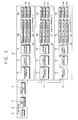
- a multi-display system may comprise a host device 10 comprising a display 12, a communication part 14, and a host controller 16; and a plurality of display apparatuses 30, 40 and 50 respectively comprising a communication interface 32, 42 and 52, a plurality of backlights 34a, 34b, 34c, 44a, 44b, 44c, 54a, 54b and 54c, a plurality of backlight state detectors 36a, 36b, 36c, 46a, 46b, 46c, 56a, 56b and 56c corresponding to the respective backlights 34a, 34b, 34c, 44a, 44b, 44c, 54a, 54b, and 54c to detect a defective state (or target state) of the respective backlights 34a, 34b, 34c, 44a, 44b, 44c, 54a, 54b and 54c, an interrupt signal generator 39, 49 and 59 to generate an interrupt signal, and a display controller 38, 48 and 58.
- the communication part 14 in the host device 10 and the communication interfaces 32, 42 and 52 in the display apparatuses 30, 40 and 50 may adopt an RS-232C interface, however other wired/wireless interfaces may also be adopted.
- One communication interface 32 among the plural communication interfaces 32, 42 and 52 (hereinafter, referred to as "first interface,” “second interface” and “third interface,” respectively) respectively associated with the plurality of display apparatuses 30, 40 and 50 (hereinafter, referred to as “first display”, “second display” and “third display,” respectively) can be connected to the communication part 14 in the host device 10 and can thus directly communicate data with the host device 10.
- the first interface 32 of the first display 30 connected to the host device 10 can be connected to the second interface 42 of the second display 40, and the second interface 42 can be connected to the third interface 52 of the third display 50.
- each of the first, second and third displays 30, 40 and 50 can be connected by a loop-out RS232C circuit.
- a configurational aspect of the present general inventive concept is not limited to the foregoing configurational structure.
- the host device 10 and the display apparatuses 30, 40 and 50 may communicate with each other through various configurational structures.
- the backlights 34a, 34b, 34c, 44a, 44b, 44c, 54a, 54b and 54c supply light to a display panel of the first, second and third displays 30, 40 and 50, and each display panel comprises a non-emissive display device, such as a liquid crystal display (LCD).
- a non-emissive display device such as a liquid crystal display (LCD).
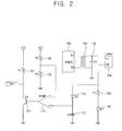
- FIG. 2 is a detailed circuit diagram of one backlight state detector 36a of the plurality of backlight state detectors 36a, 36b, 36c, 46a, 46b, 46c, 56a, 56b and 56c corresponding to one backlight 34a of the plurality of backlights 34a, 34b, 34c, 44a, 44b, 44c, 54a, 54b and 54c.
- all of the plurality of backlight state detectors 36a, 36b, 36c, 46a, 46b, 46c, 56a, 56b and 56c corresponding to the plurality of backlights 34a, 34b, 34c, 44a, 44b, 44c, 54a, 54b and 54c can be configured similarly.
- a driving power can be applied to the backlight 34a as follows.
- a power supplier 100 can supply a voltage to a primary coil of a transformer 102, and thus a high voltage can be introduced to a secondary coil of the transformer 102.
- the high voltage introduced to the secondary coil of the transformer 102 can be applied to a capacitor 104 to output an alternating current (AC) voltage to the backlight 34a through a terminal P1 to thereby turn on the backlight 34a.
- AC alternating current
- the backlight state detector 36a detects the backlight 34a to detect the defective state of the backlight 34a, and will be described in detail referring to FIG. 2 .
- the backlight state detector 36a may comprise an AC-DC converter to convert the alternating current voltage output from a terminal P2 of the backlight 34a into a direct current (DC) voltage, a reference voltage supplier to supply a predetermined reference voltage, a comparator 114 to compare the direct current voltage output from the AC-DC converter with the reference voltage and to output a comparing result signal in response thereto, and a switch 122 to generate a backlight state detecting signal by being selectively turned on or off according to the comparing result signal from the comparator 114.
- DC direct current
- the AC-DC converter may comprise a diode 110 to rectify the alternating current voltage output through the backlight 34a, and a capacitor 112 to smooth the voltage rectified by the diode 110. If the backlight -34a is defect-free, the direct current voltage output from the AC-DC converter becomes higher than a predetermined voltage level. On the other hand, if the backlight 34a is defective, the direct current voltage output from the AC-DC converter is decreased to a ground level, for example, and thus becomes lower than the predetermined voltage level.
- the AC-DC converter may further comprise a resistor 106 and a diode 108 to protect the diode 110 and/or the comparator 114 from a high voltage.
- the reference voltage supplier may comprise a circuit designed to divide a Vcc voltage by resistors R2 and R3 116 and 118 which absorb the Vcc voltage and to thereby apply a given DC voltage as the reference voltage.
- Vref Vcc ⁇ R ⁇ 3 R ⁇ 2 + R ⁇ 3
- the reference voltage can be set lower than the DC voltage output from the AC-DC converter if the backlight 34a is defect-free, and higher than the DC voltage output from the AC-DC converter if the backlight 34a is defective.
- the comparator 114 may comprise an operational amplifier (OP-AMP) having a positive terminal at one end thereof to receive the DC voltage output from the AC-DC converter and a negative terminal at the other end thereof to receive the reference voltage supplied by the reference voltage supplier.
- OP-AMP operational amplifier
- the input voltages of the positive terminal and the negative terminal may be switched, however, so that the DC voltage from the AC_DC converter can be received at the negative terminal and the reference voltage can be received at the positive terminal.
- the DC voltage applied to the positive terminal of the comparator 114 is higher than the reference voltage applied to the negative terminal of the comparator 114, and accordingly the comparator 114 generates a high signal.
- the DC voltage applied to the positive terminal of the comparator 114 becomes lower than the reference voltage applied to the negative terminal of the comparator 114, and accordingly the comparator 114 generates a low signal.
- the switch 122 may comprise a transistor having a base terminal to receive the signal from the comparator 114.
- the transistor may be a NPN transistor, the Vcc line with a resistor R4 can be connected to a collector, and a ground can be connected to an emitter.
- a PNP transistor may also be employed as the transistor.
- the transistor can be turned on by the high signal generated from the comparator 114 and can output the backlight state detecting signal, for example an INT1 signal, in a low level.
- the transistor can be turned off by the low signal generated from the comparator 114 and can output the backlight state detecting signal, for example the INT1 signal, in a high level.
- Each of the backlight state detectors 36a, 36b, 36c, 46a, 46b, 46c, 56a, 56b and 56c can be designed with a similar configuration and operation with respect to the corresponding backlight 34a, 34b, 34c, 44a, 44b, 44c, 54a, 54b or 54c.
- a backlight state detector is not limited to the backlight state detector 36a of FIG. 2 , and may be variously designed to detect a defective backlight.
- FIG. 3 is a detailed circuit diagram of the interrupt generator 39 of the first display 30.
- the interrupt generators 49 and 59 of the second and third displays can be configured similarly.
- the interrupt generator 39 can generate an interrupt signal (Interrupt) in accordance with N number of the detecting signals (INT1, INT2, ..., INT N ) generated from N number of the backlight state detectors 36a, 36b and 36c.
- the interrupt generator 39 may comprise a plurality of first switch elements 144, 146 and 148 corresponding to the plurality of backlight state detectors 36a, 36b and 36c, respectively, turned on/off according to each of the backlight state detecting signals respectively output from the backlight state detectors 36a, 36b and 36c, and a second switch element 154 to generate the interrupt signal and to turn on or off in accordance with a turn- on/off state of the first switch elements 144, 146 and 148.
- the first switch elements 144, 146 and 148 and the second switch element 154 may be designed as a P-Channel metal-oxide-semiconductor field-effect transistor (MOSFET).
- the low backlight state detecting signals from the backlight detectors 36a, 36b and 36 corresponding to the defect-free backlights 34a, 34b and 34c can be input to gate terminals of the corresponding first switch elements 144, 146 and 148, but if any of the backlights 34a, 34b and 34care defective, the high backlight state detecting signals from the backlight detectors 36a, 36b and 36c corresponding to the defective backlights 34a, 34b and 34c can be applied to the gate terminals of the corresponding first switch element 144, 146 and 148.
- the low backlight state detecting signal can be applied to the gate terminal of the second switch element 154 and thus the second switch element 154 is turned on and can generate a low interrupt signal.
- the backlight state detecting signals if at least one of the backlight state detecting signals is in the high level, at least one of the first switch elements 144, 146 and 148 is turned off and the gate terminal of the second switch element 154 is connected to the Vcc line through resistors R11 and R12 150 and 152. Accordingly, the high backlight state detecting signal can be applied to the gate terminal of the second switch element 154 and thus the second switch element 154 is turned off and can generate a high interrupt signal.
- the reference numerals 124, 126, 128, 130, 134, 138 and 142 represent resistors provided to restrict the amount of current, and the reference numerals 132, 136, 140 and 156 represent capacitors provided to reduce noise.
- first switch element 144, 146 and 148 and the second switch element 154 may be designed as an N-channel MOSFET.
- the corresponding display controller 38, 48 or 58 can generate a defect detecting signal with an ID respectively assigned to the first display 30, the second display 40 or the third display 50 through the first, second or third interface 32, 42 and 52.
- the display controllers 38, 48 and 58 may be provided as a microcomputer having an interrupt signal input pin.
- the display controller 38, 48 or 58 determines that at least one of the backlights 34a, 34b, 34c, 44a, 44b, 44c, 54a, 54b and 54c is defective and transmits a corresponding defect detecting signal to the host device 10.
- the interrupt signal input pin may be set to low-active.
- at least one of the backlights 34a, 34b, 34c, 44a, 44b, 44c, 54a, 54b and 54c is determined to be defective if the interrupt signal (Interrupt) generated from the corresponding interrupt generator 39, 49 or 59 is in the low level
- the display 12 may include a speaker to output a sound therethrough or a screen display to display an image thereon.
- the host controller 16 can determine which of the display apparatuses 30, 40 and 50 have a defective backlight, and can display a detecting result on the display 12, as shown in FIG. 4 .
- the host controller 16 can be run through a multiple display control (MDC) program typically employed to a multi-display system.
- MDC multiple display control
- the multi-display system of FIG. 1 is controlled as follows.
- the host device 10 is turned on at operation S200, and the MDC program is executed at operation S202. Then, each of the display apparatuses 30, 40 and 50 is turned on at operation S204.
- the display controllers 38, 48 and 58 detect whether at least one of the backlights 34a, 34b, 34c, 44a, 44b, 44c, 54a, 54b and 54c is defective on the basis of the interrupt signals generated from the interrupt generators 39, 49 and 59, at operation S206.
- the detecting result is transmitted to the host controller 16 through the communication interfaces 32, 42 and 52, and the host controller 16 displays a message on the display 12 to inform which of the display apparatuses 30, 40 and 50 has the defective backlight 34a, 34b, 34c, 44a, 44b, 44c, 54a, 54b and 54c, at operation S208.
- the multi-display system can detect whether any of the backlights 34a, 34b, 34c, 44a, 44b, 44c, 54a, 54b and 54c of the respective display apparatuses 30, 40 and 50 are defective from the host device 10.
- the number of the display apparatuses communicating with the host device may be not limited to a certain number.
- the present general inventive concept provides a multi-display system to detect a defective backlight in each of a plurality of display apparatuses and to transmit a detecting result to a host device to allow the host device to display a message to inform that the backlight of the corresponding display apparatus is defective. Therefore, the defective backlight in each of the display apparatus can be easily detected.
Landscapes
- Engineering & Computer Science (AREA)
- Physics & Mathematics (AREA)
- Theoretical Computer Science (AREA)
- General Physics & Mathematics (AREA)
- Human Computer Interaction (AREA)
- General Engineering & Computer Science (AREA)
- Computer Graphics (AREA)
- Computer Hardware Design (AREA)
- Nonlinear Science (AREA)
- Mathematical Physics (AREA)
- Chemical & Material Sciences (AREA)
- Crystallography & Structural Chemistry (AREA)
- Optics & Photonics (AREA)
- Liquid Crystal Display Device Control (AREA)
- Control Of Indicators Other Than Cathode Ray Tubes (AREA)
Claims (2)
- Multianzeigensystem, umfassend:mehrere Anzeigegeräte (30, 40, 50), die einen Riesenflüssigkristallanzeigemonitor bilden, wobei jedes Anzeigegerät (30, 40, 50) umfasst:zumindest eine Hintergrundbeleuchtung (34a, 34b, 34c, 44a, 44b, 44c, 54a, 54b, 54c),zumindest einen Hintergrundbeleuchtungszustandsdetektor (36a, 36b, 36c, 46a, 46b, 46c, 56a, 56b, 56c) in Entsprechung zu den jeweiligen Hintergrundbeleuchtungen (34a, 34b, 34c, 44a, 44b, 44c, 54a, 54b, 54c), um einen defekten Zustand der jeweiligen Hintergrundbeleuchtungen zu erfassen,eine Kommunikationsschnittstelle (32, 42, 52), undeinen Anzeigecontroller (38, 48, 58), um ein entsprechendes Defekterfassungssignal zu erzeugen, wenn zumindest einer von dem zumindest einen Hintergrundbeleuchtungszustandsdetektor (36a, 36b, 36c, 46a, 46b, 46c, 56a, 56b, 56c) den defekten Zustand erfasst, und um das Defekterfassungssignal durch die Kommunikationsschnittstelle (32, 42, 52) auszugeben; undeine Hostvorrichtung (10), die einen Kommunikationsteil (14) umfasst, um mit jedem der mehreren Anzeigegeräte zu kommunizieren, wobei die Hostvorrichtung (10) weiterhin eine Anzeige (12) und einen Hostcontroller (16) umfasst, um eine Meldung auf der Anzeige (12) anzuzeigen, um, wenn ein Defekterfassungssignal aus einem jeweiligen Anzeigegerät (30, 40, 50) empfangen wird, zu informieren, dass das jeweilige Anzeigegerät (30, 40, 50) eine defekte Hintergrundbeleuchtung (34a, 34b, 34c, 44a, 44b, 44c, 54a, 54b, 54c) aufweist;dadurch gekennzeichnet, dassjeder von dem zumindest einen Hintergrundbeleuchtungszustandsdetektor (36a, 36b, 36c, 46a, 46b, 46c, 56a, 56b, 56c) umfasst:einen Gleichrichter, um eine von der Hintergrundbeleuchtung ausgegebene Wechselspannung in eine Gleichspannung umzuwandeln;einen Referenzspannungsversorger, um eine Referenzspannung zuzuführen;einen Komparator (114), um die erzeugte Gleichspannung aus dem Gleichrichter mit der vom Referenzspannungsversorger zugeführten Referenzspannung zu vergleichen, und um ein Vergleichsergebnissignal zu erzeugen; undeinen Schalter (122) zum Ein- oder Ausschalten in Übereinstimmung mit dem Vergleichsergebnissignal aus dem Komparator und zum Erzeugen eines Hintergrundbeleuchtungs-Zustandserfassungssignals, das den Zustand der Hintergrundbeleuchtung anzeigt;wobei jedes Anzeigegerät weiterhin umfasst:einen Interruptgenerator (39, 49, 59), um ein Interruptsignal zu erzeugen, das ein Indikator für das Defektsein zumindest einer Hintergrundbeleuchtung des jeweiligen Anzeigegeräts ist, und um das Interruptsignal an den Anzeigecontroller auszugeben, falls der Interruptgenerator ein Hintergrundbeleuchtungs-Zustandserfassungssignal, das einen defekten Zustand einer Hintergrundbeleuchtung anzeigt, aus zumindest einem von dem zumindest einen Hintergrundbeleuchtungszustandsdetektor empfängt;wobei der Anzeigecontroller (38, 48, 58) als Mikrocomputer mit einem Interruptsignal-Eingangspin zum Empfangen des Interruptsignals vorgesehen ist;wobei der Anzeigecontroller ausgebildet ist, um festzustellen, dass zumindest eine von der zumindest einen Hintergrundbeleuchtung defekt ist, und um das entsprechende Defekterfassungssignal zur Hostvorrichtung zu senden, wenn das Interruptsignal an den Anzeigecontroller gelegt wird;wobei der Interruptgenerator (39, 49, 59) zumindest einen ersten Schalter (144, 146, 148) umfasst, der dem zumindest einen Hintergrundbeleuchtungszustandsdetektor entspricht, und der als Verarmungs-Metall-Oxid-Halbleiter-Feldeffekttransistoren (MOSFETs) vorgesehen ist, und der in Reihe geschaltet ist, wenn der zumindest eine erste Schalter mehrere erste Schalter umfasst;wobei ein hoher Pegel des Hintergrundbeleuchtungs-Zustandserfassungssignals anzeigt, dass die betreffende Hintergrundbeleuchtung defekt ist;wobei jeder von dem zumindest einen ersten Schalter mit einem jeweiligen Hintergrundbeleuchtungszustandsdetektor verbunden ist und ausgebildet ist, um auszugehen, wenn das betreffende Hintergrundbeleuchtungs-Zustandserfassungssignal auf einem hohen Pegel ist, und um anzugehen, wenn das betreffende Hintergrundbeleuchtungs-Zustandserfassungssignal auf einem niedrigen Pegel ist;wobei der Interruptgenerator weiterhin einen zweiten Schalter (154) umfasst, der als Verarmungs-MOSFET vorgesehen ist, und der ausgebildet ist, um das Interruptsignal zu erzeugen, wenn zumindest einer von dem zumindest einen ersten Schalter ausgeschaltet wird.
- Verfahren zum Steuern bzw. Regeln des Multianzeigensystems nach Anspruch 1, umfassend:der zumindest eine Hintergrundbeleuchtungszustandsdetektor erfasst einen defekten Zustand der jeweiligen Hintergrundbeleuchtungen in jedem der mehreren Anzeigegeräte;der Anzeigecontroller erzeugt ein entsprechendes Defekterfassungssignal für jedes der mehreren Anzeigegeräte (30, 40, 50), wenn zumindest einer von dem zumindest einen Hintergrundbeleuchtungszustandsdetektor den defekten Zustand erfasst, wenn der defekte Zustand für zumindest einen von dem zumindest einen Hintergrundbeleuchtungszustand erfasst wird,der Anzeigecontroller sendet das Defekterfassungssignal zur Hostvorrichtung (10) vom Anzeigegerät (30, 40, 50) aus;Anzeigen einer Meldung auf einer Anzeige (12) der Hostvorrichtung (10), die, wenn ein Defekterfassungssignal aus einem jeweiligen Anzeigegerät (30, 40, 50) empfangen wird, informiert, dass das jeweilige Anzeigegerät (30, 40, 50) eine defekte Hintergrundbeleuchtung (34a, 34b, 34c, 44a, 44b, 44c, 54a, 54b, 54c) aufweist;wobei das Erfassen des defekten Zustands der Hintergrundbeleuchtung in jedem der Anzeigegeräte umfasst,Umwandeln einer aus der Hintergrundbeleuchtung ausgegebenen Wechselspannung zu einer Gleichspannung;Zuführen einer Referenzspannung;Erzeugen eines Vergleichsergebnissignals als Ergebnis eines Vergleichs zwischen der umgewandelten Gleichspannung und der Referenzspannung; undErzeugen eines Hintergrundbeleuchtungs-Zustandserfassungssignals, das den Zustand der Hintergrundbeleuchtung in Übereinstimmung mit dem Vergleichsergebnissignal anzeigt;wobei das Verfahren weiterhin das Erzeugen eines Interruptsignals, das ein Indikator für das Defektsein zumindest einer Hintergrundbeleuchtung des jeweiligen Anzeigegeräts ist, umfasst, falls zumindest ein Hintergrundbeleuchtungs-Zustandserfassungssignal, das einen defekten Zustand einer Hintergrundbeleuchtung anzeigt, während des Erfassens des Zustands der zumindest einen Hintergrundbeleuchtung erzeugt wird;wobei der Anzeigecontroller feststellt, dass zumindest eine von der zumindest einen Hintergrundbeleuchtung defekt ist und das entsprechende Defekterfassungssignal zur Hostvorrichtung sendet, wenn das Interruptsignal an den Anzeigecontroller gelegt wird.
Applications Claiming Priority (2)
| Application Number | Priority Date | Filing Date | Title |
|---|---|---|---|
| KR1020040045750A KR101013140B1 (ko) | 2004-06-18 | 2004-06-18 | 멀티디스플레이시스템 및 그 제어방법 |
| PCT/KR2005/001576 WO2005124439A1 (en) | 2004-06-18 | 2005-05-27 | Multi -display system and control method thereof |
Publications (3)
| Publication Number | Publication Date |
|---|---|
| EP1766463A1 EP1766463A1 (de) | 2007-03-28 |
| EP1766463A4 EP1766463A4 (de) | 2008-09-24 |
| EP1766463B1 true EP1766463B1 (de) | 2013-07-31 |
Family
ID=35509848
Family Applications (1)
| Application Number | Title | Priority Date | Filing Date |
|---|---|---|---|
| EP05744923.3A Expired - Lifetime EP1766463B1 (de) | 2004-06-18 | 2005-05-27 | Multianzeigesystem und überwachungsverfahren dazu |
Country Status (5)
| Country | Link |
|---|---|
| US (1) | US7548229B2 (de) |
| EP (1) | EP1766463B1 (de) |
| KR (1) | KR101013140B1 (de) |
| CN (1) | CN100485465C (de) |
| WO (1) | WO2005124439A1 (de) |
Families Citing this family (6)
| Publication number | Priority date | Publication date | Assignee | Title |
|---|---|---|---|---|
| TW200814854A (en) * | 2006-09-15 | 2008-03-16 | Beyond Innovation Tech Co Ltd | Backlight module and liquid crystal display and control method |
| CN103117048B (zh) * | 2012-12-04 | 2016-01-20 | 深圳市金立通信设备有限公司 | 一种液晶显示屏lcd静电黑屏恢复方法及装置 |
| CN105070241B (zh) * | 2015-09-22 | 2018-12-11 | 广东海信电子有限公司 | 多分区动态背光的检测方法、装置及液晶电视 |
| CN105137627A (zh) * | 2015-09-22 | 2015-12-09 | 青岛海信电器股份有限公司 | 一种分区背光检测方法及装置 |
| CN112581915B (zh) * | 2019-09-30 | 2021-10-26 | 京东方科技集团股份有限公司 | 一种液晶显示面板的驱动电路、驱动方法及显示装置 |
| US11822422B2 (en) | 2020-02-06 | 2023-11-21 | Oracle International Corporation | Remote display failure detection |
Family Cites Families (21)
| Publication number | Priority date | Publication date | Assignee | Title |
|---|---|---|---|---|
| US5218457A (en) * | 1984-10-15 | 1993-06-08 | Scan-Graphics, Inc. | High speed, high resolution image processing system |
| GB2284952B (en) | 1993-11-25 | 1997-10-15 | Ampy Automation Digilog | Remote control of lighting |
| US6035266A (en) * | 1997-04-16 | 2000-03-07 | A.L. Air Data, Inc. | Lamp monitoring and control system and method |
| US6714172B2 (en) * | 1997-07-14 | 2004-03-30 | Canon Kabushiki Kaisha | Display control system and its control method, switching device, connection device, peripheral device, peripheral device system, and their control method, and computer readable memory |
| KR100255769B1 (ko) | 1997-10-22 | 2000-05-01 | 구자홍 | 액정표시기기의램프보상및자기진단회로 |
| KR19990035109A (ko) | 1997-10-31 | 1999-05-15 | 양재신 | 램프 회로 단락시 표시장치 |
| US6570505B1 (en) | 1997-12-30 | 2003-05-27 | Gelcore Llc | LED lamp with a fault-indicating impedance-changing circuit |
| JP2000330205A (ja) * | 1999-05-21 | 2000-11-30 | Matsushita Electric Ind Co Ltd | 液晶プロジェクタ− |
| JP2002233158A (ja) * | 1999-11-09 | 2002-08-16 | O2 Micro Internatl Ltd | 高効率適応型dc/acコンバータ |
| KR100576692B1 (ko) * | 2000-07-06 | 2006-05-03 | 엘지전자 주식회사 | 액정표시장치의 백 라이트 램프 구동회로 |
| CA2336497A1 (en) * | 2000-12-20 | 2002-06-20 | Daniel Chevalier | Lighting device |
| US6825828B2 (en) | 2001-02-23 | 2004-11-30 | General Digital Corporation | Backlit LCD monitor |
| US7050956B2 (en) * | 2001-04-30 | 2006-05-23 | Hewlett-Packard Development Company, L.P. | Method and apparatus for morphological modeling of complex systems to predict performance |
| KR200269939Y1 (ko) | 2001-12-17 | 2002-03-27 | 권혜경 | 나트륨등 및 메탈할라이드등 고장 인식 시스템 |
| KR100439499B1 (ko) * | 2001-12-27 | 2004-07-09 | 삼성전기주식회사 | 엘시디의 백라이트 인버터 |
| US7609360B2 (en) | 2002-06-17 | 2009-10-27 | Fujifilm Corporation | Image display device |
| KR20040026185A (ko) | 2002-09-23 | 2004-03-30 | 주식회사 광운디스플레이기술 | 백라이트 구동방법 |
| KR100911820B1 (ko) * | 2002-12-26 | 2009-08-12 | 엘지디스플레이 주식회사 | 액정표시장치의 인버터 및 이를 이용한 백라이트 램프검사장치 |
| NZ526028A (en) * | 2003-05-21 | 2006-02-24 | Pure Depth Ltd | Backlighting system for display screen utilised to control the distribution of power to at least one light source |
| KR100471161B1 (ko) * | 2003-05-28 | 2005-03-14 | 삼성전기주식회사 | 자기 보호기능을 갖는 lcd 패널용 백라이트 인버터 |
| KR100422166B1 (ko) * | 2003-07-23 | 2004-03-11 | (주)테이크시스템즈 | 엘씨디 모듈 검사용 인버터 |
-
2004
- 2004-06-18 KR KR1020040045750A patent/KR101013140B1/ko not_active Expired - Fee Related
-
2005
- 2005-05-27 WO PCT/KR2005/001576 patent/WO2005124439A1/en not_active Ceased
- 2005-05-27 EP EP05744923.3A patent/EP1766463B1/de not_active Expired - Lifetime
- 2005-05-27 CN CNB2005800251333A patent/CN100485465C/zh not_active Expired - Fee Related
- 2005-06-03 US US11/143,588 patent/US7548229B2/en not_active Expired - Fee Related
Also Published As
| Publication number | Publication date |
|---|---|
| WO2005124439A1 (en) | 2005-12-29 |
| US20060007106A1 (en) | 2006-01-12 |
| US7548229B2 (en) | 2009-06-16 |
| KR20050120423A (ko) | 2005-12-22 |
| CN100485465C (zh) | 2009-05-06 |
| EP1766463A1 (de) | 2007-03-28 |
| EP1766463A4 (de) | 2008-09-24 |
| KR101013140B1 (ko) | 2011-02-10 |
| CN1989442A (zh) | 2007-06-27 |
Similar Documents
| Publication | Publication Date | Title |
|---|---|---|
| US6496395B2 (en) | Direct-current power-supply apparatus, control circuit thereof and semiconductor integrated circuit device for power supply | |
| US20080291154A1 (en) | Backlight system with detection circuit and liquid crystal display device using same | |
| US20070114944A1 (en) | Power supply system and liquid crystal display device having the same | |
| US8004215B2 (en) | Lamp abnormality detecting device and inverter, backlight device, and display device which are equipped with the same | |
| US20210398497A1 (en) | Backlight control method, drive circuit for display panel, and display device | |
| KR19980014710A (ko) | 전원절약 회로를 갖는 디스플레이장치 | |
| EP1766463B1 (de) | Multianzeigesystem und überwachungsverfahren dazu | |
| US20100128504A1 (en) | Multi-channel switching-mode power supply, and image forming apparatus and electronic device having the multi-channel switching-mode power supply | |
| JP2017143708A (ja) | 半導体装置、および表示装置 | |
| US9165532B2 (en) | Display device | |
| US20170011677A1 (en) | Electronic paper display apparatus and a detection method thereof | |
| KR20090127682A (ko) | 구동 전압 발생 장치 및 이를 포함하는 액정 표시 장치 | |
| US7999804B2 (en) | Monitor | |
| US9001102B2 (en) | Apparatus for supplying multi-output power and display apparatus using the same | |
| KR102409924B1 (ko) | 표시 장치 및 이의 구동 방법 | |
| JP2003169476A (ja) | 電源供給アダプタを接続可能な電子機器 | |
| US9202437B2 (en) | LCD system, and AC adapter and backlight driving module for the same | |
| JP2007133403A (ja) | 放電ランプ・ドライブ装置 | |
| US20060038592A1 (en) | Maximum/minimum value output circuit | |
| EP3579508B1 (de) | Impulssignalausgangsschaltung | |
| US7561134B2 (en) | TFT-LCD driving system and method thereof | |
| JP2000203134A (ja) | 画像形成装置および遠隔診断システム | |
| US10262513B1 (en) | Light emitting device | |
| KR101079363B1 (ko) | 보호 기능을 갖는 플라즈마 디스플레이 패널용 구동 장치 | |
| KR20140093037A (ko) | 표시장치용 구동집적회로 |
Legal Events
| Date | Code | Title | Description |
|---|---|---|---|
| PUAI | Public reference made under article 153(3) epc to a published international application that has entered the european phase |
Free format text: ORIGINAL CODE: 0009012 |
|
| 17P | Request for examination filed |
Effective date: 20070110 |
|
| AK | Designated contracting states |
Kind code of ref document: A1 Designated state(s): DE GB NL |
|
| DAX | Request for extension of the european patent (deleted) | ||
| RBV | Designated contracting states (corrected) |
Designated state(s): DE GB NL |
|
| A4 | Supplementary search report drawn up and despatched |
Effective date: 20080827 |
|
| RIC1 | Information provided on ipc code assigned before grant |
Ipc: G09G 3/34 20060101AFI20080821BHEP |
|
| 17Q | First examination report despatched |
Effective date: 20081117 |
|
| RAP1 | Party data changed (applicant data changed or rights of an application transferred) |
Owner name: SAMSUNG ELECTRONICS CO., LTD. |
|
| GRAP | Despatch of communication of intention to grant a patent |
Free format text: ORIGINAL CODE: EPIDOSNIGR1 |
|
| GRAS | Grant fee paid |
Free format text: ORIGINAL CODE: EPIDOSNIGR3 |
|
| GRAA | (expected) grant |
Free format text: ORIGINAL CODE: 0009210 |
|
| AK | Designated contracting states |
Kind code of ref document: B1 Designated state(s): DE GB NL |
|
| REG | Reference to a national code |
Ref country code: GB Ref legal event code: FG4D |
|
| REG | Reference to a national code |
Ref country code: DE Ref legal event code: R096 Ref document number: 602005040646 Country of ref document: DE Effective date: 20130926 |
|
| REG | Reference to a national code |
Ref country code: NL Ref legal event code: T3 |
|
| PLBE | No opposition filed within time limit |
Free format text: ORIGINAL CODE: 0009261 |
|
| STAA | Information on the status of an ep patent application or granted ep patent |
Free format text: STATUS: NO OPPOSITION FILED WITHIN TIME LIMIT |
|
| 26N | No opposition filed |
Effective date: 20140502 |
|
| REG | Reference to a national code |
Ref country code: DE Ref legal event code: R097 Ref document number: 602005040646 Country of ref document: DE Effective date: 20140502 |
|
| PGFP | Annual fee paid to national office [announced via postgrant information from national office to epo] |
Ref country code: NL Payment date: 20190424 Year of fee payment: 15 |
|
| PGFP | Annual fee paid to national office [announced via postgrant information from national office to epo] |
Ref country code: DE Payment date: 20190423 Year of fee payment: 15 |
|
| PGFP | Annual fee paid to national office [announced via postgrant information from national office to epo] |
Ref country code: GB Payment date: 20190424 Year of fee payment: 15 |
|
| REG | Reference to a national code |
Ref country code: DE Ref legal event code: R119 Ref document number: 602005040646 Country of ref document: DE |
|
| REG | Reference to a national code |
Ref country code: NL Ref legal event code: MM Effective date: 20200601 |
|
| PG25 | Lapsed in a contracting state [announced via postgrant information from national office to epo] |
Ref country code: NL Free format text: LAPSE BECAUSE OF NON-PAYMENT OF DUE FEES Effective date: 20200601 |
|
| GBPC | Gb: european patent ceased through non-payment of renewal fee |
Effective date: 20200527 |
|
| PG25 | Lapsed in a contracting state [announced via postgrant information from national office to epo] |
Ref country code: GB Free format text: LAPSE BECAUSE OF NON-PAYMENT OF DUE FEES Effective date: 20200527 |
|
| PG25 | Lapsed in a contracting state [announced via postgrant information from national office to epo] |
Ref country code: DE Free format text: LAPSE BECAUSE OF NON-PAYMENT OF DUE FEES Effective date: 20201201 |