EP1764884B1 - Crimping press - Google Patents
Crimping press Download PDFInfo
- Publication number
- EP1764884B1 EP1764884B1 EP20060120624 EP06120624A EP1764884B1 EP 1764884 B1 EP1764884 B1 EP 1764884B1 EP 20060120624 EP20060120624 EP 20060120624 EP 06120624 A EP06120624 A EP 06120624A EP 1764884 B1 EP1764884 B1 EP 1764884B1
- Authority
- EP
- European Patent Office
- Prior art keywords
- belt
- contact
- contact belt
- crimping press
- anvil part
- Prior art date
- Legal status (The legal status is an assumption and is not a legal conclusion. Google has not performed a legal analysis and makes no representation as to the accuracy of the status listed.)
- Active
Links
- 238000002788 crimping Methods 0.000 title claims description 19
- 238000003780 insertion Methods 0.000 claims description 2
- 230000037431 insertion Effects 0.000 claims description 2
- 230000013011 mating Effects 0.000 claims 1
- 239000004020 conductor Substances 0.000 description 6
- 238000009413 insulation Methods 0.000 description 5
- 230000005540 biological transmission Effects 0.000 description 2
- 238000004519 manufacturing process Methods 0.000 description 2
- 238000006243 chemical reaction Methods 0.000 description 1
- 238000004891 communication Methods 0.000 description 1
- 230000001419 dependent effect Effects 0.000 description 1
- 238000011161 development Methods 0.000 description 1
- 230000018109 developmental process Effects 0.000 description 1
- 230000002349 favourable effect Effects 0.000 description 1
- 238000000034 method Methods 0.000 description 1
- 238000012544 monitoring process Methods 0.000 description 1
Images

Classifications
-
- H—ELECTRICITY
- H01—ELECTRIC ELEMENTS
- H01R—ELECTRICALLY-CONDUCTIVE CONNECTIONS; STRUCTURAL ASSOCIATIONS OF A PLURALITY OF MUTUALLY-INSULATED ELECTRICAL CONNECTING ELEMENTS; COUPLING DEVICES; CURRENT COLLECTORS
- H01R43/00—Apparatus or processes specially adapted for manufacturing, assembling, maintaining, or repairing of line connectors or current collectors or for joining electric conductors
- H01R43/04—Apparatus or processes specially adapted for manufacturing, assembling, maintaining, or repairing of line connectors or current collectors or for joining electric conductors for forming connections by deformation, e.g. crimping tool
- H01R43/048—Crimping apparatus or processes
- H01R43/055—Crimping apparatus or processes with contact member feeding mechanism
Landscapes
- Engineering & Computer Science (AREA)
- Manufacturing & Machinery (AREA)
- Manufacturing Of Electrical Connectors (AREA)
Description
Die Erfindung betrifft eine Crimppresse zum Verbinden von gegurteten Crimpkontakten mit Kabeln mittels Crimper und einem Ambosswechselteil, wobei ein Kontaktvorschub einen die Crimpkontakte tragenden Kontaktgurt bis zum Ambosswechselteil vorschiebt.The invention relates to a crimping press for connecting strapped crimp contacts to cables by means of crimpers and an anvil change part, wherein a contact feed advances a contact belt carrying the crimp contacts to the anvil change part.
Aus der Patentschrift
Nachteilig ist, dass beim Wechsel auf unterschiedliche Crimpkontakte und unterschiedliche Kontaktabstände im Crimpkontaktband die Vorschubeinheit neu einjustiert werden muss. Loch und Lochbild im Crimpkontaktband kann auch je nach Lieferant variieren.The disadvantage is that when changing to different crimp contacts and different contact distances in Crimpkontaktband the feed unit must be readjusted. Hole and hole pattern in the crimp contact band may also vary depending on the supplier.
Die
Die
Hier will die Erfindung Abhilfe schaffen. Die Erfindung, wie sie in Anspruch 1 gekennzeichnet ist, löst die Aufgabe, die Nachteile der bekannten Einrichtung zu vermeiden und eine Einrichtung zu schaffen, die beim Wechsel auf unterschiedliche Crimpkontakte bzw. unterschiedliche Kontaktabstände im Kontaktgurt bzw. unterschiedliche Gurtbreiten einfach umrüstbar sind.The invention aims to remedy this situation. The invention, as characterized in
Die Vorschubeinrichtung kann Kontaktgurten mit unterschiedlichen Kontaktabständen ohne weiteres verarbeiten. Mit dem Austausch des Wechselteils, insbesondere des kontaktspezifischen Ambossteils wird die Vorschubeinrichtung zwangsläufig an unterschiedliche Gurtbreiten angepasst. Der Vorschub des Kontaktgurtes mittels der Vorschubeinrichtung beruht auf Reibung, wobei der Kontaktgurt geklemmt und vorgeschoben wird. Die genaue Positionierung und Fixierung der Krimpkontakte während des Crimpvorganges erfolgt im Ambossteil mittels in Transportlöcher des Kontaktgurtes eingreifenden Stiften. Mit der einfachen Umrüstung können insbesondere Umrüstzeit gespart und Einstellfehler vermieden werden, was sich wiederum bei vielen kleinen Produktionslosen besonders günstig auf die Produktionskosten auswirkt.The feed device can easily handle contact straps with different contact distances. With the replacement of the removable part, in particular of the contact-specific anvil part, the feed device inevitably becomes different Belt widths adjusted. The feed of the contact belt by means of the feed device is based on friction, wherein the contact belt is clamped and advanced. The exact positioning and fixing of the crimping contacts during the crimping takes place in the anvil part by means of engaging in transport holes of the contact belt pins. With the simple conversion especially retooling can be saved and setting errors can be avoided, which in turn has a particularly favorable effect on the production costs for many small production lots.
Vorteilhafte Weiterbildungen der Erfindung sind in den abhängigen Patentansprüchen angegeben.Advantageous developments of the invention are specified in the dependent claims.
Bei der erfindungsgemässen Einrichtung weist der Kontaktvorshub einen vom Transportlochabstand und von der Breite des Kontaktgurtes unabhängigen Greifer auf, der den Kontaktgurt mittels einen Reibschluss mit dem Kontaktgurt bildenden Druckplatten festhält und bis zum Ambosswechselteil vorschiebt, wobei zum Festhalten und allseitigen Positionieren des Kontaktgurtes am Ambosswechselteil ein Gurthalter vorgesehen ist, der wie auch der Ambosswechselteil crimpkontaktspezifisch ausgestaltet ist und als Wechselteil für eine Kontaktgurtart passt und der zum allseitigen Positionieren des Kontaktgurtes in Vorschubrichtung angeordnete, steuerbare Positionierelemente aufweist, die in Transportlöcher des Kontaktgurtes eingreifen.In the inventive device, the Kontaktvorshub on the transport hole distance and the width of the contact belt independent gripper, which holds the contact belt by means of a frictional engagement with the contact belt forming pressure plates and advances to the anvil change part, wherein for holding and all sides positioning of the contact belt on the anvil change part a belt holder is provided, which is designed as well as the anvil change part crimp contact specific and fits as a removable part for a contact belt and the arranged for all-round positioning of the contact belt in the feed direction, controllable positioning has, which engage in transport holes of the contact belt.
Anhand der beiliegenden Figuren wird die vorliegende Erfindung näher erläutert.Reference to the accompanying figures, the present invention will be explained in more detail.
Es zeigen:
-
Fig. 1
eine erfindungsgemässe Crimppresse, -
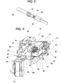
Fig. 2
eine Crimpverbindung, -
Fig. 3
einen Kontaktvorschub, -
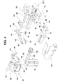
Fig. 4
Einzelheiten des Kontaktvorschubes, -
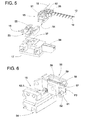
Fig. 5
Einzelheiten eines Unterwerkzeuges und -
Fig. 6
Einzelheiten eines Ambosswechselteils.
-
Fig. 1
a crimping press according to the invention, -
Fig. 2
a crimp connection, -
Fig. 3
a contact feed, -
Fig. 4
Details of the contact feed, -
Fig. 5
Details of a lower tool and -
Fig. 6
Details of an anvil change part.
Der Greifer 30 besteht im wesentlichen aus einer zweiten Druckplatte 64 und aus einer ersten Gegenplatte 65, wobei die zweite Druckplatte 64 mittels drittem nicht sichtbarem Aktuator 66 über nicht sichtbare Stössel betätigbar ist. Der zweiten Druckplatte 64 wird eine mittels erstem Handgriff 67 manuell wegschwenkbaren Anschlagplatte 68 entgegengehalten.The
Der Vorschub des Kontaktgurtes 12 erfolgt mittels Greifer 30, der den Kontaktgurt 12 zwischen der zweiten Druckplatte 64 und der ersten Gegenplatte 65 festklemmt und mit der Bewegung P1 des Vorschubmotors 14 vorschiebt währenddem die erste Druckplatte 58 betätigt bzw. in der unteren Lage ist bzw. die ersten Stifte 59 aus der Führungsbahn 57 entfernt sind. Nach dem Vorschub wird die erste Druckplatte 58 nach oben bewegt und die ersten Stifte 59 in die Transportlöcher 60 geschoben. Dann wird der Greifer 30 geöffnet bzw. die zweite Druckplatte 64 abgesenkt und der erste Schlitten 27 in Richtung P1 mittels Vorschubmotor 14 zurückgezogen. Dann wird der Greifer 30 erneut geschlossen und der Kontaktgurt 12 festgeklemmt. Vor dem Vorschieben des Kontaktgurtes 12 wird die erste Druckplatte 58 erneut nach unten bewegt und die Führungsbahn 57 von den ersten Stiften 59 befreit. Der Greifer 30 schiebt den Kontaktgurt 12 unabhängig vom Transportlochabstand und unabhängig von der Breite des Kontaktgurtes 12 softwaregesteuert um genau ein Kontaktraster bzw. um einen Transportlochabstand vor. Nach erfolgtem Vorschub werden die ersten Stifte 59 nach oben bewegt. Ein Sensor überwacht, ob die ersten Stifte 59 in die Transportlöcher 60 greifen und den Kontaktgurt 12 festhalten. Danach wird der Greifer 30 geöffnet und zurückgefahren.The feed of the
Claims (8)
- Crimping press for connecting belt-linked crimp contacts (19) to cables (18) by means of crimpers (8, 9) and an interchangeable anvil part (15), a contact advancing means (13) advancing a contact belt (12), which carries the crimp contacts (19), as far as the interchangeable anvil part (15), characterized in that the contact advancing means (13) has a gripper (30) which is independent of the transport hole spacing and of the width of the contact belt (12), holds the contact belt (12) firmly by means of pressure plates (64, 65) which form a frictional connection with the contact belt (12), and advances the said contact belt (12) as far as the interchangeable anvil part (15), a belt holder (56) being provided for firm holding and all-round positioning of the contact belt (12) on the interchangeable anvil part (15), which belt holder (56), just like the interchangeable anvil part (15), is designed specifically for the crimp contacts and fits as an interchangeable part for a contact-belt type, and which has controllable positioning elements (59) which are arranged for the all-round positioning of the contact belt (12) in the advancing direction and engage into transport holes (60) of the contact belt (12).
- Crimping press according to Claim 1, characterized in that the belt holder (56) is provided as a guide for the contact belt (12).
- Crimping press according to either of Claims 1 and 2, characterized in that the gripper (30) can be positioned in the transverse direction (P2) by means of the interchangeable anvil part (15).
- Crimping press according to one of Claims 1 to 3, characterized in that the gripper (30) is arranged movably on a first carriage (27) which can be moved in the advancing direction (P1), and can be adjusted in the transverse direction (P2) by means of a second carriage (32) which is arranged on the first carriage (27).
- Crimping press according to Claim 4, characterized in that the interchangeable anvil part (15) has a first stop (54) which, during insertion of the interchangeable anvil part (15), actuates a first pin (37) of the second carriage (32) and positions the gripper (30) on the contact belt (12) in the transverse direction (P2).
- Crimping press according to one of the preceding claims, characterized in that, in order to clamp the contact belt (12) firmly, the gripper (30) has a second pressure plate (64), which can be actuated by means of actuator (66), and a first mating plate (65).
- Crimping press according to one of the preceding claims, characterized in that the belt holder (56) of the interchangeable anvil part (15) has a guide track (57) for the contact belt (12) and a first actuable pressure plate (58) with first pins (59), the first pins (59) fitting into the transport holes of the contact belt (12).
- Crimping press according to Claim 7, characterized in that the first pressure plate (58) can be actuated by means of a first rotatable lever (43), a lever fork (47) moving a fourth pin (61) of the first pressure plate (58) in the actuating direction (P3) and lifting the first pins (59) into the guide track (57) or out of the guide track (57).
Priority Applications (1)
| Application Number | Priority Date | Filing Date | Title |
|---|---|---|---|
| EP20060120624 EP1764884B1 (en) | 2005-09-19 | 2006-09-14 | Crimping press |
Applications Claiming Priority (2)
| Application Number | Priority Date | Filing Date | Title |
|---|---|---|---|
| EP05108631 | 2005-09-19 | ||
| EP20060120624 EP1764884B1 (en) | 2005-09-19 | 2006-09-14 | Crimping press |
Publications (2)
| Publication Number | Publication Date |
|---|---|
| EP1764884A1 EP1764884A1 (en) | 2007-03-21 |
| EP1764884B1 true EP1764884B1 (en) | 2013-04-03 |
Family
ID=37733884
Family Applications (1)
| Application Number | Title | Priority Date | Filing Date |
|---|---|---|---|
| EP20060120624 Active EP1764884B1 (en) | 2005-09-19 | 2006-09-14 | Crimping press |
Country Status (1)
| Country | Link |
|---|---|
| EP (1) | EP1764884B1 (en) |
Families Citing this family (5)
| Publication number | Priority date | Publication date | Assignee | Title |
|---|---|---|---|---|
| RS60591B1 (en) | 2013-04-24 | 2020-08-31 | Komax Holding Ag | Cable conversion device for cutting, stripping and converting a cable with crimp contacts |
| EP3240123B1 (en) | 2016-04-27 | 2019-06-26 | Komax Holding AG | Crimp tool exchange device and method for exchanging first crimping tool fixed in a process position arranged in a crimping press for another second crimping tool |
| CN106493535B (en) * | 2016-11-30 | 2018-07-24 | 芜湖航天特种电缆厂股份有限公司 | The flower tooth shaft feeding device of grass trimmer head section kludge |
| US11128095B2 (en) | 2017-04-25 | 2021-09-21 | Komax Holding Ag | Method for aligning a crimper of a first tool of a crimping press relative to an anvil of a second tool of the crimping press and a crimping press device |
| RS64173B1 (en) | 2017-04-25 | 2023-05-31 | Komax Holding Ag | Method for aligning a crimper of a first tool of a crimping press relative to an anvil of a second tool of the crimping press and a crimping press device |
Family Cites Families (4)
| Publication number | Priority date | Publication date | Assignee | Title |
|---|---|---|---|---|
| US4025999A (en) | 1976-02-18 | 1977-05-31 | Joseph Wolyn | Adjustable crimp die assembly |
| DE59803090D1 (en) | 1997-11-07 | 2002-03-21 | Wolfgang Hanke | CRIMP TOOL |
| FR2782578B1 (en) * | 1998-08-21 | 2002-03-15 | Sierma Ingenierie Sa | DEVICE FOR SERIES CRIMPING OF METAL TERMINALS AND PRESET CASSETTE FOR GUIDING A TERMINAL STRIP |
| MXPA01003356A (en) | 2000-04-10 | 2004-07-30 | Sumitomo Wiring Systems | Terminal crimping device. |
-
2006
- 2006-09-14 EP EP20060120624 patent/EP1764884B1/en active Active
Also Published As
| Publication number | Publication date |
|---|---|
| EP1764884A1 (en) | 2007-03-21 |
Similar Documents
| Publication | Publication Date | Title |
|---|---|---|
| EP0889561B1 (en) | Crimp press and method for use | |
| DE60103588T2 (en) | Device for pressing cable end clamps | |
| DE69828723T2 (en) | Motion control mechanism for attaching connectors | |
| EP1764884B1 (en) | Crimping press | |
| DE4110121C2 (en) | Method for mounting an electrical connection in a work station provided with a stop and device for carrying out the method | |
| DE2808518C2 (en) | Machine for attaching contact elements to electrical wire conductors | |
| DE2024821B2 (en) | Device for connecting electrical connection parts to the flat conductors of an insulated flat ribbon cable | |
| EP2631031B1 (en) | Transfer device for pushing press in elements to a sheet processing tool and sheet processing tool with such a transfer device | |
| EP1351349B1 (en) | Crimping press for making crimp connections | |
| EP1341269B1 (en) | Crimping press for making crimp connections | |
| DE4102425C2 (en) | Cable manufacturing device | |
| DE202009001625U1 (en) | Separating device for shearing of strung on a supply tape workpieces | |
| DE3223086C2 (en) | ||
| DE4102449C2 (en) | Harness making machine | |
| EP0363765A2 (en) | Process and device for carrying out of double crimping on electrical connectors | |
| EP1381124B1 (en) | Crimping press with contact feeding | |
| EP1381123B1 (en) | Crimping press having a feeding device | |
| DE1615052B2 (en) | METHOD AND MACHINE FOR PRODUCING WIRE CONNECTIONS | |
| US7757386B2 (en) | Crimping press | |
| CH689288A5 (en) | Method and apparatus for loading Steckergehaeusen. | |
| EP0889560B1 (en) | Method and unit for feeding contacts to a contact processing apparatus | |
| DE3540083C2 (en) | ||
| EP0994539B1 (en) | Device for assembling a cable | |
| DE102008007183B4 (en) | Tool for the production of insulation displacement and / or crimp connections | |
| DE602005000633T2 (en) | Mounting device for the bearing mat of a ceramic catalyst carrier |
Legal Events
| Date | Code | Title | Description |
|---|---|---|---|
| PUAI | Public reference made under article 153(3) epc to a published international application that has entered the european phase |
Free format text: ORIGINAL CODE: 0009012 |
|
| AK | Designated contracting states |
Kind code of ref document: A1 Designated state(s): AT BE BG CH CY CZ DE DK EE ES FI FR GB GR HU IE IS IT LI LT LU LV MC NL PL PT RO SE SI SK TR |
|
| AX | Request for extension of the european patent |
Extension state: AL BA HR MK YU |
|
| 17P | Request for examination filed |
Effective date: 20070910 |
|
| 17Q | First examination report despatched |
Effective date: 20071025 |
|
| AKX | Designation fees paid |
Designated state(s): CH DE FR GB IT LI |
|
| GRAP | Despatch of communication of intention to grant a patent |
Free format text: ORIGINAL CODE: EPIDOSNIGR1 |
|
| GRAS | Grant fee paid |
Free format text: ORIGINAL CODE: EPIDOSNIGR3 |
|
| GRAA | (expected) grant |
Free format text: ORIGINAL CODE: 0009210 |
|
| AK | Designated contracting states |
Kind code of ref document: B1 Designated state(s): CH DE FR GB IT LI |
|
| REG | Reference to a national code |
Ref country code: GB Ref legal event code: FG4D Free format text: NOT ENGLISH |
|
| REG | Reference to a national code |
Ref country code: CH Ref legal event code: EP |
|
| REG | Reference to a national code |
Ref country code: DE Ref legal event code: R096 Ref document number: 502006012673 Country of ref document: DE Effective date: 20130529 |
|
| PLBE | No opposition filed within time limit |
Free format text: ORIGINAL CODE: 0009261 |
|
| STAA | Information on the status of an ep patent application or granted ep patent |
Free format text: STATUS: NO OPPOSITION FILED WITHIN TIME LIMIT |
|
| 26N | No opposition filed |
Effective date: 20140106 |
|
| REG | Reference to a national code |
Ref country code: DE Ref legal event code: R097 Ref document number: 502006012673 Country of ref document: DE Effective date: 20140106 |
|
| GBPC | Gb: european patent ceased through non-payment of renewal fee |
Effective date: 20130914 |
|
| PG25 | Lapsed in a contracting state [announced via postgrant information from national office to epo] |
Ref country code: GB Free format text: LAPSE BECAUSE OF NON-PAYMENT OF DUE FEES Effective date: 20130914 |
|
| REG | Reference to a national code |
Ref country code: CH Ref legal event code: NV Representative=s name: INVENTIO AG, CH |
|
| REG | Reference to a national code |
Ref country code: FR Ref legal event code: PLFP Year of fee payment: 11 |
|
| REG | Reference to a national code |
Ref country code: FR Ref legal event code: PLFP Year of fee payment: 12 |
|
| REG | Reference to a national code |
Ref country code: FR Ref legal event code: PLFP Year of fee payment: 13 |
|
| PGFP | Annual fee paid to national office [announced via postgrant information from national office to epo] |
Ref country code: FR Payment date: 20190926 Year of fee payment: 14 |
|
| PG25 | Lapsed in a contracting state [announced via postgrant information from national office to epo] |
Ref country code: FR Free format text: LAPSE BECAUSE OF NON-PAYMENT OF DUE FEES Effective date: 20200930 |
|
| PGFP | Annual fee paid to national office [announced via postgrant information from national office to epo] |
Ref country code: IT Payment date: 20230920 Year of fee payment: 18 |
|
| PGFP | Annual fee paid to national office [announced via postgrant information from national office to epo] |
Ref country code: DE Payment date: 20230928 Year of fee payment: 18 |
|
| PGFP | Annual fee paid to national office [announced via postgrant information from national office to epo] |
Ref country code: CH Payment date: 20231001 Year of fee payment: 18 |