EP1764738A1 - Systeme de traitement du signal et programme de traitement du signal - Google Patents
Systeme de traitement du signal et programme de traitement du signal Download PDFInfo
- Publication number
- EP1764738A1 EP1764738A1 EP05757820A EP05757820A EP1764738A1 EP 1764738 A1 EP1764738 A1 EP 1764738A1 EP 05757820 A EP05757820 A EP 05757820A EP 05757820 A EP05757820 A EP 05757820A EP 1764738 A1 EP1764738 A1 EP 1764738A1
- Authority
- EP
- European Patent Office
- Prior art keywords
- noise
- signals
- luminance
- target region
- processing
- Prior art date
- Legal status (The legal status is an assumption and is not a legal conclusion. Google has not performed a legal analysis and makes no representation as to the accuracy of the status listed.)
- Withdrawn
Links
- 238000012545 processing Methods 0.000 title claims abstract description 262
- 230000009467 reduction Effects 0.000 claims abstract description 107
- 238000009499 grossing Methods 0.000 claims description 51
- 238000012937 correction Methods 0.000 claims description 50
- 238000004364 calculation method Methods 0.000 claims description 17
- 230000008030 elimination Effects 0.000 claims description 13
- 238000003379 elimination reaction Methods 0.000 claims description 13
- 230000035945 sensitivity Effects 0.000 claims description 10
- 238000000605 extraction Methods 0.000 claims description 4
- 230000000295 complement effect Effects 0.000 claims description 3
- 238000000926 separation method Methods 0.000 claims description 3
- 238000010586 diagram Methods 0.000 description 44
- 230000000875 corresponding effect Effects 0.000 description 35
- 238000012546 transfer Methods 0.000 description 23
- 230000003595 spectral effect Effects 0.000 description 13
- 238000006243 chemical reaction Methods 0.000 description 12
- 238000000034 method Methods 0.000 description 7
- 230000006870 function Effects 0.000 description 6
- 238000004458 analytical method Methods 0.000 description 5
- 230000008859 change Effects 0.000 description 4
- 230000006835 compression Effects 0.000 description 4
- 238000007906 compression Methods 0.000 description 4
- 230000000694 effects Effects 0.000 description 4
- 239000000284 extract Substances 0.000 description 4
- 230000003321 amplification Effects 0.000 description 3
- 238000001914 filtration Methods 0.000 description 3
- 238000003199 nucleic acid amplification method Methods 0.000 description 3
- 238000004321 preservation Methods 0.000 description 3
- 238000010276 construction Methods 0.000 description 2
- 230000001276 controlling effect Effects 0.000 description 2
- 230000002596 correlated effect Effects 0.000 description 2
- 230000002708 enhancing effect Effects 0.000 description 2
- 238000011156 evaluation Methods 0.000 description 2
- 238000005375 photometry Methods 0.000 description 2
- 230000008569 process Effects 0.000 description 2
- 238000005070 sampling Methods 0.000 description 2
- 230000003044 adaptive effect Effects 0.000 description 1
- 230000002950 deficient Effects 0.000 description 1
- 230000006866 deterioration Effects 0.000 description 1
- 238000004134 energy conservation Methods 0.000 description 1
- 238000001228 spectrum Methods 0.000 description 1
- 238000012795 verification Methods 0.000 description 1
Images


Classifications
-
- H—ELECTRICITY
- H04—ELECTRIC COMMUNICATION TECHNIQUE
- H04N—PICTORIAL COMMUNICATION, e.g. TELEVISION
- H04N9/00—Details of colour television systems
- H04N9/64—Circuits for processing colour signals
- H04N9/646—Circuits for processing colour signals for image enhancement, e.g. vertical detail restoration, cross-colour elimination, contour correction, chrominance trapping filters
-
- G—PHYSICS
- G06—COMPUTING; CALCULATING OR COUNTING
- G06T—IMAGE DATA PROCESSING OR GENERATION, IN GENERAL
- G06T5/00—Image enhancement or restoration
- G06T5/20—Image enhancement or restoration by the use of local operators
-
- G06T5/70—
-
- H—ELECTRICITY
- H04—ELECTRIC COMMUNICATION TECHNIQUE
- H04N—PICTORIAL COMMUNICATION, e.g. TELEVISION
- H04N23/00—Cameras or camera modules comprising electronic image sensors; Control thereof
- H04N23/80—Camera processing pipelines; Components thereof
- H04N23/84—Camera processing pipelines; Components thereof for processing colour signals
-
- H—ELECTRICITY
- H04—ELECTRIC COMMUNICATION TECHNIQUE
- H04N—PICTORIAL COMMUNICATION, e.g. TELEVISION
- H04N25/00—Circuitry of solid-state image sensors [SSIS]; Control thereof
- H04N25/10—Circuitry of solid-state image sensors [SSIS]; Control thereof for transforming different wavelengths into image signals
- H04N25/11—Arrangement of colour filter arrays [CFA]; Filter mosaics
- H04N25/13—Arrangement of colour filter arrays [CFA]; Filter mosaics characterised by the spectral characteristics of the filter elements
- H04N25/134—Arrangement of colour filter arrays [CFA]; Filter mosaics characterised by the spectral characteristics of the filter elements based on three different wavelength filter elements
-
- H—ELECTRICITY
- H04—ELECTRIC COMMUNICATION TECHNIQUE
- H04N—PICTORIAL COMMUNICATION, e.g. TELEVISION
- H04N25/00—Circuitry of solid-state image sensors [SSIS]; Control thereof
- H04N25/60—Noise processing, e.g. detecting, correcting, reducing or removing noise
-
- G—PHYSICS
- G06—COMPUTING; CALCULATING OR COUNTING
- G06T—IMAGE DATA PROCESSING OR GENERATION, IN GENERAL
- G06T2207/00—Indexing scheme for image analysis or image enhancement
- G06T2207/10—Image acquisition modality
- G06T2207/10024—Color image
-
- H—ELECTRICITY
- H04—ELECTRIC COMMUNICATION TECHNIQUE
- H04N—PICTORIAL COMMUNICATION, e.g. TELEVISION
- H04N25/00—Circuitry of solid-state image sensors [SSIS]; Control thereof
- H04N25/10—Circuitry of solid-state image sensors [SSIS]; Control thereof for transforming different wavelengths into image signals
- H04N25/11—Arrangement of colour filter arrays [CFA]; Filter mosaics
- H04N25/13—Arrangement of colour filter arrays [CFA]; Filter mosaics characterised by the spectral characteristics of the filter elements
- H04N25/135—Arrangement of colour filter arrays [CFA]; Filter mosaics characterised by the spectral characteristics of the filter elements based on four or more different wavelength filter elements
- H04N25/136—Arrangement of colour filter arrays [CFA]; Filter mosaics characterised by the spectral characteristics of the filter elements based on four or more different wavelength filter elements using complementary colours
Definitions
- the present invention relates to processing for random noise reduction in color signals and luminance signals due to an image pickup device system, and further relates to a signal processing system and a signal processing program which reduce only noise components with high precision by dynamically estimating the amount of noise generated, without any influence of shooting conditions.
- Noise components included in digitized signals obtained from an image pickup device and an analog circuit and an A/D converter associated with the image pickup device can be generally classified in to fixed pattern noise and random noise.
- the fixed pattern noise is noise that originates primarily in the image pickup device, and is typified by defective pixels or the like.
- random noise is generated in the image pickup device and analog circuit, and has characteristics close to white noise properties.
- Japanese Unexamined Patent Application Publication No. 2001-157057 discloses a technique wherein the amount of luminance noise is converted into a function as to the signal level, the amount of luminance noise as to the signal level is estimated from this function, and the filtering frequency properties are controlled based on the amount of luminance noise.
- appropriate noise reduction processing can be performed on the signal level.
- Japanese Unexamined Patent Application Publication No. 2001-175843 discloses a technique wherein input signals are divided into luminance and color difference signals, edge intensity is obtained from the luminance signals and color difference signals, and smoothing processing of color difference signals is performed at regions other than the edge portion. Thus, color noise reduction processing is performed at smooth portions.
- N ad cD
- N the amount of luminance noise
- D the signal level converted in to density value.
- a, b, and c are constant terms, allocated statically.
- the amount of luminance noise changes dynamically according to factors such as the temperature, exposure time and gain for each shooting operation and so forth. Accordingly, there is the problem that formulization cannot be carried out handling the amount of noise at each shooting operation, so the estimation precision of the amount of noise deteriorates.
- filtering frequency properties are controlled from the amount of noise, but this filtering is performed equally on both smooth portions and edge portions, with no discernment therebetween.
- edge portions which are at regions which have been estimated to have a great amount of noise based on the signal level, deteriorate. That is to say, this processing cannot handle discerning between original signals and noise, so there is the problem that preservation of original signals is poor. Moreover, there is the problem that color noise occurring between the color signals cannot be handled.
- the present invention has been made in light of the above-described problems, and accordingly it is an object thereof to provide a signal processing system and a signal processing program wherein modeling is performed for the amount of noise of color signals and luminance signals corresponding to not only signal level but also to factors which dynamically change, such as temperature at each shooting operation, gain, and so forth, thereby enabling noise reduction processing optimized for shooting conditions. It is also an object thereof to provide a signal processing system and a signal processing program wherein noise reduction processing is independently performed on both luminance noise and color noise, thereby realizing high-precision reduction of both noises, and generating high-quality signals.
- a signal processing system for performing noise reduction processing on signals from an image pickup device in front of which is arranged a color filter, comprises: extracting means for extracting a local region, from the signals, formed by a target region which noise reduction processing is performed, and at least one or more nearby regions which exist neighborhood of the target region; separating means for calculating luminance signals and color difference signals for each of the target region and the nearby regions; selecting means for selecting the nearby regions similar to the target region; noise estimating means for estimating the amount of noise from the target region and the nearby region selected by the selecting means; and noise reduction means for reducing noise in the target region based on the amount of noise.
- Embodiments corresponding to this invention are Embodiment 1 shown in Fig. 1 through Fig. 9, and Embodiment 2 shown in Fig. 10 through Fig. 15.
- An extracting unit 112 shown in Fig. 1, Fig. 8, and Fig. 10 corresponds to the extracting means
- a Y/C separating unit 113 shown in Fig. 1, Fig. 8, and Fig. 10 corresponds to the separating means
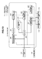
- a selecting unit 114 shown in Fig. 1, Fig. 3, Fig. 8, Fig. 10, Fig. 12, and Fig. 13 corresponds to the selecting means
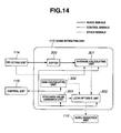
- a noise estimating unit 115 shown in Fig. 1, Fig. 5, Fig. 8, Fig. 10, and Fig. 14 corresponds to the noise estimating means
- a noise reduction unit 116 shown in Fig. 1, Fig. 7, Fig. 8, and Fig. 10 corresponds to the noise reduction means.
- a preferable application of this invention is a signal processing system wherein a local region formed by a target region which noise reduction processing is performed, and at least one or more nearby regions which exist neighborhood of the target region, are extracted by the extracting unit 112; signals are separated into luminance signals and color difference signals by the Y/C separating unit 113; nearby regions similar to the target region are selected by the selecting unit 114; the amount of noise from the target region and the selected nearby region is estimated by the noise estimating unit 115; and noise is reduced in the target region by the noise reduction unit 116.
- a nearby region similar to the target region regarding which noise reduction processing is to be performed is selected, the amount of noise is estimated for each of the target region and the nearby region, and noise reduction processing is performed according to the estimated noise amount, so high-precision noise amount estimation and optimal noise reduction can be made throughout the entire image, thereby yielding high-precision signals.
- the image pickup device is a single image sensor in front of which is arranged a Bayer (hereafter written as "Bayer") type primary color filter constituted of R (red), G (green), and B (blue), or a single image sensor in front of which is arranged a color difference line sequential type complementary color filter constituted of Cy (cyan), Mg (magenta), Ye (yellow), and G (green).
- Bayer hereafter written as "Bayer” type primary color filter constituted of R (red), G (green), and B (blue)
- Embodiments corresponding to this invention are Embodiment 1 shown in Fig. 1 through Fig. 9, and Embodiment 2 shown in Fig. 10 through Fig. 15.
- a preferable application example of this invention is a signal processing system wherein a Bayer type primary color filter shown in Fig. 2A or a color difference line sequential type complementary color filter shown in Fig. 11A is arranged in front of an image pickup device.
- noise reduction processing is performed according to a Bayer or color difference line sequential type color filter placement, so high-speed processing can be realized.
- the target region and nearby regions are regions including at least one set or more color filters necessary for calculating the luminance signals and the color difference signals.
- Embodiments corresponding to this invention are Embodiment 1 shown in Fig. 1 through Fig. 9, and Embodiment 2 shown in Fig. 10 through Fig. 15.
- a preferable application example of this invention is a signal processing system using the target region and nearby regions shown in Fig. 2A, Fig. 2C, Fig. 2D, and Fig. 11A.
- luminance signals and color difference signals can be calculated at each of the target region where noise reduction processing is performed and nearby regions where the amount of noise is estimated, so estimation of noise amount can be made using a larger area, and the precision of estimation can be improved.
- the selecting means comprise: hue calculating means for calculating hue signals for each of the target region and the nearby regions; similarity determining means for determining a similarity of the target region and the nearby regions based on at least one of the luminance signals and the hue signals; and nearby region selecting means for selecting the nearby regions based on the similarity.
- Embodiments corresponding to this invention are Embodiment 1 shown in Fig. 1 through Fig. 9, and Embodiment 2 shown in Fig. 10 through Fig. 15.
- a hue calculating unit 203 shown in Fig. 3, Fig. 12, and Fig. 13 corresponds to the hue calculating means
- a similarity determining unit 206 shown in Fig. 3, Fig. 12, and Fig. 13 corresponds to the similarity determining means
- a nearby region selecting unit 207 shown in Fig. 3, Fig. 12, and Fig. 13 corresponds to the nearby region selecting means.
- a preferable application example of this invention is a signal processing system wherein hue signals are calculated for each of the target region and the nearby regions by the hue calculating unit 203; the similarity of the target region and the nearby regions is determined by the similarity determining unit 206 based on at least one of the luminance signals and the hue signals; and nearby regions similar to the target region are selected by the nearby region selecting unit 207.
- nearby regions similar to the target region are extracted based on at least one of the luminance signals and hue signals, so noise amount estimation can be made from uniform regions, and estimation precision improves. Also, calculation of the luminance signals and hue signals is easy, so a high-speed and low-cost system can be provided.
- the selecting means comprise: hue calculating means for calculating hue signals for each of the target region and the nearby regions; edge calculating means for calculating edge signals for each of the target region and the nearby regions; similarity determining means for determining the similarity of the target region and the nearby regions based on at least one of the luminance signals and the hue signals and the edge signals; and nearby region selecting means for selecting the nearby regions based on the similarity.
- Embodiment 2 shown in Fig. 10 through Fig. 15.
- the hue calculating unit 203 shown in Fig. 12 corresponds to the hue calculating means
- an edge calculating unit 600 shown in Fig. 12 corresponds to the edge calculating means
- the similarity determining unit 206 shown in Fig. 12 corresponds to the similarity determining means
- the nearby region selecting unit 207 shown in Fig. 12 corresponds to the nearby region selecting means.
- a preferable application example of this invention is a signal processing system wherein hue signals are calculated for each of the target region and the nearby regions by the hue calculating unit 203; edge signals are calculated at the edge calculating unit 600; the similarity of the target region and the nearby regions is determined by the similarity determining unit 206 based on at least one of the luminance signals and the hue signals and the edge signals; and nearby regions similar to the target region are selected by the nearby region selecting unit 207.
- nearby regions similar to the target region are extracted based on at least one of the luminance signals and hue signals and edge signals, so noise amount estimation can be made from uniform regions, and estimation precision improves. Also, calculation of the luminance signals and hue signals and edge signals is easy, so a high-speed and low-cost system can be provided.
- the selecting means comprise: hue calculating means for calculating hue signals for each of the target region and the nearby regions; frequency calculating means for calculating frequency signals for each of the target region and the nearby regions; similarity determining means for determining the similarity of the target region and the nearby regions based on at least one of the luminance signals and the hue signals and the frequency signals; and nearby region selecting means for selecting the nearby regions based on the similarity.
- Embodiment 2 shown in Fig. 10 through Fig. 15.
- the hue calculating unit 203 shown in Fig. 13 corresponds to the hue calculating means
- a DCT conversion unit 700 shown in Fig. 13 corresponds to the frequency calculating means
- the similarity determining unit 206 shown in Fig. 13 corresponds to the similarity determining means
- the nearby region selecting unit 207 shown in Fig. 13 corresponds to the nearby region selecting means.
- a preferable application example of this invention is a signal processing system wherein hue signals are calculated for each of the target region and the nearby regions by the hue calculating unit 203; frequency signals are calculated at the DCT conversion unit 700; the similarity of the target region and the nearby regions is determined by the similarity determining unit 206 based on at least one of the luminance signals and the hue signals and the frequency signals; and nearby regions similar to the target region are selected by the nearby region selecting unit 207.
- nearby regions similar to the target region are extracted based on at least one of the luminance signals and hue signals and frequency signals, so noise amount estimation can be made from uniform regions, and estimation precision improves. Also, selection based on frequency signals enables verification of similarity to be performed with higher precision.
- the selecting means comprise control means for controlling such that the nearby regions used by the noise estimating means and the noise reduction means differ.
- Embodiments corresponding to this invention are Embodiment 1 shown in Fig. 1 through Fig. 9, and Embodiment 2 shown in Fig. 10 through Fig. 15.
- a control unit 119 shown in Fig. 1, Fig. 8, and Fig. 10 corresponds to the control means.
- a preferable application example of this invention is a signal processing system wherein the control unit 119 controls such that the nearby regions used by the noise estimating unit 115 and the noise reduction unit 116 differ, with regard to the target region and nearby regions obtained by the extracting unit 112 and the selecting unit 114.
- control is effected such that a few nearby regions are used with the noise estimating means and many nearby regions are used with the noise reduction means, so the precision of noise estimation processing is raised by performing estimation from a narrow region, and the effectiveness of noise reduction processing is improved by reducing from a wide region.
- Region sizes can be set adaptive for each processing, so signals with higher quality can be obtained.
- the selecting means comprise elimination means for eliminating predetermined minute fluctuations from the signals of the target region and the nearby regions.
- Embodiments corresponding to this invention are Embodiment 1 shown in Fig. 1 through Fig. 9, and Embodiment 2 shown in Fig. 10 through Fig. 15.
- a minute fluctuation elimination unit 200 shown in Fig. 3, Fig. 12, and Fig. 13 corresponds to the elimination means.
- a preferable application example of this invention is a signal processing system wherein minute fluctuations are eliminated from the signals of the target region and the nearby regions by the minute fluctuation elimination unit 200.
- hue signals are obtained following eliminating minute fluctuations from the signals, so the stability of hue signals improves, and nearby regions can be extracted with higher precision.
- the selecting means comprises coefficient calculating means for calculating weighting coefficients for the nearby regions based on the similarity.
- Embodiments corresponding to this invention are Embodiment 1 shown in Fig. 1 through Fig. 9, and Embodiment 2 shown in Fig. 10 through Fig. 15.
- a coefficient calculating unit 208 shown in Fig. 3, Fig. 12, and Fig. 13 corresponds to the coefficient calculating means.
- a preferable application example of this invention is a signal processing system wherein weighting coefficients are calculated by the coefficient calculating unit 208, based on the similarity of the target region and the nearby regions.
- weighting coefficients are calculated based on the similarity of the nearby regions, so similarity with the target region can be employed in multiple stages, and high-precision noise estimation can be performed.
- the noise estimating means comprises at least one of color noise estimating means for estimating the amount of color noise from the target region and the nearby regions selected by the selecting means, and luminance noise estimating means for estimating the amount of luminance noise from the target region and the nearby regions selected by the selecting means.
- Embodiments corresponding to this invention are Embodiment 1 shown in Fig. 1 through Fig. 9, and Embodiment 2 shown in Fig. 10 through Fig. 15.
- a noise estimating unit 115 shown in Fig. 1, Fig. 5, Fig. 8, Fig. 10 and Fig. 14 corresponds to the color noise estimating means
- the noise estimating unit 115 shown in Fig. 1, Fig. 5, Fig. 8, Fig. 10 and Fig. 14 corresponds to the luminance noise estimating means.
- a preferable application example of this invention is a signal processing system wherein at least one of the amount of color noise and the amount of luminance noise is estimated by the noise estimating unit 115.
- the color noise amount and the luminance noise amount can be independently estimated, whereby the estimation of each can be improved.
- the color noise estimating means comprises: collecting means for collecting information relating to temperature values of the image pickup device and gain value corresponding to the signals; assigning means for assigning standard values for information which cannot be obtained by the collecting means; average color difference calculating means for calculating average color difference values from the target region and the nearby regions selected by the selecting means; and color noise amount calculating means for calculating the amount of color noise, based on the information from the collecting means or assigning means, and the average color difference values.
- Embodiments corresponding to this invention are Embodiment 1 shown in Fig. 1 through Fig. 9, and Embodiment 2 shown in Fig. 10 through Fig. 15.
- a temperature sensor 121 and control unit 119 shown in Fig. 1 and Fig. 10, and a gain calculating unit 302 shown in Fig. 5 and Fig. 14, correspond to the collecting means
- a standard value assigning unit 303 shown in Fig. 5 and Fig. 14 corresponds to the assigning means
- an average calculating unit 301 shown in Fig. 5 and Fig. 14 corresponds to the average color difference calculating means
- a parameter ROM 304, parameter selecting unit 305, interpolation unit 306, correcting unit 307, shown in Fig. 5, and a look-up table unit 800 shown in Fig. 14, correspond to the color noise amount calculating means.
- a preferable application example of this invention is a signal processing system wherein information used for noise amount estimation is collected with the temperature sensor 121, control unit 119, and gain calculating unit 302, a standard value is set by the standard value assigning unit 303 in the case that information from the temperature sensor 121, control unit 119, and gain calculating unit 302 cannot be obtained, an average color different value is calculated by the average calculating unit 301 from the target region and nearby regions, and the amount of noise is obtained by the parameter ROM 304, parameter selecting unit 305, interpolation unit 306, correcting unit 307, or the look-up table unit 800.
- various types of information relating to the amount of noise is dynamically obtained for each shooting operation, and a standard value is set for information which is not obtained, and color noise amount is calculated from this information, so high-precision color noise amount estimation can be performed while dynamically adapting to different conditions for each shooting operation. Also, the amount of color noise can be estimated even in the case that necessary information cannot be obtained, thereby stable noise reduction effects are obtained.
- the luminance noise estimating means comprises: collecting means for collecting information relating to temperature values of the image pickup device and gain value corresponding to the signals; assigning means for assigning standard values for information which cannot be obtained by the collecting means; average luminance calculating means for calculating average luminance values from the target region and the nearby regions selected by the selecting means; and luminance noise amount calculating means for calculating the amount of luminance noise, based on the information from the collecting means or assigning means, and the average luminance values.
- Embodiments corresponding to this invention are Embodiment 1 shown in Fig. 1 through Fig. 9, and Embodiment 2 shown in Fig. 10 through Fig. 15.
- the temperature sensor 121 and control unit 119 shown in Fig. 1 and Fig. 10, and the gain calculating unit 302 shown in Fig. 5 and Fig. 14, correspond to the collecting means
- the standard value assigning unit 303 shown in Fig. 5 and Fig. 14 corresponds to the assigning means
- the average calculating unit 301 shown in Fig. 5 and Fig. 14 corresponds to the average luminance calculating means
- the parameter ROM 304, parameter selecting unit 305, interpolation unit 306, correcting unit 307, shown in Fig. 5, and the look-up table unit 800 shown in Fig. 14, correspond to the luminance noise amount calculating means.
- a preferable application example of this invention is a signal processing system wherein information used for noise amount estimation is collected with the temperature sensor 121, control unit 119, and gain calculating unit 302, a standard value is set by the standard value assigning unit 303 in the case that information from the temperature sensor 121, control unit 119, and gain calculating unit 302 cannot be obtained, an average luminance value is calculated by the average calculating unit 301 from the target region and nearby regions, and the amount of luminance noise is obtained by the parameter ROM 304, parameter selecting unit 305, interpolation unit 306, correcting unit 307, or the look-up table unit 800.
- various types of information relating to the amount of noise is dynamically obtained for each shooting operation, and a standard value is applied for information which is not obtained, and luminance noise amount is calculated from this information, so high-precision luminance noise amount estimation can be performed while dynamically adapting to different conditions for each shooting operation. Also, the amount of luminance noise can be estimated even in the case that necessary information cannot be obtained, thereby stable noise reduction effects are obtained.
- the collecting means comprise a temperature sensor for measuring the temperature value of the image pickup device.
- Embodiments corresponding to this invention are Embodiment 1 shown in Fig. 1 through Fig. 9, and Embodiment 2 shown in Fig. 10 through Fig. 15.
- the temperature sensor 121 shown in Fig. 1 and Fig. 10 corresponds to the temperature sensor.
- a preferable application example of this invention is a signal processing system wherein the temperature of the CCD 103 is measured in real-time by the temperature sensor 121.
- the temperature of the image pickup device at each shooting operation is measured, and used as information for noise amount estimation, thereby enabling high-precision noise amount estimation to be performed while dynamically adapting to temperature change at each shooting operation.
- the collecting means comprise gain calculating means for obtaining the gain value, based on at least one or more information of ISO sensitivity, exposure information, and white balance information.
- Embodiments corresponding to this invention are Embodiment 1 shown in Fig. 1 through Fig. 9, and Embodiment 2 shown in Fig. 10 through Fig. 15.
- the gain calculating unit 302 and the control unit 119 shown in Fig. 5 and Fig. 14 correspond to the gain calculating means.
- a preferable application example of this invention is a signal processing system wherein ISO sensitivity, exposure information, white balance information, and so forth, is transferred at the control unit 119, and the total gain amount at each shooting operation is obtained by the gain calculating unit 302.
- the gain value at each shooting operation is obtained based on ISO sensitivity, exposure information, and white balance information, and this is taken as information for estimating the amount of noise, thereby enabling high-precision noise amount estimation to be performed while dynamically adapting to gain change at each shooting operation.
- the color noise amount calculating means comprise: recording means for recording at least one set or more of parameter groups constructed of a reference color noise model corresponding to a predetermined hue and a correction coefficient; parameter selecting means for selecting a necessary parameter from the parameter group, based on information from the collecting means or the assigning means, and the average color difference value; interpolation means for obtaining reference color noise amount by interpolation computation based on the average color difference value and a reference color noise model from a parameter group selected by the parameter selecting means; and correcting means for obtaining the color noise amount by correcting the reference color noise amount based on a correction coefficient from the parameter group selected by the parameter selecting means.
- Embodiment 1 shown in Fig. 1 through Fig. 9.
- the parameter ROM 304 shown in Fig. 5 corresponds to the recording means
- the parameter selecting unit 305 shown in Fig. 5 corresponds to the parameter selecting means
- the interpolation unit 306 shown in Fig. 5 corresponds to the interpolation means
- the correcting unit 307 shown in Fig. 5 corresponds to the correcting means.
- a preferable application example of this invention is a signal processing system wherein a coefficient and a correction coefficient of a reference color noise model, used for noise amount estimation, measured beforehand, are recorded in the parameter ROM 304; the coefficient and correction coefficient of the reference color noise model are selected by the parameter selecting unit 305, the reference color noise amount is calculated by the interpolation unit 306 by interpolation processing based on the reference color noise model; and the color noise amount is obtained by the correcting unit 307 by correcting the reference color noise amount based on the correction coefficient.
- the amount of color noise is obtained by interpolation and correction processing being performed based on the reference color noise model, so high-precision noise amount estimation is enabled. Also, implementation of interpolation and correction processing is easy, and a low-cost system can be provided.
- the reference color noise model is configured of a plurality of coordinate point data constructed of color noise amount as to color difference value.
- Embodiment 1 shown in Fig. 1 through Fig. 9.
- a preferable application example of this invention is a signal processing system using a reference color noise model configured of a plurality of coordinate point data shown in Fig. 6B.
- the reference color noise model is configured of a plurality of coordinate point data, so the amount of memory necessary for the model is small, enabling reduction in costs.
- the color noise amount calculating means comprise: look-up table means for obtaining color noise amount by inputting the information from the collecting means or the assigning means, and the average color difference value.
- Embodiment 2 shown in Fig. 10 through Fig. 15.
- the look-up table unit 800 shown in Fig. 14 corresponds to the look-up table means.
- a preferable application example of this invention is a signal processing system wherein the amount of color noise is obtained by the look-up table unit 800.
- color noise amount is calculated from a look-up table, enabling high-speed processing.
- the luminance noise amount calculating means comprise: recording means for recording a parameter group constructed of a reference luminance noise model and a correction coefficient; parameter selecting means for selecting a necessary parameter from the parameter group, based on information from the collecting means or the assigning means, and the average luminance value; interpolation means for obtaining reference luminance noise amount by interpolation computation based on the average luminance value and a reference luminance noise model from a parameter group selected by the parameter selecting means; and correcting means for obtaining the luminance noise amount by correcting the reference luminance noise amount based on a correction coefficient from the parameter group selected by the parameter selecting means.
- Embodiment 1 shown in Fig. 1 through Fig. 9.
- the parameter ROM 304 shown in Fig. 5 corresponds to the recording means
- the parameter selecting unit 305 shown in Fig. 5 corresponds to the parameter selecting means
- the interpolation unit 306 shown in Fig. 5 corresponds to the interpolation means
- the correcting unit 307 shown in Fig. 5 corresponds to the correcting means.
- a preferable application example of this invention is a signal processing system wherein a coefficient and a correction coefficient of a reference luminance noise model, used for noise amount estimation, measured beforehand, are recorded in the parameter ROM 304; the coefficient and correction coefficient of the reference luminance noise model are selected by the parameter selecting unit 305, the reference luminance noise amount is calculated by the interpolation unit 306 by interpolation processing based on the reference luminance noise model; and the luminance noise amount is obtained by the correcting unit 307 by correcting the reference luminance noise amount based on the correction coefficient.
- the amount of luminance noise is obtained by interpolation and correction processing being performed based on the reference luminance noise model, so high-precision noise amount estimation is enabled. Also, implementation of interpolation and correction processing is easy, and a low-cost system can be provided.
- the reference luminance noise model is configured of a plurality of coordinate point data constructed of luminance noise amount as to luminance value.
- Embodiment 1 shown in Fig. 1 through Fig. 9.
- a preferable application example of this invention is a signal processing system using a reference luminance noise model configured of a plurality of coordinate point data shown in Fig. 6B.
- the reference luminance noise model is configured of a plurality of coordinate point data, so the amount of memory necessary for the model is small, enabling reduction in costs.
- the luminance noise amount calculating means comprise: look-up table means for obtaining luminance noise amount by inputting the information from the collecting means or the assigning means, and the average luminance value.
- Embodiment 2 shown in Fig. 10 through Fig. 15.
- the look-up table unit 800 shown in Fig. 14 corresponds to the look-up table means.
- a preferable application example of this invention is a signal processing system wherein the amount of luminance noise is obtained by the look-up table unit 800.
- luminance noise amount is calculated from a look-up table, enabling high-speed processing.
- the noise reduction means has at least one of color noise reduction means for reducing color noise from the target region based on the noise amount, and luminance noise reduction means for reducing luminance noise from the target region based on the noise amount.
- Embodiments corresponding to this invention are Embodiment 1 shown in Fig. 1 through Fig. 9, and Embodiment 2 shown in Fig. 10 through Fig. 15.
- the noise reduction unit 116 shown in Fig. 1, Fig. 7, Fig. 8, and Fig. 10 corresponds to the color noise reduction means
- the noise reduction unit 116 shown in Fig. 1, Fig. 7, Fig. 8, and Fig. 10 corresponds to the luminance noise reduction means.
- a preferable application example of this invention is a signal processing system wherein at least one of color noise and luminance noise is reduced at the noise reduction unit 116.
- the amount of color noise and the amount of luminance noise are independently reduced, so the reduction precision of each can be improved.
- the color noise reduction means comprises setting means for setting a noise range in the target region, based on the noise amount from the noise estimating means; first smoothing means for smoothing color difference signals of the target region in the case of belonging to the noise range; and second smoothing means for correcting color difference signals of the target region in the case of not belonging to the noise range.
- Embodiment 1 shown in Fig. 1 through Fig. 9.
- a range setting unit 400 shown in Fig. 7 corresponds to the setting means
- a first smoothing unit 402 shown in Fig. 7 corresponds to the first smoothing means
- a second smoothing unit 403 shown in Fig. 7 corresponds to the second smoothing means.
- a preferable application example of this invention is a signal processing system wherein smoothing of color difference signals is performed on a target region regarding which the first smoothing unit 402 has determined to belong to a noise range, and correction of color difference signals is performed on a target region regarding which the second smoothing unit 403 has determined not to belong to a noise range.
- smoothing processing of color difference signals is performed on target regions regarding which determination has been made to belong to a noise range, and correction processing of color difference signals is performed on target regions regarding which determination has been made not to belong to a noise range, so discontinuity due to color noise reduction processing can be prevented from occurring, and high-quality signals can be obtained.
- the luminance noise reduction means comprise: setting means for setting a noise range in the target region, based on the luminance noise amount from the noise estimating means; first smoothing means for smoothing luminance signals of the target region in the case of belonging to the noise range; and second smoothing means for correcting luminance signals of the target region in the case of not belonging to the noise range.
- Embodiment 1 shown in Fig. 1 through Fig. 9.
- a range setting unit 400 shown in Fig. 7 corresponds to the setting means
- a first smoothing unit 402 shown in Fig. 7 corresponds to the first smoothing means
- a second smoothing 403 unit shown in Fig. 7 corresponds to the second smoothing means.
- a preferable application example of this invention is a signal processing system wherein smoothing of luminance signals is performed on a target region regarding which the first smoothing unit 402 has determined to belong to a noise range, and correction of luminance signals is performed on a target region regarding which the second smoothing unit 403 has determined not to belong to a noise range.
- smoothing processing of luminance signals is performed on target regions regarding which determination has been made to belong to a noise range, and correction processing of luminance signals is performed on target regions regarding which determination has been made not to belong to a noise range, so discontinuity due to luminance noise reduction processing can be prevented from occurring, and high-quality signals can be obtained.
- a signal processing program according to the present invention corresponds to each of the signal processing systems of the above-described inventions, and the same operations and advantages can be obtained by executing processing on a computer.
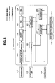
- Fig. 1 is a configuration diagram of a signal processing system according to Embodiment 1 of the present invention
- Fig. 2A through Fig. 2D are explanatory diagrams relating to a local region with a Bayer color filter
- Fig. 3 is a configuration diagram of the selecting unit shown in Fig. 1
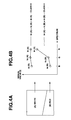
- Fig. 4A through Fig. 4D are explanatory diagrams relating to hue classification based on spectral gradient
- Fig. 5 is a configuration diagram of the noise estimating unit shown in Fig. 1
- Fig. 6A through Fig. 6D are explanatory diagrams relating to noise amount estimation
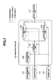
- Fig. 7 is a configuration diagram of the noise reduction unit shown in Fig. 1
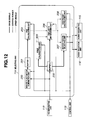
- Fig. 8 is a configuration diagram of a signal processing system according to another form of Embodiment 1
- Fig. 9 is a flow chart of noise reduction processing with Embodiment 1.
- Fig. 1 is a configuration diagram of Embodiment 1 of the present invention.
- Signals from the A/D 106 are transferred to an extracting unit 112 via a buffer 107.
- the buffer 107 is also connected to a pre-white balance (hereafter abbreviated as "Pre WB”) unit 108, exposure control unit 109, and focus control unit 110.
- Pre WB pre-white balance
- the Pre WB unit 108 is connected to the Gain 105
- the exposure control unit 109 is connected to the aperture 101, CCD 103, and Gain 105
- the focus control unit 110 is connected to an AF motor 111.
- Signals from the extracting unit 112 are connected to a Y/C separating unit 113 and selecting unit 114.
- the Y/C separating unit 113 is connected to the selecting unit 114
- the selecting unit 114 is connected to a noise estimating unit 115 and a noise reduction unit 116.
- the noise reduction unit 116 is connected to an output unit 118 such as a memory card or the like via a signal processing unit 117.
- a control unit 119 such as a micro-computer or the like is bi-directionally connected to the CDS 104, Gain 105, A/D 106, Pre WB unit 108, exposure control unit 109, focus control unit 110, extracting unit 112, Y/C separating unit 113, selecting unit 114, noise estimating unit 115, noise reduction unit 116, signal processing unit 117, and output unit 118.
- an external I/F unit 120 having a power switch, shutter button, and an interface for switching various types of photographic modes.
- signals from a temperature sensor 121 disposed near the CCD 103 are also connected to the control unit 119.
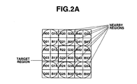
- Fig. 2A illustrates the configuration of a Bayer color filter.
- the basic unit of a Bayer filter is 2 ⁇ 2 pixels, with one pixel each of red (R) and blue (B), and two pixels of green (G), disposed.
- the analog signals are amplified by a predetermined amount at the Gain 105, and a converted into digital signals at the A/D 106 and transferred to the buffer 107.
- the A/D 106 performs conversion into digital signals in 12-bit scale.
- Image signals within the buffer 107 are transferred to the Pre WB unit 108, the photometry evaluation unit 109, and the focus control unit 110.
- the Pre WB unit 108 calculates a brief white balance coefficient by accumulating each color signal by a signal with a specified luminance level in the image signal. The coefficient is transferred to the Gain 105, and white balance is carried out by performing multiplication of different gains for each color signal.
- the exposure control unit 109 determines the luminance level of the image signal, and controls an aperture value of the aperture 101, an electric shutter speed of the CCD 103, an amplification rate of the Gain 105 and the like in consideration of the ISO sensitivity and shutter speed of the limit of image stability or the like, so that an appropriate exposure is obtained.
- the focus control unit 110 detects edge intensity in the signals, and obtains focused signals by controlling the AF motor 111 such that the edge intensity is maximum.
- main shooting is performed by fully pressing the shutter button via the external I/F unit 120, and the image signals are transferred to the buffer 107 in the same way as with the pre-shooting.
- the main shooting is performed based on the white balance coefficient obtained at the Pre WB unit 108, the exposure conditions obtained at the photometry evaluation unit 109, and the focus conditions obtained at the focus control unit 110, and these conditions for each shooting operation are transferred to the control unit 119.
- the image signal within the buffer 107 are transferred to the extracting unit 112.
- the extracting unit 112 sequentially extracts local regions, constructed of a target region and nearby regions as shown in Fig. 2A, under the control of the control unit 119, and transfers to the Y/C separating unit 113 and the selecting unit 114.
- the Y/C separating unit 113 calculates luminance signals Y and color difference signals Cb, and Cr from the target region and nearby regions, under control of the control unit 119. Note that an RGB primary color filter is assumed in the present embodiment, and the luminance signals and color difference signals are calculated based on Expression (1).
- R AV , G AV , B AV mean the average values of R, G, and B, at the target region and nearby regions.
- the calculated luminance signals and color difference signals are transferred to the selecting unit 114.
- the selecting unit 114 selects nearby regions similar to the target region, using the local region from the extracting unit 112 and the luminance signals and color difference signals from the Y/C separating unit 113, under the control of the control unit 119.
- the target region and the selected nearby regions, and the corresponding luminance signals and color difference signals, are transferred to the noise estimating unit 115 and noise reduction unit 116.
- a weighting coefficient is calculated for the selected nearby regions, and is transferred to the noise estimating unit 115.
- the noise estimating unit 115 estimates the amount of noise based on the target region from the extracting unit 112, the selected nearby regions, the luminance signals and color difference signals, and the weighting coefficient, and other information at each shooting operation, under control of the control unit 119, and transfers this to the noise reduction unit 116.
- the noise reduction unit 116 performs noise reduction processing based on the target region from the extracting unit 112 and the luminance signals and color difference signals and the noise amount from the noise estimating unit 115, under control of the control unit 119, and transfers the processed target region to the signal processing unit 117.
- the processing performed at the extracting unit 112, Y/C separating unit 113, selecting unit 114, noise estimating unit 115, and noise reduction unit 116, is performed in synchronization in unit of local region under control of the control unit 119.
- the signal processing unit 117 performs known enhancement processing, compression processing, and the like, on the noise-reduced image signals, under control of the control unit 119, and transfers to the output unit 118.
- the output unit 118 records and saves signals in a memory card or the like.
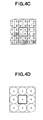
- Fig. 2A through Fig. 2D are explanatory diagrams relating to local regions in a Bayer type primary color filter.
- Fig. 2A illustrates the configuration of a local region of 6 ⁇ 6 pixels
- Fig. 2B illustrates separation into luminance/color difference signals
- Fig. 2C illustrates a different form of a local region of 6 ⁇ 6 pixels
- Fig. 2D illustrates a different form of a local region of 10 ⁇ 10 pixels.
- Fig. 2A illustrates the configuration of a local region according to the present embodiment.
- 2 ⁇ 2 pixels make up the target region, and eight nearby regions of 2 ⁇ 2 pixels each surround the target region, with a local region of a size of 6 ⁇ 6 pixels.
- the local region is extracted by the extracting unit 112 in a two-row two-column overlapping manner, so that the target region covers all of the signals.
- Fig. 2B illustrates the luminance signals and the color difference signals calculated based on Expression (1) at the target region and the nearby regions.
- the luminance signals and the color difference signals at the target region are represented by Yo, Cb 0 , and Cr 0
- the processing performed at the Y/C separating unit 113 is performed in a single CCD state, so one set of luminance signals and color difference signals are calculated for the target region and the nearby regions, respectively. If we say that the target region is configured of the pixels R 22 , G 32 , G 23 , B 33 , as shown in Fig.
- 2D shows another configuration of a local region having a 10 ⁇ 10 pixel size, the bearby regions being constructed of four regions each of which includes 2 ⁇ 2 pixels and four regions each of which includes 3 ⁇ 3 pixels, disposed sparsely within the local region.
- the target region and nearby regions can be configured in any way as long there are one or more sets of R,G, B necessary for calculating luminance signals and color difference signals.
- Fig. 3 illustrates an example of the configuration of the selecting unit 114, and includes a minute fluctuation elimination unit 200, first buffer 201, gradient calculating unit 202, hue calculating unit 203, hue class ROM 204, second buffer 205, similarity determining unit 206, nearby region selecting unit 207, and coefficient calculating unit 208.
- the extracting unit 112 is connected to the hue calculating unit 203 via the fluctuation elimination unit 200, first buffer 201, and gradient calculating unit 202.
- the hue class ROM 204 is connected to the hue calculating unit 203.
- the Y/C separating unit 113 is connected to the similarity determining unit 206 and nearby region selecting unit 207 via the second buffer 205.
- the hue calculating unit 203 is connected to the similarity determining unit 206, and the similarity determining unit 206 is connected to the nearby region selecting unit 207 and the coefficient calculating unit 208.
- the nearby region selecting unit 207 is connected to the noise estimating unit 115 and the noise reduction unit 116.
- the coefficient calculating unit 208 is connected to the noise estimating unit 115.
- the control unit 119 is bi-directionally connected to the minute fluctuation elimination unit 200, gradient calculating unit 202, hue calculating unit 203, similarity determining unit 206, nearby region selecting unit 207, and coefficient calculating unit 208.
- the local region from the extracting unit 112 is transferred to the minute fluctuation elimination unit 200 under control of the control unit 119, and predetermined minute fluctuation components are removed. This is performed by removing lower order bits of the image signals.
- the A/D 106 is assumed to digitize on a 12-bit scale, wherein the lower order 4 bits are shifted so as to remove minute fluctuation components, thereby converting into 8-bit signals and transferring to the first buffer 201.
- the gradient calculating unit 202, hue calculating unit 203, and hue class ROM 204 obtain the spectral gradient for RGB for the target region and nearby regions with regard to the local region in the first buffer 201, under control of the control unit 119, and transfer this to the similarity determining unit 206.
- Fig. 4A through Fig. 4D are explanatory diagrams relating to hue classification based on spectral gradient.
- Fig. 4A illustrates an input image
- Fig. 4B illustrates hue classification based on spectral gradient
- Fig. 4C illustrates CCD output signals
- Fig. 4D illustrates the results of hue classification.
- Fig. 4A illustrates an example of an input image, wherein we will say that the upper A region is white and the lower B region is red.
- This will be taken as class 4.
- Table 1 illustrates the 13 hue classes based on spectral gradient.
- Spectral gradient is obtained for each of the target region and the nearby regions, however, each region has two G signals. This is processed by obtaining the average value and taking this as the G signal.
- Fig. 4D illustrates the target region and the nearby regions being assigned with the classes 0 through 12 as described above, and the classified image is output to the similarity determining unit 206.
- the gradient calculating unit 202 obtains the large-and-small relationship of RGB signals in increments of the target region and nearby regions, and transfers this to the hue calculating unit 203.
- the hue calculating unit 203 calculates the 13 hue classes based on the large-and-small relationship of RGB signals from the gradient calculating unit 202 and the information relating to hue classes from the hue class ROM 204, and transfers these to the similarity determining unit 206.
- the hue class ROM 204 stores the information relating to the spectral gradient and the 13 hue classes shown in Table 1.
- the luminance signals and color difference signals from the Y/C separating unit 113 is saved in the second buffer 205.
- the similarity determining unit 206 reads in the luminance signals for the target region and the nearby regions, under control of the control unit 119.
- the similarity determining unit 206 determines the similarity between the target region and the nearby regions, based on the hue class from the hue calculating unit 203, and the luminance signals.
- Nearby regions which satisfy the conditions of "the same hue class as the target region” and "luminance signals Y i of the nearby region belong to a range within ⁇ 20% of the luminance signals Y 0 of the target region" are determined to have high similarity, and the above determination results are transferred to the nearby region selecting unit 207 and coefficient calculating unit 208.
- the nearby region selecting unit 207 reads out from the second buffer 205 the luminance signals Y i' and color difference signals Cb i' , Cr i' of the nearby region of which similarity has been determined to be high by the determining unit 206, under the control of the control unit 119, and transfers this to the noise estimating unit 115.
- the luminance signals Y 0 and color difference signals Cb 0 , Cr 0 of the target region are read out from the second buffer 205, and transferred to the noise estimating unit 115 and noise reduction unit 116.
- the coefficient calculating unit 208 calculates a weighting coefficient W i' for a nearby region of which similarity has been determined to be high. This is calculated based on Expression (3).
- the calculated weighting coefficient W i' is transferred to the noise estimating unit 115.
- Fig. 5 illustrates an example of the configuration of the noise estimating unit 115, including a buffer 300, average calculating unit 301, gain calculating unit 302, standard value assigning unit 303, parameter ROM 304, parameter selecting unit 305, interpolation unit 306, and correcting unit 307.
- the selecting unit 114 is connected to the buffer 300 and the average calculating unit 301.
- the buffer 300 is connected to the average calculating unit 301, and the average calculating unit 301 is connected to the parameter selecting unit 305.
- the gain calculating unit 302, standard value assigning unit 303, and parameter ROM 304 are connected to the parameter selecting unit 305.
- the parameter selecting unit 305 is connected to the interpolation unit 306 and correcting unit 307.
- the control unit is bi-directionally connected to the average calculating unit 301, gain calculating unit 302, standard value assigning unit 303, parameter selecting unit 305, interpolation unit 306, and correcting unit 307.
- the average calculating unit 301 reads in the luminance signals and the color difference signals from the buffer 300 under control of the control unit 119, and calculates the average values AV Y , AV Cb , and AV Cr of the luminance signals and color difference signals as to the local region, using the weighting coefficient.
- AV Y Y 0 + ⁇ j ⁇ i ⁇ Y j ⁇ W j / 2
- AV Cb Cb 0 + ⁇ j ⁇ i ⁇ Cb j ⁇ W j / 2
- AV Cr Cr 0 + ⁇ j ⁇ i ⁇ Cr j ⁇ W j / 2
- the gain calculating unit 302 calculates the amplification amount at the Gain 105 based on information such as the ISO sensitivity, exposure conditions, and white balance coefficient transferred from the control unit 119, and transfers this to the parameter selecting unit 305.
- control unit 119 obtains the temperature information of the CCD 103 from the temperature sensor 121, and transfers this to the parameter selecting unit 305.
- the parameter selecting unit 305 estimates the amount of noise based on the average values of the luminance signals and the color difference signals from the average calculating unit 301, the gain information from the gain calculating unit 302, and the temperature information from the control unit 119.
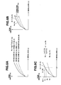
- Fig. 6A through Fig. 6D are explanatory diagrams relating to estimation of noise amount.
- Fig. 6A illustrates the relation of noise amount as to signal level
- Fig. 6B illustrates simplification of a noise model
- Fig. 6C illustrates a noise amount calculation method from the simplified noise model
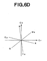
- Fig. 6D illustrates six hues for a color noise model.
- ⁇ s , ⁇ s , and ⁇ s are constant terms.
- the noise amount changes not only with the signal level but also with the device temperature and gain.
- Fig. 6A plots the noise amount with regard to three types of ISO sensitivity, 100, 200, and 400, relating to gain as one example.
- this illustrates noise amount corresponding to onefold, twofold, and fourfold of the gain.
- this illustrates noise amount for the average values at three environment temperatures of 20, 50, and 80°C.
- Each curve takes the form shown in Expression (5), but the coefficients thereof differ according to the ISO sensitivity relating to the gain.
- Formulating a model taking into consideration the above, with the temperature as t and the gain as g yields the following expression 6.
- N s ⁇ sgt L 2 + ⁇ sgt L + ⁇ sgt
- ⁇ sgt are constant terms.
- Fig. 6B a model which gives maximal noise amount is selected as a reference noise mode, and this is approximated with a predetermined number of broken lines. Inflection points of a broken line are represented by coordinate data (L n , N n ) of signal level L and noise amount N. Here, n represents the number of inflection points. Further, a correction coefficient k sgt for deriving other noise models from the reference noise model is also provided. The correction coefficient k sgt is calculated by least-square from the noise models and the reference noise model.
- Fig. 6C illustrates a method for calculating the noise amount from the simplified noise model shown in Fig. 6B.
- N s the amount of noise N s corresponding to the given signal level 1
- a search is made in order to ascertain the interval of the reference noise model to which the signal level l belongs.
- the signal level belongs to the section between (L n , N n ) and (L n +1, N n +1).
- the reference noise amount N 1 in the reference noise model is obtained by linear interpolation.
- N l N n + 1 - N n L n + 1 - L n ⁇ l - L n + N n
- N s k sgt ⁇ N 1
- the above reference noise model can be divided into a reference luminance noise model related to luminance signals and a reference color difference noise model related to color difference signals, but these are basically of the same configuration. Note that while there is only one set of reference luminance noise model and correction coefficient for the luminance signals Y, the amount of color noise differs regarding the color difference signals Cb and Cr depending on the hue direction.
- the coordinate data (L n , N n ) of the inflection points of the reference noise model relating to the luminance and color difference signals, and the correction coefficient k sgt are recorded in the parameter ROM 304.
- the parameter selecting unit 305 sets the signal level 1 from the average values AV Y , A V Cb , and A V Cr of the luminance signals and color difference signals from the average calculating unit 301, the gain g from the gain information from the gain calculating unit 302, and the temperature t from the temperature information from the control unit 119. Further, the hue signal H is obtained from the average values AV Cb , AV Cr of the color difference signals based on Expression (9), and the hue closest to the hue signal H is selected from the six hues R, G, B, Cy, Mg, and Ye, thereby setting Cb_H and Cr_H.
- the interpolation unit 306 calculates the reference noise amount N 1 in the reference noise model from the signal level 1 from the parameter selecting unit 305 and the coordinate data (L n , N n ) and (L n +1, N n +1) based on Expression (7), under control of the control unit 119, and transfers this to the correction unit 307.
- the correction unit 307 calculates the noise amount N s from the correction coefficient k sgt from the parameter selecting unit 305 and the reference noise amount N 1 from the interpolation unit 306 based on Expression (8) under the control of the control unit 119, and transfers this to the noise reduction unit 116 along with the average values AV Y , AV Cb , and AV Cr of the luminance signals and color difference signals.
- Fig. 7 illustrates an example of the configuration of the noise reduction unit 116, including a range setting unit 400, a switching unit 401, a first smoothing unit 402, and a second smoothing unit 403.
- the noise estimating unit 115 is connected to the range setting unit 400, and the range setting unit 400 is connected to the switching unit 401, first smoothing unit 402, and second smoothing unit 403.
- the selecting unit 114 is connected to the switching unit 401, and the switching unit 401 is connected to the first smoothing unit 402 and second smoothing unit 403.
- the first smoothing unit 402 and second smoothing unit 403 are connected to the signal processing unit 117.
- the control unit 119 is bi-directionally connected to the range setting unit 400, switching unit 401, first smoothing unit 402, and second smoothing unit 403.
- the noise estimating unit 115 transfers the average values AV Y , AV Cb , and AV Cr of the luminance signals and color difference signals, and the noise amount N s , to the range setting unit 400.
- the range setting unit 400 sets the upper limit U s and lower limit D s as a permissible range for the noise amount of the luminance signals and color difference signals as shown in Expression (10), under the control of the control unit 119.
- the above permissible ranges U s and D s are transferred to the switching unit 401.
- the range setting unit 400 transfers the average values AV Y , AV Cb , and AV Cr of the luminance signals and color difference signals, and the noise amount N s , to the first smoothing unit 402, and second smoothing unit 403.
- the switching unit 401 reads in the luminance signals Y 0 and color difference signals Cb 0 , Cr 0 of the target region from the selecting unit 114 under the control of the control unit 119, and performs determination regarding whether or not these belong to the above permissible ranges. There are three ways that determination is made, namely, "belonging to the noise range", “above the noise range”, and “below the noise range”.
- the switching unit 401 transfers the luminance signals Y 0 and color difference signals Cb 0 , Cr 0 of the target region to the first smoothing unit 402, and otherwise transfers these to the second smoothing unit 403.
- the first smoothing unit 402 performs processing for substituting the average values AV Y , AV Cb , and AV Cr of the luminance signals and color difference signals from the range setting unit 400 into the luminance signals Y 0 and color difference signals Cb 0 , Cr 0 of the target region from the switching unit 401.
- the processing in Expression (11) can be converted as shown in Expression (12), based on Expression (2).
- the processing in Expression (12) means that the target region which has been subjected to processing in the form of luminance signals Y 0 and color difference signals Cb 0 , Cr 0 is returned to the original RGB signals.
- the RGB signals in Expression (12) are transferred to the signal processing unit 117.
- the second smoothing unit 403 performs processing for correcting the luminance signals Y 0 and color difference signals Cb 0 , Cr 0 of the target region from the switching unit 401 using the average value AV Y and noise amount N s of the luminance signals from the range setting unit 400.
- correction is performed as in Expression (13).
- Y 0 Y 0 - N Y / 2
- Cb 0 Cb 0 - N Cb / 2
- Cr 0 Cr 0 - N Cr / 2
- Expression (14) or Expression (16) also means that the target region which has been subjected to processing in the form of luminance signals Y 0 and color difference signals Cb 0 , Cr 0 is returned to the original RGB signals.
- the RGB signals in Expression (14) or Expression (16) are transferred to the signal processing unit 117.
- noise amount estimation corresponding to the dynamically changing conditions such as signal level, the temperature and gain for each shooting operation and so on, and optimal noise reduction for the entire image is enabled, so high-quality signals can be obtained. Even in the case that the above information cannot be obtained, standard values are used to estimate the noise amount, so stable noise reduction effects can be obtained.
- the target region and similar nearby regions regarding which noise reduction processing is to be performed are selected based on hue and luminance information, following which these are processed together, so noise amount estimation can be performed using a larger area, whereby the precision of estimation can be improved.
- the amount of memory needed for the model is small, whereby reductions in cost can be made.
- the noise reduction processing is performed setting a permissible range based on the noise amount, so reduction processing can be performed wherein preservation of original signals is excellent and occurrence of discontinuity is prevented.
- post-noise-reduction-processing signals are output as the original signals, so compatibility with conventional processing systems is maintained, enabling combination with various systems.
- luminance signals and color difference signals are obtained based on the Bayer type color filter placement, thereby enabling high-speed processing.
- noise amount estimation and noise reduction processing is performed using all of the selected nearby regions, but there is no need to be restricted to such a configuration. Rather, configurations may be freely made, such as for example, the nearby regions in the diagonal direction from the target region being eliminated in noise amount estimation, so as to improve the precision by performing estimation in a relatively narrow region, and all selected nearby regions being used in the noise reduction processing so as to improve smoothing capabilities by performing the processing in relatively wide region, and so forth.
- the signal processing system is of a configuration integrally formed with the image pickup unit of the lens system 100, aperture 101, low-pass filter 102, CCD 103, CDS 104, Gain 105, A/D 106, Pre WB unit 108, exposure control unit 109, focus control unit 110, AF motor 111, and temperature sensor 121, but there is no need to be restricted to such a configuration.
- Fig. 1 As shown in Fig.
- Fig. 8 shows an arrangement wherein the lens system 100, aperture 101, low-pass filter 102, CCD 103, CDS 104, Gain 105, A/D 106, Pre WB unit 108, exposure control unit 109, focus control unit 110, AF motor 111, and temperature sensor 121 are omitted from the configuration shown in Fig. 1, and an input unit 500 and header information analysis unit 501 are added.
- the basic configuration is equivalent to that in Fig. 1, and the same components are assigned with the same names and numerals. Now, only the different portions will be described.
- the input unit 500 is connected to the buffer 107 and the header information analysis unit 501.
- the control unit 119 is bi-directionally connected to the input unit 500 and the header information analysis unit 501.
- the external I/F unit 120 such as a mouse, keyboard, and the like, allows the signals and the header information saved in the recording medium such as a memory card, to be read in from the input unit 500.
- the signals from the input unit 500 are transferred to the buffer 107, and the header information is transferred to the header information analysis unit 501.
- the header information analysis unit 501 extracts information at each shooting operation from the header information, and transfers this to the control unit 119. Subsequent processing is equivalent to that in Fig. 1.
- Fig. 9 illustrates a flow relating to software processing of the noise reduction processing.
- header information such as signals and temperature, gain, and so forth, are read in.
- step S2 a local region configured of the target region and nearby regions such as shown in Fig. 2A, is extracted.
- the luminance signals and color difference signals are separated as shown in Expression (1).
- step S4 the target region and the nearby regions within the local region are classified into hue classes, such as shown in Table 1.
- step S5 the similarity of each of the nearby regions and the target region is determined, based on the hue class information from step S4 and the luminance information from step S3.
- step S6 the weighting coefficient shown in Expression (3) is calculated.
- step S7 the luminance signals and color difference signals of the target region and the nearby regions determined to have high similarity based on the similarity from step S5 are selected from step S3.
- step S8 the average values of the luminance signals and color difference signals, shown in Expression (4), are calculated.
- step S9 information such as temperature, gain, and the like, are set from the header information that has been read in. In the case that necessary parameters do not exist in the header information, predetermined standard values are assigned.
- step S 10 coordinate data of the reference noise model, and a correction coefficient, are read in.
- step S11 the reference noise amount is obtained by the interpolation processing shown in Expression (7).
- step S 12 the amount of noise is obtained by the correction processing shown in Expression (8).
- step S 13 determination is made regarding whether or not the luminance signals and color difference signals of the target region belong within the permissible range shown in Expression (10), and the flow branches to step S14 in the case of belonging, and to step S 15 in the case of not belonging.
- step S 14 the processing shown in Expression (12) is performed.
- step S 15 the processing shown in Expression (14) and Expression (16) is performed.
- step S16 a judgment is made as to whether or not the extraction of all local regions has been completed, in cases where the extraction has not been completed, the processing returns to the abovementioned step S2, while in a case where the extraction has been completed, the processing proceeds to step S 17.
- step S 17 known enhancing processing and compression processing and the like are performed.
- step S18 the processed signals are output, and the flow ends.
- Fig. 10 is a configuration diagram of a signal processing system according to Embodiment 2 of the present invention
- Fig. 11A through Fig. 11C are explanatory diagrams relating to a local region in a color difference line sequential color filter
- Fig. 12 is a configuration diagram of the selecting unit shown in Fig. 10
- Fig. 13 is a configuration diagram of the selecting unit according to another configuration
- Fig. 14 is a configuration diagram of the noise estimating unit shown in Fig. 10
- Fig. 15 is a flow chart of noise reduction processing with Embodiment 2.
- Fig. 10 is a configuration diagram of Embodiment 2 of the present invention.
- the present embodiment is a configuration wherein the connection from the extracting unit 112 to the selecting unit 114 in Embodiment 1 of the present invention has been deleted.
- the basic configuration is equivalent to that in Embodiment 1, and the same components are assigned with the same names and numerals.
- Image signals captured via the lens system 100, aperture 101, low-pass filter 102, and CCD 103, are transferred to the buffer 107.
- Fig. 11A illustrates the configuration of a color difference line sequential type color filter.
- Fig. 11A illustrates the configuration of an 8 ⁇ 8 pixel local region,
- Fig. 11B illustrates separation into luminance/color difference signals, and
- Fig. 11C illustrates extracting of edge components.
- 2 ⁇ 2 pixels is the basic unit, with one pixel each of cyan (Cy), magenta (Mg), yellow (Ye), and green (G) being provided. Note however, that the positions of Mg and G are inverted each line.
- the image signals in the buffer 107 are transferred to the extracting unit 112.
- the extracting unit 112 sequentially extracts 8 ⁇ 8 pixel local regions constructed of a 4 ⁇ 4 pixel target region and 4 ⁇ 4 pixel nearby regions as shown in Fig. 11 A, under the control of the control unit 119, and transfers these to the Y/C separating unit 113 and the selecting unit 114.
- the extracting unit 112 extracts the local regions in a two-row two-column overlapping manner, so that the target region covers all signals.
- the Y/C separating unit 113 calculates the luminance signals Y and color difference signals Cb, Cr from the region of the interest and the nearby regions in 2 ⁇ 2 pixel units based on Expression (17), under the control of the control unit 119.
- Fig. 11 B illustrates luminance signals and color difference signals calculated based on the Expression (17) in the target region and nearby regions as a unit.
- the calculated luminance signals and color difference signals are transferred to the selecting unit 114.
- the selecting unit 114 selects nearby regions similar to the target region using the luminance signals and color difference signals from the Y/C separating unit 113, under the control of the control unit 119.
- the target region and selected nearby regions, and the corresponding luminance signals and color difference signals, are transferred to the noise estimating unit 115 and noise reduction unit 116.
- a weighting coefficient relating to the selected nearby regions is calculated, and transferred to the noise estimating unit 115.
- the noise estimating unit 115 estimates the noise amount based on the target region, the selected nearby regions, luminance signals, color difference signals, and weighting coefficient from the extracting unit 112, and other information at each shooting operation, and transfers this to the noise reduction unit 116, under the control of the control unit 119.
- the noise reduction unit 116 performs noise reduction processing of the target region based on the target region, luminance signals, and color difference signals from the extracting unit 112, and the noise amount from the noise estimating unit 155, under control of the control unit 119, and transfers the processed target region to the signal processing unit 117.
- the processing at the extracting unit 112, Y/C separating unit 113, selecting unit 114, noise estimating unit 115, and noise reduction unit 116, is performed synchronously in a local region as a unit, under the control of the control unit 119.
- the signal processing unit 117 performs known enhancement processing and compression processing and the like on the image signals following noise reduction, and outputs to the output unit 118, under the control of the control unit 119.
- the output unit 118 records and saves the signals to the memory card or the like.
- Fig. 12 illustrates an example of the configuration of the selecting unit 114 in Fig. 10, and is of a configuration wherein an edge calculating unit 600 is added to the selecting unit 114 shown in Fig. 3 in Embodiment 1 of the present invention, and the gradient calculating unit 202 and the hue class ROM 204 are deleted from the selecting unit 114 shown in Fig. 3 in Embodiment 1 of the present invention.
- the basic configuration is equivalent to the selecting unit 114 shown in Fig. 3, and the same components are assigned with the same names and numerals. The following is a description of only the different portions.
- the Y/C separating unit 113 is connected to the minute fluctuation elimination unit 200.
- the minute fluctuation elimination unit 200 is connected to the hue calculating unit 203 via the first buffer 201.
- the second buffer 205 is connected to the edge calculating unit 600, and the edge calculating unit 600 is connected to the similarity determining unit 206.
- the control unit 119 is connected bi-directionally to the edge calculating unit 600.
- Luminance signals and color difference signals from the target region and the nearby regions from the Y/C separating unit 113 are transferred to the minute fluctuation elimination unit 200 and the second buffer 205.
- the minute fluctuation elimination unit 200 removes minute fluctuation components by performing lower-order bit shift processing for the color difference signals, and transfers to the first buffer 201.
- the hue calculating unit 203 calculates hue signals H based on Expression (9), from the color difference signals of the target region and the nearby regions of the first buffer 201, under the control of the control unit 119.
- the edge calculating unit 600 reads in the luminance signals of the target region and the nearby regions from the second buffer 205, under the control of the control unit 119.
- An edge intensity value E is calculated by applying the 3 ⁇ 3 Laplacian operator shown in Expression (18) to the luminance signals for each region. Expression 18 - 1 - 1 - 1 - 1 8 - 1 - 1 - 1 - 1 - 1
- the target region and the nearby regions have nine points each of luminance signals as shown in Fig.
- the similarity determining unit 206 reads in the luminance signals of the target region and the nearby regions from the second buffer 205, under the control of the control unit 119.
- the similarity determining unit 206 determines the similarity between the target region and the nearby regions, based on the hue signals from the hue calculating unit 203 and the edge intensity values from the edge calculating unit 600 and the luminance signals.
- a nearby region which satisfies the conditions of "hue signal H i of the nearby region belonging to a range of ⁇ 25% of the hue signal H 0 of the target region” and "edge intensity value E i of the nearby region belonging to a range of ⁇ 20% of the edge intensity value E 0 of the target region” and "luminance signal Yi of the nearby region belonging to a range of ⁇ 20% of the luminance signal Y 0 of the target region” is determined as having high similarity, and the determination results are transferred to the nearby region selecting unit 207 and coefficient calculating unit 208. Subsequent processing is the same as with Embodiment 1 according to the present invention shown in Fig. 3.
- Fig. 13 is a diagram wherein the edge calculating unit 600 in Fig. 12 has been replaced with a DCT conversion unit 700, and the basic configuration thereof is equivalent to the selecting unit 114 shown in Fig. 12, with the same names and numerals being assigned to the same components. Now, only the different portions will be described.
- the second buffer 205 is connected to the DCT conversion unit 700, and the DCT conversion unit 700 is connected to the similarity determining unit 206.
- the control unit 119 is connected bi-directionally with the DCT conversion unit 700.
- the DCT conversion unit 700 reads in luminance signals of the target region and nearby regions from the second buffer 205, under the control of the control unit 119.
- Known DCT conversion is performed on the luminance signals of each of the regions.
- the frequency signals after conversion are transferred to the similarity determining unit 206.
- the similarity determining unit 206 determines the similarity of the target region and nearby regions based on the hue signals from the hue calculating unit 203 and the frequency signals and luminance signals from the DCT conversion unit 700.
- Fig. 14 illustrates an example of the configuration of the noise estimating unit 115 shown in Fig. 10, wherein a look-up table 800 is added to the noise estimating unit 115 shown in Fig. 5 according to Embodiment 1 of the present invention, and the parameter ROM 304, parameter selecting unit 305, interpolation unit 306, and correction unit 307 are omitted therefrom.
- the basic configuration is equivalent to the noise estimating unit 115 shown in Fig. 5, and the same names and numerals are assigned to the same components. Now, only the different portions will be described.
- the average calculating unit 301, gain calculating unit 302, and standard value assigning unit 303 are connected to the look-up table 800.
- the look-up table 800 is connected to the noise reduction unit 116.
- the control unit 119 is bi-directionally connected with the look-up table 800.
- the average calculating unit 301 reads in luminance signals and color difference signals from the buffer 300 under the control of the control unit 119, and calculates the average values AV Y , AV Cb , AV Cr of the luminance signals and color difference signals for the local region using a weighting coefficient.
- the average values of the luminance signals and the color difference signals are transferred to the look-up table 800.
- the gain calculating unit 302 obtains the amount of amplification at the Gain 105 based on information relating to the ISO sensitivity and exposure conditions and white balance coefficient, transferred from the control unit 119, and transfers this to the look-up table 800.
- the control unit 119 obtains the temperature information of the CCD 103 from the temperature sensor 121, and transfers this to the look-up table 800.
- the look-up table 800 estimates the noise amount based on the average values of the luminance signals and color difference signals from the average calculating unit 301, the gain information from the gain calculating unit 302, and the temperature information from the control unit 119.
- the look-up table 800 is a look-up table storing the relation between temperature, signal value level, gain, shutter speed, and noise amount, and is configured with a technique equivalent to that in Embodiment 1.
- the noise amount obtained at the look-up table 800 is transferred to the noise reduction unit 116.
- the standard value assigning unit 303 has a function of assigning a standard value in the case that any of parameter has been omitted.
- noise amount estimation corresponding to the dynamically changing conditions such as signal level, the temperature and gain for each shooting operation and so forth, and optimal noise reduction for the entire image, is enabled, so high-quality signals can be obtained. Even in the case that the above information cannot be obtained, standard values are used to estimate the noise amount, so stable noise reduction effects can be obtained. Further, intentionally omitting a part of parameter calculations enables a signal processing system to be provided wherein reduction in costs and energy conservation can be realized. Also, the target region and similar nearby regions regarding which noise reduction processing is to be performed are selected based on hue, luminance, edge, and frequency information, following which these are processed together, so noise amount estimation can be performed using a larger area, whereby the precision of estimation can be improved.
- the noise reduction processing is performed setting a permissible range based on the noise amount, so reduction processing can be performed wherein preservation of original signals is excellent and occurrence of discontinuity is prevented.
- Fig. 15 illustrates a flow chart relating to software processing of the noise reduction processing. Note that the processing steps which are the same as those in the noise reduction processing flow chart of Embodiment 1 of the present invention shown in Fig. 9 are assigned with the same step numbers.
- step S1 header information such as signals and temperature, gain, and so forth, are read in.
- step S2 a local region configured of the target region and nearby regions such as shown in Fig. 11A, is extracted.
- step S3 the luminance signals and color difference signals are separated as shown in Expression (17).
- the hue signals are calculated based on Expression (9) from the target region and nearby regions within the local region.
- an edge intensity value is calculated by applying the Laplacian operator shown in Expression (18).
- step S5 the similarity of each of the nearby regions and the target region is determined, based on the hue information from step S4 and the luminance information from step S3 and the edge information from step S20.
- step S6 the weighting coefficient shown in Expression (3) is calculated.
- step S7 the luminance signals and color difference signals of the target region and the nearby regions determined to have high similarity based on the similarity from step S5 are selected from step S3.
- step S8 the average values of the luminance signals and color difference signals, shown in Expression (4), are calculated.
- step S9 information such as temperature, gain, and the like, are set from the header information that has been read in. In the case that necessary parameters do not exist in the header information, predetermined standard values are assigned.
- step S21 the amount of noise is obtained using the look-up table.
- step S 13 determination is made regarding whether or not the luminance signals and color difference signals of the target region belong within the permissible range shown in Expression (10), and the flow branches to step S14 in the case of belonging, and to step S 15 in the case of not belonging.
- step S 14 the processing shown in Expression (11) is performed.
- step S15 the processing shown in Expression (13) and Expression (15) is performed.
- step S16 determination is made regarding whether or not all local regions have been completed, and the flow branches to step S2 in the case of not being completed, and to step S 17 in the case of being completed.
- step S 17 known enhancing processing and compression processing and the like are performed.
- step S 18 the processed signals are output, and the flow ends.
- modeling is performed for the amount of noise of color signals and luminance signals corresponding not only to signal level but also to factors which dynamically change, such as temperature at each shooting operation, gain, and so forth, thereby enabling noise reduction processing optimized for shooting conditions.
- noise reduction processing is independently performed on both luminance noise and color noise, thereby realizing high-precision reduction of both noises, and generating high-quality signals.
- the present invention can be broadly applied to devices wherein there is a need to reduce, with high precision, random noise of color signals and luminance signals originating at the image pickup device, such as image capturing devices, image reading devices, and so forth.
Applications Claiming Priority (2)
| Application Number | Priority Date | Filing Date | Title |
|---|---|---|---|
| JP2004201091A JP2006023959A (ja) | 2004-07-07 | 2004-07-07 | 信号処理システム及び信号処理プログラム |
| PCT/JP2005/012478 WO2006004151A1 (fr) | 2004-07-07 | 2005-07-06 | Systeme de traitement du signal et programme de traitement du signal |
Publications (1)
| Publication Number | Publication Date |
|---|---|
| EP1764738A1 true EP1764738A1 (fr) | 2007-03-21 |
Family
ID=35782951
Family Applications (1)
| Application Number | Title | Priority Date | Filing Date |
|---|---|---|---|
| EP05757820A Withdrawn EP1764738A1 (fr) | 2004-07-07 | 2005-07-06 | Systeme de traitement du signal et programme de traitement du signal |
Country Status (4)
| Country | Link |
|---|---|
| US (1) | US20070132864A1 (fr) |
| EP (1) | EP1764738A1 (fr) |
| JP (1) | JP2006023959A (fr) |
| WO (1) | WO2006004151A1 (fr) |
Cited By (2)
| Publication number | Priority date | Publication date | Assignee | Title |
|---|---|---|---|---|
| EP2247112A1 (fr) * | 2008-02-07 | 2010-11-03 | Olympus Corporation | Dispositif de traitement d'images et programme de traitement d'images |
| EP2400741A1 (fr) * | 2009-02-18 | 2011-12-28 | Olympus Corporation | Dispositif, procédé et programme de traitement d'image |
Families Citing this family (17)
| Publication number | Priority date | Publication date | Assignee | Title |
|---|---|---|---|---|
| US7583303B2 (en) * | 2005-01-31 | 2009-09-01 | Sony Corporation | Imaging device element |
| JP4265546B2 (ja) * | 2005-01-31 | 2009-05-20 | ソニー株式会社 | 撮像装置、画像処理装置および画像処理方法 |
| JP4660342B2 (ja) * | 2005-10-12 | 2011-03-30 | オリンパス株式会社 | 画像処理システム、画像処理プログラム |
| EP1976268A1 (fr) * | 2005-12-28 | 2008-10-01 | Olympus Corporation | Systeme d'imagerie et programme de traitement d'image |
| JP4959237B2 (ja) | 2006-06-22 | 2012-06-20 | オリンパス株式会社 | 撮像システム及び撮像プログラム |
| JP4653059B2 (ja) | 2006-11-10 | 2011-03-16 | オリンパス株式会社 | 撮像システム、画像処理プログラム |
| JP4523008B2 (ja) | 2007-01-10 | 2010-08-11 | 学校法人神奈川大学 | 画像処理装置および撮像装置 |
| JP5052189B2 (ja) | 2007-04-13 | 2012-10-17 | オリンパス株式会社 | 映像処理装置及び映像処理プログラム |
| JP5165300B2 (ja) | 2007-07-23 | 2013-03-21 | オリンパス株式会社 | 映像処理装置および映像処理プログラム |
| JP5012315B2 (ja) * | 2007-08-20 | 2012-08-29 | セイコーエプソン株式会社 | 画像処理装置 |
| JP2010147568A (ja) * | 2008-12-16 | 2010-07-01 | Olympus Corp | 画像処理装置、画像処理方法、および、画像処理プログラム |
| US9204113B1 (en) * | 2010-06-28 | 2015-12-01 | Ambarella, Inc. | Method and/or apparatus for implementing high dynamic range image processing in a video processing system |
| JP6071419B2 (ja) * | 2012-10-25 | 2017-02-01 | キヤノン株式会社 | 画像処理装置及び画像処理方法 |
| JP6349614B2 (ja) | 2015-05-15 | 2018-07-04 | エスゼット ディージェイアイ テクノロジー カンパニー リミテッドSz Dji Technology Co.,Ltd | 画像処理方法及び画像処理システム |
| US9977986B2 (en) * | 2015-11-19 | 2018-05-22 | Streamax Technology Co, Ltd. | Method and apparatus for switching a region of interest |
| KR20220090920A (ko) * | 2020-12-23 | 2022-06-30 | 삼성전자주식회사 | 이미지 센서, 이미지 센서의 동작 방법 및 이를 포함하는 이미지 센싱 장치 |
| KR20220145694A (ko) * | 2021-04-22 | 2022-10-31 | 에스케이하이닉스 주식회사 | 이미지 센싱 장치 및 그의 동작방법 |
Family Cites Families (4)
| Publication number | Priority date | Publication date | Assignee | Title |
|---|---|---|---|---|
| JP2001157057A (ja) * | 1999-11-30 | 2001-06-08 | Konica Corp | 画像読取装置 |
| JP3689607B2 (ja) * | 1999-12-15 | 2005-08-31 | キヤノン株式会社 | 画像処理方法、装置および記憶媒体 |
| US6980326B2 (en) * | 1999-12-15 | 2005-12-27 | Canon Kabushiki Kaisha | Image processing method and apparatus for color correction of an image |
| JP3893099B2 (ja) * | 2002-10-03 | 2007-03-14 | オリンパス株式会社 | 撮像システムおよび撮像プログラム |
-
2004
- 2004-07-07 JP JP2004201091A patent/JP2006023959A/ja active Pending
-
2005
- 2005-07-06 WO PCT/JP2005/012478 patent/WO2006004151A1/fr not_active Application Discontinuation
- 2005-07-06 EP EP05757820A patent/EP1764738A1/fr not_active Withdrawn
-
2007
- 2007-01-03 US US11/649,924 patent/US20070132864A1/en not_active Abandoned
Non-Patent Citations (1)
| Title |
|---|
| See references of WO2006004151A1 * |
Cited By (6)
| Publication number | Priority date | Publication date | Assignee | Title |
|---|---|---|---|---|
| EP2247112A1 (fr) * | 2008-02-07 | 2010-11-03 | Olympus Corporation | Dispositif de traitement d'images et programme de traitement d'images |
| EP2247112A4 (fr) * | 2008-02-07 | 2012-12-05 | Olympus Corp | Dispositif de traitement d'images et programme de traitement d'images |
| US8441546B2 (en) | 2008-02-07 | 2013-05-14 | Olympus Corporation | Image processing device and image processing program |
| EP2400741A1 (fr) * | 2009-02-18 | 2011-12-28 | Olympus Corporation | Dispositif, procédé et programme de traitement d'image |
| EP2400741A4 (fr) * | 2009-02-18 | 2013-01-02 | Olympus Corp | Dispositif, procédé et programme de traitement d'image |
| US8896727B2 (en) | 2009-02-18 | 2014-11-25 | Olympus Corporation | Image processing apparatus, method, and computer-readable recording medium having image processing program recorded thereon |
Also Published As
| Publication number | Publication date |
|---|---|
| US20070132864A1 (en) | 2007-06-14 |
| WO2006004151A1 (fr) | 2006-01-12 |
| JP2006023959A (ja) | 2006-01-26 |
Similar Documents
| Publication | Publication Date | Title |
|---|---|---|
| EP1764738A1 (fr) | Systeme de traitement du signal et programme de traitement du signal | |
| JP4465002B2 (ja) | ノイズ低減システム、ノイズ低減プログラム及び撮像システム。 | |
| US7656442B2 (en) | Image pickup system, noise reduction processing device and image pick-up processing program | |
| US8184924B2 (en) | Image processing apparatus and image processing program | |
| JP3899118B2 (ja) | 撮像システム、画像処理プログラム | |
| US8194160B2 (en) | Image gradation processing apparatus and recording | |
| JP3762725B2 (ja) | 撮像システムおよび画像処理プログラム | |
| JP5034003B2 (ja) | 画像処理装置 | |
| US8310566B2 (en) | Image pickup system and image processing method with an edge extraction section | |
| US8115833B2 (en) | Image-acquisition apparatus | |
| US7916187B2 (en) | Image processing apparatus, image processing method, and program | |
| JP2004312467A (ja) | 撮像システム、画像処理プログラム | |
| US8223226B2 (en) | Image processing apparatus and storage medium storing image processing program | |
| WO2008056565A1 (fr) | Système d'analyse d'image et programme de traitement d'image | |
| US8320714B2 (en) | Image processing apparatus, computer-readable recording medium for recording image processing program, and image processing method | |
| EP1944982A1 (fr) | Systeme et programme de traitement d'image | |
| US8154630B2 (en) | Image processing apparatus, image processing method, and computer readable storage medium which stores image processing program | |
| WO2008150017A1 (fr) | Procédé de traitement de signal et dispositif de traitement de signal | |
| JP5372586B2 (ja) | 画像処理装置 | |
| US8351695B2 (en) | Image processing apparatus, image processing program, and image processing method | |
| JP4831941B2 (ja) | 撮像処理システム、プログラム及び記憶媒体 |
Legal Events
| Date | Code | Title | Description |
|---|---|---|---|
| PUAI | Public reference made under article 153(3) epc to a published international application that has entered the european phase |
Free format text: ORIGINAL CODE: 0009012 |
|
| 17P | Request for examination filed |
Effective date: 20061129 |
|
| AK | Designated contracting states |
Kind code of ref document: A1 Designated state(s): DE FR GB |
|
| RBV | Designated contracting states (corrected) |
Designated state(s): DE FR GB |
|
| DAX | Request for extension of the european patent (deleted) | ||
| STAA | Information on the status of an ep patent application or granted ep patent |
Free format text: STATUS: THE APPLICATION HAS BEEN WITHDRAWN |
|
| 18W | Application withdrawn |
Effective date: 20100503 |