EP1764591A2 - Dispositif destiné à la mesure de niveaux de remplissage dans un réservoir d'essence - Google Patents
Dispositif destiné à la mesure de niveaux de remplissage dans un réservoir d'essence Download PDFInfo
- Publication number
- EP1764591A2 EP1764591A2 EP06120433A EP06120433A EP1764591A2 EP 1764591 A2 EP1764591 A2 EP 1764591A2 EP 06120433 A EP06120433 A EP 06120433A EP 06120433 A EP06120433 A EP 06120433A EP 1764591 A2 EP1764591 A2 EP 1764591A2
- Authority
- EP
- European Patent Office
- Prior art keywords
- waveguide
- fuel tank
- transmitting
- signal
- radar signal
- Prior art date
- Legal status (The legal status is an assumption and is not a legal conclusion. Google has not performed a legal analysis and makes no representation as to the accuracy of the status listed.)
- Withdrawn
Links
Images

Classifications
-
- G—PHYSICS
- G01—MEASURING; TESTING
- G01F—MEASURING VOLUME, VOLUME FLOW, MASS FLOW OR LIQUID LEVEL; METERING BY VOLUME
- G01F23/00—Indicating or measuring liquid level or level of fluent solid material, e.g. indicating in terms of volume or indicating by means of an alarm
- G01F23/22—Indicating or measuring liquid level or level of fluent solid material, e.g. indicating in terms of volume or indicating by means of an alarm by measuring physical variables, other than linear dimensions, pressure or weight, dependent on the level to be measured, e.g. by difference of heat transfer of steam or water
- G01F23/28—Indicating or measuring liquid level or level of fluent solid material, e.g. indicating in terms of volume or indicating by means of an alarm by measuring physical variables, other than linear dimensions, pressure or weight, dependent on the level to be measured, e.g. by difference of heat transfer of steam or water by measuring the variations of parameters of electromagnetic or acoustic waves applied directly to the liquid or fluent solid material
- G01F23/284—Electromagnetic waves
Definitions
- the invention relates to a device for measuring levels in a fuel tank with a signal source for generating at least one radar signal, with a transmitting and receiving device for emitting the radar signal and for receiving a radar signal reflected by a fluid and an evaluation unit, which in dependence of reflected radar signal generates a level corresponding to the electrical signal.
- the reservoir has an opening into which the Radarmessaku is used with the transmitter, the receiver and the measuring electronics.
- a belonging to Radarmessech flange closes the opening in the reservoir.
- the transmitter and receiver is located within the reservoir.
- a bore in the flange connects the radar electronics to the transmitter and receiver.
- Such free-radiating measuring devices are suitable for stationarily arranged and simply designed containers. In the case of moving fluids, due to non-stationary storage containers, and / or storage containers with a complicated design, considerable difficulties are encountered in obtaining a signal corresponding to the filling level.
- Another disadvantage with aggressive fluids is that both the transmitter and receiver, as well as all other parts of the radar measurement unit associated with the interior of the reservoir, must be resistant to the aggressive fluids.
- lever encoders It is also known to use for level measurement in fuel tanks due to their simple structure provided with a thick-film resistor lever encoder.
- the disadvantage of lever encoders is that the complete level sensor is located in the fuel tank and thus in the fuel.
- the lever encoder therefore requires fuel-resistant materials.
- a lever transmitter due to the pivoting range of its lever arm requires a considerable amount of space that is not always fully available due to today's fuel tank geometries.
- the invention is therefore an object of the invention to provide a device for measuring levels in a fuel tank, which is suitable to determine the level by means of radar in a moving and / or complicated reservoir.
- the object is achieved in that the reservoir is a fuel tank in which a waveguide for the radar signal is arranged.
- the waveguide targeted guidance or process limitation of the radar signal is achieved in order to guide the radar signal in a predetermined range.
- the disturbing effects influencing the measurement can be eliminated or at least minimized in this way.
- the waveguide has small dimensions perpendicular to the course of the measuring section, it requires only a small space, in contrast to a lever transmitter, so that the device according to the invention has wider possibilities of use.
- the waveguide has a high mechanical robustness, which is due to the absence of moving parts.
- the waveguide is a waveguide.
- This training as a waveguide has the advantage in that the fluid in the waveguide is damped with forces acting on the fuel tank. At least the liquid level in the waveguide is subjected to lower movements than the liquid level of the remaining fluid in the fuel tank.
- the measurement by radar can be carried out according to the FMCW method (Frequency Modulated Continuous Wave).
- the frequency band used ranges from 3 GHz to 0.3 GHz.
- a further damping of the fluid contained in the waveguide is achieved with a float arranged in the waveguide.
- the mechanical robustness of the device is not affected by the arrangement of a float as a moving part.
- the improvement in the reflected radar signal is used when the float has a metal layer at least on the side facing the transmitting and receiving unit.
- the float may be a metalized float of nitrophyl.
- a good signal line is achieved according to a further embodiment in that a wire for the signal line is coaxially arranged in the waveguide.
- the waveguide has a shielding effect against external influences in this embodiment.
- the waveguide consists of two wires arranged parallel to each other, which are connected to each other by means of a bridge for the radar signal, wherein the bridge is designed as a float.
- the radar signal is passed over a wire to the float and returned via the float over the other wire back to the transmitting and receiving unit.
- the float thus fulfills two functions.
- This waveguide is operated with the CW method (Continous Wave). The advantage of this method is that the ISM band can be used at a frequency of 433 MHz.
- An improved adaptation to the fuel tank is achieved with a waveguide having a non-linear course.
- Such a configuration of the waveguide increases the possible uses of the measuring device.
- This configuration allows both ends of the waveguide, with respect to the vertical extension, are not arranged one above the other.
- the lower end of the waveguide can be arranged in hard to reach areas of the fuel tank, while the upper end of the waveguide is disposed in an easily accessible area, or vice versa.
- Good accessibility is a prerequisite for easy mounting of the measuring device.
- three-dimensional designs are possible. It only has to be ensured that the fluid to be measured or the float can rise and fall freely within the waveguide without any additional influence, ie. H. siphon-like designs are not possible.
- the waveguide has an oblique course.
- the resolution of the measuring device can be increased in a simple manner, because compared to a vertical arrangement of the waveguide, a longer measuring section is available at the same height.
- the signal source irradiates the radar signal through the container wall into the waveguide and receives the reflected signal through the container wall.
- the external electronics need not be protected by additional protective measures against the fuel. Only internal waveguide is to be designed such that it has the necessary mechanical and chemical robustness, which can be done due to its simple structure without large additional costs.
- Another advantage of the external arrangement is that no additional flange for introducing the measuring device is necessary. Since flanges are always sites of increased permeation of fuel vapors from the fuel tank, with this embodiment, the permeation behavior of the fuel tank is not deteriorated.
- the signal source, the transmitting and receiving device and the evaluation unit are arranged on the underside of the fuel tank.
- This arrangement has the advantage that the measuring device is ground referenced. Soil referencing is important in that fuel tanks made of plastic have the problem that the fuel tank, in particular the bottom of the fuel tank, deforms depending on the fuel contained therein. Thus, the distance between the bottom of the fuel tank and the upper wall in a nearly full fuel tank is greater than in a nearly empty fuel tank. This change in distance, which also affects the level of the fuel contained therein, leads to inaccuracies in the level measurement, which can be eliminated with a Bodenreferenztechnik.
- the signal source, the transmitting and receiving device and the evaluation are at the Top of the fuel tank arranged.
- This embodiment is particularly advantageous when the space available under the fuel tank is limited.
- Another advantage of this arrangement is that the measuring device is relatively well protected in this arrangement between the body and fuel tank against environmental influences. In this measurement arrangement, a correction of the measurement signal is necessary due to the lack of ground referencing, due to the level and thus weight-dependent change in the distance of the bottom of the fuel tank and its upper wall.
- a correction of the measurement signal can already take place in that not only the distance between the signal source and liquid level is measured, but that at the same time the distance is measured to the bottom of the fuel tank, and the actual level is determined from two signals.
- the signal source, the transmitting and receiving device and the evaluation unit are arranged in each case outside the fuel tank, both on the upper wall and on the ground.
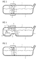
- Figure 1 shows a plastic fuel tank 1 in a cross section.
- the fuel tank 1 is filled with fuel 2.
- a signal source for a radar signal, a transmitting and receiving unit and an evaluation circuit is arranged as a unit 4.
- a trained as a waveguide 5 waveguide is arranged such that a radiated from the transmitting and receiving unit radar signal 6 is radiated through the bottom 3 in the fuel tank 1 and vertically guided by the waveguide 5.
- the waveguide 5 has at the lower end 7 and at the upper end 8 openings through which the interior of the waveguide 5 is in communication with the interior of the fuel tank 1, so that the fuel levels in the fuel tank 1 and in the waveguide 5 are equal.
- a floating float 9 is arranged, which improves the reflection of the irradiated radar signal 6.
- the radar signal 10 reflected by the underside of the float 9 is fed via the transmitting and receiving unit in the structural unit 4 to the evaluation unit, in which an electrical signal for the filling level is formed from the transit time of the radar signal 6, 10.
- the fuel tank 1 shown in Figure 2 differs from the fuel tank of Figure 1 in that the waveguide consists of two parallel wires 11 and a bridge connecting the two wires 11 12, wherein the bridge 12 is formed as a float. Furthermore, the assembly 4, which is the signal source, the transmitting and receiving unit and the evaluation circuit includes disposed above the fuel tank 1. The radar signal 6 is in turn radiated through the wall of the fuel tank 1 in one of the functioning as a waveguide wires 11, transferred from the bridge 12 in the other wire 11 and guided over him again in the direction of the transmitting and receiving unit.
- the fuel tank 1 in FIG. 3 has two structural units 4 consisting of signal source, transmitting and receiving unit and evaluation unit, which are arranged above and below the fuel tank 1.
- the radar signals 6, 6 'irradiated by the two structural units 4 are reflected at the bottom and top of the float 9 and returned to the respective structural units 4 via the waveguide 5.
- the fill level can be determined particularly accurately, since level-related changes in the distance between the upper wall and the bottom 3 can be calculated out by the evaluation unit.
- FIG 4 designed as a saddle tank fuel tank 1 is shown, the two chambers 13, 14 are separated from each other in the lower region of the fuel tank 1 by the saddle 15.
- a conveyor unit 16 for conveying fuel from the fuel tank 1 via a feed line 17 to an internal combustion engine, not shown, is arranged.
- the delivery unit 16 has a flange 18 which closes an opening in the fuel tank 1. The opening is used to mount the conveyor unit 16.
- a waveguide 5 is attached on the flange 18, a waveguide 5 is attached. Lack of space in the chamber 13, the waveguide 5 has a curved course, so that it extends over the saddle 15 into the bottom region of the chamber 14.
- the non-linear design of the waveguide 5 allows, despite the lack of space, the connection of the waveguide 5 to the flange 18 of the conveyor unit 16, so that no separate opening for the assembly of the waveguide 5 must be provided.
- the waveguide 5 differs from the embodiment according to FIG. 1 in that, in addition to the signal line in the waveguide 5, a wire 18 is arranged coaxially.
Landscapes
- Physics & Mathematics (AREA)
- Electromagnetism (AREA)
- Thermal Sciences (AREA)
- Fluid Mechanics (AREA)
- General Physics & Mathematics (AREA)
- Cooling, Air Intake And Gas Exhaust, And Fuel Tank Arrangements In Propulsion Units (AREA)
- Details Of Rigid Or Semi-Rigid Containers (AREA)
Applications Claiming Priority (2)
| Application Number | Priority Date | Filing Date | Title |
|---|---|---|---|
| DE102005044003 | 2005-09-14 | ||
| DE102005049278A DE102005049278B4 (de) | 2005-09-14 | 2005-10-14 | Vorrichtung zur Messung von Füllständen mittels geführter Wellen in einem Kraftstoffbehälter |
Publications (2)
| Publication Number | Publication Date |
|---|---|
| EP1764591A2 true EP1764591A2 (fr) | 2007-03-21 |
| EP1764591A3 EP1764591A3 (fr) | 2007-04-11 |
Family
ID=37113684
Family Applications (1)
| Application Number | Title | Priority Date | Filing Date |
|---|---|---|---|
| EP06120433A Withdrawn EP1764591A3 (fr) | 2005-09-14 | 2006-09-11 | Dispositif destiné à la mesure de niveaux de remplissage dans un réservoir d'essence |
Country Status (2)
| Country | Link |
|---|---|
| EP (1) | EP1764591A3 (fr) |
| DE (1) | DE102005049278B4 (fr) |
Cited By (3)
| Publication number | Priority date | Publication date | Assignee | Title |
|---|---|---|---|---|
| EP3165883B1 (fr) * | 2015-11-05 | 2018-08-08 | VEGA Grieshaber KG | Capteur radar de niveau de remplissage dote de blindage |
| US20200041324A1 (en) * | 2018-08-02 | 2020-02-06 | Vega Grieshaber Kg | Radar sensor for fill level or point level measurement |
| WO2024235605A1 (fr) * | 2023-05-12 | 2024-11-21 | Krohne Messtechnik Gmbh | Dispositif de mesure de niveau basé sur un radar pour détecter le niveau d'un milieu à faible permittivité se situant dans un récipient |
Families Citing this family (7)
| Publication number | Priority date | Publication date | Assignee | Title |
|---|---|---|---|---|
| DE102008017070A1 (de) * | 2008-04-03 | 2009-10-22 | Continental Automotive Gmbh | Vorrichtung zum Bestimmen einer Füllstandshöhe einer Flüssigkeit in einem Behälter |
| DE102010040314A1 (de) | 2010-09-07 | 2012-03-08 | Robert Bosch Gmbh | Vorrichtung und Verfahren zur Bestimmung eines Füllstandes eines Mediums in einem Vorratsbehälter |
| DE102010040315A1 (de) | 2010-09-07 | 2012-03-08 | Robert Bosch Gmbh | Vorrichtung zur Bestimmung eines Füllstands in einem Vorratsbehälter |
| DE102010040312A1 (de) | 2010-09-07 | 2012-03-08 | Robert Bosch Gmbh | Vorrichtung zur Bestimmung eines Füllstandes eines Mediums in einem Vorratsbehälter |
| DE102013101872A1 (de) * | 2013-02-26 | 2014-08-28 | boden & grundwasser GmbH Dr. Rainer Klein | Messverfahren |
| DE102013207604B4 (de) * | 2013-04-25 | 2023-04-06 | Krohne S.A. | Füllstandmessgerät |
| DE102013226778A1 (de) * | 2013-12-19 | 2015-06-25 | Vega Grieshaber Kg | Radarfüllstandsmessgerät |
Citations (1)
| Publication number | Priority date | Publication date | Assignee | Title |
|---|---|---|---|---|
| WO2001063219A2 (fr) * | 2000-02-23 | 2001-08-30 | Cambridge Consultants Limited | Reflectometrie temporelle |
Family Cites Families (10)
| Publication number | Priority date | Publication date | Assignee | Title |
|---|---|---|---|---|
| US4729245A (en) * | 1986-01-02 | 1988-03-08 | Massachusetts Institute Of Technology | Method and apparatus for monitoring liquid volume/mass in tanks |
| US4786857A (en) * | 1986-04-24 | 1988-11-22 | Charles L. Mohr | Methods and apparatus for time domain reflectometry determination of relative proportion, fluid inventory and turbulence |
| DE4419462C2 (de) * | 1994-06-05 | 1999-12-09 | Krohne Messtechnik Kg | Berührungsloser Füllstandsmesser |
| US5910188A (en) * | 1996-04-30 | 1999-06-08 | Triumph Controls, Inc. | Flexible probe with separation adjustment |
| DE19820839A1 (de) * | 1998-05-04 | 1999-11-11 | Fafnir Gmbh | Füllstand-Meßvorrichtung |
| US6300897B1 (en) * | 1999-07-02 | 2001-10-09 | Rosemount Inc. | Stabilization in a radar level gauge |
| DE19958584C1 (de) * | 1999-11-08 | 2001-02-01 | Krohne Sa | Füllstandmessgerät |
| DE10003226A1 (de) * | 2000-01-26 | 2001-08-02 | Volkswagen Ag | Füllstandsmeßeinrichtung |
| DE10027150A1 (de) * | 2000-05-31 | 2001-12-06 | Volkswagen Ag | Einrichtung und Verfahren zur Erfassung eines Füllstandes |
| DE10344259A1 (de) * | 2003-09-23 | 2005-05-12 | Endress & Hauser Gmbh & Co Kg | Anordnung zur Füllstandmessung in einem mit einem Peilrohr ausgestatteten Tank |
-
2005
- 2005-10-14 DE DE102005049278A patent/DE102005049278B4/de not_active Expired - Fee Related
-
2006
- 2006-09-11 EP EP06120433A patent/EP1764591A3/fr not_active Withdrawn
Patent Citations (1)
| Publication number | Priority date | Publication date | Assignee | Title |
|---|---|---|---|---|
| WO2001063219A2 (fr) * | 2000-02-23 | 2001-08-30 | Cambridge Consultants Limited | Reflectometrie temporelle |
Cited By (4)
| Publication number | Priority date | Publication date | Assignee | Title |
|---|---|---|---|---|
| EP3165883B1 (fr) * | 2015-11-05 | 2018-08-08 | VEGA Grieshaber KG | Capteur radar de niveau de remplissage dote de blindage |
| US20200041324A1 (en) * | 2018-08-02 | 2020-02-06 | Vega Grieshaber Kg | Radar sensor for fill level or point level measurement |
| US11860023B2 (en) * | 2018-08-02 | 2024-01-02 | Vega Grieshaber Kg | Radar sensor for fill level or point level measurement |
| WO2024235605A1 (fr) * | 2023-05-12 | 2024-11-21 | Krohne Messtechnik Gmbh | Dispositif de mesure de niveau basé sur un radar pour détecter le niveau d'un milieu à faible permittivité se situant dans un récipient |
Also Published As
| Publication number | Publication date |
|---|---|
| EP1764591A3 (fr) | 2007-04-11 |
| DE102005049278B4 (de) | 2007-08-16 |
| DE102005049278A1 (de) | 2007-03-15 |
Similar Documents
| Publication | Publication Date | Title |
|---|---|---|
| DE2839634C2 (de) | Flüssigkeitsstand-Meßgerät | |
| EP2059773B1 (fr) | Unité de transport de carburant comprenant un indicateur de niveau fonctionnant par ultrasons | |
| EP1305581A1 (fr) | Dispositif de mesure du niveau d'un materiau de remplissage dans un contenant | |
| DE4328046A1 (de) | Ultraschall-Flüssigkeitsstandsensor | |
| EP1081470B1 (fr) | Dispositif de mesure de niveau de liquide dans un réservoir | |
| DE102012205640B4 (de) | Füllstandsgeber | |
| DE102005049278B4 (de) | Vorrichtung zur Messung von Füllständen mittels geführter Wellen in einem Kraftstoffbehälter | |
| DE10312100A1 (de) | Vorrichtung zur Messung eines Füllstandes einer Flüssigkeit in einem Behälter | |
| EP2848902B1 (fr) | Procédé de détermination d'un niveau de remplissage d'un milieu et dispositif de détermination d'un niveau de remplissage d'un milieu | |
| DE19901814B4 (de) | Niveauschalter | |
| EP1325351A1 (fr) | Dispositif destine a determiner le niveau de remplissage d'un materiau dans un contenant | |
| DE10360107B3 (de) | Ultraschall-Peilstab | |
| DE102012002011A1 (de) | Vorrichtung zur Messung eines Füllstands einer Flüssigkeit und ölgeschmierter Motor | |
| DE202016102013U1 (de) | Bestimmen eines Füllstands eines Mediums | |
| EP0175904A1 (fr) | Dispositif pour mesurer le niveau de remplissage des liquides | |
| EP1274973A2 (fr) | Dispositif de determination du niveau de remplissage d'un recipient avec un agent de remplissage | |
| DE10312101A1 (de) | Vorrichtung zur Messung eines Füllstandes einer Flüssigkeit in einem Behälter | |
| DE10043838A1 (de) | Füllstandsmeßvorrichtung | |
| DE202008007989U1 (de) | Abstandshalteelement zur Zentrierung eines inneren Leiters | |
| WO2001096900A1 (fr) | Procede et dispositif d'amelioration de la stabilite a la temperature et de la resistance au vieillissement de mesureurs de niveau a radar a l'aide d'une reference mecanique | |
| DE102010040315A1 (de) | Vorrichtung zur Bestimmung eines Füllstands in einem Vorratsbehälter | |
| DE10130540A1 (de) | Füllstandsmessgerät zum Ermitteln des Flüssigkeitspegels in einem Behälter | |
| DE8713874U1 (de) | Abstandsmeßeinrichtung für eine Baumaschine | |
| DE102006032346A1 (de) | Vorrichtung zur Messung von Füllständen in einem Kraftstoffbehälter | |
| DE102016107049B3 (de) | Bestimmen eines Füllstands eines Mediums |
Legal Events
| Date | Code | Title | Description |
|---|---|---|---|
| PUAI | Public reference made under article 153(3) epc to a published international application that has entered the european phase |
Free format text: ORIGINAL CODE: 0009012 |
|
| PUAL | Search report despatched |
Free format text: ORIGINAL CODE: 0009013 |
|
| AK | Designated contracting states |
Kind code of ref document: A2 Designated state(s): AT BE BG CH CY CZ DE DK EE ES FI FR GB GR HU IE IS IT LI LT LU LV MC NL PL PT RO SE SI SK TR |
|
| AX | Request for extension of the european patent |
Extension state: AL BA HR MK YU |
|
| AK | Designated contracting states |
Kind code of ref document: A3 Designated state(s): AT BE BG CH CY CZ DE DK EE ES FI FR GB GR HU IE IS IT LI LT LU LV MC NL PL PT RO SE SI SK TR |
|
| AX | Request for extension of the european patent |
Extension state: AL BA HR MK YU |
|
| 17P | Request for examination filed |
Effective date: 20071011 |
|
| 17Q | First examination report despatched |
Effective date: 20071105 |
|
| AKX | Designation fees paid |
Designated state(s): DE ES FR GB IT |
|
| RAP1 | Party data changed (applicant data changed or rights of an application transferred) |
Owner name: CONTINENTAL AUTOMOTIVE GMBH |
|
| STAA | Information on the status of an ep patent application or granted ep patent |
Free format text: STATUS: THE APPLICATION IS DEEMED TO BE WITHDRAWN |
|
| 18D | Application deemed to be withdrawn |
Effective date: 20171011 |